
Implementing Many-Lights Rendering with IES-Based Lights


Abstract
1. Introduction
- is the surface normal;
- is the hemisphere centered around ;
- and are the directions of incoming and reflected light, respectively;
- and are the incoming and the reflected radiances, respectively;
- is the Bidirectional Reflectance Distribution Function (BRDF), which describes the amount of radiance reflected in the direction given the radiance coming from direction .
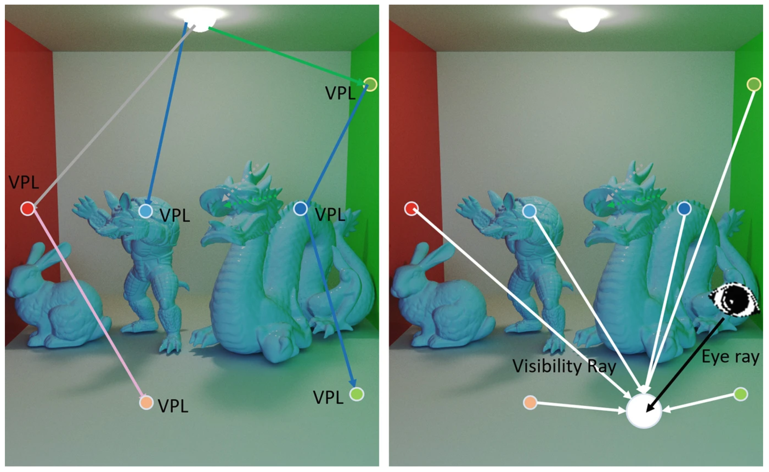
2. State of the Art on Many-Lights Rendering Techniques
- M is the number of generated VPLs
- is the position of the k-th VPL
- is the visibility term between the k-th VPL and the point we are shading
- is the BRDFs of point . We use a simplified notation because only diffuse reflection is considered.
- is the geometry term between the k-th VPL and the point we are shading
- is the “flux” of the k-th VPL (i.e., the component of radiance “emitted” by the k-th VPL). It is calculated as: .
Reflective Shadow Maps
- a depth value, , as in a standard shadow map;
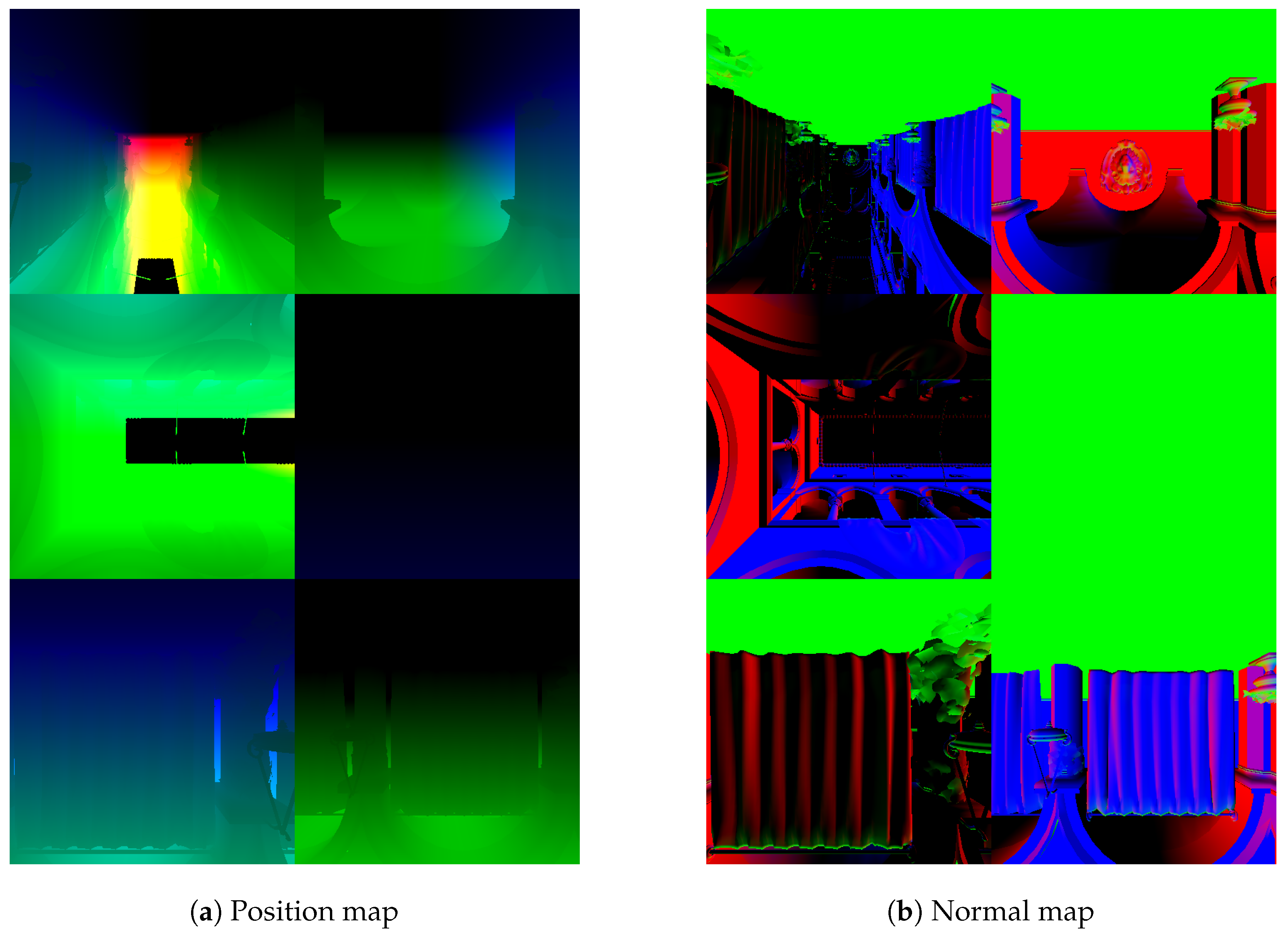
- the world space position of the pixel ;
- the normal in world space ;
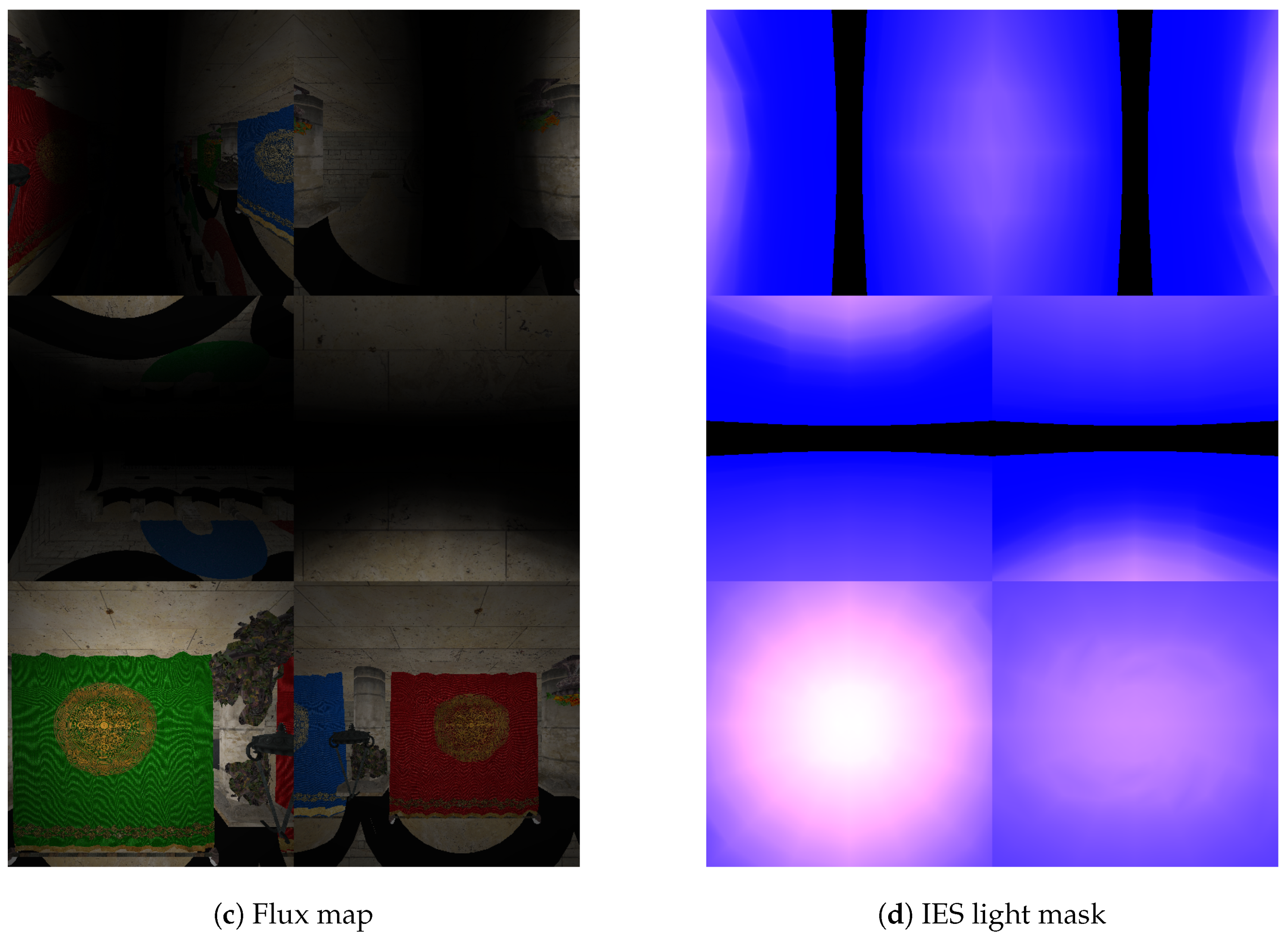
- the reflected radiant flux , which corresponds to the amount of luminous power leaving a surface.
3. Photometric Description of Light Sources
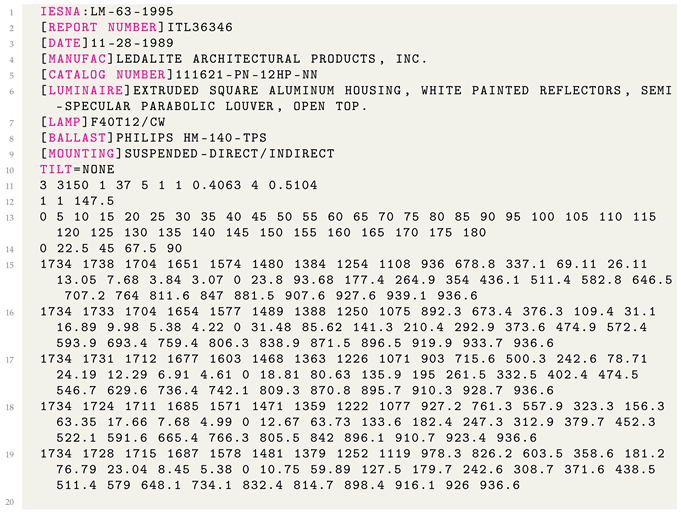
- Information about the luminaire product (line 1 to line 10): a list of metadata, providing information about the specific luminaire (e.g., model number, manufacturer, destination of use, model of the lamp(s) and ballast, type of mounting, etc.). The list of keywords is not fixed in type, order, or number of elements. Thus, IES files may differ in this section; however, it is not used during the rendering process.
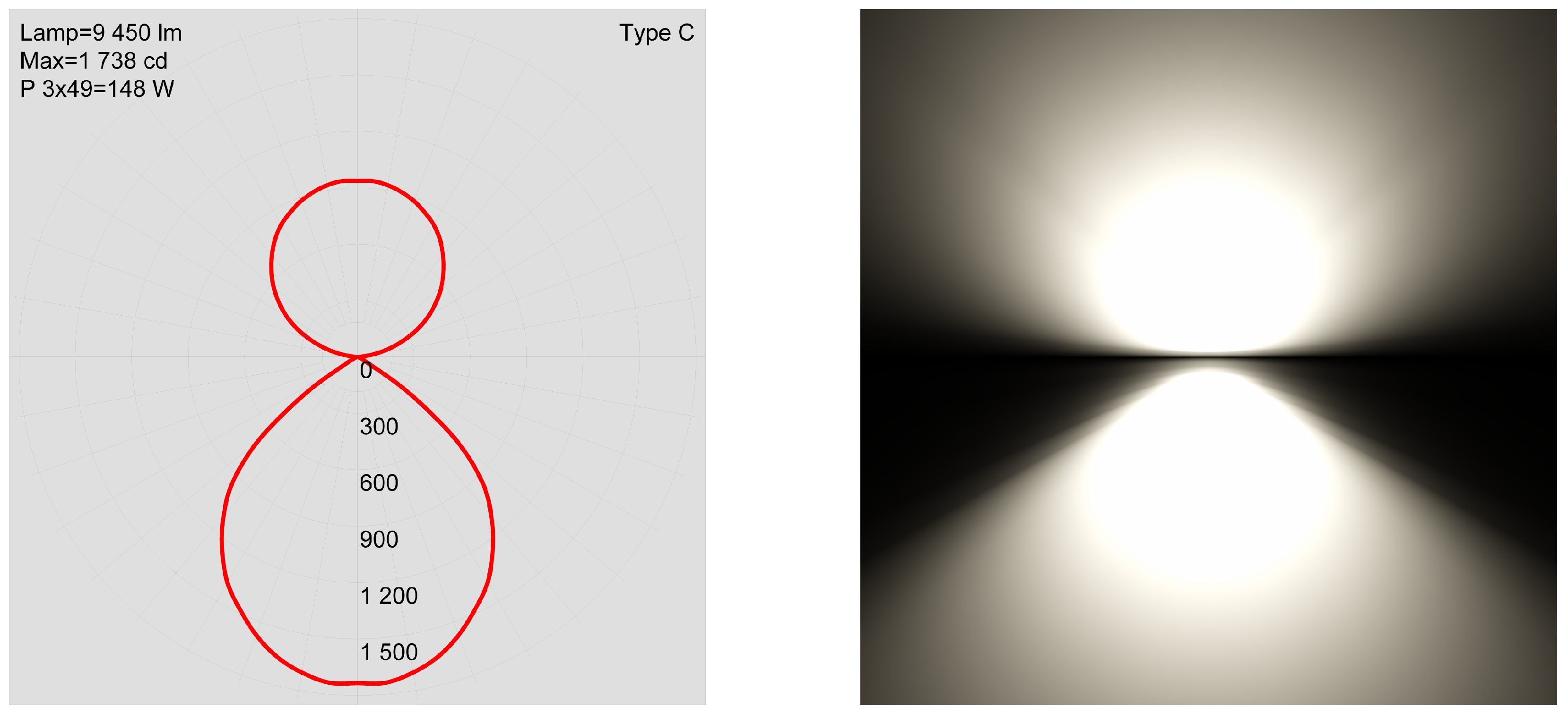
- Information about the measurement test (lines 11 and 12): a list of values related to the measurement test on the actual luminaire. The values in line 11 represent the number of lamps inside the luminaire, the luminous flux of each lamp, a multiplication factor of light intensity, the number of vertical and horizontal angles considered in the measurements, the Photometric Type of the luminaire, the unit of measurement (1 for feet, 2 for meters), and, finally, length, width, and height of the emitting surface of the luminaire. The values in line 12 provide information on the electrical ballast and the input power of the luminaire.
- Measured photometric data (line 13 to line 19): the actual measured data, which consist of the core part of an IES file and the data actually used in the rendering process. The luminaire’s photometric data are captured by locating them at the center of an imaginary sphere and measuring light intensity values at some points on the surface of this sphere. These points are expressed using polar coordinates relative to a grid called photometric web. The measured samples define a volume that is called photometric solid. Lines 13 and 14 show the lists of the vertical and horizontal angles on the photometric web representing the measured samples. The numbers of the considered angles are stated in line 11 (in our example, thirty-seven vertical angles and five horizontal angles). Lines 15 to 19 show the list of luminous intensity values (expressed in candelas) captured at each angle pair (a line for each horizontal angle, each consisting of 37 values).
| Listing 1. The content of an IES file. |
 |
4. Method
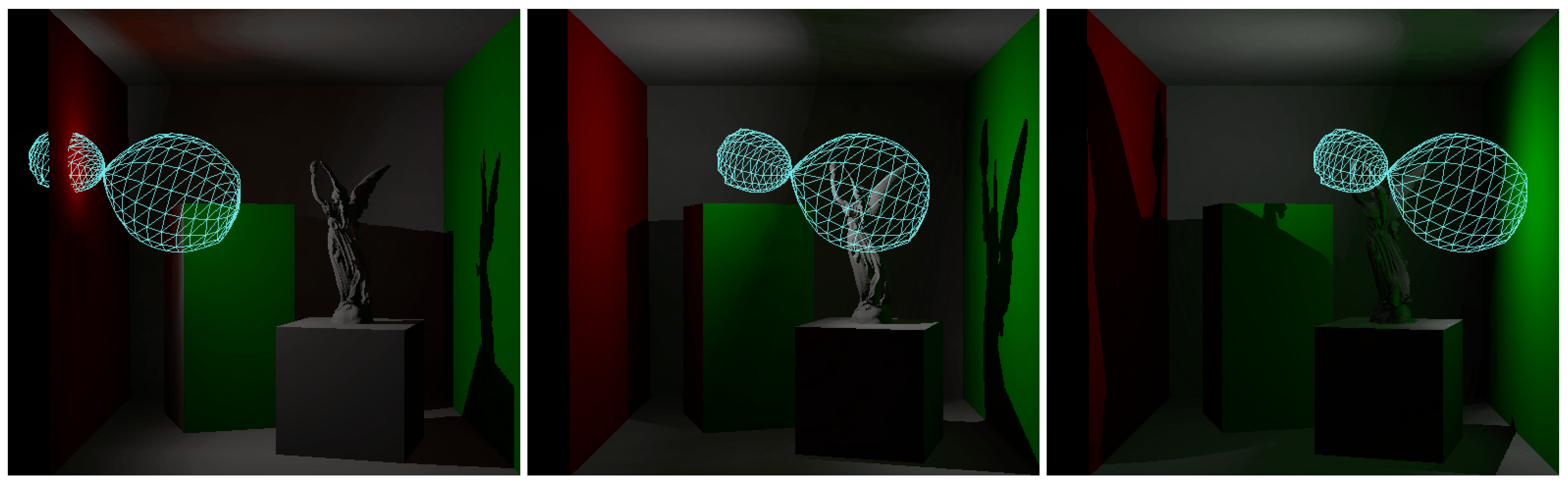
- we implemented a parser for the IES file format, which creates a polygon mesh representing the photometric solid of a luminaire. This mesh is then used in the rendering process to influence the direct and indirect illumination components;
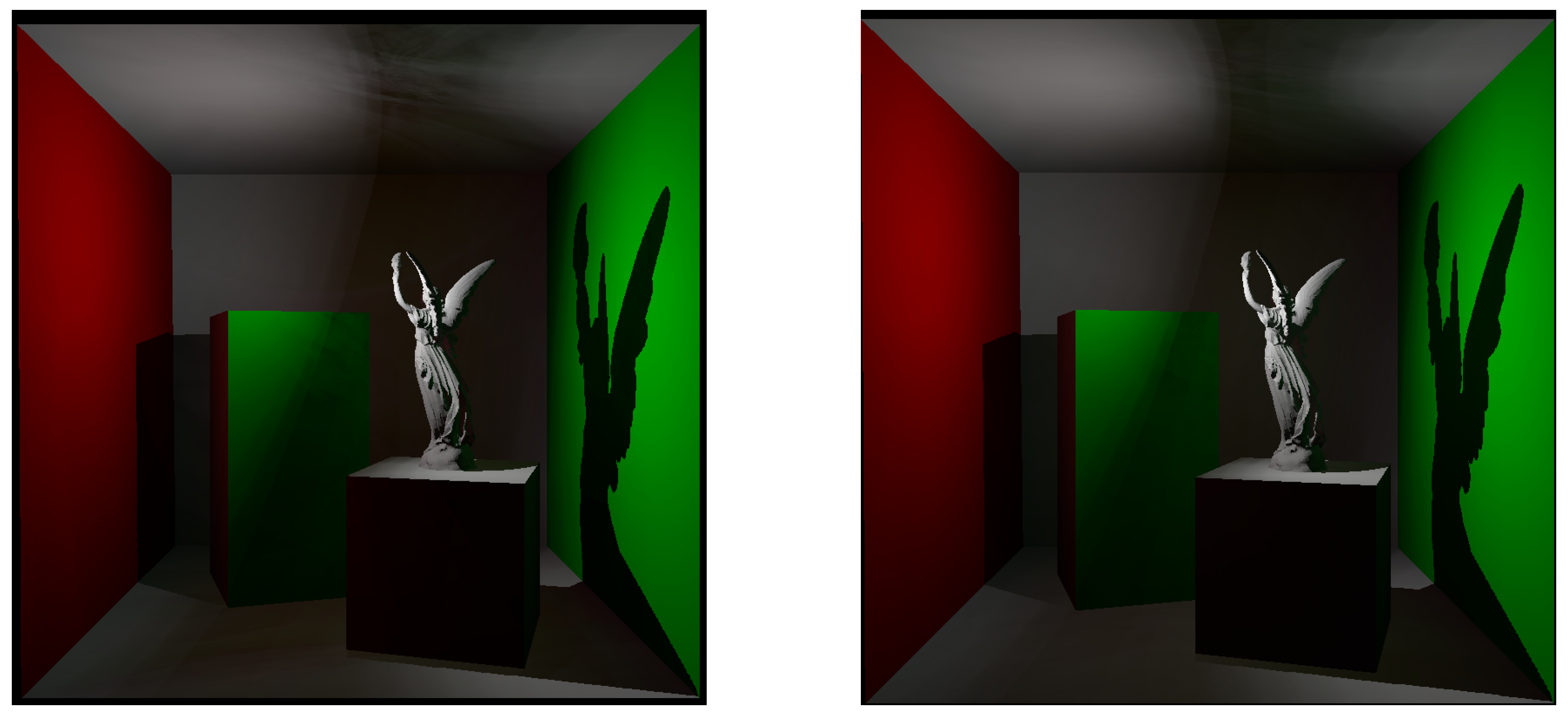
- we weighted the emission from the VPLs on the basis of the parsed data from the IES files. This affects not only the direct illumination component (leading to a more realistic rendering of the area and surfaces closer to the light source) but also the indirect illumination component because the placement of the VPLs is tuned by the actual volume of emission, which is no longer perfectly spherical but described by the data from a real luminaire (Figure 2).
4.1. Implementation Details
- the Crytek Sponza, which consists of 262,267 triangles. The scene considers only diffuse surfaces and also presents several textures. The original file (downloaded from [35]) was resized by the authors before use.
4.2. Applying an IES Light in a Virtual Scene
4.3. Enhancing Reflective Shadow Maps with IES Data
| Listing 2. IES light mask generation: false colors computation in fragment shader. |
 |
- Red color channel: we store the length of the vector that goes from the position of the light to the processed fragment, i.e., the luminous intensity emitted from the light source in that direction.
- Green color channel: distance_to_furthest_ies_vertex is the original maximum distance between the origin and a vertex of the photometric solid. Dividing the distance of the fragment from the light by this value, we compute an intensity modifier based on the maximum intensity that the light source can emit in candelas. This will compensate scaling transformations applied to the original photometric solid once transformed to be used in the scene. The resulting value is always contained in the range .
- Blue color channel: since a fragment was generated, the solid emits light in that direction, so the variable emitting_along_direction_l is set to . Because the G-buffer is initialized with , the final cube map will have non-zero values only for fragments corresponding to actual direction of emission from the light source.
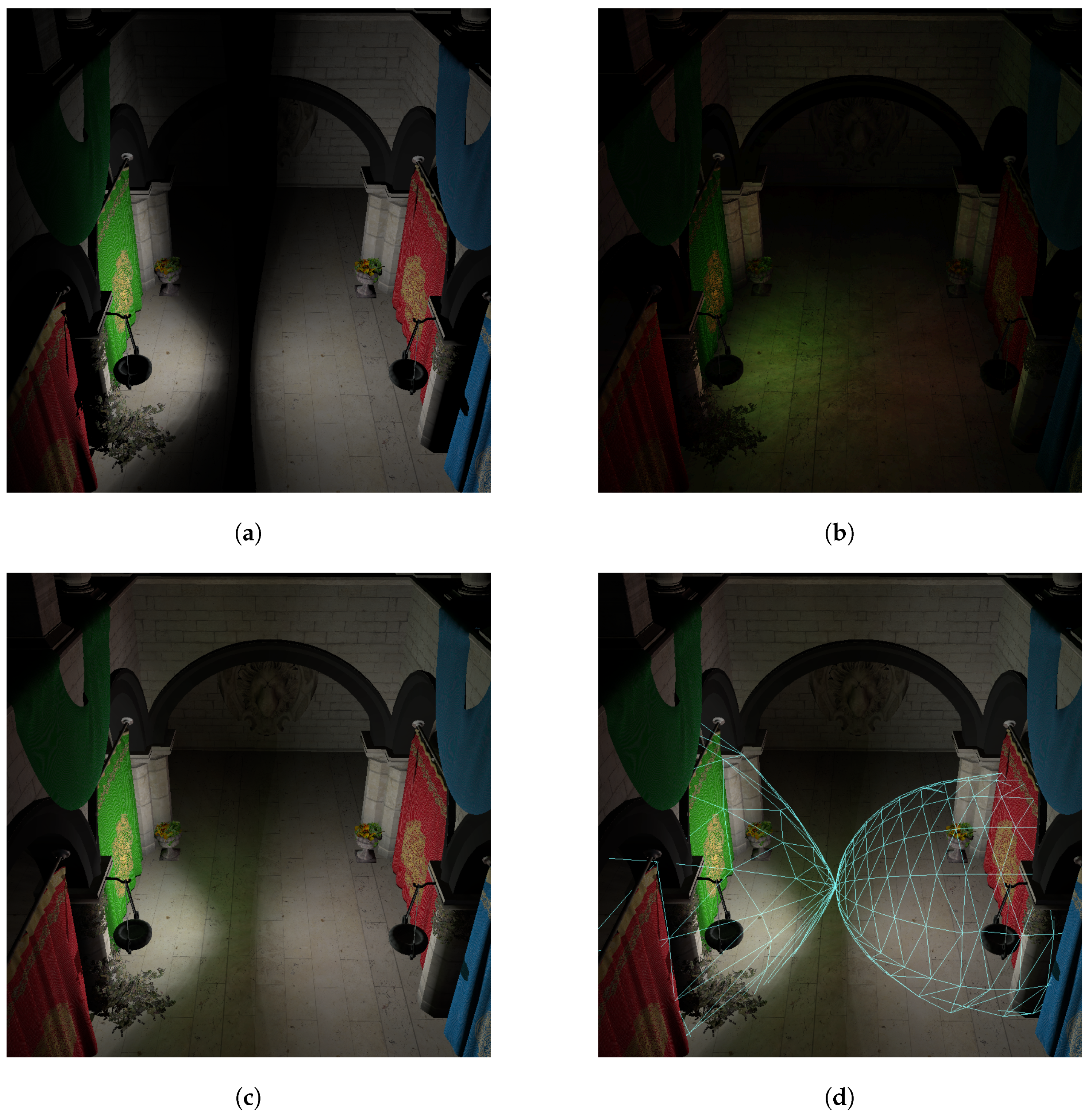
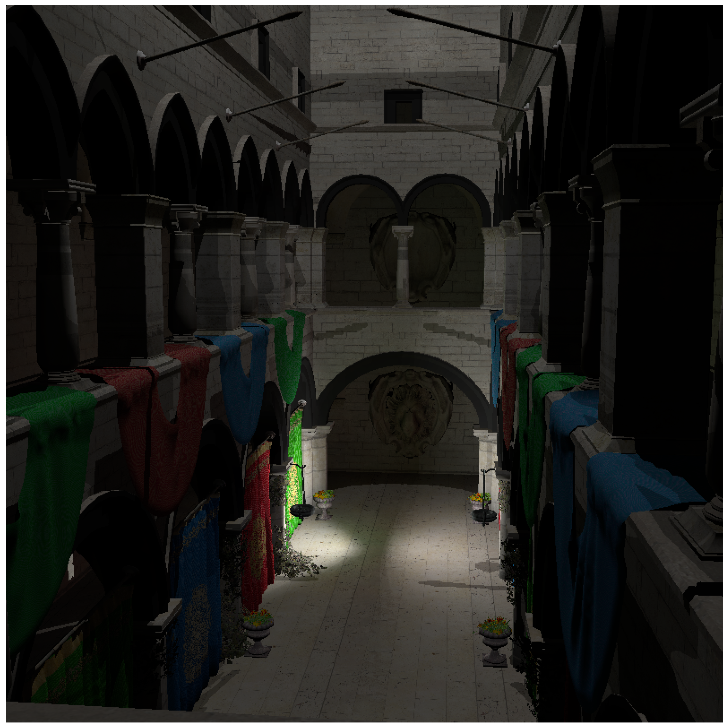
- direct illumination component: for each light source present in the scene, the G-buffer storing the standard shadow map is checked to see if the considered fragment is illuminated. If not in shadow, the direct illumination component is computed following the standard screenspace approach of deferred rendering, but the resulting value is weighted by the values sampled in the IES light mask. The blue channel, corresponding to a boolean flag, tells the shader whether the light source emits light in that direction. If it does not, the contribution of that light is set to zero. On the other hand, if the contribution exists, the value in the red channel (possibly corrected by the component in the green channel) can be used as a multiplier for the intensity. An example of the rendering produced considering only this component is a scene that can be seen in Figure 4a.
- indirect illlumination component: the computation is based on the application of Equation (3) as discussed in Section 2 but computed using G-buffers consisting of cube maps, and weighting the final result using the values sampled in the IES light mask to take into account the light intensity actually emitted in a direction. Figure 4b shows a preview of the indirect illumination component created using our enhanced RSM technique. A multiplication factor of 4 is used for a better visualization.
5. Results and Discussion
6. Conclusions and Future Work
Author Contributions
Funding
Institutional Review Board Statement
Informed Consent Statement
Data Availability Statement
Conflicts of Interest
References
- Kajiya, J.T. The Rendering Equation. In Proceedings of the SIGGRAPH ’86: 13th Annual Conference on Computer Graphics and Interactive Techniques, Dallas, TX, USA, 18–22 August 1986; Association for Computing Machinery: New York, NY, USA, 1986; pp. 143–150. [Google Scholar] [CrossRef]
- Pharr, M.; Jakob, W.; Humphreys, G. Physically Based Rendering: From Theory to Implementation, 4th ed.; The MIT Press: Cambridge, MA, USA, 2023. [Google Scholar]
- Akenine-Möller, T.; Haines, E.; Hoffman, N.; Pesce, A.; Iwanicki, M.; Hillaire, S. Real-Time Rendering, 4th ed.; AK Peters/CRC Press: Boca Raton, FL, USA, 2018; p. 1200. [Google Scholar]
- Haines, E.; Akenine-Möller, T. (Eds.) Ray Tracing Gems; Apress: New York, NY, USA, 2019. [Google Scholar]
- Marrs, A.; Shirley, P.; Wald, I. (Eds.) Ray Tracing Gems II; Apress: New York, NY, USA, 2021. [Google Scholar]
- Wang, T. High-Performance Many-Light Rendering. In Encyclopedia of Computer Graphics and Games; Springer International Publishing: Cham, Switzerland, 2020; pp. 1–6. [Google Scholar] [CrossRef]
- Dachsbacher, C.; Křivánek, J.; Hašan, M.; Arbree, A.; Walter, B.; Novák, J. Scalable Realistic Rendering with Many-Light Methods. Comput. Graph. Forum 2014, 33, 88–104. [Google Scholar] [CrossRef]
- Dachsbacher, C.; Stamminger, M. Reflective Shadow Maps. In Proceedings of the I3D ’05: 2005 Symposium on Interactive 3D Graphics and Games, Washington, DC, USA, 3–6 April 2005; Association for Computing Machinery: New York, NY, USA, 2005; pp. 203–231. [Google Scholar] [CrossRef]
- Jensen, H.W. Realistic Image Synthesis Using Photon Mapping; A. K. Peters Ltd.: Wellesley, MA, USA, 2001. [Google Scholar]
- Keller, A. Instant Radiosity. In Proceedings of the SIGGRAPH ’97: 24th Annual Conference on Computer Graphics and Interactive Techniques, Los Angeles, CA, USA, 3–8 August 1997; pp. 49–56. [Google Scholar] [CrossRef]
- Hašan, M.; Křivánek, J.; Walter, B.; Bala, K. Virtual Spherical Lights for Many-Light Rendering of Glossy Scenes. In SIGGRAPH Asia ’09: ACM SIGGRAPH Asia 2009 Papers; Association for Computing Machinery: New York, NY, USA, 2009. [Google Scholar] [CrossRef]
- Hedman, P.; Karras, T.; Lehtinen, J. Sequential Monte Carlo Instant Radiosity. In Proceedings of the I3D ’16: 20th ACM SIGGRAPH Symposium on Interactive 3D Graphics and Games, Redmond, WA, USA, 26–28 February 2016; Association for Computing Machinery: New York, NY, USA, 2016; pp. 121–128. [Google Scholar] [CrossRef]
- Yuksel, C. Stochastic Lightcuts for Sampling Many Lights. IEEE Trans. Vis. Comput. Graph. 2021, 27, 4049–4059. [Google Scholar] [CrossRef] [PubMed]
- Tabellion, E.; Lamorlette, A. An Approximate Global Illumination System for Computer Generated Films. ACM Trans. Graph. 2004, 23, 469–476. [Google Scholar] [CrossRef]
- Ritschel, T.; Eisemann, E.; Ha, I.; Kim, J.D.K.; Seidel, H.P. Making Imperfect Shadow Maps View-Adaptive: High-Quality Global Illumination in Large Dynamic Scenes. Comput. Graph. Forum 2011, 30, 2258–2269. [Google Scholar] [CrossRef]
- Walter, B.; Fernandez, S.; Arbree, A.; Bala, K.; Donikian, M.; Greenberg, D.P. Lightcuts: A Scalable Approach to Illumination. ACM Trans. Graph. 2005, 24, 1098–1107. [Google Scholar] [CrossRef]
- Shi, X.; Wang, L.; Wu, J.; Fan, R.; Hao, A. Foveated Stochastic Lightcuts. IEEE Trans. Vis. Comput. Graph. 2022, 28, 3684–3693. [Google Scholar] [CrossRef] [PubMed]
- Hašan, M.; Pellacini, F.; Bala, K. Matrix Row-Column Sampling for the Many-Light Problem. ACM Trans. Graph. 2007, 26, 26-es. [Google Scholar] [CrossRef]
- Saito, T.; Takahashi, T. Comprehensible Rendering of 3-D Shapes. In Proceedings of the SIGGRAPH ’90: 17th Annual Conference on Computer Graphics and Interactive Techniques, Dallas, TX, USA, 6–10 August 1990; Association for Computing Machinery: New York, NY, USA, 1990; pp. 197–206. [Google Scholar] [CrossRef]
- Keller, A.; Heidrich, W. Interleaved Sampling. In Eurographics Workshop on Rendering; Gortle, S.J., Myszkowski, K., Eds.; The Eurographics Association: Limassol, Cyprus, 2001. [Google Scholar] [CrossRef]
- Segovia, B.; Iehl, J.C.; Mitanchey, R.; Péroche, B. Non-Interleaved Deferred Shading of Interleaved Sample Patterns. In Proceedings of the GH ’06: 21st ACM SIGGRAPH/EUROGRAPHICS Symposium on Graphics Hardware, Vienna, Austria, 3–4 September 2006; Association for Computing Machinery: New York, NY, USA, 2006; pp. 53–60. [Google Scholar] [CrossRef]
- Segovia, B.; Wald, I. Screen Space Spherical Harmonics Filters for Instant Global Illumination; Technical Report; Intel Corporation Research: Santa Clara, CA, USA, 2010. [Google Scholar]
- Nichols, G.; Wyman, C. Multiresolution Splatting for Indirect Illumination. In Proceedings of the I3D ’09: 2009 Symposium on Interactive 3D Graphics and Games, Boston, MA, USA, 27 February–1 March 2009; Association for Computing Machinery: New York, NY, USA, 2009; pp. 83–90. [Google Scholar] [CrossRef]
- Olsson, O.; Assarsson, U. Tiled Shading. J. Graph. GPU Game Tools 2011, 15, 235–251. [Google Scholar] [CrossRef]
- Nabata, K.; Iwasaki, K. Adaptive Irradiance Sampling for Many-Light Rendering of Subsurface Scattering. IEEE Trans. Vis. Comput. Graph. 2022, 28, 3324–3335. [Google Scholar] [CrossRef] [PubMed]
- Noh, G.; Choi, H.; Moon, B. Enhanced Direct Lighting Using Visibility-Aware Light Sampling. In Advances in Computer Graphics; Sheng, B., Bi, L., Kim, J., Magnenat-Thalmann, N., Thalmann, D., Eds.; Springer: Cham, Switzerland, 2024; pp. 187–198. [Google Scholar]
- Ritschel, T.; Grosch, T.; Kim, M.H.; Seidel, H.P.; Dachsbacher, C.; Kautz, J. Imperfect shadow maps for efficient computation of indirect illumination. ACM Trans. Graph. 2008, 27, 129. [Google Scholar] [CrossRef]
- Debevec, P. Image-Based Lighting. In Proceedings of the SIGGRAPH ’06: ACM SIGGRAPH 2006 Courses, Boston, MA, USA, 30 July–3 August 2006; Association for Computing Machinery: New York, NY, USA, 2006; p. 4-es. [Google Scholar] [CrossRef]
- IES File Format. Available online: https://blog.ansi.org/2020/02/standard-file-photometric-data-ies-lm-63-19/ (accessed on 20 December 2023).
- Illuminating Engineering Society Homepage. Available online: https://www.ies.org/ (accessed on 20 December 2023).
- Lagarde, S.; Langlands, A. Moving Frostbite to PBR. In Physically Based Shading in Theory and Practice; ACM SIGGRAPH 2014 Courses; Association for Computing Machinery: New York, NY, USA, 2014. [Google Scholar]
- Lagarde, S. Moving Frostbite to Physically Based Rendering 3.0. Available online: https://seblagarde.files.wordpress.com/2015/07/course_notes_moving_frostbite_to_pbr_v32.pdf (accessed on 20 December 2023).
- Unreal Engine Documentation: IES Light Profiles. Available online: https://docs.unrealengine.com/5.0/en-US/using-ies-light-profiles-in-unreal-engine/ (accessed on 20 December 2023).
- IESviewer Homepage. Available online: http://photometricviewer.com/ (accessed on 20 December 2023).
- McGuire, M. Computer Graphics Archive. Available online: https://casual-effects.com/data (accessed on 20 December 2023).
- Jacobson, A. Common 3D Test Models Repository. Available online: https://github.com/alecjacobson/common-3d-test-models (accessed on 20 December 2023).
- Botsch, M.; Kobbelt, L.; Pauly, M.; Alliez, P.; Levy, B. Polygon Mesh Processing; CRC Press: Boca Raton, FL, USA, 2010. [Google Scholar]
- Kessenich, J.; Sellers, G.; Shreiner, D. OpenGL Programming Guide: The Official Guide to Learning OpenGL, Version 4.5 with SPIR-V, 9th ed.; Addison-Wesley Professional: Boston, MA, USA, 2016. [Google Scholar]
- NVIDIA Nsight Graphics. Available online: https://developer.nvidia.com/nsight-graphics (accessed on 20 December 2023).
- Dachsbacher, C.; Stamminger, M. Splatting Indirect Illumination. In Proceedings of the I3D ’06: 2006 Symposium on Interactive 3D Graphics and Games, Redwood City, CA, USA, 14–17 March 2006; Association for Computing Machinery: New York, NY, USA, 2006; pp. 93–100. [Google Scholar] [CrossRef]


| Number of Samples | Min FPS | Max FPS | Average FPS |
|---|---|---|---|
| 400 | 40 | 55 | 49 |
| 100 | 140 | 200 | 170 |
| Number of Samples | Min FPS | Max FPS | Average FPS |
|---|---|---|---|
| 400 | 42 | 52 | 47 |
| 100 | 120 | 184 | 152 |
Disclaimer/Publisher’s Note: The statements, opinions and data contained in all publications are solely those of the individual author(s) and contributor(s) and not of MDPI and/or the editor(s). MDPI and/or the editor(s) disclaim responsibility for any injury to people or property resulting from any ideas, methods, instructions or products referred to in the content. |
© 2024 by the authors. Licensee MDPI, Basel, Switzerland. This article is an open access article distributed under the terms and conditions of the Creative Commons Attribution (CC BY) license (https://creativecommons.org/licenses/by/4.0/).
Share and Cite
Gadia, D.; Lombardo, V.; Maggiorini, D.; Natilla, A. Implementing Many-Lights Rendering with IES-Based Lights. Appl. Sci. 2024, 14, 1022. https://doi.org/10.3390/app14031022
Gadia D, Lombardo V, Maggiorini D, Natilla A. Implementing Many-Lights Rendering with IES-Based Lights. Applied Sciences. 2024; 14(3):1022. https://doi.org/10.3390/app14031022
Chicago/Turabian StyleGadia, Davide, Vincenzo Lombardo, Dario Maggiorini, and Antonio Natilla. 2024. "Implementing Many-Lights Rendering with IES-Based Lights" Applied Sciences 14, no. 3: 1022. https://doi.org/10.3390/app14031022
APA StyleGadia, D., Lombardo, V., Maggiorini, D., & Natilla, A. (2024). Implementing Many-Lights Rendering with IES-Based Lights. Applied Sciences, 14(3), 1022. https://doi.org/10.3390/app14031022