Article

Seismic Response Analysis of Concrete Box-Type Subgrade in High-Speed Railways

1
School of Civil Engineering and Architecture, Beijing Jiaotong University, Beijing 100044, China
2
Beijing Key Laboratory of Rail Transit Engineering, Beijing Jiaotong University, Beijing 100044, China
3
China Railway Design Corporation Limited, Tianjin 300308, China
4
School of Mechanical and Electronic Control Engineering, Beijing Jiaotong University, Beijing 100044, China
5
Department of Mechanical Engineering, KLS Gogte Institute of Technology, Belagavi 590008, India
*
Author to whom correspondence should be addressed.
Appl. Sci. 2024, 14(24), 11899; https://doi.org/10.3390/app142411899
Submission received: 5 November 2024 / Revised: 8 December 2024 / Accepted: 17 December 2024 / Published: 19 December 2024

Abstract

:
China is prone to frequent earthquakes, impacting both the construction and operation of high-speed railways. The seismic response analysis is essential for the promotion and structural optimization of novel box-type subgrade structures. This paper develops a nonlinear integrated spatial dynamic model of a ballastless track and box-type subgrade, investigating structural vibrations under multi-dimensional seismic actions using the time–frequency domain method. A seismic performance analysis of the structure is conducted to examine the influence of seismic intensity on its seismic response. Results indicate that the box-type subgrades exhibit good integrity under seismic actions, primarily undergoing rigid body motion, with forces in all components well below design strength, meeting the Chinese seismic fortification requirements. Compared to traditional simply supported beams, box-type subgrades show better adaptability to earthquakes. As seismic intensity increases, vibrations and deformations of box-type subgrades change linearly, while vibrating forces increase nonlinearly.

1. Introduction

China is located at the junction of the world’s two major seismic belts—the Circum-Pacific Seismic Belt and the Eurasian Seismic Belt. It is squeezed by the Pacific Plate, the Indian Plate, and the Philippine Plate, making it prone to earthquakes with historical records of earthquakes spanning over 3000 years. According to the “China Seismic Hazard Map” [1], more than 50% of China’s land is in regions with an earthquake intensity greater than 7 degrees, resulting in a peak ground acceleration exceeding 0.1 g for most of the national territory. As shown in Figure 1 [2], nearly 10,000 km of China’s “Eight Vertical and Eight Horizontal” high-speed railway network traverse areas with high seismic intensity, posing challenges for both the construction and operational maintenance of high-speed railways in the face of earthquake damage.
The box-type subgrade structure is a novel subgrade structure proposed by Chinese engineers in recent years, which replaces traditional subgrade fillers with concrete structures [3,4]. It has the advantages of small land occupation and high bending, as well as torsional stiffness, offering significant potential for widespread applications [5]. It may also be considered a sustainable option to traditional filler subgrades as it reduces the need for natural aggregates [6]. Earthquakes can be considered random loads with immense destructive power for high-speed railway analysis purposes. If the infrastructure design does not adequately consider the effects of earthquakes, the consequences can be extremely severe. Therefore, it is of great theoretical significance and engineering value to conduct a seismic analysis of the box-type subgrade structure, both for its promotion and structural optimization.
Currently, there have been no reported studies on the vibration response characteristics of high-speed railway box-type subgrades under seismic action. Considering that the box-type subgrade uses concrete structures to completely replace traditional subgrade fillers, and it is structurally similar to traditional simply supported box girders, the present study focuses on the seismic response analysis methods of simply supported box girders to study the box-type subgrade. Scholars at home and abroad have conducted extensive research on the response of bridges under seismic action. Tullini et al. [7,8,9] have specifically studied the structural buckling of box culverts and the interaction between the structure and soil, while also considering the support provided by an elastic half-space, rather than a simple Winkler support. Mylona et al. [10] studied the dynamic response of bridge structures under various combined seismic excitations. Liu et al. [11] discussed the impact of wave propagation effects on the seismic response of railway bridge systems based on the absolute displacement input method (ADM). Toyooka et al. [12] explored the impact of track structures on the seismic response of seismic isolation railway bridge systems. Zhang et al. [13] proposed an integrated bridge-line analysis model based on the longitudinal constraint effect of the ballastless track system. Yang et al. [14] analyzed the influence of track system constraints on the lateral seismic collision effect of simply supported beam bridges. Zhang et al. [15] established a refined spatial model of the CRTS Type-III slab track system on a bridge and conducted research on the dynamic response of the CRTS Type-III slab track system on a bridge under multi-dimensional seismic action. Ai [16] used fiber beam element modeling to analyze the nonlinear elastoplastic seismic response of railway portal piers. Sun Zhifeng [17] conducted a design study on the key structures of large-span steel box portal piers, determining the feasibility of engineering application of portal pier structures.
This paper primarily focuses on the basic requirements for seismic design of box-type subgrades. It establishes a nonlinear ballastless track box-type subgrade integrated spatial dynamic model to study the structure’s seismic response under multi-dimensional seismic action using the time–frequency domain method. Additionally, the study explores the force and deformation characteristics of the box-type subgrade, identifies damage patterns under seismic actions, and examines the impact of different seismic intensities on the structure’s seismic response. These findings provide valuable references for the design and maintenance of box-type subgrades in seismic areas, thereby enhancing the engineering application of this new structural form.

2. Basic Requirements for Seismic Design of Box-Type Subgrades

The seismic design of railway engineering in China mainly relies on the “Seismic Design Code for Railway Engineering” [18]. Referring to the requirements of this specification, the seismic design of high-speed railway box-type subgrades should be designed according to three levels, namely (a) frequent earthquakes, (b) design earthquakes, and (c) rare earthquakes, with the corresponding intensities shown in Table 1. The seismic design of railway box-type subgrades should meet the seismic performance standards specified in Table 2.
Considering the characteristics of the box-type subgrade structure, the seismic defense objectives can refer to those of bridges. The seismic protection objectives and analysis methods for railway bridge structures in China are shown in Table 3. To meet Seismic Performance Requirement I [19]: the structure should remain undamaged or sustain minor damage after an earthquake, ensuring its normal use and maintaining a state of normal serviceability. In accordance with the analysis methods listed in 3, this paper primarily employs the design ground motion level to analyze the seismic response of the box-type subgrade, namely to study the response patterns of the box-type subgrade under ground motion intensities of 0.05 g (Level 6), 0.10 g (Level 7), 0.15 g (Level 7), 0.20 g (Level 8), 0.30 g (Level 8), and 0.40 g (Level 9).

3. Computational Methods and Models

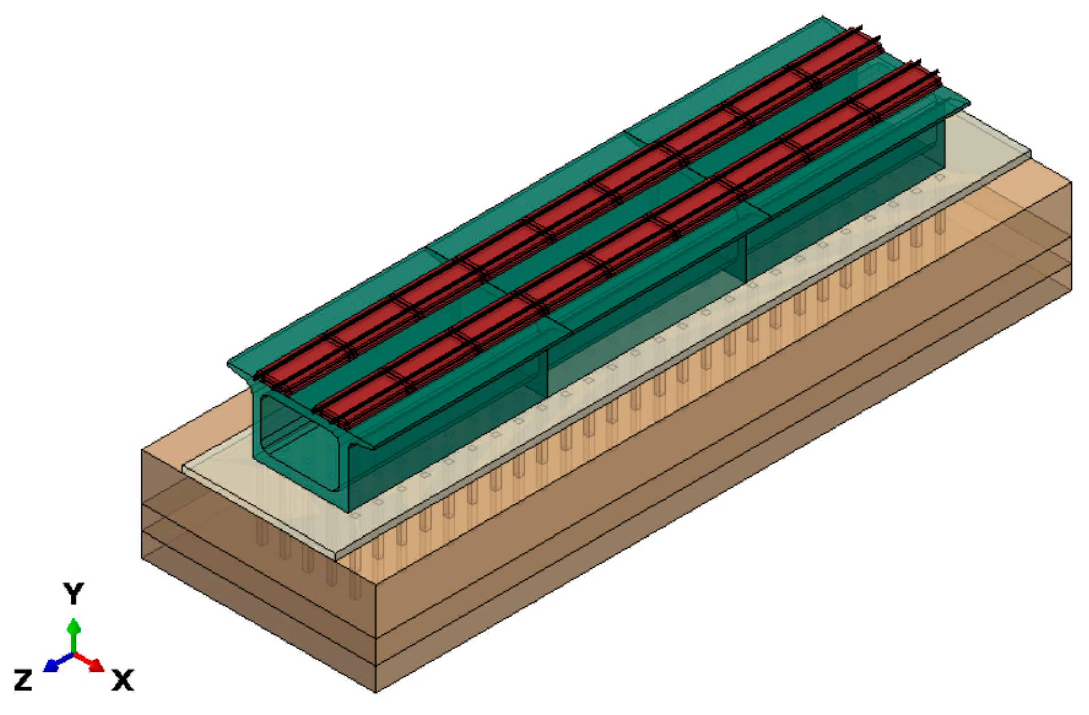
Referring to the pertinent literature [20,21], this study takes into account the interaction between the box-type subgrade and the track structure over it under seismic actions, which influences the dynamic response of the subgrade. Based on the theory of coupled dynamics, a nonlinear interaction model of the ballastless track box-type subgrade is established. The foundation at the bottom is simulated with a six-spring system [22,23], as shown in Figure 2. Utilizing nonlinear time–history analysis, the present study investigates the dynamic response of the box-type subgrade under seismic actions.
Existing research [24,25] has indicated that for finite element analysis models solved directly, under the same integration method and time step conditions, the acceleration input mode achieves better accuracy compared to the displacement input mode. Therefore, for this system, by transforming the seismic load into an acceleration time–history curve and applying it to the system, the time–history analysis equations of each component under seismic action are presented in Equation (1) below, which can be solved using the Newmark method:
M { z . . ( t ) } + C { z . ( t ) } + K { z ( t ) } = M { z . . g ( t ) }
In Equation (1), { z . . ( t ) } , { z . ( t ) } , and { z ( t ) } represent the acceleration, velocity, and displacement vector arrays of the respective components relative to the base, respectively.

3.1. Finite Element Model

Based on the theory, a finite element model is established using the nonlinear finite element software ABAQUS (v.2018). The model utilizes the domestically developed CRTS Type-III slab track system in China, which consists of rails, fasteners, track slabs, self-compacting concrete, and base plates from top to bottom. This paper conducts a refined modeling of the ballastless track, where each track component is meshed with 8-node solid elements (C3D8R), reinforcement is simulated with T3D2 elements, and fasteners are of the Type WJ-8 with a spacing of 0.63 m. Considering the significant displacements that structures may undergo under seismic actions, nonlinear fasteners are employed for simulation. The force–displacement relationships of the fasteners in various directions are as follows [26]:
The longitudinal force–displacement relationship can be expressed as follows:
r L = 12 x 24 sign x | x | 2 mm | x | > 2 mm
where rL is the longitudinal resistance of the fastener, kN; x is the relative displacement between the rail and the bearing plate, mm.
The lateral resistance of the fastener is represented by the test-fitted results as follows:
r H = 4.5 x 9 sign x | x | 2 mm | x | > 2 mm
In the above equation, rH is the lateral resistance of the fastener, kN; x is the relative displacement between the rail and the sleeper, mm.
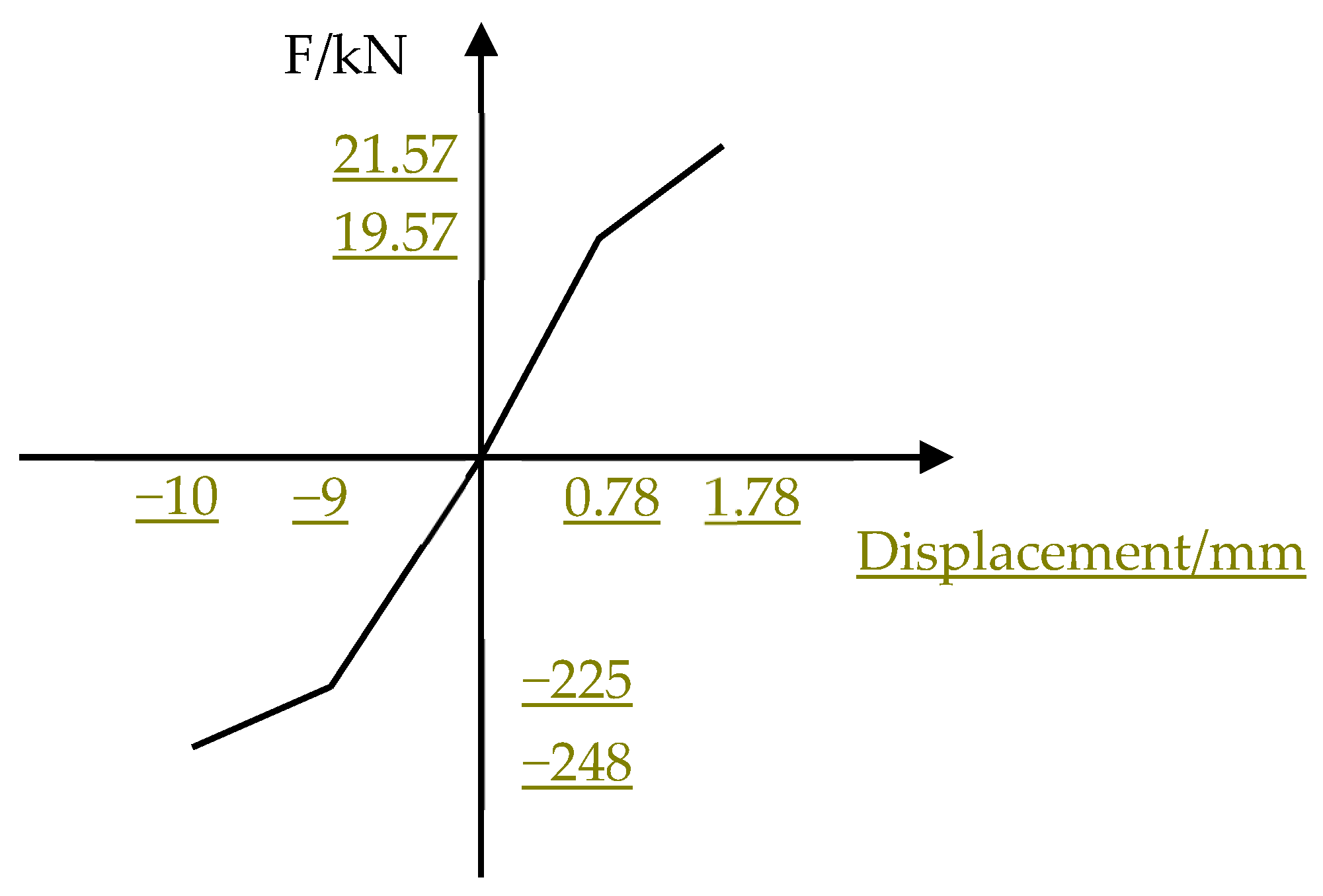
The vertical stiffness of the fastener depends on the loading condition of the fastener, as well as the vertical stiffness of the pad and the clip. The force–deformation curve of the fastener in the vertical direction is presented in Figure 3.
In practical engineering, a door-type reinforcement bar is utilized between the track slab and the self-compacting concrete layer to ensure a rigid connection; thus, a tied constraint is applied in the simulation, and surface-to-surface contact is employed between the self-compacting concrete and the base plate. The contact between the reinforcements and the track structure uses the embedding feature in the software. The specific parameters derived from the dimensions and arrangement of the CRTS Type-III slabs on bridges are delineated in Table 4 below, and the model is constructed in Figure 4.
As shown in Figure 5, the substructure of the track consists of a box-type subgrade and a CFG pile foundation in sequence [27,28]. The base plate is connected to the box-type subgrade through pre-embedded reinforcement bars, and a tie constraint is applied in the simulation [29]. The cross-sectional dimensions of the box-type subgrade structure are shown in Figure 6, and an element mesh simulation is performed using 8-node solid elements (C3D8R). The bottom is in surface-to-surface contact with the foundation, with a friction coefficient taken as 0.3 based on the relevant literature [30,31], and the pile foundation is modeled by the six-spring system, with the spring stiffness calculated using the m-method [32].

3.2. Analysis of the Self-Vibration Characteristics of Box-Type Subgrade Structures

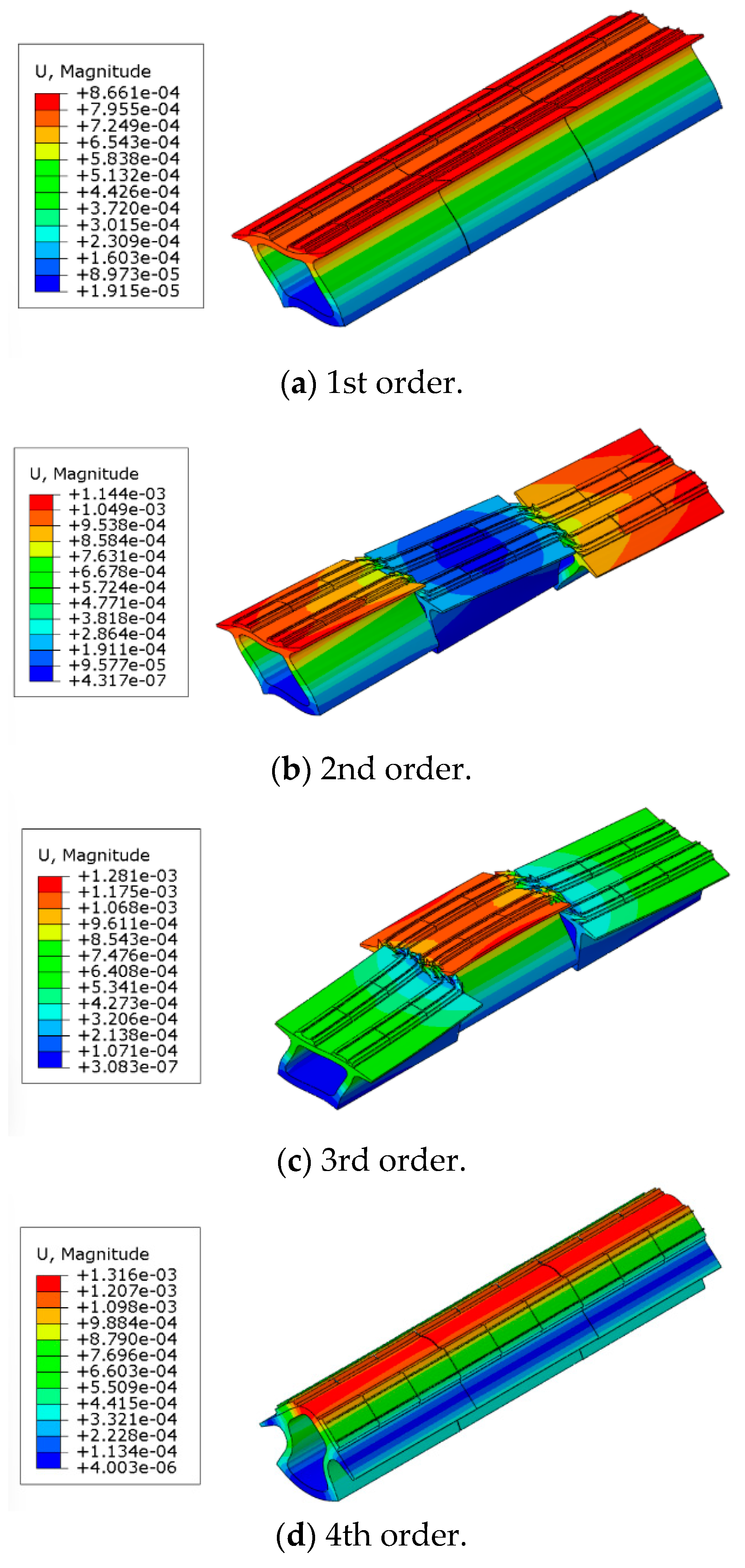
Based on the established model, the first ten vibration modes of the self-vibration characteristics of the box-type subgrade were calculated, as shown in Table 5. It can be observed that the lower-order vibration modes of the box-type subgrade are primarily characterized by the lateral deformation of the subgrade, indicating that the lateral vibration of the bridge is more likely to be excited during an earthquake. Starting from the fourth order, the vertical vibration modes of the box-type subgrade become significant. Due to space limitations, this paper presents the mode shape cloud diagrams of the first four orders, as illustrated in Figure 7. The rail nodes at the structural joints of the box-type subgrade are subjected to complex forces such as bending and torsion, representing the weak points of the structure under seismic action.
Comparing the natural vibration frequencies of the box-type subgrade with those measured by Yang et al. [33] using the environmental micro-vibration method and the drop-weight method on the Zhangjiayuanzi bridge (24 m + 32 m + 32 m), the horizontal and vertical natural vibration frequencies are contrasted, as shown in Table 6. The Zhangjiayuanzi bridge is a simply supported bridge with box beam sections, including spans of 24 m and 32 m. It can be observed that the vertical natural vibration frequencies of the box-type subgrade are higher than those of commonly used span bridges in China, while the horizontal natural vibration frequencies are lower than those of commonly used span bridges.

3.3. Seismic Wave Input

Earthquakes are caused by violent movements in the earth’s crust, and unlike traditional mechanical load characteristics, they propagate and load in the form of acceleration. Due to the small span of the box-type subgrade structure, the effects of wave propagation and non-uniform excitation can be neglected. The direct acceleration method is selected to input the seismic wave excitation at the bottom of the box-type subgrade with a stiffness spring unit. The structure employs Rayleigh damping, with the damping ratio ξ taken as 0.05, and the damping coefficients α and β are calculated according to Equation (4) below.
α = 2 h ω 1 ω 2 ω 1 + ω 2 β = 2 h 1 ω 1 + ω 2
where ω1 and ω2 represent the first-order frequency and the primary frequency contributing to the longitudinal vibration mode of the structure.
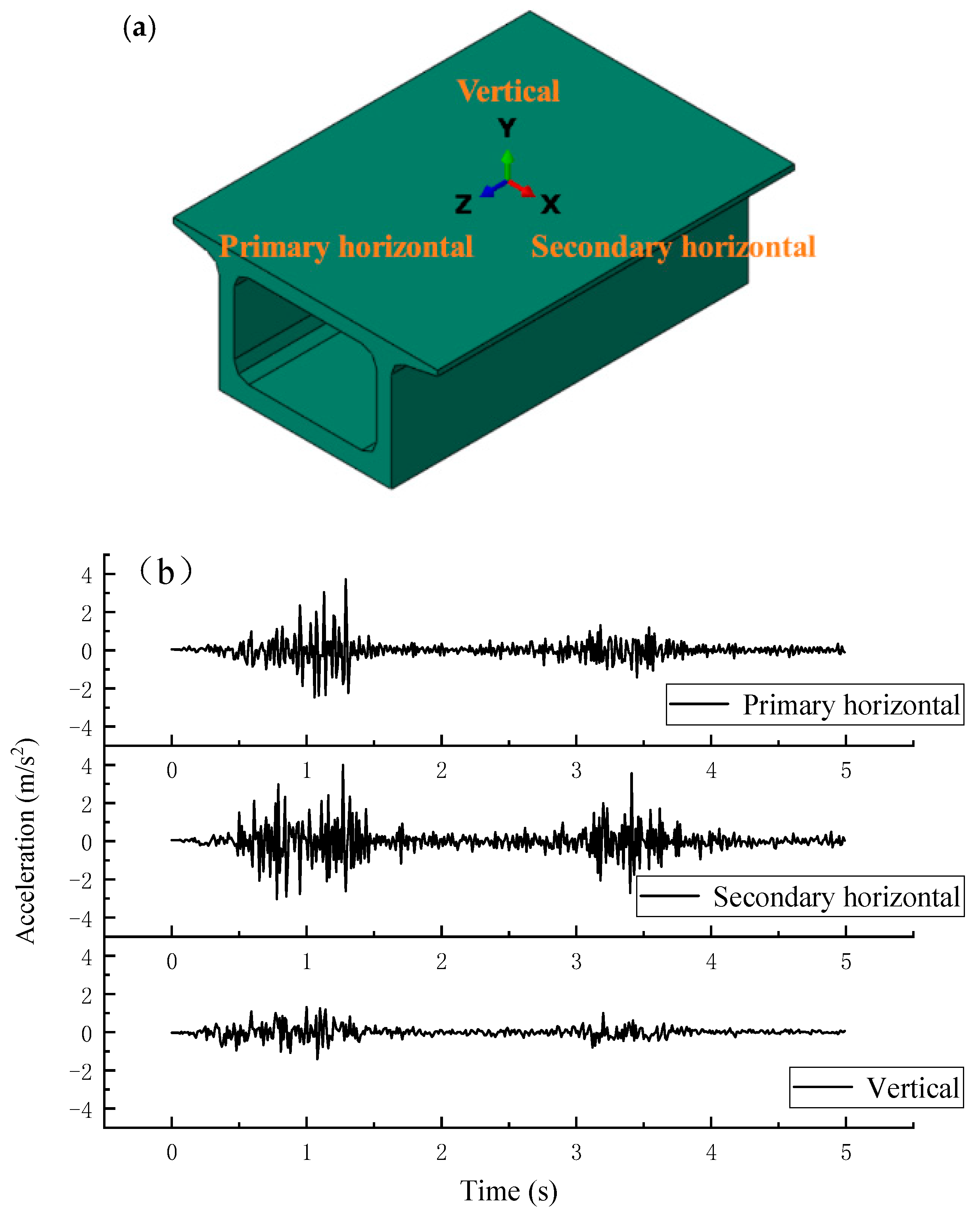
This paper selects the classic Wenchuan Wolong earthquake wave for analysis. To approximate the actual state of seismic waves, the input of multi-dimensional seismic waves is considered [34]. In the 3D track model, the direction along the longitudinal axis of the box-type subgrade is defined as the primary horizontal direction; the direction perpendicular to the longitudinal axis of the box-type subgrade is defined as the secondary horizontal direction, and the direction perpendicular to the track plane is defined as the vertical direction, as shown in Figure 8a. Considering the computational time cost, the seismic wave near the peak value of vibration acceleration is truncated, and values are extracted at certain time intervals. Referring to the provisions of Clause 7.2.4 of the “Seismic Design Code for Railway Engineering”, the actual seismic wave is adjusted for peak value as per Equation (5), and the adjustment ratio is based on the “Seismic Design Code for Buildings” set as the primary horizontal direction: secondary horizontal direction: vertical direction = 1:0.85:0.65. Figure 8b below shows the seismic wave curve adjusted to 0.4 g.
a h ' ( t ) = A g A max a h ( t )
Here, ah′(t) is the adjusted horizontal ground motion acceleration time–history curve; ah(t) is the horizontal ground motion acceleration time–history curve before adjustment; Ag is the maximum ground motion value determined according to the seismic fortification intensity in the specification; Amax is the maximum value of the acceleration time–history curve recorded in the actual seismic wave data.

4. Seismic Response of Box-Type Subgrade

4.1. System Dynamic Response Characteristics Under Multi-Dimensional Seismic Coupling

4.1.1. Vibration and Response Analysis of Box Foundation Based on the Time–Frequency Domain Method

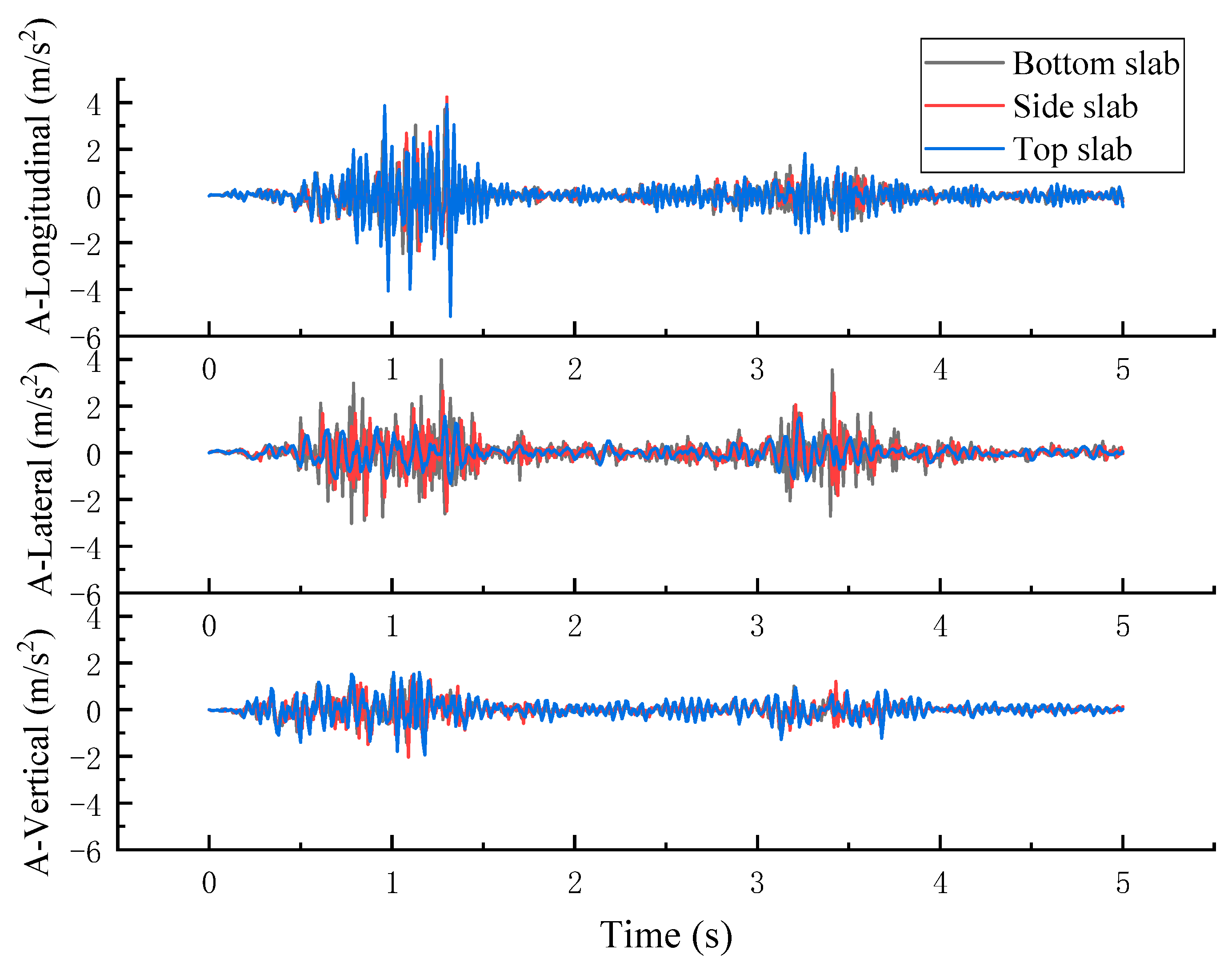
To explore the vibration characteristics of box-type subgrades under the coupling action of multi-dimensional earthquakes, this paper analyzes the acceleration time–history changes at the top slab, the bottom slab, and the side slab of the box-type subgrade under the seismic action with a maximum design basic acceleration of 0.4 g (see Table 1) in Figure 9. Compared with Figure 8b, the acceleration curve of the box-type subgrade is basically consistent with the waveform of the input seismic wave. In addition, the vibration amplification factors of each component of the box-type subgrade are statistically analyzed, that is, the ratio of the output to the input acceleration peak value, as shown in Table 7. It can be observed that the vibration peak value of the bottom slab of the box-type subgrade is consistent with the input acceleration peak value [35], while the vertical acceleration amplification effect of the side slab of the box-type subgrade is the most significant, with an amplification factor reaching a value of 1.44. According to the research results of Liu et al. [36], the horizontal acceleration amplification factor of the single-bridge model of traditional simply supported beams under the Wenchuan earthquake with a magnitude of 0.1 g has already reached a value as high as 2.1. The seismic amplification factor of the box-type subgrade is relatively small, indicating that the seismic performance of the box-type subgrade is better than that of commonly used bridges in strong earthquakes.
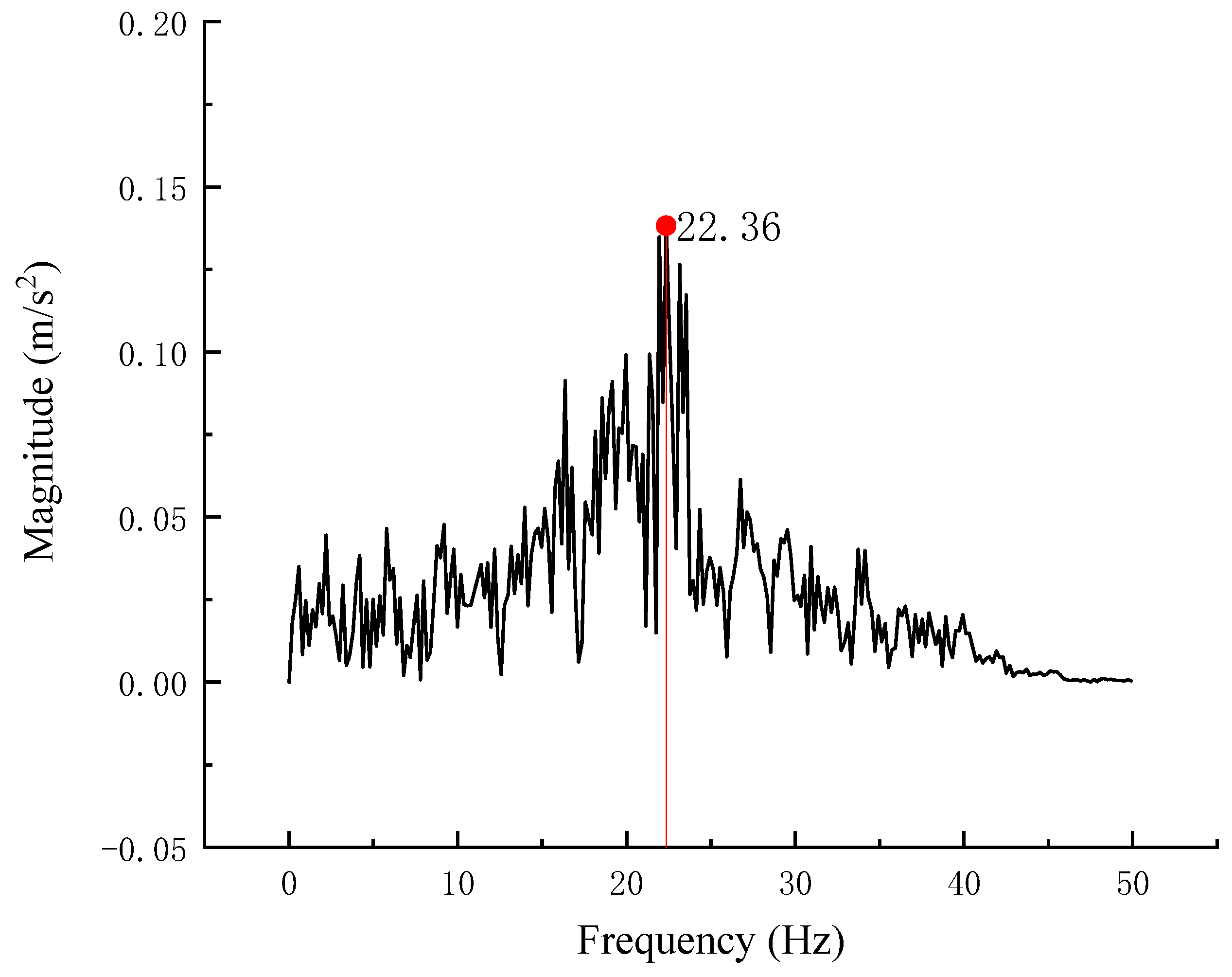
To further investigate the vibration characteristics of the box-type subgrade structure, the vertical acceleration of the side panel of the box-type subgrade with the largest amplification factor was extracted, and its Fourier transform was performed to obtain a spectral diagram, as shown in Figure 10. The peak of the vibration is at 22.36 Hz, which is close to the vertical natural frequency of the box-type subgrade of 23.10 Hz in 6 of Section 3 mentioned earlier, indicating that the box-type subgrade has resonated with the input vertical seismic wave [37]. However, compared with traditional simply supported beams, the amplification factor is relatively small, indicating good seismic performance of the box-type subgrade.
China has established an earthquake emergency response system for railway transportation to prevent or mitigate the hazards of earthquakes to the safety of railway transportation. Currently, the alarm method in China adopts a threshold-triggered approach based on ground motion parameters (early warning system) [38]. The acceleration of the box-type subgrade’s side panel differs significantly from the original ground motion response spectrum values, but the structural period corresponding to the peak of the curve is essentially consistent, both being 0.034 s in Figure 11. This indicates that with the input of the original ground motion, the frequency characteristics corresponding to the acceleration response time–history of the beam surface have not changed. Therefore, in subsequent studies on the earthquake alarm threshold for the box-type subgrade system, the basic parameters of the original acceleration record of the earthquake can be used to improve the prediction accuracy [39,40].

4.1.2. Force and Deformation Characteristics of Box-Type Subgrade

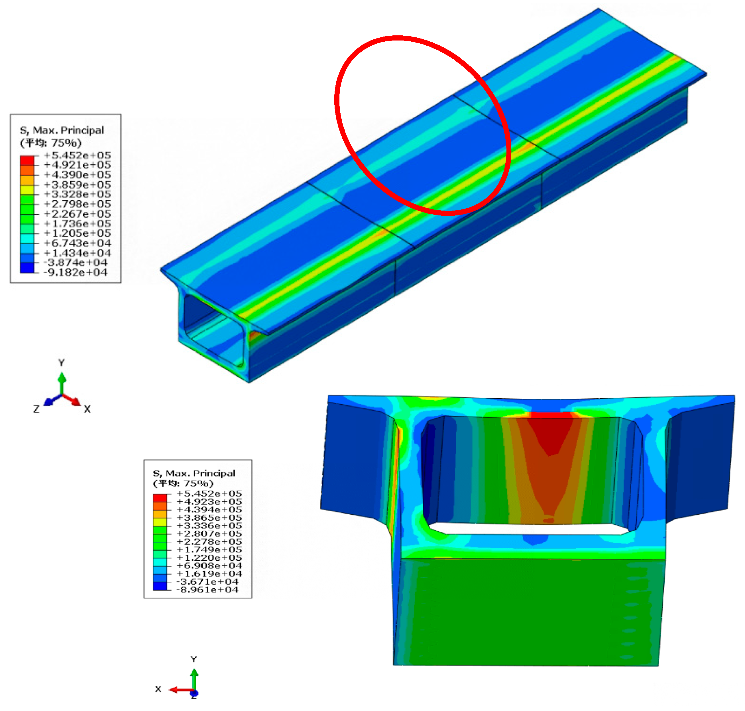
To investigate the force characteristics of the box-type subgrade structure, the force cloud diagram of the box-type subgrade at the time of maximum amplification effect is presented. To study the force and deformation conditions of the box-type subgrade structure in actual applications and to avoid the influence of boundary effects, the mid-span box-type subgrade structure is analyzed, as shown in Figure 12. It can be observed from the figure that under seismic action, the maximum principal stress in the box-type subgrade is compressive on the top slab surface and tensile on the bottom surface, with the maximum tensile stress being 0.542 MPa, which is within the structural limit range. The side walls are eccentrically compressed, with tensile stress presented on the outer side at the connection with the top slab, but it does not exceed the limit; the bottom slab is under overall compression. Under the maximum design basic acceleration of an earthquake, the stress in each component of the box-type subgrade is far below the design strength and is maintained in a linear elastic state, achieving the design performance objectives and complying with China’s seismic fortification standard of “no damage in minor earthquakes, repairable after moderate earthquakes, and no collapse in major earthquakes”.
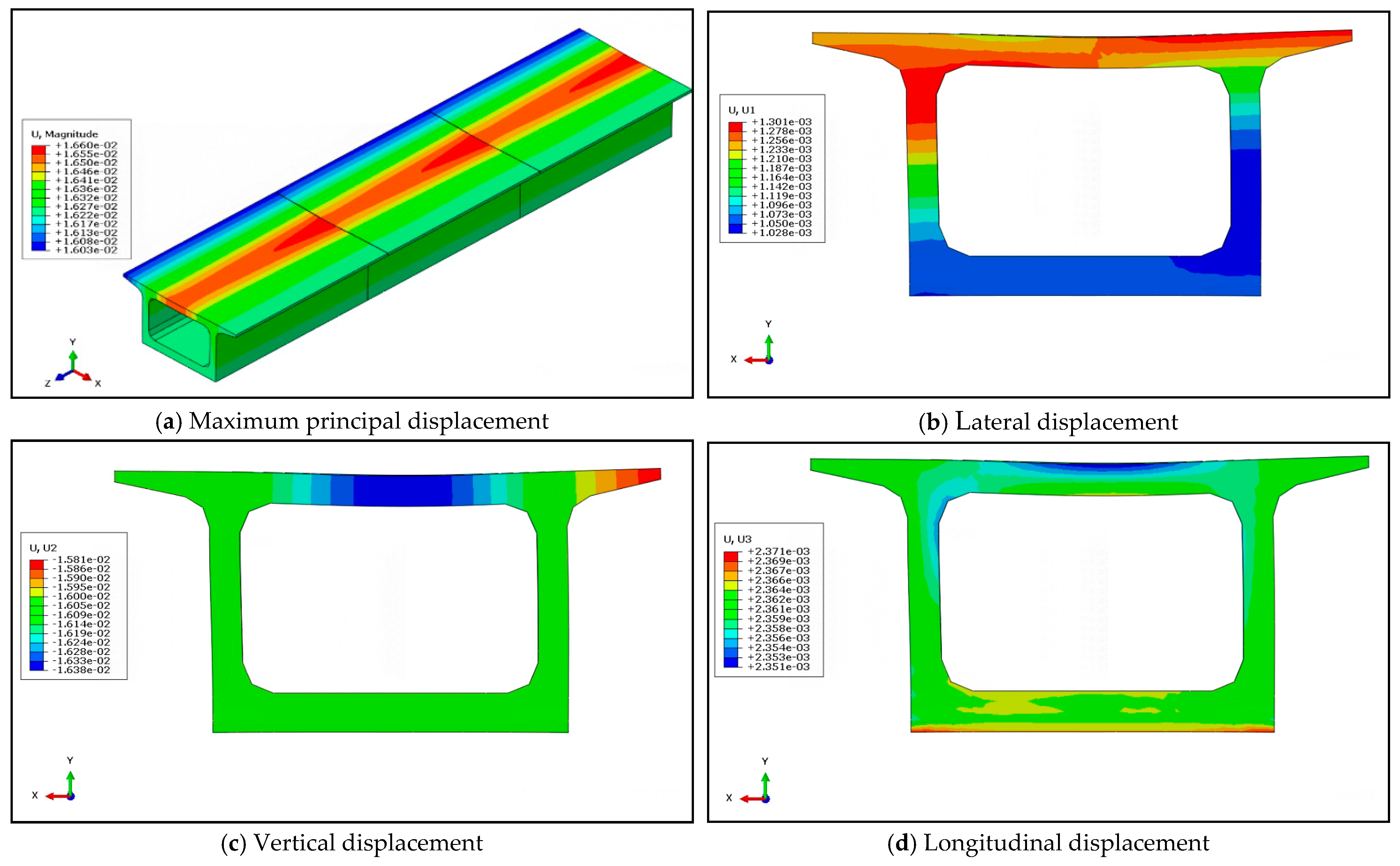
To explore the deformation characteristics of the box-type subgrade structure, the deformation cloud diagram of the box-type subgrade at the time of maximum amplification effect is presented. As shown in Figure 13a, the deformation at the structural joints of the box-type subgrade is more pronounced. The deformation cloud diagrams of the most unfavorable cross-sections in various directions of the box-type subgrade are extracted, as shown in Figure 13b–d. Under the coupled action of multi-dimensional seismic forces, the box-type subgrade is primarily dominated by vertical deformation, which is concentrated in the middle of the top slab. Numerically, the maximum range of deformation of the box-type subgrade is only 0.57 mm, indicating that the structure itself undergoes little relative deformation under seismic action, i.e., no significant bending deformation occurs, suggesting that the box-type subgrade has good adaptability.
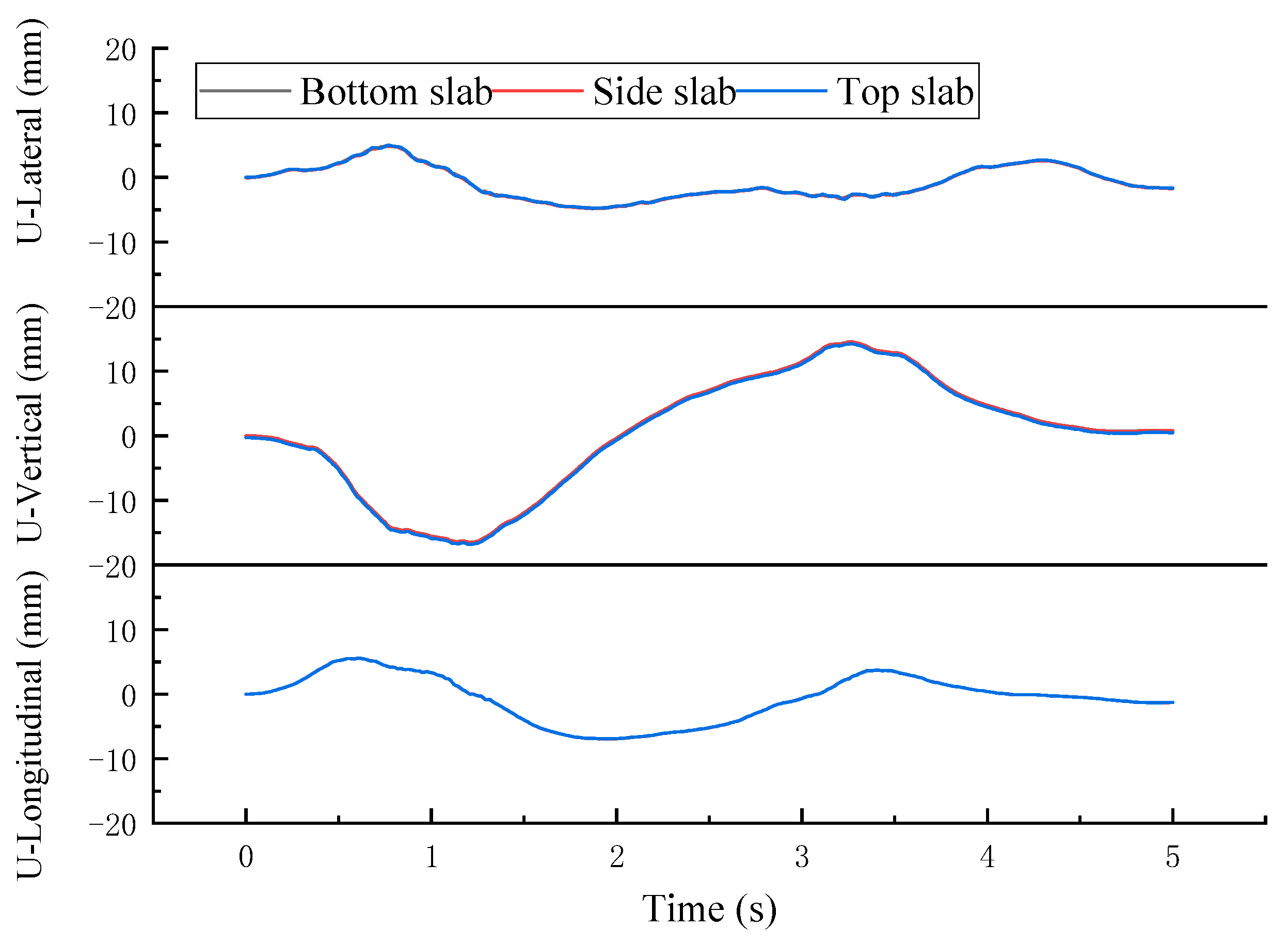
To further investigate the deformation characteristics of each component of the box-type subgrade, the deformation time–history curves of the bottom slab, side walls, and top slab of the box-type subgrade in each direction were extracted, as shown in Figure 14. It can be observed that the displacement time–history curves of each component of the box-type subgrade in all directions essentially coincide, indicating that under seismic action, the box-type subgrade primarily undergoes rigid body motions.

4.2. Dynamic Response of Box Culvert Foundations Under Different Earthquake Intensities

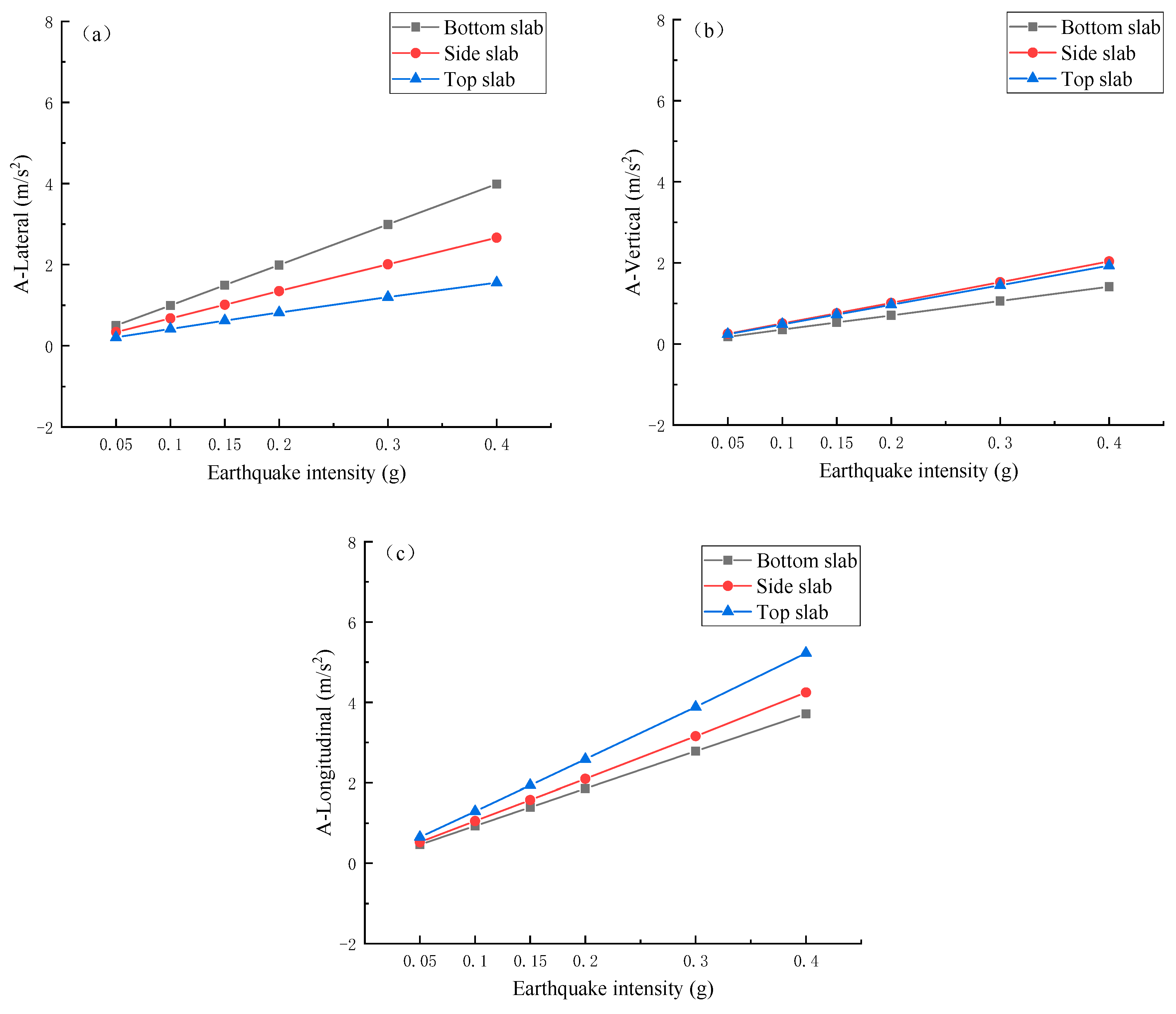
Based on the aforementioned analysis, different seismic fortification intensities from 1 under the design earthquake action are selected as calculation scenarios to explore the impact of seismic fortification intensity on the vibration response of the box-type subgrade. As a first step, the peak acceleration values of each component of the box-type subgrade in different directions under different seismic fortification intensities are statistically analyzed, as shown in Figure 15. As the seismic intensity increases, the acceleration of each component of the box-type subgrade in all directions increases linearly. Among them, the increase in the transverse and longitudinal directions is relatively large, while the increase in the vertical direction is relatively small, indicating that under multi-dimensional seismic actions. The seismic intensity has a greater impact on the transverse and longitudinal accelerations of the box-type subgrade and a relatively smaller impact on the vertical acceleration.
To investigate the impact of seismic intensity on the forces experienced by box-type subgrades, the maximum principal stresses of the box-type subgrade structure with different seismic intensities were extracted, as shown in Figure 16. It can be observed that as the seismic intensity increases, the forces on the box-type subgrade structure increase nonlinearly. The growth is relatively slow under the action of low-intensity earthquakes, and the force on the box-type subgrade structure accelerates after the designed basic acceleration peak exceeds 0.2 g. Therefore, when conducting high-intensity seismic-resistant design for box-type subgrades, special attention should be given to the accelerated force damage of the box-type subgrade.
Subsequently, the maximum displacements in each direction of the box-type subgrade structure with different seismic intensities were extracted, as shown in Figure 17. As the seismic intensity increases, the deformation of the box-type subgrade structure increases linearly, which is consistent with the previous speculation that the box-type subgrade undergoes rigid body motion under seismic action. Among the displacements in all directions, the vertical displacement is the main component, while horizontal displacement is relatively small and grows the slowest. This indicates that the risk of lateral sliding of the box-type subgrade is relatively low due to its own weight under seismic action.

5. Conclusions

The box-type subgrade is a novel subgrade structure proposed in China in recent years and is currently in the early stages of research. This paper takes the lead in establishing a nonlinear integrated spatial dynamic model of ballastless track and box-type subgrade and systematically analyzes the seismic response characteristics of the box-type subgrade structure under multi-dimensional seismic actions. A comparative analysis with the seismic response of commonly used bridges is also conducted. The study outcomes are mentioned below:
(1)
Due to the contact connection between the box-type subgrade and the underlying foundation, the vibration response of the box-type subgrade under seismic action is primarily the rigid body motion. The deformation of various components, such as the top slab, side walls, and bottom slab, of the box-type subgrade under seismic action is small. Overall, it can meet the seismic defense requirements of “no damage in minor earthquakes, repairable in moderate earthquakes, and no collapse in major earthquakes”.
(2)
Under seismic action, there is tensile stress concentration at the contact area between the bottom of the top slab and the side walls of the box-type subgrade, but it is far below the designed strength value, with the bottom slab being in compression. In terms of vibration amplification factors, the acceleration amplification factor of the box-type subgrade is just 1.44 at resonance. Compared with traditional simply supported beams, the seismic amplification factor of the box-type subgrade is relatively small, indicating better adaptability in strong earthquakes.
(3)
The analysis shows that the frequency characteristics of the acceleration response time–history curve of the box-type subgrade under seismic action are basically consistent with the input seismic wave; therefore, it is suggested that the seismic alarm threshold setting for the box-type subgrade system uses the original acceleration ground motion parameters.
(4)
With an increase in seismic intensity, the vibration and deformation of the box-type subgrade change linearly. The deformation occurs mainly in the vertical displacement, with the horizontal displacement being relatively small and the growth rate relatively low. However, the structural force increases nonlinearly, exhibiting a slower growth at low seismic intensities. Once the design basic acceleration peak crosses 0.2 g, the force on the box-type subgrade structure increases significantly, and the rate of damage accelerates.

Author Contributions

Y.-Y.C.: conceptualization, software, supervision, methodology, visualization, writing—review and editing. H.X.: formal analysis, funding acquisition, methodology, investigation, writing—original draft. X.-G.S.: data curation, methodology. M.M.N.: writing—review and editing. S.-J.G.: data curation. B.-E.L.: methodology. M.M.N.: writing—review and editing. All authors have read and agreed to the published version of the manuscript.

Funding

This work was supported by the Open Project Fund of the National Engineering Research Center for Digital Construction and Evaluation Technology of Urban Rail Transit (Grant No. 2023JS01) and the Basic Scientific Research Operating Expenses of Central Universities (Science and technology leading talent team project) (Grant No. 2022JBXT010), and the National Key Research and Development Program of China (Grant No. 2023YFB2604302).

Data Availability Statement

The original contributions presented in this study are included in the article. Further inquiries can be directed to the corresponding author.

Conflicts of Interest

Authors Xu-Guo Song and Shuai-Jie Guo were employed by the company China Railway Design Corporation Limited. The remaining authors declare that the re-search was conducted in the absence of any commercial or financial relationships that could be construed as a potential conflict of interest.

References

  1. GB 18306-2015; China’s Ground Motion Parameter Zoning Map. Standard Press: Beijing, China, 2015.
  2. Jiang, L.; Kang, X.; Li, C.; Shao, G. Earthquake response of continuous girder bridge for high-speed railway: A shaking table test study. Eng. Struct. 2019, 180, 249–263. [Google Scholar] [CrossRef]
  3. Yu, L.; Zhu, Z.; Qin, Y.; Wang, X.; Wang, Y.; Zheng, W. Study on the settlement limit of high-speed railway box subgrade. J. Railw. Sci. Eng. 2023, 20, 3203–3216. [Google Scholar] [CrossRef]
  4. Zongyu, Z.; Lei, Y.; Dijia, T.; Junjie, H.; Qian, S. Analysis of static and dynamic characteristics of high-speed railway flange frame box subgrade. Subgrade Eng. 2023, 4, 6–12. [Google Scholar] [CrossRef]
  5. Xie, H.; Xiao, S. Calculation method for high-fill box-type embankment structures of railways. J. Shandong Univ. Eng. Sci. 2022, 4, 166–174. [Google Scholar]
  6. Nilimaa, J. Smart materials and technologies for sustainable concrete construction. Dev. Built Environ. 2023, 15, 100177. [Google Scholar] [CrossRef]
  7. Tullini, N.; Traili, A.; Baraldi, D. Stability of slender beams and frames resting on 2D elastic half-space. Arch. Appl. Mech. 2013, 83, 467–482. [Google Scholar] [CrossRef]
  8. Tezzon, E.; Tullini, N.; Minghini, F. Static analysis of shear flexible beams and frames in adhesive contact with an isotropic elastic half-plane using a coupled fe-bie model. Eng. Struct. 2015, 104, 32–50. [Google Scholar] [CrossRef]
  9. Baraldi, D.; Tullini, N. Incremental analysis of elastoplastic beams and frames resting on an elastic half-plane. J. Eng. Mech. 2017, 143, 04017101. [Google Scholar] [CrossRef]
  10. Mylona, E.K.V.; Sextos, A.G.; Mylonakis, G.E. Rotational seismic excitation effects on CIDH pile-supported bridge piers. Eng. Struct. 2017, 138, 181–194. [Google Scholar] [CrossRef]
  11. Liu, Z.-N.; Chen, X.-C.; Zhang, Y.-L. Longitudinal seismic response of ballastless railway bridges considering traveling wave effect. J. Vib. Shock 2020, 39, 142–149. [Google Scholar]
  12. Toyooka, A.; Ikeda, M.; Yanagawa, H.; Kataoka, H.; Iemura, H.; Murata, K. Effects of track structure on seismic behavior of isolation system bridges. Q. Rep. RTRI 2005, 46, 238–243. [Google Scholar] [CrossRef]
  13. Zhang, Y.-L.; Yang, S.-J.; Chen, X.-C. Seismic response analysis of high-speed railway bridges based on rail-bridge integrated model. Bridge Constr. 2016, 46, 23–28. [Google Scholar]
  14. Yang, M.-G.; Meng, D.-L.; Dai, L.-Y. Transverse seismic pounding effect for simply-supported girder bridges of high-speed railway considering track constraint. J. Cent. South Univ. Sci. Technol. 2018, 49, 916–924. [Google Scholar]
  15. Zhang, P.-F.; Cai, K.; Wang, C.-L.; Lei, X.-Y. Dynamic response of CRTSIII slab ballastless track system on bridge with multi-dimensional earthquake action. Sci. China Technol. Sci. 2024, 54, 924–939. [Google Scholar]
  16. Ai, Z.-L. Study of nonlinear time-history analysis on railway portal pier. J. Railw. Eng. Soc. 2014, 31, 61–66. [Google Scholar]
  17. Sun, Z.-F. Design and research of large span steel box portal pier for high speed railway. J. Railw. Eng. Soc. 2019, 36, 43–47. [Google Scholar]
  18. GB50111-2006; Code for Seismic Design of Railway Engineering. Plan Press: Beijing, China, 2009.
  19. Liu, Z.-W. Research on seismic performance and design method for high-speed railway bridges based on track-bridge integrated model. Chin. J. Rock Mech. Eng. 2020, 39, 1080. (In Chinese) [Google Scholar]
  20. Yan, B.; Kuang, W.-F.; Yu, L.-M.; Luo, B.-F. Seismic response characteristics of high-speed railway portal piers, bridge-track systems. J. Cent. South Univ. Nat. Sci. Ed. 2023, 54, 3544–3550. [Google Scholar]
  21. Maleska, T.; Beben, D.; Vaslestad, J.; Sergei Sukuvara, D. Application of EPS Geofoam below Soil–Steel Composite Bridge Subjected to Seismic Excitations. J. Geotech. Geoenvironmental Eng. 2024, 150, 12674. [Google Scholar] [CrossRef]
  22. Lu, R. Comparative Analysis of Simplified Seismic Calculation Methods for Pile Group Bridge Structures. Master’s Thesis, Tongji University, Shanghai, China, 2001. [Google Scholar]
  23. Lu, J.; Chen, X.; Ding, M.; Ma, H.; Zhang, X. Research on simplified seismic calculation models for railway gravity piers. Vib. Shock 2021, 9, 71–76. [Google Scholar] [CrossRef]
  24. Du, X.-T.; Xia, H.; Yu, Z. Research on the Excitation Input Mode in Seismic Analysis of Bridges. J. Railw. Sci. Eng. 2011, 33, 86–90. [Google Scholar]
  25. Ding, Y.; Zhang, G.; Zhao, X.; Lu, Z.; Li, X. Shear performance of horizontally curved steel box bridge girders under hydrocarbon fire exposure conditions: Numerical investigation and design implications. Thin-Walled Struct. 2024, 205, 112479. [Google Scholar] [CrossRef]
  26. TB0015-2012; Specifications for the Design of Railway Track without Joints. Railway Publishing House: Beijing, China, 2012.
  27. Zhang, Y.; Xu, J.; Liu, C.; Chen, X. Seismic response of railway bridge pile foundations under cap-pier-soil interaction. J. Railw. Eng. Soc. 2020, 5, 30–35. [Google Scholar]
  28. Gao, G.; Pan, T.; Geng, J.; Chen, S. Vibration characteristics of pile-net composite foundation under the combined action of earthquakes and high-speed trains. Noise Vib. Control. 2024, 1, 7–14. [Google Scholar]
  29. Luo, Y.; Liu, X.; Cui, J.; Wang, H.; Huang, L.; Zeng, W.; Zhang, H. Lifetime fatigue cracking behavior of weld defects in orthotropic steel bridge decks: Numerical and experimental study. Eng. Fail. Anal. 2025, 167, 108993. [Google Scholar] [CrossRef]
  30. Embaby, M.; El Naggar, M.H. Experimental and numerical investigation for steel shear panels of modular bridge. J. Constr. Steel Res. 2024, 219, 108743. [Google Scholar] [CrossRef]
  31. Nicoletti, R.S.; Rossi, A.; de Souza AS, C.; Martins, C.H. Numerical assessment of effective width in steel-concrete composite box girder bridges with partial interaction. Eng. Struct. 2021, 239, 112333. [Google Scholar] [CrossRef]
  32. Wei, B.; Yang, T.-H.; Jiang, L.-Z. The Influence of the Refinement of Track Structure Modeling on the Seismic Vulnerability of High-Speed Railway Continuous Beam Bridges. Eng. Mech. 2018, 35, 16–23+51. [Google Scholar]
  33. Yang, Y.-Q.; Yao, J.-C.; Liu, P.-H.; Ke, Z. Experimental Study on Dynamic Performance of Ballastless Track Railway Bridges with Common Spans. China Railw. Sci. 2008, 29, 47–52. [Google Scholar]
  34. Yan, B.; Liu, S.; Dai, G.-L.; Pu, H.; Tang, J.-F. Nonlinear Interaction between Bridge and Ballastless Track under Multi-Dimensional Seismic Actions. J. Railw. Eng. 2016, 38, 74–80. [Google Scholar]
  35. Zhan, Y.-X.; Jiang, G.-L.; Wei, Y.-X. Dynamic Response Analysis of Ballastless Track Pile Slab Structure Subgrade under Seismic Load. China Railw. Sci. 2006, 6, 22–26. [Google Scholar]
  36. Liu, Z.; Guo, E.-D.; He, Q.; Shengjian, L. Seismic Response Analysis of High-Speed Railway Coupled Vehicle-Bridge System. Earthq. Eng. Eng. Vib. 2015, 35, 119–124. [Google Scholar] [CrossRef]
  37. Meng, X. Analysis of Vertical Resonance Conditions for Simplified Supported Box Beams with Common Spans in High-Speed Railways. Vib. Shock 2019, 38, 19–24+32. [Google Scholar] [CrossRef]
  38. Xiao, W.-J. National Earthquake Intensity Rapid Reporting and Early Warning Project. Disaster Prev. Mitig. 2023, 1, 18–23. [Google Scholar]
  39. Lin, L.; Li, C.-H.; Wei, Y.-M. Selection of Computational Parameters for Earthquake Intensity Rapid Reporting and Early Warning System. J. Heilongjiang Coll. Eng. 2019, 33, 20–23. [Google Scholar] [CrossRef]
  40. Wang, Y.; Xiao, H.; Zhang, Z.; Guo, X.; Liu, Q. Self-supervised representation learning of metro interior noise based on variational autoencoder and deep embedding clustering. Comput.-Aided Civ. Infrastruct. Eng. 2024, 1–20. [Google Scholar] [CrossRef]
Figure 1. Chinese earthquake records and railway lines.
Applsci 14 11899 g001
Figure 2. Model of ballastless track and box subgrade.
Applsci 14 11899 g002
Figure 3. Vertical resistance–deformation curve of fastener.
Applsci 14 11899 g003
Figure 4. Finite element model diagram of ballastless track.
Applsci 14 11899 g004
Figure 5. Coupled finite element model diagram of box-type subgrade.
Applsci 14 11899 g005
Figure 6. Schematic diagram of the geometric dimensions of box-type subgrade.
Applsci 14 11899 g006
Figure 7. Box-type subgrade modal shape.
Applsci 14 11899 g007
Figure 8. Model input seismic waves. (a) The directions of seismic wave input. (b) Seismic wave acceleration curve.
Applsci 14 11899 g008
Figure 9. Time–history acceleration curve for each component of box-type subgrade.
Applsci 14 11899 g009
Figure 10. Vertical acceleration spectrum of box subgrade roof.
Applsci 14 11899 g010
Figure 11. Acceleration response spectrum curve.
Applsci 14 11899 g011
Figure 12. Cloud map of box-type subgrade force cloud map.
Applsci 14 11899 g012
Figure 13. Cloud map of box subgrade deformation.
Applsci 14 11899 g013
Figure 14. Displacement time–history curve of each component for box-type subgrade.
Applsci 14 11899 g014
Figure 15. Peak acceleration of box-type subgrade at various earthquake intensities. (a) Lateral acceleration. (b) Vertical acceleration. (c) Longitudinal acceleration.
Applsci 14 11899 g015
Figure 16. Maximum principal stress of box subgrade at various earthquake intensities.
Applsci 14 11899 g016
Figure 17. Maximum principal displacement of box subgrade at various earthquake intensities.
Applsci 14 11899 g017
Table 1. Seismic fortification intensity.
Fortification Intensity6789
Frequent Earthquakes0.02 g0.04 g0.05 g0.07 g0.10 g0.14 g
Design Earthquakes0.05 g0.10 g0.15 g0.20 g0.30 g0.40 g
Rare Earthquakes0.11 g0.21 g0.32 g0.38 g0.57 g0.64 g
Table 2. Seismic performance standards for railway box-type subgrades.
Seismic Performance StandardsStructural Working ConditionsRemarks
Performance Requirement INormal Operating StateThe structure can be considered an elastic system, and under the expected seismic action, the structure generally suffers no damage or minor damage without interrupting traffic.
Performance Requirement IIInelastic Operating StateThe inelastic deformation of the structure or the damage to the structural system should be controlled within a repairable range. Under the expected seismic action, the structure should not suffer significant damage and can be a limited-speed operation open to traffic after repair.
Performance Requirement IIIElastoplastic Working PhaseThe structure undergoes significant inelastic deformation, but it should be controlled within the specified range. Under the expected seismic action, the structure may suffer considerable damage but should not collapse entirely. It can be a limited-speed operation open to traffic after emergency repair.
Table 3. Seismic fortification goals and analysis methods of railway engineering structures with different ground motion levels.
Seismic Ground Motion LevelFrequent EarthquakesDesign EarthquakesRare Earthquakes
StructuresBridgesSubgrades, retaining walls, tunnels, abutments, and connections between upper and lower bridge structuresBridges with reinforced concrete piers
Seismic Design
Objectives
Meet Seismic Performance Requirement IMeet Seismic Performance Requirement IIMeet Seismic Performance Requirement III
Analysis MethodsGeneral Bridges: Response Spectrum MethodStatic methodSimplified method for ductility design of reinforced concrete piers
Table 4. Ballastless track parameters.
NameDensity (kg/m3)Elastic Modulus (Pa)Poisson’s RatioDimensions (m)
Rebar78001.9 × 1090.3HRB400
Rail78502.1 × 10110.360 kg/m
Track Slab25003.6 × 10100.1672.5 × 2.0 × 5.6
Self-Compacting Concrete20003 × 1090.1672.5 × 0.9 × 5.6
Base Plate25003.25 × 10100.1672.95 × 2.0 × 5.65
Table 5. Natural frequency of box-type subgrade.
OrderFrequency (Hz)Box-Type Subgrade Deformation State
19.24Lateral deformation in the same direction
210.74Lateral deformation in opposite directions
313.84Lateral deformation in opposite directions
423.10Vertical deformation in the upward and downward directions
523.21Vertical torsional deformation
624.64Vertical torsional deformation
725.00Horizontal torsional deformation
826.15Horizontal torsional deformation
927.19Vertical torsional deformation
1027.50Vertical torsional deformation
Table 6. Comparative data for conventional single-span supported beams.
Beam StructureVertical Natural Frequency (Hz)Horizontal Natural Frequency (Hz)
16.99 m Box-Type Subgrade23.109.24
24 m Simply Supported Beam11.2521.34
32 m Simply Supported Beam8.0815.59
Table 7. Vibration amplification factor of each component of box-type subgrade.
Vibration Amplification FactorsLongitudinalTransverseVertical
Peak Value of Input Seismic Wave3.7143.9871.413
Bottom Slab (Peak Acceleration/Amplification Factor)3.714/13.987/11.413/1
Side Slab (Peak Acceleration/Amplification Factor)4.235/1.142.673/0.672.039/1.44
Top Slab (Peak Acceleration/Amplification Factor)5.151/1.391.559/0.391.945/1.38
Disclaimer/Publisher’s Note: The statements, opinions and data contained in all publications are solely those of the individual author(s) and contributor(s) and not of MDPI and/or the editor(s). MDPI and/or the editor(s) disclaim responsibility for any injury to people or property resulting from any ideas, methods, instructions or products referred to in the content.