1. Introduction
The demand for gears in the electric vehicle reducer and robot reducer industries is enormous, and the requirements of gear processing precision are becoming increasingly stringent. The machining efficiency and accuracy of skiving are high, and they have unique advantages in the machining of internal gears and coupling gears, with good application prospects. However, the primary limiting application of gear skiving is the rapid wear of skiving tools [
1,
2,
3].
Currently, there is relatively little research on the fundamental causes of skiving tool wear, making it difficult to accurately reveal the stress patterns during skiving and the chip formation mechanism.
This hinders the effective support of wear-resistant skiving tool and process design practices.
Thomas Bergs et al. [
4] used numerical penetration calculation methods to analyze the variation patterns of skiving chip thickness. Spath et al. [
5] studied the changes in tool working angles, cutting speed, and cutting thickness during the skiving process and examined tool wear characteristics through experimental methods. Klocke et al. [
6] investigated the changes in tool working angles and cutting thickness by analyzing the causes of tool wear. Schulze et al. [
7] used thermocouple methods to study the cutting heat during skiving and employed finite element methods to explore the chip formation mechanism. Nikolaos et al. [
8] analyzed the influence of cutting parameters on chip shape using simulation cutting methods. Bergs et al. [
4] combined simulation analysis and numerical calculations to study the variation patterns of skiving chip thickness. Kreschel et al. [
9] proposed a skiving method along the gear profile, where the skiving tool completes the gear slot processing through multiple radial feedings to improve tool wear. Balabanov et al. [
10] studied the impact of the tool edge radius on tool life in skiving. In China, theoretical and experimental research on the skiving cutting mechanism started relatively late. Li Jia et al. [
11] researched the variation patterns of tool cutting thickness during skiving, established a skiving cutting force calculation model, and verified the accuracy of cutting force calculations using finite element methods. Guo Erkuo et al. [
12,
13] calculated and analyzed the working rake and clearance angles of cylindrical finishing skiving tools. Mao Shimin et al. [
14] conducted theoretical research on the cutting forces in skiving. Fang Zhenglong et al. [
15,
16] studied the minimum cutting thickness in skiving and developed an optimization calculation method for radial infeed based on this. Current cutting mechanism research of gear skiving is focused on the analysis of the changes in tool working angles, clearance angles, cutting forces, and chip shapes through kinematic or numerical simulations. However, the analysis of the cutting state and chip formation process during skiving is relatively poor.
This paper first conducts kinematic simulations of gear skiving to study the variation patterns of cutting thickness and the distribution of cutting loads on the tool edges.
Then, using numerical simulation calculations of gear skiving to analyze the changes in working angle, clearance angle, tool inclination, and cutting speed during the skiving process, it reveals the rule of cutting state and chip flow laws.
Finally, based on the SPH finite element analysis method, the chip formation mechanism and the stress variation on the tool edges are studied. These analyses and calculations provide practical guidance for improving the service life of skiving tools.
2. Kinematic Model and Chip Morphology Analysis of Gear Skiving
Gear skiving is a gear processing method with crossed axes and dual-degree-of-freedom meshing, known for its high production efficiency and precision. The efficiency of gear skiving mainly depends on the rotational speeds of the skiving tool and the gear workpiece, as well as the feed per revolution of the gear workpiece. Due to the high rotational speeds of both the tool and the workpiece during skiving, this characteristic ensures extremely high processing efficiency, significantly reducing processing costs. In practice, the main factor limiting the extensive application of gear skiving is the service life of the skiving tools. Improper use of the tools can severely affect their lifespan. Therefore, it is essential to deeply analyze the cutting characteristics of gear skiving to guide the design of the skiving process.
The kinematic coordinate system of internal gear skiving is illustrated in
Figure 1. In the figure,
and
represent the coordinate systems of the skiving tool and the workpiece. Their relative positions can be described by three parameters:
.
Here, ‘’ represents the crossed axes angle, which is the angle between the axes of the tool and the workpiece; ‘’ represents the center distance, which is the distance between the axes of the tool and the workpiece in the direction; and ‘L’ represents the offset distance, which is the offset of the tool’s origin relative to the workpiece’s origin in the direction.
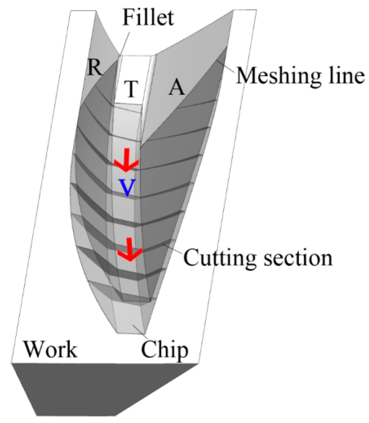
For ease of subsequent analysis, the cutting edges of the skiving tool are named A, T, and R, respectively.
Cutting edge A is the approaching edge of the cutting tooth that first cuts into the workpiece in the rotational direction of the tool, R is the recessing edge that is the last edge that separates from the workpiece, and T is the top edge.
The skiving cutting motion mainly includes three components: the workpiece rotates around its own axis with a velocity of
ωw, the tool rotates around its own axis with a velocity of
ωc, and the workpiece moves along its own axis with a feed velocity of
f. The relationship among
ωw,
ωc, and
f can be expressed as:
where
Zw and
Zc are the number of teeth of the workpiece and the tool, and
pz is the lead of the workpiece.
The cutting thickness of the tool is a crucial parameter affecting the cutting load, directly influencing tool wear. To study the variation law of cutting thickness during the gear skiving process, a simulation analysis of the undeformed chip geometry formation was conducted in UG.
The basic parameters of the skiving tool and gear workpiece are shown in
Table 1. The gear workpiece has an involute tooth profile. The cutting simulation results are illustrated in
Figure 2.
The skiving tool and workpiece rotate relative to each other based on the transmission ratio, creating relative sliding between the cutting tooth and the workpiece, and thereby forming the cutting motion.
For each cut of the skiving tool, there will be a swept surface formed inside the workpiece. As the workpiece moves axially, a series of swept surfaces are formed inside the workpiece; thus, the undeformed skiving chips can be bounded by two swept surfaces.
The tool cuts into the workpiece starting from the meshing line on one tooth flank of the workpiece, and thereafter, the cutting thickness gradually increases from 0 to the maximum and then exits the cut.
Figure 3 shows the cutting pattern obtained by the tool’s rake face during the cutting process with a sliding velocity
v of the tool relative to the workpiece. In the initial stage of cutting, the cutting area is divided into two segments. One is near the root of approaching edge A, and the other is near the node of the recessing edge R and top edge T. As the tool continues to cut, the cutting width increases, and the two segments of chips merge at the node of the approaching edge A and top edge T, forming a V-shape.
As the tool continues its cutting motion, the V-shaped chip thickness increases, and the top edge and recessing edge apparently contribute the most. Just before the tool exits the workpiece, the cutting thickness reaches its maximum, then drops to zero as the tool exits.
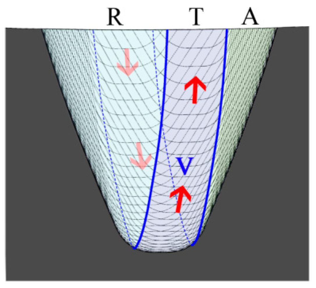
Figure 2 illustrates the cutting graph of the single feed gear skiving method, which comprises three regions: ‘R
’, ‘T
’, and ‘A
’. These regions are formed by the recessing edge
R, top edge
T, and approaching edge
A, respectively.
As shown in the figure, the majority of the material of the workpiece is removed by the recessing edge and the top edge of the tool, while the approaching edge only removes a small portion of the material. The different cutting loads assigned to the edges of the skiving tool may lead to uneven wear across the tool edges.
3. Analysis of Cutting Angles and Sliding Speed in Gear Skiving
The working angles and cutting speed of the skiving tool are crucial parameters affecting the cutting state andhave a significant impact on tool wear.
To study the variation laws of the working angles and cutting speed at different points along the cutting edges of the skiving tool during the skiving process, a calculation model for the working angles and cutting speed at a point O on the cutting edge was established.
Figure 4 shows the schematic diagram for the calculation of cutting angles and cutting speed in gear skiving.
Based on the algorithm from reference [
10], the normal vector
n of the cutting plane can be expressed as the cross product of the cutting edge vector
tc and the sliding velocity
v of the tool relative to the workpiece:
The unit vector
vn of normal cutting velocity at a point on the cutting edge can be expressed as:
In the orthogonal plane
P0, the normal working rake angle
γn at a point on the cutting edge can be expressed as the angle between the normal vector
n and rake face; it can also be expressed as the angle between the rake face normal vector
nr and the unit vector of normal cutting velocity
vn:
The normal vector of the flank face
nf at a point on the cutting edge can be expressed as the cross product of the cutting edge vector
tc and the helix vector of the flank face
tr:
In the orthogonal plane
P0, the normal working clearance angle at a point on the cutting edge
αn can be expressed as the angle between the normal vector of the flank face
nf and the normal vector of the cutting plane
n:
In the base plane
Ps, the tool inclination angle at point
O on the cutting edge
λs can be expressed as the angle between the cutting velocity
v and the normal cutting velocity
vn:
The tangential cutting velocity can be expressed as:
The intersection of the cutting edge and top edge is defined as the tool tip. If vt leans to the tool tip, vt is negative; otherwise, it is positive.
Based on the parameters in
Table 1, the working rake angle of the skiving tool during the skiving process was calculated. The results are shown in
Figure 5a. The horizontal axis represents the tooth thickness half-angle at a point on the cutting edge, the vertical axis represents the tool rotation angle, and the
z-axis represents the working rake angle of the tool.
The cutting edge of the tool starts cutting into the workpiece from the tooth meshing line until it exits the tooth space.
During the process, the working rake angle decreases from −1.2° to −47°. The corner portion connecting the top edge and the recessing edge has a high negative rake angle when exiting the cut. It is shown in deep red on the contour plot of the working rake angle. Generally, tools with negative rake angles are more prone to wear. Therefore, this part of the cutting edge is the most susceptible to wear in skiving tools, while the cutting conditions of the approaching edge are better than those of the recessing edge and top edge.
The calculation results of the working clearance angle during the skiving process are shown in
Figure 5b. Contrary to the working rake angle, the working clearance angle increases from 2° to 47° as the tool progresses through the cut. Generally, the working clearance angle is small when the cutting edge cuts into the workpiece and gradually increases as the tool exits the cut. The smaller clearance angle and thinner cutting depth at the cutting-in stage are difficult to form, which leads to wear on the tool flank.
The calculated results of cutting thickness during the skiving process are shown in
Figure 5c. The variation pattern of cutting thickness matches the simulation results. The cutting thickness starts at zero when the tool first engages the workpiece, gradually increases during the cut, and reaches its maximum when the tool exits the workpiece. The maximum thickness occurs at the edge connecting the top edge and the recessing edge.
In conclusion, single-pass skiving completes the entire tooth slot cutting, but the cutting conditions are poorest when the tool exits the slot, leading to tool wear. Therefore, adopting multiple radial feeds during the skiving process can effectively improve tool wear [
10].
The results of the calculation of the tool inclination angle during the gear skiving process are shown in
Figure 6a. As depicted in the figure, the inclination angle decreases from 9.4° to −49° during the cutting process. Generally, negative inclination angles are unfavorable for chip evacuation, thereby affecting the tool’s lifespan and processing quality. The figure indicates that the approaching edge has a significantly negative inclination angle when exiting the cut, whereas the top edge and recessing edge also have negative inclination angles but with smaller absolute values.
This suggests different chip evacuation rates for the approaching edge, top edge, and recessing edge, with chips prone to compress at the corner between the approaching edge and top edge, negatively impacting tool lifespan and workpiece quality.
The results of the calculation of the tangential cutting speed during the gear skiving process are shown in
Figure 6b. The variation pattern of tangential cutting speed
vt is similar to that of the inclination angle. The approaching edge has a high absolute tangential cutting speed when exiting the cut, whereas the top edge and recessing edge have lower absolute tangential cutting speeds, also indicating different chip evacuation rates. Since tangential cutting speed affects chip evacuation, chips are likely to compress at the corner between the approaching edge and top edge, negatively impacting tool lifespan and workpiece quality.
The results of the calculation of the normal cutting speed during the gear skiving process are shown in
Figure 5c. The normal cutting speed
vn increases from 453 mm/s at the beginning of cutting to 798 mm/s when exiting the cut, with a wide speed range, shown in
Figure 6c. Normal cutting speed is the primary speed component for chip formation, influenced by the tool and workpiece rotational speeds, axis intersection angle, and pitch circle radius.
4. Finite Element Analysis of the Gear Skiving Cutting Process
This study simulates the gear skiving cutting process through the use of the SPH method in LS-DYNA software. The SPH method is based on the Lagrangian formula, which discretizes continuous objects into movable particles that have the same physical properties as objects. The core is the interpolation algorithm, and the interaction between the particles is described by an interpolation function. Through the calculation of the interpolation function, the core estimation value of each particle can be obtained, and then the differential form is converted into the integral form by using the conservation law of continuum dynamics; thus the mechanical behavior of the whole system is obtained [
17]. The units used in this simulation are Kg, mm, ms, KN, and GPa.
The parameters of the skiving tool and internal gear are shown in
Table 1. Modeling the actual number of teeth for the simulation would require substantial computation time. Due to the periodic nature of the geometries of the skiving tool and the gear workpiece, this simulation uses a single-tooth structure for both the tool and the workpiece. The workpiece material is 45 steel, it is modeled using the Johnson–Cook material model with the parameters listed in
Table 2, and the friction coefficient is set to 0.2. The tool material is cemented carbide, and the elastic model is selected for the tool material in the simulation, with the parameters listed in
Table 3.
The SPH method differs significantly from traditional finite element simulation methods and offers advantages in many situations, especially in addressing large deformation problems of metal materials. Thus, the SPH method is increasingly used in the field of cutting processing. The chip formation process in gear skiving involves significant deformations, making it difficult to form chips using traditional mesh methods due to the large deformations in the workpiece material, which can lead to mesh failure.
Due to the periodic nature of the geometries of the skiving tool and the gear workpiece, only one tooth of the tool and one tooth slot of the workpiece are considered in this analysis to reduce computational load. The 3D models of the skiving tool and workpiece are imported into LS-PREPOST for meshing, which is an advanced pre-processing and post-processing program that is compatible with LS-DYNA. The tool uses a tetrahedral mesh with a mesh size of 0.1 mm. The workpiece uses an SPH mesh with a particle distance of 0.1 mm.
During the simulation of the gear skiving process, the freedoms of the workpiece tooth in
,
,
and its rotations around
are constrained, allowing rotation only around the
axis. Similarly, the freedoms of the tool tooth in
,
,
and its rotations around
,
are constrained, allowing rotation only around the
axis, as shown in
Figure 7. The rotational speeds of the tool and workpiece are set according to the transmission ratio to simulate the gear skiving process. The gear rotating speed is 500 rpm, and the feed rate per revolution is 1 mm.
5. Simulation Results Analysis
The stress states of the workpiece, chips, and tool at five different rotation positions during the gear skiving process, from tool entry to exit, are shown in
Figure 7.
Figure 8a: In the initial stage of cutting, the cutting zone is divided into two segments. The approaching edge cuts into the workpiece from the root, while the intersection of the recessing edge and the top edge also engages the workpiece.
Figure 8b: As the tool and workpiece rotate relative to each other, the cutting width gradually increases, and the two cutting zones merge at the intersection of the approaching edge and the top edge, forming a V-shaped chip.
Figure 8c,d: As the tool continues to rotate relative to the workpiece, the thickness of the V-shaped chip increases. Due to the large cutting thickness of the skiving cutter, the shear zone connecting the chip to the workpiece material experiences significant stress, with the maximum stress occurring at the intersection of the approaching edge and the top edge. The chip is prone to fracture in this region.
Figure 8e: As the tool continues to rotate relative to the workpiece, the chip gradually separates from the workpiece material. The stress at the intersection of the approaching edge and the top edge decreases, indicating the formation of cracks in the chip in this region. Actual cutting processes also show that the chip is prone to fracture in this region [
13], leading to fluctuations in cutting force and affecting the quality of the machined tooth surface.
Figure 8e–j show the stress states at the five different rotation positions in the process from the tool entry to exit. During this process, the cutting stress on the cutting edge near the tool tip is the highest, indicating that the tool tip is the most susceptible to wear.
The simulation results indicate that the maximum values of the equivalent stress of the tool are higher compared to the normal value. There are several possible reasons for this phenomenon:
Due to the issue of simulation computation, the particle distance between SPH balls cannot be too small, which is selected as 0.1 mm, and it has sufficient calculation accuracy. Therefore, in order to better reveal the deformation law of skiving chips, the feed rate per revolution of the workpiece is increased to 1 mm, which is very large compared with the 0.2 mm in reality.
Actually, the tool edge radius is about 5 microns, but in simulation, the blade is sharp, which may result in the concentration of stress.
In the practice of gear skiving, the radial feed of the cutting tool is divided into multiple times, while in simulation, only one radial feed is implemented, so the material removal rate is very large.
The rake angle of the skiving tool is zero, which is another reason for the high cutting stress.
Figure 9 illustrates the contour plot of equivalent stress extracted from the cutting edge during the tool entry to exit process. As shown in the figure, the stress on the cutting edge near the tool tip peaks at a rotation angle of 25°. At this rotation position, the cutting thickness is not the best, and the cutting conditions are not the worst, but due to the longer length of the cutting edge involved in the cutting, the cutting load is high, leading to high stress values on the cutting edge. Subsequently, as the cutting edge exits the cut, the stress values gradually decrease.
Figure 10 shows the maximum equivalent stress
at the points on the cutting edge during the tool entry to exit process. The maximum equivalent stress
can be expressed as:
where
is the equivalent stress extracted from the cutting edge during the tool entry to exit process.
As depicted in
Figure 10, the maximum cutting stress is highest at the positions of the two red lines, primarily due to the absence of a fillet at the tool tip, leading to the concentration of stress. Therefore, in the tool design stage, selecting an appropriate fillet radius for the tool tip is essential to prevent premature tool wear. Compared to the average cutting stress on the approaching edge, the average cutting stress on the recessing edge is higher, indicating that the cutting conditions for the approaching edge are better, while the cutting conditions for the recessing edge and top edge are poorer, making them more prone to wear.
This phenomenon is also observed in practice. During the use of the skiving tool, the top edge and recessing edge are the first to show signs of wear. In
Figure 11, the wear and chips of the skiving tool are shown. The tool tip shows signs of wear, with the intersection of the recessing edge and top edge exhibiting the most significant wear. The chips formed by the recessing edge and top edge are thicker and wider, while the chips formed by the approaching edge are thinner and narrower. This indicates that the recessing edge and top edge handle the larger portion of the cutting task. Increasing the feed per revolution of the workpiece results in thicker chips, and the chip formation at the intersection of the approaching edge and top edge is prone to fracture, leading to fluctuations in cutting force and affecting the quality of the machined tooth surface. Therefore, the feed per revolution of the workpiece should be optimized.
6. Conclusions
Through simulation methods, the variation patterns of cutting thickness, tool working angles, cutting speed, and cutting stress during the gear skiving process were analyzed, revealing the characteristics of the skiving cutting process.
Kinematic Simulation Analysis: The kinematic simulation analysis of gear skiving revealed the variation pattern of the cutting thickness along the tool edges and the skiving cutting profile. It was found that the recessing edge and top edge remove a larger amount of material, leading to uneven wear on the skiving tool edges.
Numerical Simulation Calculations: The numerical simulation method of the gear skiving process was provided, which can be used in the cutting parameter optimization of gear skiving. The numerical simulation calculations indicate that the cutting conditions and chip evacuation state are poorest when the skiving tool exits the gear slot, making the tool more prone to wear and affecting the quality of the workpiece.
Finite Element Simulation Analysis: A new method of the FEA simulation of gear skiving was provided, and the chip formation mechanism in gear skiving was investigated. The finite element simulation analysis shows that the maximum cutting stress occurs at the chip convergence area at the intersection of the approaching edge and top edge. Fractures of chips are prone to being formed in this region, causing fluctuations of cutting force, which negatively impacts tool life and the quality of the tooth surface.


