1. Introduction
The main overall goal of structural control is to reduce fatigue so that large structures, such as wind turbines (WTs), have longer service lives and require less maintenance. In particular, tuned mass dampers (TMDs) are a widely used structural control system in several disciplines, highlighting its extensive use in civil engineering applications. TMDs have been implemented in a variety of configurations on both onshore and offshore wind turbines, demonstrating their effectiveness in reducing vibrations caused by internal (e.g., pitch control of the blades) and external disturbances (e.g., wind, waves) [
1,
2].
Tuned mass dampers (TMDs) are structural control devices consisting of springs, dampers, and masses that move longitudinally and/or laterally, exerting forces to reduce structural vibrations. TMDs are commonly classified as passive, semi-active, or active, depending on whether their parameters are fixed, varied according to a predefined schedule, or adaptively adjusted.
The parameters of passive TMDs remain constant. Semi-active TMDs are essentially adjustable passive TMDs that automatically re-tune their parameters through adjustment mechanisms, staying optimally tuned to their target frequencies. Due to this continuous in situ re-tuning (via adjustments in stiffness and/or damping), semi-active TMDs exhibit robust performance even when the dynamics (and thus the natural frequencies) of the target structures change.
An active tuned mass damper (ATMD) integrates a controllable element, such as a linear actuator, into a passive TMD. Structural vibrations are continuously monitored to generate damping forces that reduce the vibrations. ATMDs require external power, but since an active TMD is essentially a passive TMD with an added actuator, part of the vibration suppression is accomplished by the passive component, minimizing the power demand. In an active TMD, parameter adaptation occurs continuously, while in a semi-active TMD, the parameter adjustments follow a gain scheduling scheme.
Despite their apparent simplicity, TMDs have proven to be highly effective in reducing wind-induced oscillations in civil structures such as bridges, tall buildings, and wind turbines [
3]. Common passive control devices researched for wind energy converters include tuned mass dampers (TMDs), ball vibration absorbers (BVAs), tuned liquid dampers (TLDs), rolling ball dampers (RBDs), tuned inerters, and tuned liquid column dampers (TLCDs).
TMD parameter tuning is a crucial task, as is the case in any control system. Several different techniques can be used to adjust these parameters, specifically spring stiffness and damping values. Typically, these parameters are fixed (passive TMDs), but it may be advantageous to adjust them based on internal variables or external disturbances (semi-active or active TMDs), where stiffness and/or damping can be modified during operation [
4].
The main advantage of semi-active control over passive control is its adaptability to external changes and disturbances. Passive TMDs are tuned to the natural frequencies of the structure under specific environmental conditions. For instance, in the case of a floating offshore wind turbine, the optimized TMD settings differ between scenarios with significant wave heights or calm seas. On the other hand, semi-active control enables the TMD parameters to adapt to both situations.
The most commonly used techniques for tuning TMD parameters include frequency tuning, surface plots, and metaheuristic methods such as genetic algorithms (GAs). Among these, the surface plot approach is often disregarded due to its computational cost and time requirements. Frequency adjustment is efficient for certain applications, but its limitations have led to the widespread adoption of evolutionary optimization techniques like GA [
3].
In this paper, the authors propose and compare passive and semi-active structural control methodologies for an NREL 5 MW floating offshore wind turbine (FOWT) [
5]. This barge-type floating device is mounted on an ITI platform. A benchmark simulation model is developed in Matlab/Simulink for control design purposes [
6], and it is validated against the OpenFAST v3.5.4 non-linear model. OpenFAST software is recognized in the research community for its high-fidelity simulation of wind turbines.
First, a passive TMD is installed in the WT nacelle to reduce vibrations, typically measured as the top tower displacement (TTD) [
7]. The effectiveness achieved in damping the vibrations’ amplitude depends on the tuning of the TMD parameters, making this task challenging [
8]. Therefore, alternative heuristic methods, including evolutionary algorithms like GA, have been explored [
9,
10]. For the case of the 5 MW FOWT here presented, the authors compare the cases where a reference TMD as described in [
11] is used, the case of a wind turbine without a TMD, and finally, the case of a wind turbine containing a passive TMD for which the parameters are tuned by GA in terms of vibration reduction, highlighting the improvements provided by the optimized structural control.
It is important to note that the objective of this work is not the design of a specific TMD but rather to evaluate different methodologies for optimizing the generation of appropriate control signals for adaptive TMDs. The proposed methodologies can be applied to any adaptive TMD available in the existing literature.
Next, a semi-active TMD control is designed, where the spring stiffness and damping parameters can be adapted in real time according to the turbine’s operating conditions. Two cases are considered for the semi-active structural device: (i) control actions based on the amplitude of tower oscillations (TTD) and (ii) parameter optimization according to the input frequency. During simulations, these parameters are computed online using a gain scheduling approach to reduce tower oscillations.
The simulation results obtained demonstrate that the semi-active structural control improves the dynamic response of the system and mitigates tower vibrations compared to the cases of passive control or no control at all. As far as the authors know, the few existing studies on semi-active structural control for floating wind turbines do not use the two variables considered in the gain scheduling control approach here explored. Additionally, the real-time identification of input frequency enhances the control’s ability to handle dynamic changes caused by wave disturbances.
The rest of the paper is organized as follows:
Section 2 discusses related works on structural control for wind turbines.
Section 3 validates the simplified model used in this study, incorporating periodic external forces to simulate wave impacts on the FOWT barge.
Section 4 presents the metaheuristic optimization of the passive TMD’s spring stiffness and damping coefficients. Two semi-active control strategies based on (i) tower oscillation amplitude and (ii) input frequency are introduced in
Section 5, followed by the analysis of the results. Finally,
Section 6 concludes the paper with a summary of findings and suggestions for future work.
2. Related Works
Tuned Mass Dampers (TMDs) have proven highly effective across various applications, particularly in the construction of buildings and bridges. In recent decades, they have also been utilized to mitigate wind turbine vibrations. Typically, TMDs are mounted in the nacelle of bottom-fixed turbines, both offshore and onshore. In contrast, modern floating offshore wind turbines (FOWTs) have experimented with various designs, employing single and multiple TMDs installed in the tower, platform, or nacelle. Most designs use passive TMDs, which, when properly tuned, significantly reduce vibrations’ amplitudes.
There exist several published examples of passive TMDs applied to FOWTs. For example, the study in [
3] compares tuned TMDs for a 5 MW barge-type NREL FOWT, where the spring and damper parameters are optimized using genetic algorithms (GAs) and the natural frequency. Optimizing the TMD parameters with GA improves the vibration suppression rate, using the standard deviation of the tower top displacement (TTD) as the cost function. In [
8], passive TMDs installed on the platform and in the nacelle of a semi-submersible FOWT are optimized using GA across three different configurations, aiming to reduce TTD.
Wang et al. [
12] developed a reduced dynamic model of a Multi-TMD (MTMD) equipped FOWT platform, considering tower bending and barge degrees of freedom. Using GA, they optimized three TMD configurations: one in the nacelle, one on the platform, and the proposed MTMD. The results showed that the MTMD design outperformed the others in reducing vibrations from external loads.
Villoslada et al. [
13] analyzed the performance of a 5 MW barge-type FOWT using a TMD optimized with GA. This study included stops to limit the TMD stroke, which were incorporated into the design of a passive structural controller installed in the nacelle. The optimized FOWT showed reduced collective pitch-tower bending mode vibrations.
In [
14], a TMD was designed and used for a 5 MW NREL monopile FOWT. In this case, GA and the interval approach were used to tune the passive dampers, demonstrating improved vibration attenuation, as indicated by a reduction in the mean square of rotor acceleration and displacement.
An alternative approach was presented in [
9], where the TMD damping and stiffness parameters are modeled as static controllers, with gains adjusted according to specific FOWT performance requirements. These criteria are formulated using a convex optimization program and solved with an iterative Linear Matrix Inequality (LMI) process. In this case, the TMD was installed in the nacelle.
Although semi-active and active controllers are less commonly used, ref. [
15] explores their application. Research on semi-active controls is limited, especially in wind energy [
4]. However, as shown in [
16], a semi-active TMD can perform comparably to an H∞-based active TMD control, surpassing the passive TMD approach. The study used a model-free adaptive control strategy with a quadratic programming module, adjusting the damping coefficient and spring stiffness of the semi-active TMD in real time. The semi-active TMD was mounted facing upwind, reducing vibrations by minimizing stress on the floating platform’s pitch angle. Sarkar and Chakraborty [
17] proposed several semi-active magnetorheological liquid column dampers (MR-TLCDs), designed to maximize energy dissipation and reduce vibrations. The multi-blade coordinate transformation employed in the structural control design converted system matrices into a non-rotating frame, followed by temporal averaging for the application of linear control rules.
In Park’s Ph.D. dissertation [
4], a semi-active control for a tower TMD is developed using ground hook (GH) control. This sub-optimal control strategy is straightforward to implement, as it relies on structural feedback. The TMD damper operates similarly to magnetorheological (MR) dampers. In [
18], an MR damper modeled using the Bouc–Wen approach is adjusted for an offshore wind turbine. Various semi-active controllers based on the GH strategy are applied to fixed-bottom and floating wind turbines, with tests conducted on monopile and tension leg platform (TLP) constructions. The effects of TMDs at the tower top are evaluated, comparing passive and semi-active operations with on–off state damping control.
Leng et al. [
19] used a semi-active TMD based on a three-dimensional magnetorheological elastomer (MRE) to control bidirectional vibrations of a bottom-fixed monopile turbine under wind, seismic, and wave loads. The TMD installed in the nacelle dynamically adjusted its stiffness by tracking the dominant frequency of the turbine in real time.
In [
20], a magnetorheological (MR) damper is presented in a semi-active TMD configuration for a FOWT. The damping force is adjusted by varying the voltage applied to the MR damper. A retrogression controller is developed, incorporating an adaptive control force that reduces the control requirements and generates an implementable semi-active control signal.
Dinh et al. [
21] used a short-time Fourier transform to identify real-time frequencies of a floating wind turbine, subsequently modifying the TMD spring stiffness. Although this approach could initially seem similar to the method proposed here, it differs, as their study implemented TMDs on each rotor blade, the nacelle, and the foundation of a spar FOWT.
As discussed above, most semi-active structural control systems utilize MR technology. In this work, a gain scheduling control architecture is used for a barge-type FOWT, and the authors propose a novel approach where the TMD coefficients are adapted based on two measurements not yet considered: the amplitude of oscillations and the identified input frequency.
3. Wind Turbine Model Validation and Disturbances
To investigate FOWT dynamics and implement new structural control elements, the work begins with the use of a simulation model that captures the system’s behavior and allows for easy modifications and efficient simulations. OpenFAST, a high-fidelity software tool, provides reliable results but requires substantial computational resources and programming effort for model modifications. Therefore, this study utilizes a simplified FOWT model, validated against realistic non-linear OpenFAST simulations.
The model under study has three degrees of freedom (DoF), allowing pitch motion in the tower plane (fore–aft direction). The masses represent the turbine tower, platform, and TMD mounted in the nacelle. It has been shown that the dynamics of the blades and other components have minimal impact compared to the effects of the three primary DoF considered, thus the blades and mooring lines have not been included. The main objective of this work is to reduce vibrations and stress in the main structure. Initially, the model does not account for external wind or wave forces, focusing instead on demonstrating the effectiveness of the semi-active control in reducing tower displacement through adaptive TMD parameter tuning.
A floating barge-type wind turbine is selected for a more challenging case. While vibration reduction is a common issue for all wind turbines, it is particularly critical for offshore wind energy converters. In this case, the FOWT considered has a horizontal axis with a 5 MW nominal power output, three blades measuring 63 m in length, and a hub height of 90 m. The floating platform measures 40 × 40 × 10 m and is anchored to the seabed with eight mooring lines [
5].
3.1. Simplified Model
The dynamic model of the floating turbine system is derived using the Euler–Lagrange approach, following the method outlined by He et al. [
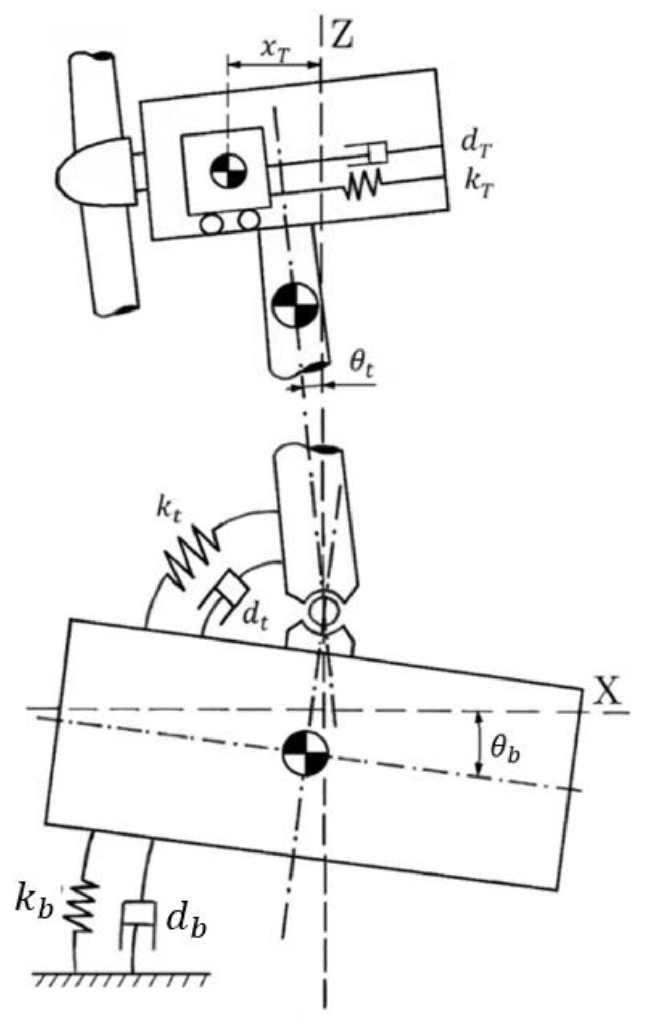
22]. The simplified model is obtained by applying a small-angle approximation, resulting in a linear model consisting of three linear differential equations. Each state variable represents the dynamics of a specific element of the system: TMD, tower, and barge. The TMD is installed in the nacelle (
Figure 1).
The system of linearized equations that describe the model are as follows:
The platform, tower, and tuned mass damper (TMD) are denoted by the subscripts
,
, and
, respectively. The TMD has a single degree of freedom (DoF), corresponding to the translational motion of its mass,
, while the platform and tower each have a single rotational DoF. In this model, the hydrostatic restoring forces and water friction are represented by a torsional spring and a damper attached to the barge, as shown in
Figure 1. Additionally, a rotational spring and damper are included to represent the stiffness and damping characteristics of the tower. In the equations,
denotes the rotational or linear damping constants,
represents rotational or linear stiffness, and
indicates the rotational inertia. The
terms refer to various distances:
is the distance from the tower’s pivot point to its center of mass,
is the distance from the platform’s center of mass to the pivot point, and
is the distance from the TMD’s center of mass to the pivot point.
The platform pitch angle, , is defined as the angle between the vertical z-axis and the vertical axis of the platform, while is the angle between the vertical z-axis and the tower. The variable represents the distance travelled by the TMD mass along the x-axis measured from the vertical z-axis. The state variables in this model are , and with their derivatives , , and .
3.2. Model Identification and Validation
The state-space representation of the system can be derived from the equations of the theoretical model, Equations (4)–(6). Initially, the model identification is performed without including the TMD dynamics. Therefore, the state-space model consists of four first-order differential equations with constant coefficient matrices
A,
B,
C,
D, Equations (7) and (8). The output
is a vector that contains the barge and tower angular displacements,
and
. During the model identification process, the inputs are considered to be zero, i.e.,
B =
D = 0. A free decay test is performed; for this, the barge is initially displaced from its equilibrium (that is, the initial condition for the barge pitch angle is set to be different from zero). In this case, it is seen that both platform and tower exhibit unforced damped oscillations (decaying amplitude).
By simulating the turbine under similar operating conditions and the same inputs, OpenFAST helped to determine the spring stiffness, damping coefficient and inertia value of the model. This simulation program allows the generation of a wide variety of data sets needed for model identification and validation. In this study, the Levenberg–Marquardt algorithm was employed for parameter identification, using various initial platform angular displacement angles. These free decay experiments are also representative of wave-induced responses. The parameters obtained from the identification procedure are presented in
Table 1, where subscripts
and
correspond to the barge and tower, respectively. The remaining parameters are predefined and can be found in [
23].
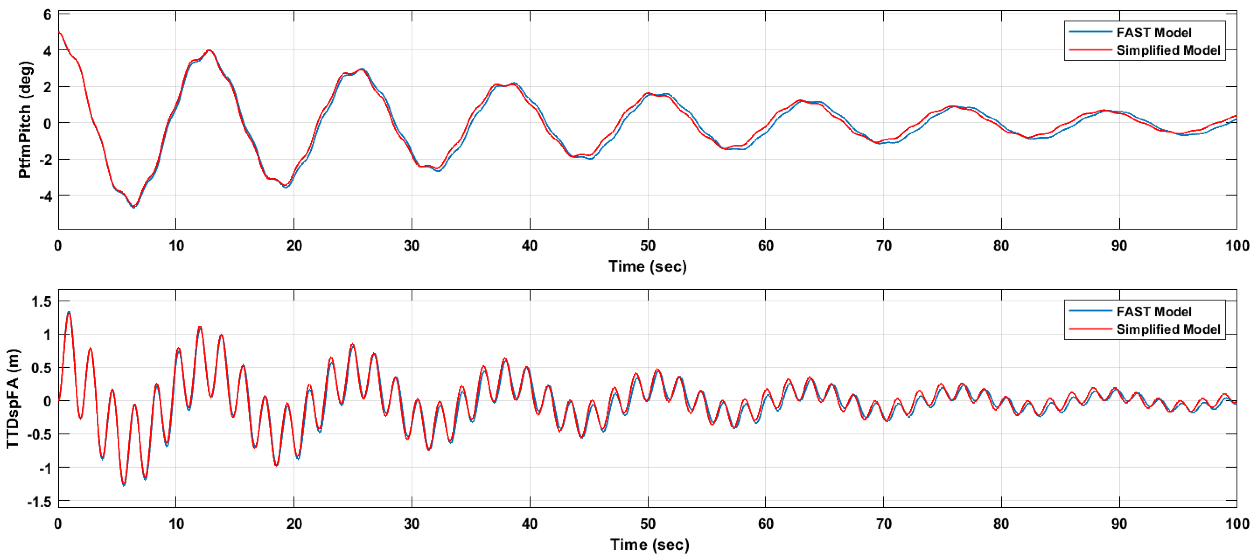
The response of the simplified model is validated by comparing it with an OpenFAST FOWT simulation for a 100 s test run. In this comparison, the initial pitch angle of the platform is set to either 3° or 5°, including the influence of the tuned mass damper (TMD). The TMD parameters are defined as follows: mass
= 20,000 kg, damping coefficient
= 9000 Ns/m, and stiffness coefficient
= 5000 N/m. This configuration is implemented to ensure the accuracy and validation of the theoretical model. It is worth noting at this point that the TMD setup utilized aligns with the configuration described in [
11].
The results of both simulations are presented in
Figure 2. The comparison between the OpenFAST reference model (blue line) and the reduced model simulation (red line) shows a satisfactory agreement, with a minor discrepancy that gradually increases over time. The pitch angle of the platform, referred to as PtfmPitch in OpenFAST, is depicted in the first plot. In the simplified model, this corresponds to the pitch angle
, which is the angle between the platform and the vertical
z-axis.
The second plot illustrates the horizontal displacement of the tower top relative to the z-axis, represented by the Tower Top Displacement (TTD) in the Fore–Aft direction (TTDspFA). In the proposed model, this variable is expressed as , where denotes the length of the tower. Analyzing the behavior of these signals is important, as the oscillations induce loads on the tower, thereby reducing the wind turbine’s operational lifespan. The average absolute error of the tower deflection (TTDspFA) is 0.042, which can be considered an acceptable value for validation purposes.
3.3. Addition of External Periodic Disturbances
The simplified model presented in the previous subsection is specifically designed for conducting free decay tests. This process involved initializing the system with conditions that deviate from the platform’s equilibrium state, while ensuring the absence of external disturbances. Such an approach facilitates the analysis of the system’s inherent dynamics and control design without introducing additional complexities. Moreover, it enables the determination of the natural frequency, which is dictated by the mass and stiffness characteristics of the wind turbine.
In the context of designing semi-active control strategies, it is important to adjust the turbine dynamics to generate oscillations at different frequencies. This method enables the assessment of the system’s behavior not only during free decay but also when subjected to simulated external forces. To implement this, a vertical force is exerted at one end of the platform, replicating the impact of wave motion. The applied force follows a sinusoidal pattern, with its amplitude (A) and frequency (
) being customizable.
As a result of applying the external force at the edge of the barge, a moment is induced:
Applying small angle approximations, this becomes
The expression in (11) can now be incorporated into the platform’s angular acceleration Equation (1) to account for the torque generated by the external force, yielding the revised form of Equation (12). Equations (2) and (3) of the simplified model remain unaltered.
In linear systems theory, it is well known that a periodic input force applied to a linear system induces a steady-state response with an oscillation frequency that matches the frequency of the applied force. This fundamental property of linear systems forms the basis for the development of a frequency-dependent adaptive control strategy, which will be detailed in the following sections.
4. Passive TMD Control Tuned by Genetic Algorithms
In this section, the TMD device damping coefficient
and spring stiffness
are optimized using a metaheuristic method, Genetic Algorithm (GA). To enable a comparison between the results presented here and those reported in other studies, the TMD mass has been set to 20,000 kg, consistent with [
11], as it aligns with the TMD described in that publication.
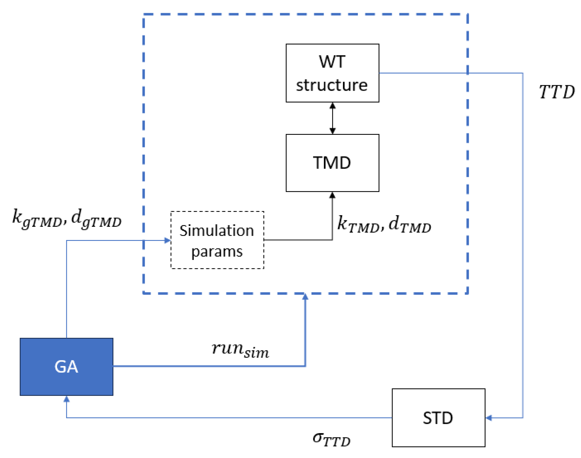
The GA generates the initial tuning parameters for the passive TMD. These are the stiffness
. These coefficients are stored in the simulation as
. Subsequently, the simulation is executed (
). Upon completion, the tower top displacement (TTD) is analyzed, focusing on the standard deviation of this signal,
, which acts as the fitness function for the GA. This process is repeated iteratively until the optimization convergence criterion is satisfied (
Figure 3).
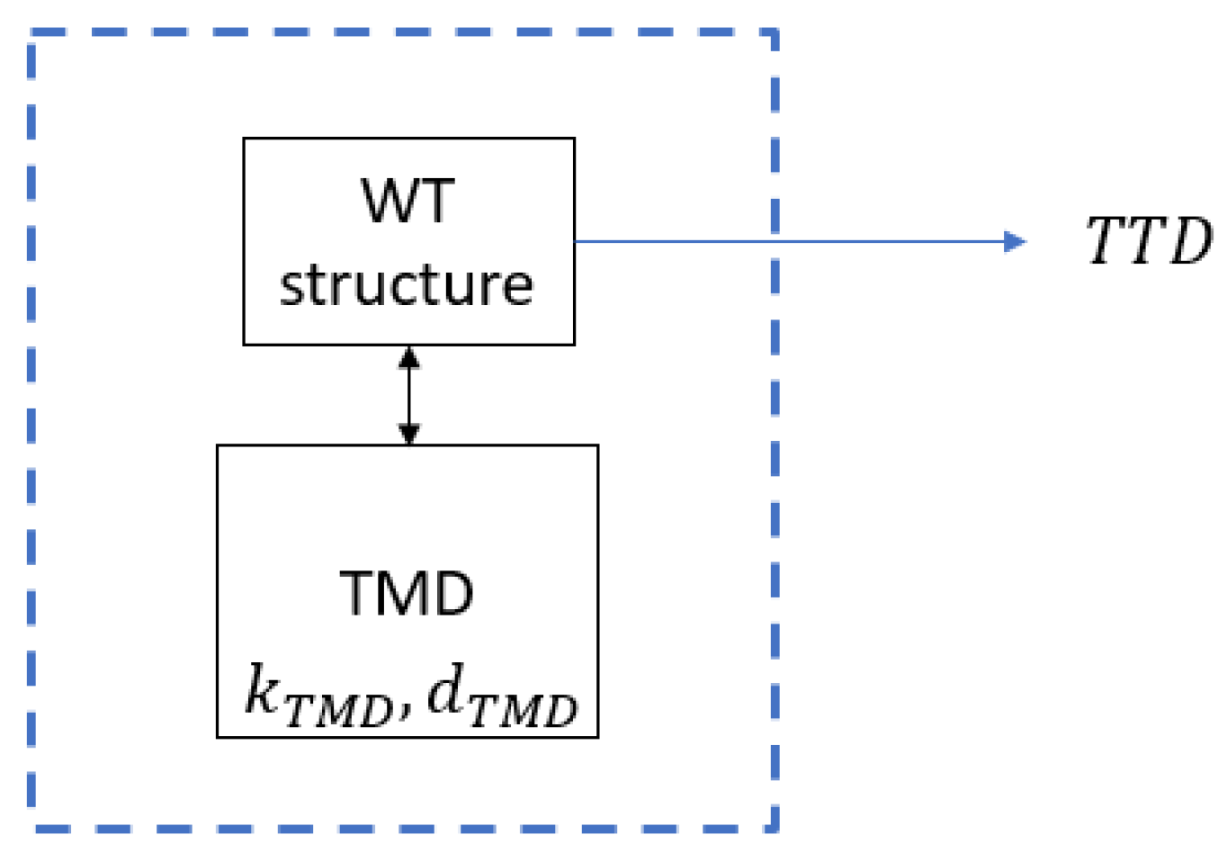
Figure 4 shows the execution scheme of the passive TMD after the optimization process is complete. It can be observed that the TMD parameters cannot be externally adjusted.
In the optimization process, an initial population of 75 individuals is used for the GA. Each individual comprises two variables to be optimized (chromosomes): the spring constant
and damping coefficient
. Genetic operators, crossover and mutation, are applied with probabilities of 0.05 * Population and 0.01, respectively. The stop criterion is triggered when the average change in the cost function remains below the value 10
−6 for at least 15 consecutive generations. The complete GA configuration is detailed in
Table 2. The fitness function is defined as the standard deviation of the fore–aft tower top displacement (TTD), denoted as σ
TTD-FA.
The values obtained with this optimization are spring stiffness = 4868 N/m and damping coefficient = 2419 Ns/m, respectively.
5. Semi-Active Structural Control
It is well known that semi-active control strategies can be approached by both active and passive control techniques. Instead of directly applying a force to the structure, as in the case of active control strategies, the control actuator in a semi-active approach modifies the parameters of a passive energy device—in this case, a TMD—whose parameters are adjusted based on specific performance criteria. This semi-active control strategy is simpler than an intelligent or active control approach, as it allows for easier optimization of the damper in situ [
24,
25]. It enhances the performance of passive TMDs, which have fixed coefficients.
In this study, the TMD parameters are defined as functions of the vibration amplitude and input frequency. Consequently, two semi-active control approaches are proposed:
5.1. Semi-Active Controller Based on the Amplitude of Tower Vibrations
A semi-active control strategy based on a Tuned Mass Damper (TMD) is proposed. The parameters of the TMD—spring stiffness and damping coefficient —were optimized using the Transfer Time Domain (TTD) method. During the simulation, these parameters are adaptively adjusted based on the standard deviation of the TTD using a gain scheduling approach.
To design the gain scheduling strategy, the amplitude of oscillations at the top of the tower, as depicted in
Figure 5, was analyzed. The initial oscillation amplitude exceeded 1 m, gradually decreasing throughout the simulation, reaching values as low as 0.2 m (
Figure 5, blue line, without TMD). As a result, the TMD parameters were adjusted through an optimization process that considers this range of amplitudes. The system response is segmented into three distinct phases, based on the standard deviation of the tower top displacement:
Section 1:
Section 2:
Section 3:
It is important to note that the optimization was performed independently for each segment, under the assumption that the selection of optimal parameters for one segment does not affect the optimization process for the other segments. Consequently, three separate optimization processes were conducted.
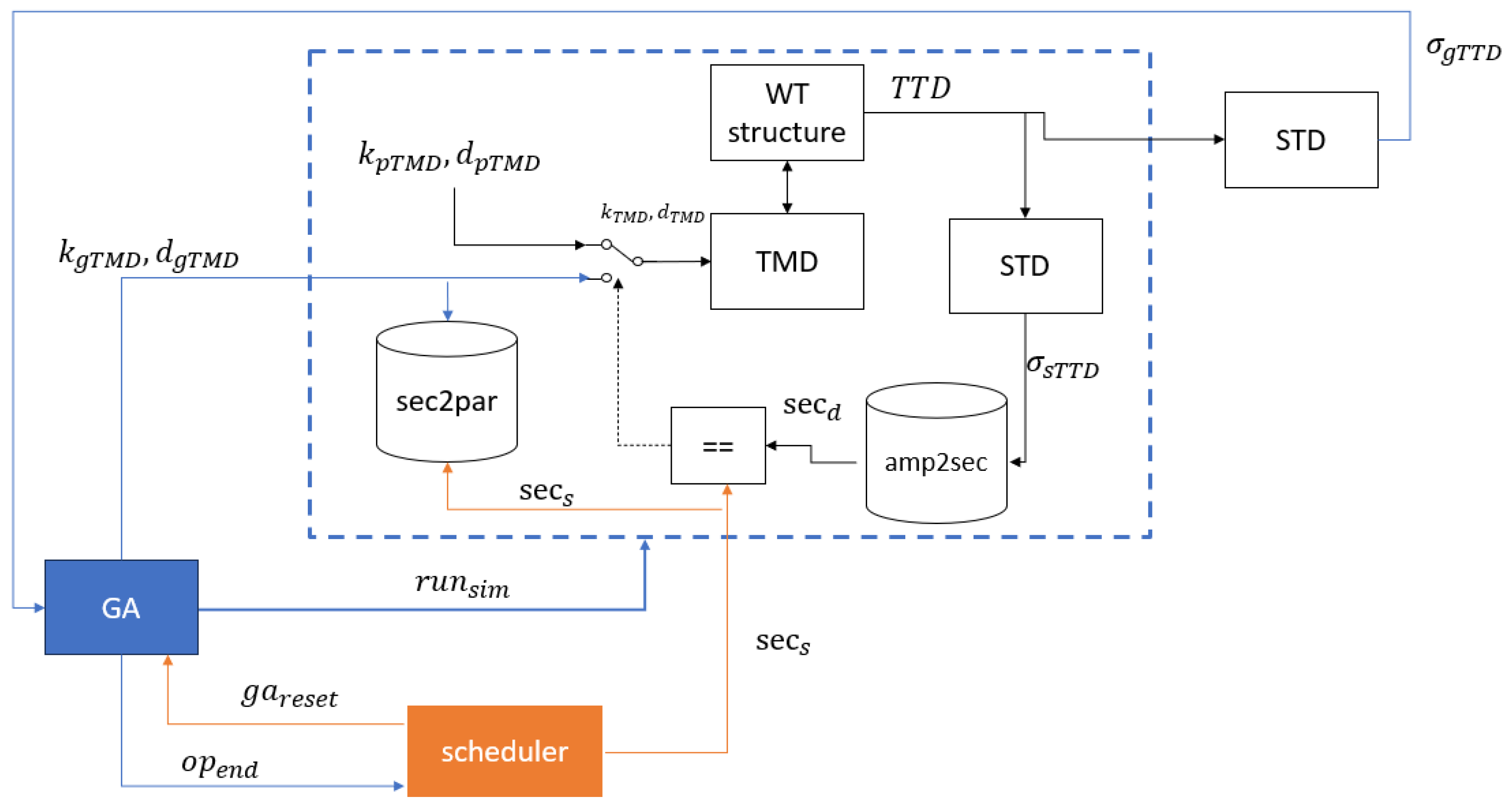
Figure 5 illustrates the optimization scheme for the amplitude-based semi-active TMD. The color of the arrows indicates the type of signal and its source. Signals shown in black are generated during each iteration of the simulation. Signals depicted in blue are produced by the Genetic Algorithm (GA) at the start or end of each simulation. Finally, signals in orange are generated by the scheduler upon completion of the GA optimization process, triggered by the condition
.
The scheduler initializes with
, indicating the amplitude section to be optimized. The scheduler (represented by the orange block in
Figure 6) resets the Genetic Algorithm (GA) with
, and subsequently begins the optimization process. The GA then generates the tuning parameters
.
The Genetic Algorithm (GA) initiates the simulation with the signal
. During the simulation, the standard deviation of the TTD,
, is analyzed at each simulation control period. This variable is used to determine the amplitude section of the signal,
. If the current amplitude section
matches the section set by the scheduler,
(i.e.,
, the switch for the TMD input changes its state, and the TMD input signals
are updated with the new parameters provided by the GA
, corresponding to the second position of the switch in
Figure 5. If the sections do not match, the input signals default to the optimal parameters obtained for the passive TMD
represented by the first position of the switch.
Upon completion of the simulation, the standard deviation of the TTD for the entire simulation, is calculated. This value serves as the fitness function for the GA. If the fitness value is better than the best recorded fitness value up to that point, the new parameters are stored in the lookup table sec2par (row indicated as ). establishing the relationship between the amplitude section and the TMD gains, i.e., .
The GA optimization process is executed iteratively until the termination criterion is satisfied, indicated by the signal . At this point, the scheduler advances to the next amplitude section for optimization, updating the section indicator to . The process concludes once the optimization has been completed for all defined amplitude sections.
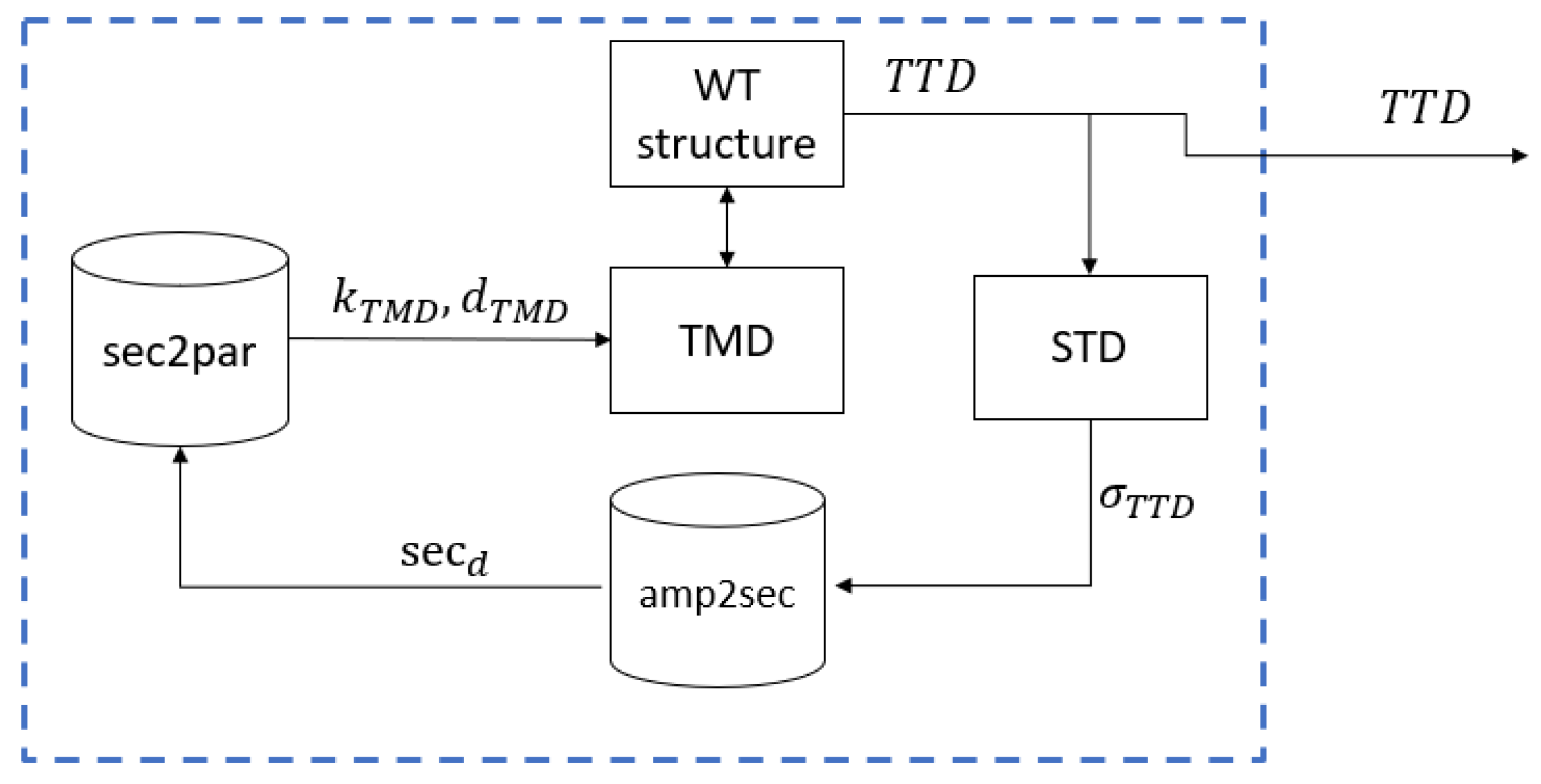
Once the optimization process is finished, the TMD can be implemented according to the scheme presented in
Figure 6.
During each control period, the standard deviation of the TTD is calculated and used to identify the current amplitude section using the lookup table “amp2sec”. This value serves as the index in the lookup table “sec2par” to retrieve the corresponding values of the pair , which are then used as the input signals for the TMD.
For the experiments, the same TMD mass and simulation settings as those used in the passive TMD cases were applied, including an initial platform pitch of 5° (free decay) and a simulation time of 100 s. The configuration of the Genetic Algorithm (GA) remains unchanged from the previous section, except that in this case, the range of the initial population is extended to [500, 500; 20,000, 20,000] in order to prevent early convergence on a local minimum.
The optimal values of
and
obtained for each section are presented in
Table 3 below:
Table 3 shows that the optimal values obtained for the lower amplitude oscillations (
Section 1 and
Section 2) are relatively similar, but they differ significantly from the values obtained for the higher amplitude oscillations (
Section 3). Furthermore, the optimal parameters found for
Section 3 are comparable to those determined during the optimization of the passive TMD (refer to
Section 4). This outcome was anticipated, as the primary focus of the optimization is to reduce larger amplitude oscillations.
Based on these findings, it was decided to further subdivide
Section 3 into two equal segments, as follows:
Section 3.1:
The results obtained in this case are as indicated in
Table 4:
5.2. Semi-Active Controller Based on the Frequency of the Vibrations
It is standard practice to tune TMDs to a specific vibration mode, typically the first mode, as it often induces the largest amplitude response. Adaptive control, however, offers the capability to tune a TMD at multiple frequencies. To achieve this, the TMD must be configured with optimal parameters to mitigate the system response across various vibration modes. In order to explore this approach, a frequency-domain analysis of the system response is necessary. The simplified model as described in
Section 3 provides the theoretical framework. It includes an external force that simulates wave effects, allowing for variations in the tower’s oscillations. The external force applied is a sinusoidal signal with a magnitude of 90,000 kN, featuring frequencies aligned with the inherent frequencies of the system, as detailed in the subsequent lines.
To evaluate the FOWT response in the frequency domain and identify the vibration modes, the power spectral density (PSD) must be determined. By analyzing the PSD, the frequencies at which power peaks occur can be identified, revealing the system’s dominant vibration modes. This estimation process involves calculating the Fourier transform of the signal’s autocorrelation function, which, in this case, corresponds to the movement of the wind turbine tower top.
For non-periodic signals, it is common to assume periodicity over specified time intervals. The Fourier transform is then computed for these intervals, yielding the discrete Fourier spectrum of the signal, represented by the Discrete Fourier Transform (DFT). The DFT is defined as follows:
where
is one of “
n” roots of unity and the autocorrelation function is the correlation of the signal with a delayed copy of itself as a function of delay.
Based on this analysis, two power peaks were identified: one at 0.08 Hz and another at 0.54 Hz, corresponding to the first and second vibration modes of the tower–platform system, respectively. These results are consistent with those reported in reference studies such as [
11].
The passive TMD used for structural control was tuned based on a free decay test, which matched the first natural mode at 0.08 Hz. In this case, the optimal values obtained for the TMD spring stiffness and damping coefficient were 4868 N/m and 2419 Ns/m, respectively. While this optimized passive TMD effectively reduced the system response at the specific frequency of 0.08 Hz, it did not mitigate the response at the second mode frequency. The proposed semi-active control strategy addresses this limitation by dynamically adapting the TMD to the prevailing frequency, which may be influenced by wave-induced forces at a different frequency. The current frequency is identified through the Fast Fourier Transform (FFT).
The scheme for optimizing the frequency-based semi-active TMD is presented in
Figure 7, using the same color code as in
Figure 5. In this configuration, the scheduler generates a set of frequency wave scenarios, and the wind turbine (WT) structure is tested under wave excitation at these primary frequencies.
The scheduler begins by assigning a value for the wave frequency, . It then resets the Genetic Algorithm (GA) and initiates the optimization process. The GA generates a pair of tuning parameters for the TMD , which are applied as inputs to the TMD. After the simulation completes, the standard deviation of the TTD is calculated and used as the fitness function for the GA. If the calculated fitness value is better than the best value recorded up to that point, the new parameters are stored in the lookup table corresponding to the current wave frequency, .
This process is repeated iteratively until the stop condition of the GA is met, signaled by . At this point, the scheduler resets the GA and assigns a new wave frequency, . The procedure continues until all frequencies in the predefined frequency list have been tested.
In this study, the TMD parameters were optimized using the GA for the second natural frequency, corresponding to excitation of the turbine by an external force at 0.54 Hz. The configuration of the GA was consistent with that described previously. The optimized values for the TMD spring stiffness and damping coefficient were determined to be 29.950 N/m and 29.530 Ns/m, respectively.
It is important to highlight that these values for the damping coefficient and spring stiffness are relatively high. This can be attributed to the fact that the tower is excited by a force at 0.54 Hz, meaning it tends to oscillate in a rapid manner—approximately every two seconds. As the TMD mass aims to oscillate at the same frequency, it is logical that these coefficients reach high values in order to minimize the mass stroke and effectively counteract the external force frequency.
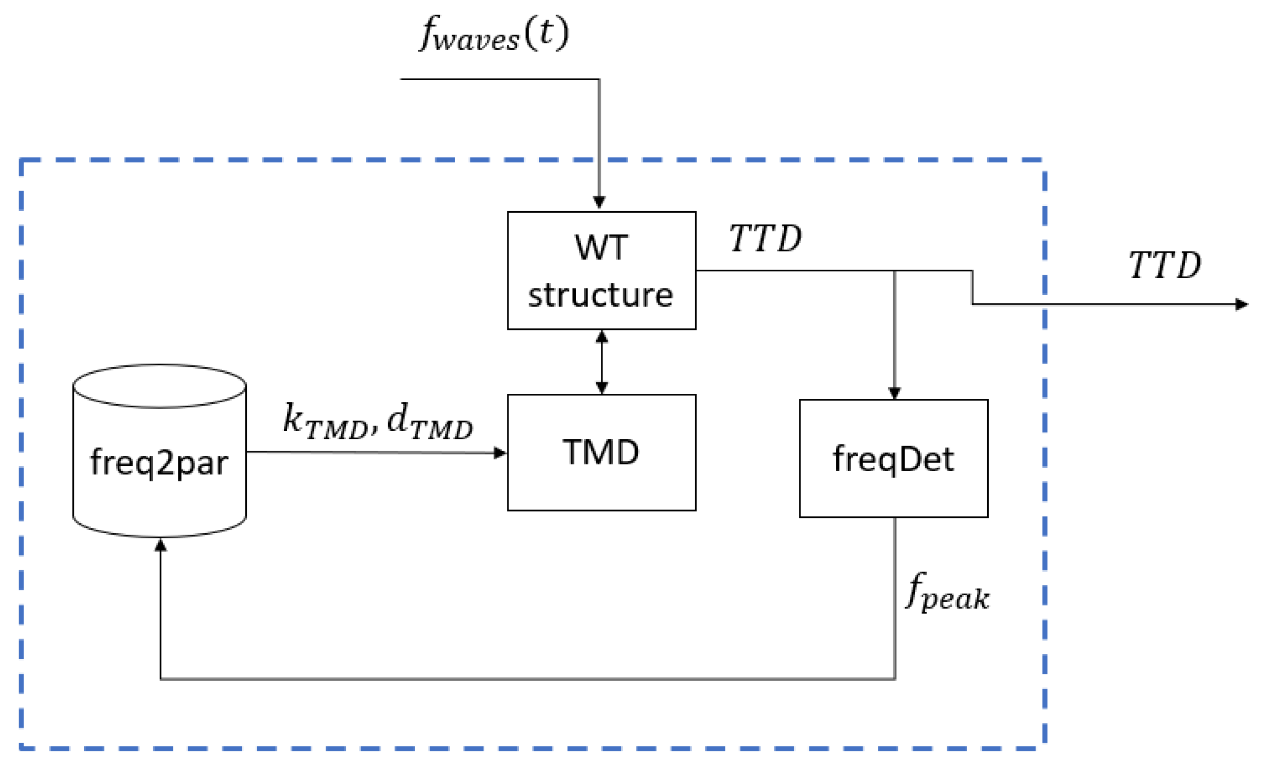
Following the completion of the optimization, the frequency-based semi-active TMD is implemented according to the scheme illustrated in
Figure 8.
The main frequency, , is determined in real time by the frequency detector, freqDet. Details of the frequency detection process are provided in Section Determination of the Frequency in Real Time. The detected frequency is then used as an index in the lookup table to retrieve the corresponding pair of parameters , which are subsequently applied as inputs to the TMD.
Determination of the Frequency in Real Time
In order to adjust the semi-active TMD in real time to any given frequency, it is necessary to identify the current frequency online [
26]. For this purpose, the Short-Time Fourier Transform (STFT) is applied. The STFT is widely used for analyzing non-stationary signals, as it provides an effective time–frequency representation of many signal types [
27]. To determine the frequencies present at a specific moment in time
, a small segment of the signal around that instant is selected, and a Fourier analysis is performed on this segment. This is achieved by multiplying the signal
by a window function
, centered at
, resulting in the modified signal segment, where
represents the current time.
The two time variables that define the modified signal are the current time, , and the time of interest, . The window function is chosen so that the signal contribution is negligible for time periods far from , while remaining effectively constant near . In this study, a Hamming window function was utilized. Multiple simulations were conducted to determine the optimal window length, revealing that the accuracy of the detected frequency is highly sensitive to this parameter. Following extensive testing, the window length was optimized using Genetic Algorithms, yielding a length of 12 s with an overlap of 3.2 s.
By sliding the window along the signal, the data are segmented accordingly. The STFT is then applied to each segment to identify the frequencies present in that specific portion of the signal. This process generates a new spectrum for each time interval.
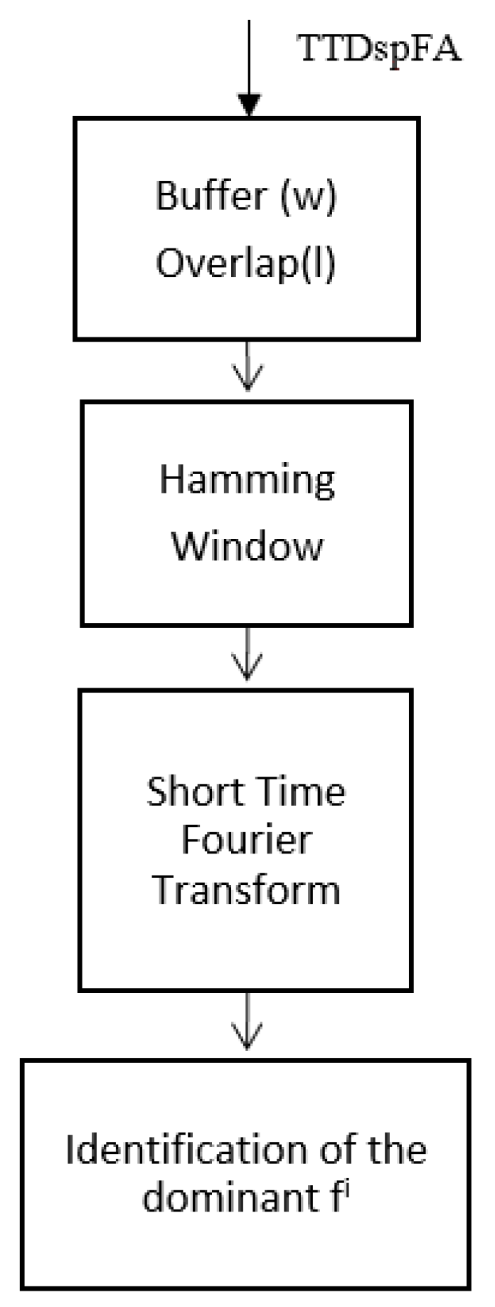
A summary of the method is illustrated in
Figure 9, where TTDspFA represents the tower top displacement (TTD) in the fore–aft direction,
w is the window length (12 s), and
l is the overlap. The resulting signal,
fi, corresponds to the dominant frequency identified for each segment of the signal.
This methodology enables the identification of the operating frequency in real time, allowing the TMD to be optimized for the detected frequency by adjusting its tuning parameters accordingly.
The semi-active TMD dynamically updates its parameters based on the system’s frequency, which is determined using the STFT. This approach has been implemented in the simplified model of the floating wind turbine.
6. Results
6.1. Reduction of Oscillations Caused by Platform Pitch Displacement
In the simulation experiments, the external forces caused by the waves are initially set to zero, and the initial tower displacement is also considered null; the initial platform pitch is 5°. The performance of the passive TMD and the semi-active TMD based on the vibration’s amplitude is now evaluated.
In this context, the optimized parameters for the passive TMD are spring constant = 4868 N/m and damping coefficient = 2419 Ns/m, respectively.
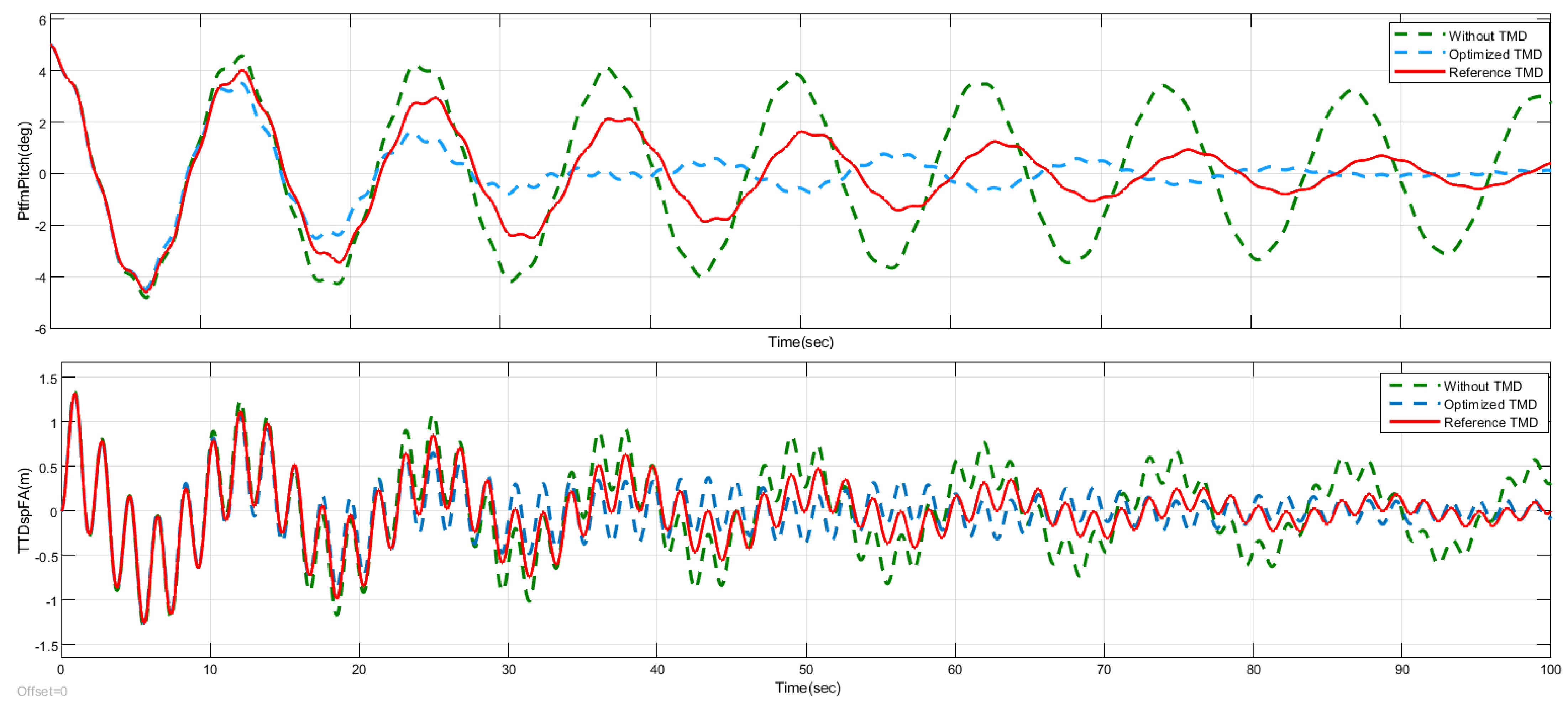
Figure 10 compares the system responses for three cases: with the optimized passive TMD (orange line), without a TMD (blue line), and with the reference TMD presented in [
11] (red line).
A 35% reduction was achieved in the standard deviation of the tower displacement (σTTDFA), decreasing from 0.487 without TMD to 0.317 with the TMD tuned by the Genetic Algorithm (GA). Using the OpenFAST TMD, the suppression rate was 28.6%, while the GA-optimized TMD achieved a 34.9% suppression rate. This clearly demonstrates an improvement in oscillation suppression during free decay tests. The platform pitch also showed similarly promising results, with significantly enhanced stability of the barge when using the improved TMD.
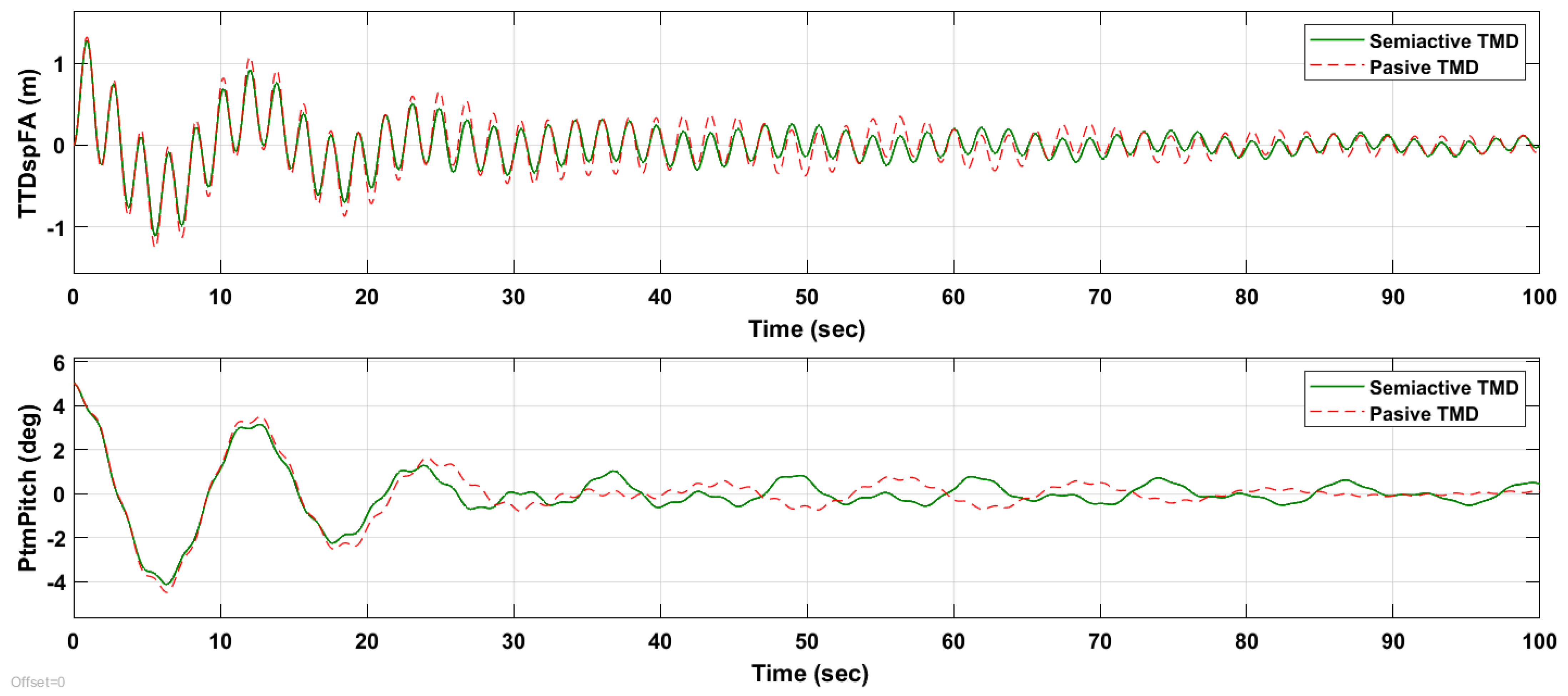
After evaluating the performance of the optimized passive TMD, this work investigates whether parameter variation based on amplitude—using the optimized amplitude-based semi-active TMD—could offer further improvements.
Figure 11 presents the TTD (tower top displacement) and platform pitch angle for both the optimized passive TMD (dotted red line) and the optimized amplitude-based semi-active TMD (green line). The comparison was conducted for an initial platform pitch of 5°.
As can be seen in the results, employing a semi-active control strategy based on the amplitude of the oscillations reduces the tower top displacement (σTTDFA) by an additional 16% compared to the case of GA-optimized passive control, yielding a standard deviation of 0.266 versus 0.317 for the passive TMD. The vibration suppression rate achieved by the semi-active control as presented here is 45.4%. This reduction is significant, as it contributes to lowering structural loads, thereby mitigating fatigue and wear on the wind turbine components.
6.2. Reduction of Oscillations Caused by Sea Waves
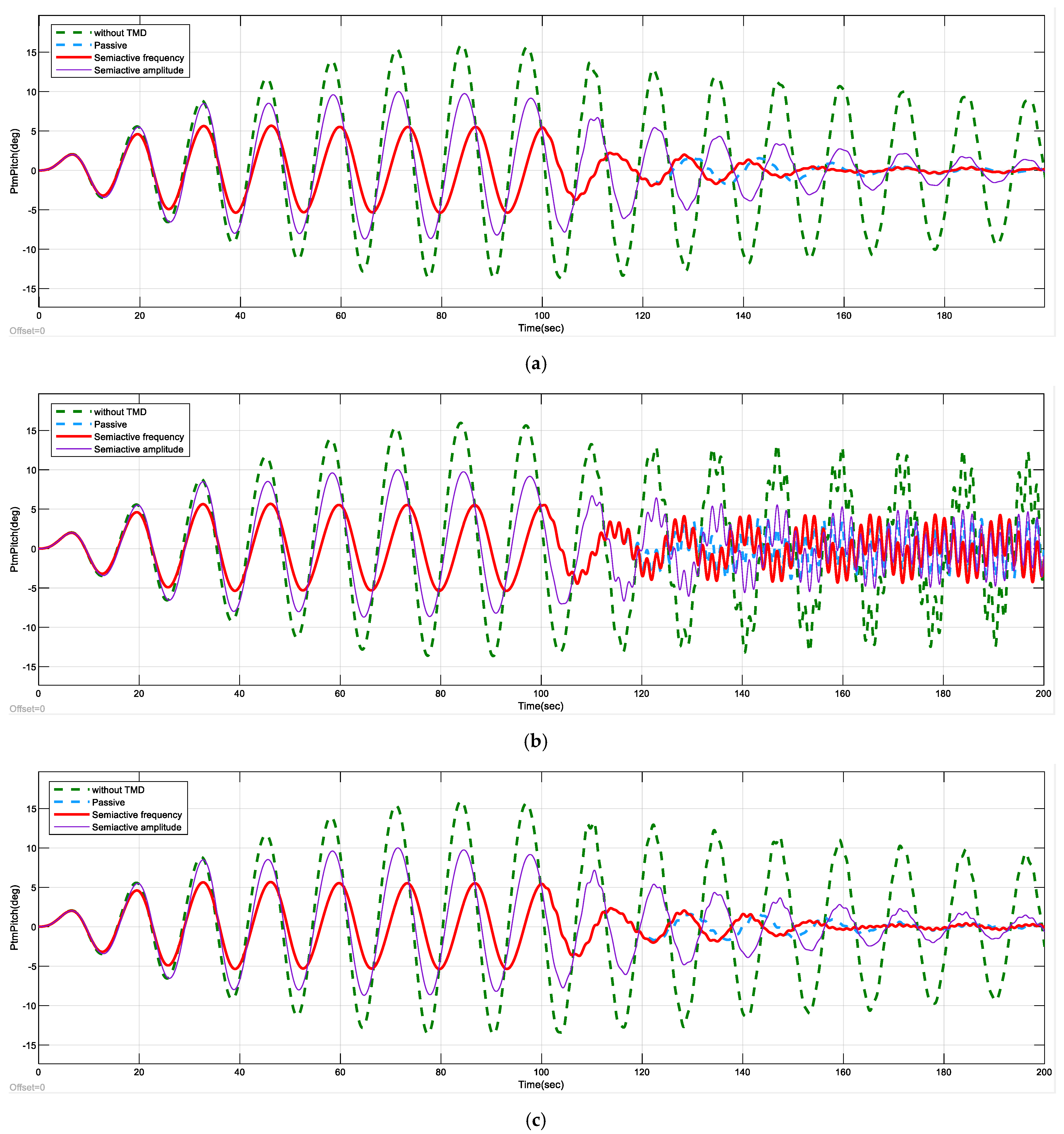
The effect of wave forces was simulated using an external force, as defined in Equation (9), with amplitude and angular frequency . The application of this external force at the edge of the barge generates a moment, as described in Equation (10). In the experiment, the amplitude was set to 90,000 kN, with initially set to 2π × 0.08 rad/s for the first 100 s, then increased to 2π × rad/s for the subsequent 100 s. Both the tower and the platform were initially at rest. Three different experiments are executed using different values of ; these are Hz, Hz and Hz. The frequency of the second main vibration mode of the tower is 0.54 Hz; therefore, these experiments excite this vibration mode.
Figure 12 and
Figure 13 compare the TTD and platform pitch angle obtained with the proposed control strategies. During the first 100 s, the system response is similar for both the passive and the frequency-based semi-active controls. This confirms that the semi-active control successfully detects the current oscillation frequency (0.08 Hz) and assigns the optimal spring stiffness and damping coefficient parameters, which coincide with those of the optimized passive TMD. As a result, both signals appear overlapped in the figure during this period. Only the optimized passive TMD results are included in the figure to avoid clutter, as a comparison with other passive TMD configurations was already presented in
Figure 10.
After 100 s, the frequency of the external force changes to 0.54 Hz, exciting the second main vibration mode of the tower and altering the system response. The tower oscillation amplitude is reduced more effectively by the frequency-based semi-active control (red line) compared to the optimized passive TMD (dashed blue line) and the amplitude-based semi-active control. This demonstrates that the proposed control strategy not only accurately detects the oscillation frequency but also dynamically adjusts the TMD parameters (spring stiffness and damping coefficient) accordingly. These results validate the effectiveness of the proposed control in mitigating wind turbine vibrations.
Table 5 compares the suppression rate of the passive and semiactive strategies. The suppression rate of the frequency-based semi-active control is higher than that of the other strategies. The highest difference appears when the frequency matches the main vibration mode; in this case, the suppression rate of the frequency-based semi-active control is 24.59%, which is significantly higher than that of the optimized passive TMD (2.57%).
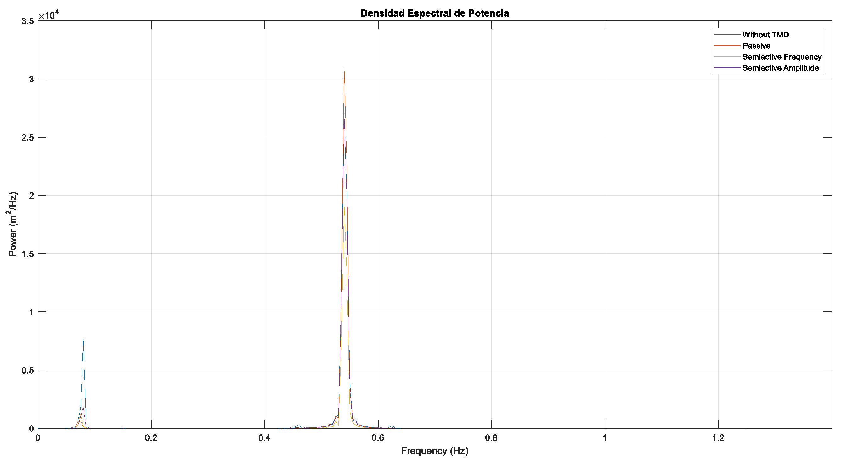
Figure 14 presents a comparison of the power spectral density (PSD) of the TTD for the different TMD strategies when f2 = 0.54 Hz. As expected, two prominent peaks are observed: one at 0.08 Hz and another at 0.54 Hz. The strategy that most effectively dampens the low-frequency peak (0.08 Hz) is the optimized passive TMD. This can be attributed to the fact that the passive TMD was specifically optimized during a free decay test to minimize its standard deviation. In the free decay scenario, the low-frequency oscillation contributes most significantly to the standard deviation, which is why the optimization process targets this frequency. This also explains why the optimized passive TMD performs poorly at the higher frequency (0.54 Hz), resulting in the largest peak at that frequency.
At 0.08 Hz, the values of and for the frequency-based TMD are identical to those of the optimized passive TMD, leading to similar peak magnitudes for both strategies at this frequency. Conversely, at 0.54 Hz, the frequency-based semi-active control demonstrates superior performance, yielding the lowest peak in the PSD, indicating the most effective damping.
Several conclusions can be drawn from these results. Firstly, as expected, the oscillation suppression rates are significantly lower when the system is excited by wave forces compared to the free decay test simulations, due to the consistent excitation introduced by the external force. Although the TMD effectively reduces the TTD, it cannot damp it out entirely, which was expected given the persistent external excitation applied to the system.
Additionally, the optimized passive TMD performs worse than the reference TMD at the 0.54 Hz frequency, contrary to the results observed in simulations where the dominant frequency was 0.08 Hz. This discrepancy may be attributed to the fact that the reference TMD was optimized for an average frequency of 0.3 Hz, making it a more effective strategy for handling frequencies that vary between the two dominant modes of the system.
In conclusion, the proposed frequency-based semi-active control methodology demonstrates good performance, achieving nearly a 25% reduction in vibrations compared to the scenario where the FOWT nacelle is not equipped with a TMD. However, it is important to emphasize that the effectiveness of this control strategy is significantly influenced by the periods of frequency fluctuation. The suppression rates achieved by the semi-active control would be higher if the high-frequency excitation occurred during the transient phase or the initial moments of the simulation, and vice versa.
7. Conclusions and Future Works
In this study, different structural control strategies for FOWT were proposed. First, a simplified model of a floating wind turbine was developed using the Euler–Lagrange approach. The validity of this model was confirmed by comparing it with data from the high-fidelity simulation software OpenFAST, which captures the non-linear dynamics of the wind turbine. Simulations conducted with the simplified model enabled the authors to assess the impact of installing a TMD in the turbine nacelle and to verify its effectiveness in mitigating vibrations. After validating the effect of the passive TMD, its parameters were further optimized using Genetic Algorithms, resulting in an improvement over the performance of the reference TMD.
An initial approach to semi-active control based on the amplitude of vibrations demonstrated the effectiveness of this technique in addressing some of the limitations of passive control. The ability to adapt the TMD parameters to the real-time conditions of the turbine had a significant positive impact on vibration mitigation. This concept was further extended by developing a semi-active control strategy that adjusts the TMD parameters based on the turbine’s pitch rotation frequency. A frequency response analysis of the system highlighted the critical role frequency plays when disturbances are present.
The development of a real-time frequency detection algorithm, utilizing the Short-Time Fourier Transform (STFT), proved effective in identifying the vibration frequency of the turbine under external disturbances. The implementation of frequency-based semi-active control confirmed its potential for reducing vibrations induced by variable-frequency disturbances, such as waves. Additionally, the importance of proper TMD tuning was highlighted, both for passive and semi-active control strategies, as the effectiveness of the results heavily depended on optimal parameter selection.
In summary, TMDs have proven to be effective structural control devices for mitigating vibrations appearing in FOWTs. However, their performance relies heavily on optimal tuning methods to improve the stability of the structure under varying conditions and initial perturbations.
The results here presented suggest exploring additional degrees of freedom and accounting for certain nonlinearities of the TMDs, such as physical stops. Future research will focus on evaluating alternative metaheuristic techniques for optimizing the tuning parameters of the TMD in these control strategies. Furthermore, the authors plan to validate this approach using a scaled-down prototype.
Another promising direction for further research would be to investigate potential practical implementation of these devices. As a matter of fact, existing industrial applications of structural control solutions make use of sensors capable of detecting vibrations or resonances in the structure. These sensors transmit signals to an active damping system, which creates counteracting forces to suppress undesired vibrations. Typically, this is achieved using actuators, such as hydraulic or electromagnetic devices that apply forces to the structure to counterbalance the effects of the vibrations.


 and
and 


