Article

Mechanical and Physicochemical Properties of Ti6Al4V Alloy After Plastic Working and 3D Printing Intended for Orthopedics Implants

Department of Biomaterials and Medical Devices Engineering, Faculty of Biomedical Engineering, Silesian University of Technology, Roosevelta 40 Street, 41-800 Zabrze, Poland
*
Author to whom correspondence should be addressed.
Appl. Sci. 2024, 14(23), 11181; https://doi.org/10.3390/app142311181
Submission received: 14 October 2024 / Revised: 19 November 2024 / Accepted: 25 November 2024 / Published: 29 November 2024
(This article belongs to the Special Issue Recent Advances of Additive Manufacturing in the Modern Industry)

Abstract

:
The aim of this study was to compare the mechanical and physicochemical properties of Ti6Al4V alloy samples produced using 3D printing (Direct Metal Laser Sintering) and bar after plastic working. Both sets of samples were subjected to various surface-processing methods, including sandblasting, heat treatment (hardening for 120 min at 820 ± 10 °C, followed by cooling to room temperature), mechanical polishing, and steam sterilization. This research included macroscopic surface evaluation before and after pitting corrosion resistance tests, metallographic microscopic research, scanning electron microscopy, and energy-dispersive spectroscopy, as well as measurements of hardness, roughness, and surface wettability. The results showed that heat and surface treatment (grinding and mechanical polishing) significantly increased the material’s hardness and corrosion resistance. Furthermore, the steam sterilization process had a positive effect by increasing surface wettability, which is important for biomedical applications, as higher wettability promotes better integration with biological tissues. This is especially relevant in implantology, where surface properties influence osseointegration and overall biocompatibility. In summary, these findings indicate that the selection of manufacturing method and the application of subsequent treatment processes significantly affect the mechanical and physicochemical properties of Ti6Al4V alloy, thereby influencing its performance and suitability for diverse engineering and biomedical applications.

1. Introduction

Over the past few years, additive manufacturing has been developing rapidly. As technology advanced, 3D printing gained popularity, particularly in the areas of filament and metal powder printing. The application of additive manufacturing methods has been found in various sectors of industry, for example, including the automotive, aerospace, shipbuilding industries [1,2].
Additive manufacturing has also found applications in medicine. By recreating the complex structures of organs and bones, doctors can plan operations with greater precision, increasing the safety and effectiveness of procedures [3]. One of the key fields in medicine is biomedical engineering, which has gained significant importance in recent years due to advances in 3D printing technology. Increasingly, the creation of personalized orthopedic implants tailored to specific fractures and dysfunctions of patients, including both humans and animals, is being pursued [4,5,6,7,8,9]. Implants were designed based on images obtained from X-ray or computed tomography (CT) scans, utilizing advanced 3D modeling algorithms and computer simulations. This approach allows for a precise replication of the patient’s anatomy and optimization of the shape and structure of the implant, improving its strength and tissue integration. [10,11,12,13,14]. In the design of orthopedic implants, an important element is to ensure adequate surface roughness, which promotes osteoblast settlement and aids integration of the implant into the bone tissue. On the other hand, in cases where implants are subjected to loads and abrasion, it is necessary to achieve smooth, polished surfaces to minimize friction and material wear, which has a decisive impact on the durability and functionality of the implants in long-term use. Currently, two of the most used methods for manufacturing implants using 3D printing are Selective Laser Melting (SLM) and Direct Metal Laser Sintering (DMLS). The SLM method involves selectively melting metal powder with a laser, allowing for the creation of fully dense, homogeneous structures. In contrast, DMLS is a process where fine metal powder particles are gradually fused together by a laser, leading to solid connections between the particles. This method also relies on layer-by-layer printing, but focuses more on sintering, enabling the production of more complex geometries [15,16,17,18,19,20]. Three-dimensional printing from metal powders, particularly used in the manufacture of medical implants, requires precise control of the process parameters to ensure that the printed components have the right mechanical and structural properties. Key parameters include the power of the laser beam, the speed of the print, and the degree of structure fill. Another commonly used method in implant manufacturing is Powder Bed Fusion (PBF) [21,22].
Using modern materials, such as biocompatible metal alloys (Ti6Al7Nb, Ti13Nb13Zr) and polymers (PEEK), enables the creation of implants that not only meet strength requirements but also physicochemical properties. In particular, the most used biomaterial to produce personalized implants is the titanium alloy Ti6Al4V [23,24,25,26,27]. This alloy is characterized by a favorable combination of mechanical, physicochemical, and tribological properties. It primarily consists of titanium with the addition of 6% aluminum and 4% vanadium [28]. This alloy has found extensive applications in the production of orthopedic implants, such as joint prostheses (permanent implants), and stabilization plates (temporary implants) [29,30,31,32]. It exhibits high strength while maintaining relatively low material density. As a result, implants made from this alloy do not cause rigidity in the skeletal system, thereby preserving proper biomechanics during movement. The properties of the Ti6Al4V alloy, such as its long service life within the body, minimal risk of allergic reactions, resistance to pitting corrosion, and high strength, make it an ideal material for medical applications. Its unique characteristics ensure effective patient therapy while minimizing the risk of complications associated with implantation.
In biomedical engineering, orthopedic implants are also manufactured using traditional methods from titanium bars, such as the Ti6Al4V alloy. The production process for these implants involves precision machining, which allows the implant to be shaped and sized according to the engineering design specifications. After the initial machining, the implant’s surface undergoes additional finishing processes, such as grinding and polishing, and sometimes also specialized techniques to enhance biological and mechanical properties, such as sandblasting or anodizing.
Therefore, the main aim of this research was to compare the mechanical and physicochemical properties of the Ti6Al4V alloy in its state after plastic deformation and after the application of 3D printing technology, considering additional processes such as heat treatment and steam sterilization. This study also aimed to assess whether modern additive technologies could effectively replace traditional orthopedic implant manufacturing techniques, as well as to identify differences in mechanical and physicochemical properties, which could further improve the quality and functionality of implants in medical applications. The conclusions from this study of Ti6Al4V after additive manufacturing could lead to new design guidelines for implants, considering the optimization of manufacturing processes and the improvement in their mechanical and physicochemical properties, which is crucial for the effectiveness of orthopedic therapies.

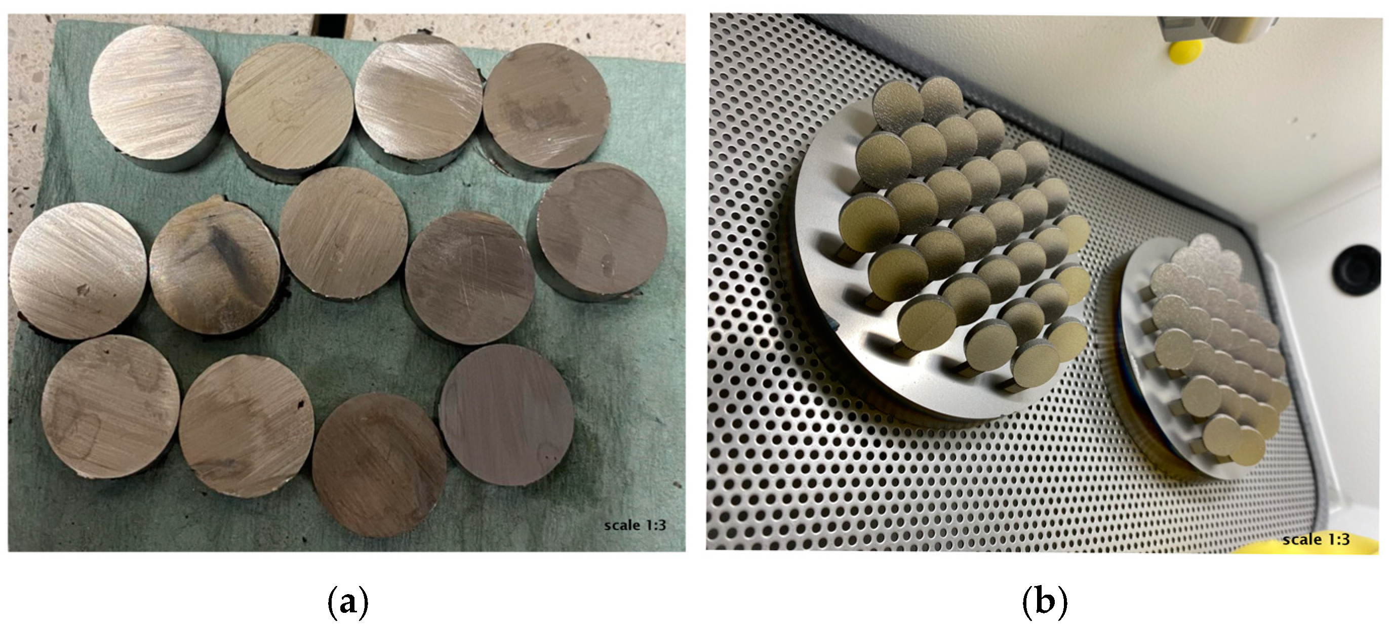
2. Materials and Methods

Ti6Al4V titanium alloy in the state after plastic working and 3D printing was selected for this study. The tests were carried out on 24 samples in the form of disks with a diameter of 14 mm, which were printed on a 3D printer (DMLS samples), and 24 samples from a solid bar with a diameter of 10 mm (PW samples).
The samples were printed on an EOS M100 (EOS GmbH, Krailling, Germany) using the DMLS method according to the parameters and standards found on the material sheet [33]. Each sample had two contours, 100% fill (with the maximum laser beam power being 200W, parameter set as Ti64 20 µm FlexLine 1.x, layer thickness of 20 μm, and volume rate of 1.68mm3/s [33,34,35,36]). Details of the process parameters are proprietary to EOS.
In turn, the bar was cut on a Struers Discotom-10 cutting machine (STRUERS GmbH, Willich, Germany)—Figure 1.
The samples prepared in this way were sandblasted in a “VARIObasic” cabin sandblaster from Renfert. The material used for sandblasting was glass beads, with sizes ranging from 90 to 150 µm. The working pressure was set to 6 bar. Each sample was sandblasted for 120 s. Each time, care was taken to carry out the process in the same way for all samples, maintaining the same distance from the nozzle and an angle of approximately 45 degrees.
The prepared specimens were then machined using a Struers Tegramin-30 automatic grinder–polisher. The surfaces were ground with P400, P500, P1200, P2000 and P4000 abrasive foils. The final processing step involved a mechanical polishing process on a polishing cloth using silicon oxide. The quenching was then carried out on selected samples in a high-vacuum furnace with the following process parameters:
-
Heating of the furnace to a temperature of 820 ± 10 °C;
-
Annealing of the samples for 120 min;
-
Tempering the material to 500 °C with spontaneous cooling of the furnace from 820 °C to room temperature ± 20 °C.
In the final step of sample preparation, medical sterilization was carried out in a Mocom Basic Plus autoclave at a steam temperature of T = 134 °C, at a pressure of 2.10 bar for 12 min. The study samples were divided into eight subgroups, as shown in Table 1.

2.1. Material Structure

In order to reveal the structure, the samples were digested in a solution consisting of 10 mL of hydrofluoric acid and 30 mL of distilled water for 15 s. Observation of the structure of the samples was carried out on a Leica DMi8 A microscope (Laica Microsystems, Wetzlar, Germany) at magnifications of 500× and 1000×.

2.2. Scanning Electron Microscopy and Energy-Dispersive Spectroscopy

The surface assessment was conducted using a SEM (TESCAN VEGA, Brno, Czech Republic), equipped with an SE detector operating at an energy of 10 keV and a zoom of 1000×. The qualitative analysis of chemical composition of the surface layer was analyzed by EDS.

2.3. Surface Roughness

Surface roughness measurements were conducted using a Leica Microsystems optical profilometer with Leica Map softwareLeica Map Premium v.9, which generated detailed reports including surface topography maps and sample profiles. Based on the data obtained, the parameters Sa (in accordance with PN-EN ISO 25178-1:2016-08 [37]) and Ra (in accordance with PN-EN ISO 21920-2:2022-06 [38]) were determined and presented graphically.

2.4. Wettability and Surface Energy

Surface wettability was assessed by measuring the contact angle and surface free energy (SFE) using the Owens–Wendt method. The contact angle measurements were performed with distilled water (by Avantor Performance Materials Poland S.A. (formerly POCH S.A), Gliwice, Poland) and diiodomethane (by Merck, Darmstadt, Germany) on a test stand equipped with a SURFTENS UNIVERSAL goniometer (OEG, Frankfurt Germany) and Surftens 4.5 software for drop image analysis. Measurements were conducted at room temperature (T = 23 °C) on droplets of each liquid placed on the sample surface. Five drops of distilled water and diiodomethane each, 1.5 mL volume each, were placed on the surface of each of the samples. The measurement started 15 s after the drops were dripped. The duration of a single measurement was 60 s at the sampling frequency of 1 Hz. The mean values of the contact angle θav and the surface free energy γS were illustrated graphically.

2.5. Corrosion Resistance and Macroscopic Observations

The pitting corrosion resistance test was carried out using the potentiodynamic method in accordance with the recommendations of PN-EN ISO 10993-15 [39]. In the first stage, the opening potential value Eocp was determined under current-free conditions. In the second stage, polarization curves were recorded.
The measurement setup for conducting this study consisted of the following components: the “VoltaLab PGP201” potentiostat (Radiometer, Villeurbanne Cedex, France), computer with VoltaMaster software 4, an electrochemical cell comprising a Ag/AgCl 3M KCl reference electrode, an auxiliary electrode of platinum, a test electrode of the test sample, 250 mL of PBS solution and the test temperature (T = 37 °C ± 1 °C).
In each case, based on the obtained polarization curves obtained, the corrosion potential was determined using the Stern linear polarization method-(Ecorr [V]), polarization resistance (Rp [kΩ·cm2]) and by simple Tafel extrapolation of the current density (icore [mA/cm2]).
In addition, before and after the corrosion resistance test, surface observations were made on a Leica DVM6 digital microscope at 100× magnification.

2.6. Hardness

Hardness measurement was carried out using the Vickers method on a Struers DuraScan hardness tester at a load of 49N (HV5), in accordance with the recommendations of the PN-EN ISO 6507-1:2007 standard [40]. The test consisted of a series of five measurements for each sample.

2.7. Statistical Analysis

The surface roughness, wettability and surface energy and hardness test results were presented as means with standard deviation. To determine the significance of differences for (p < 0.05), the obtained results used a one-way analysis of variance (ANOVA).

3. Results and Discussion

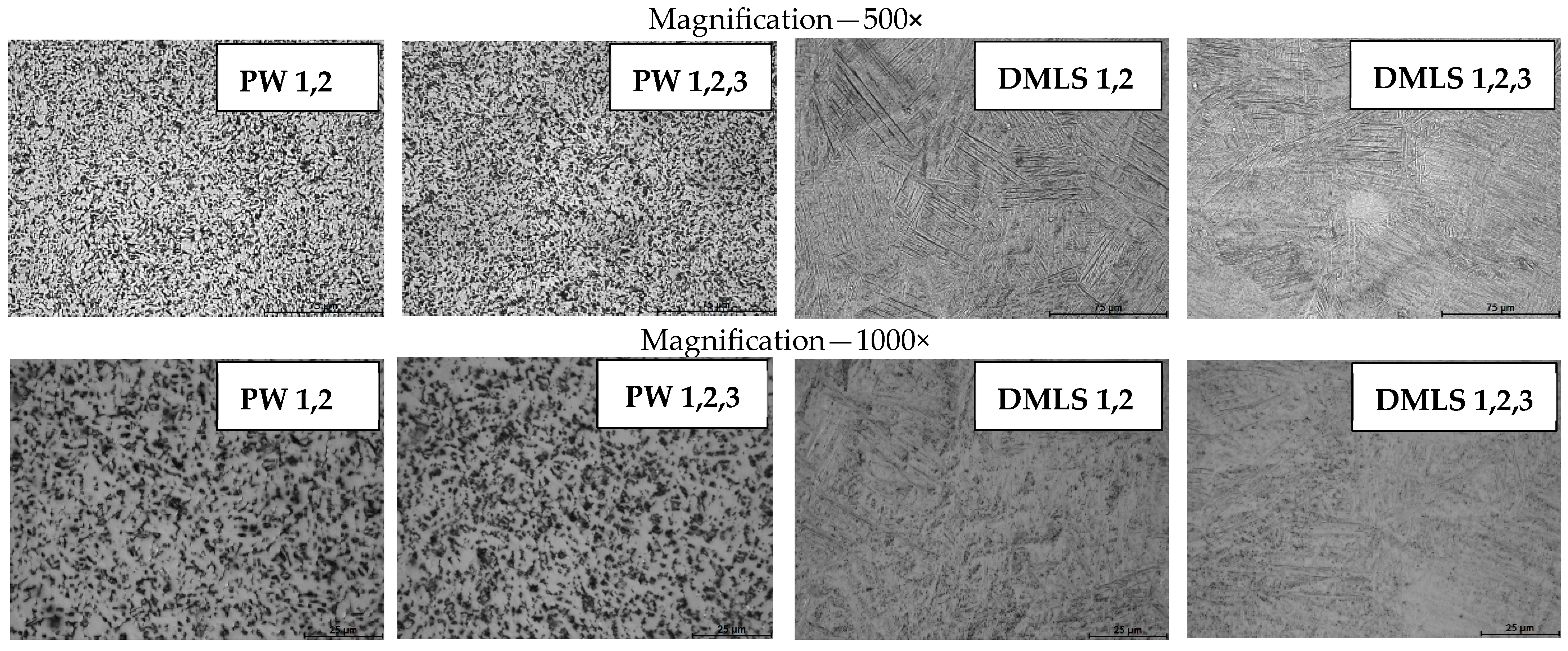
3.1. Material Structure

The results of the observations on the structure of the titanium alloy are shown in Figure 2. For both the bar and the printed samples, a two-phase α+β structure was found. In the case of the bar, there is an equiaxial structure, while in the case of the printed samples, there is a lamellar structure.

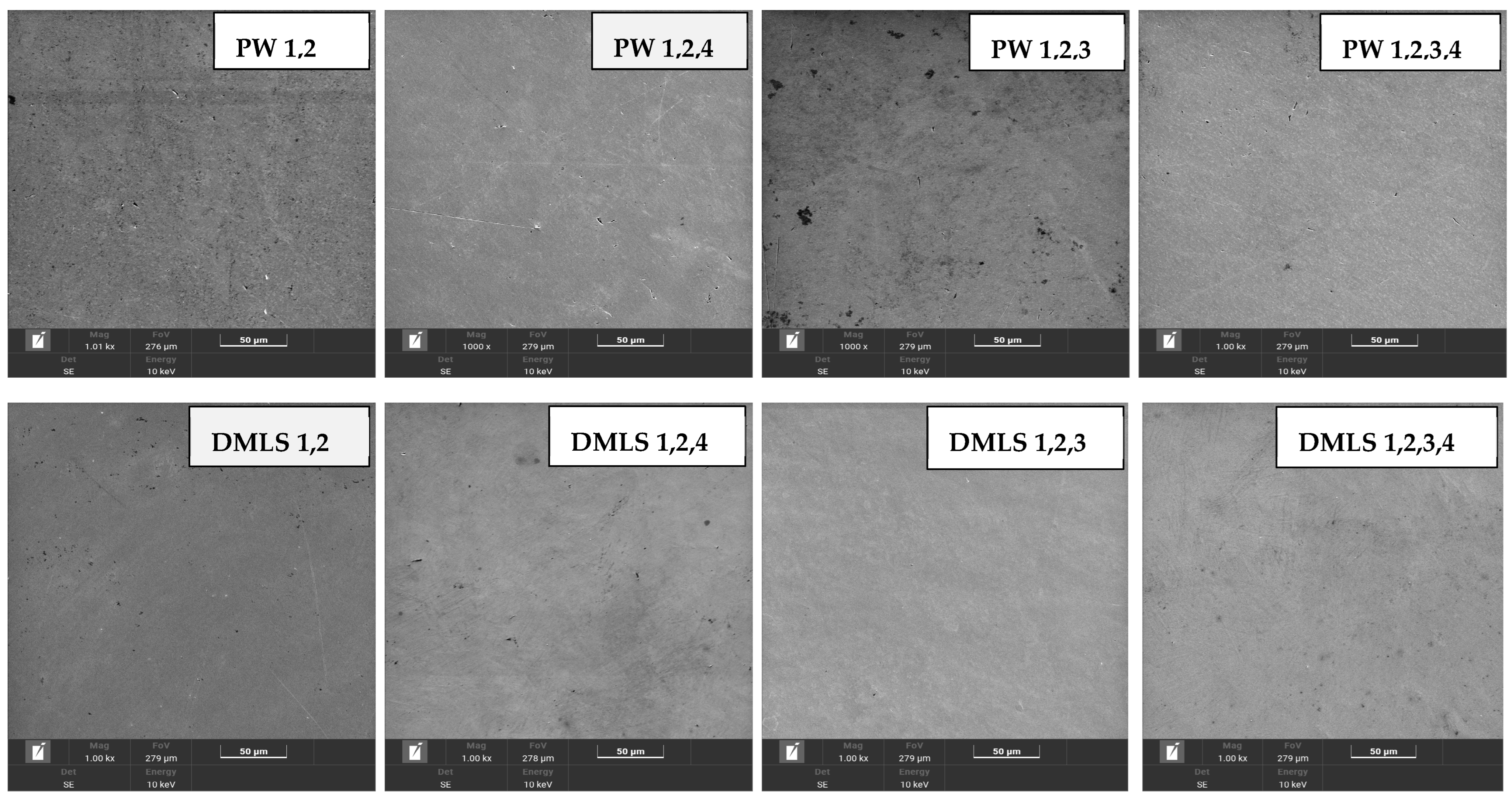
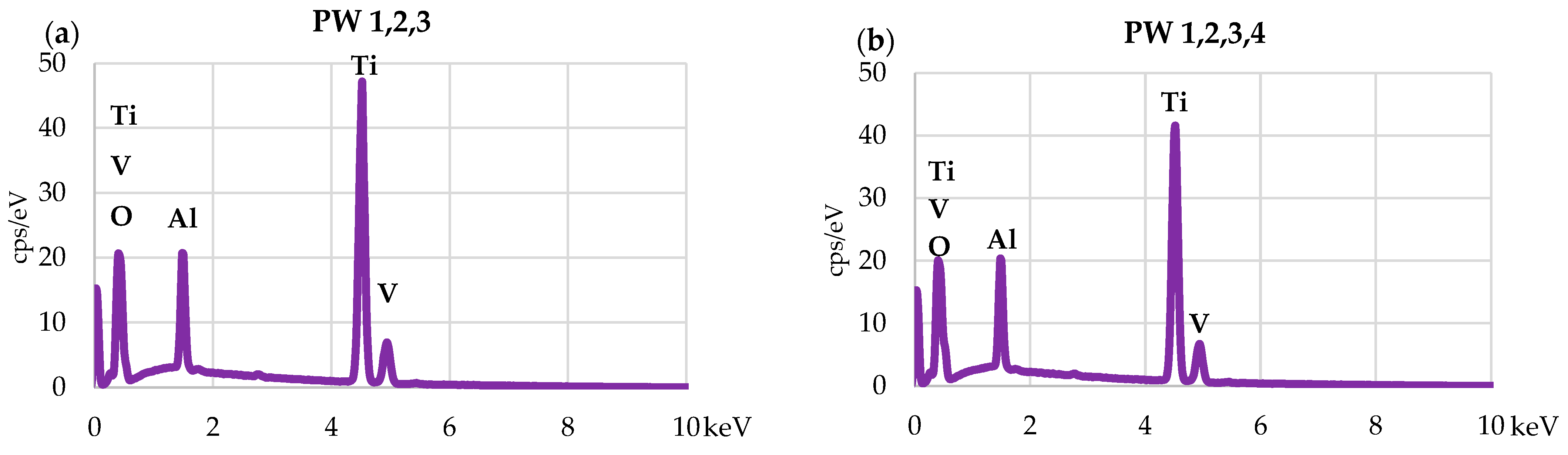
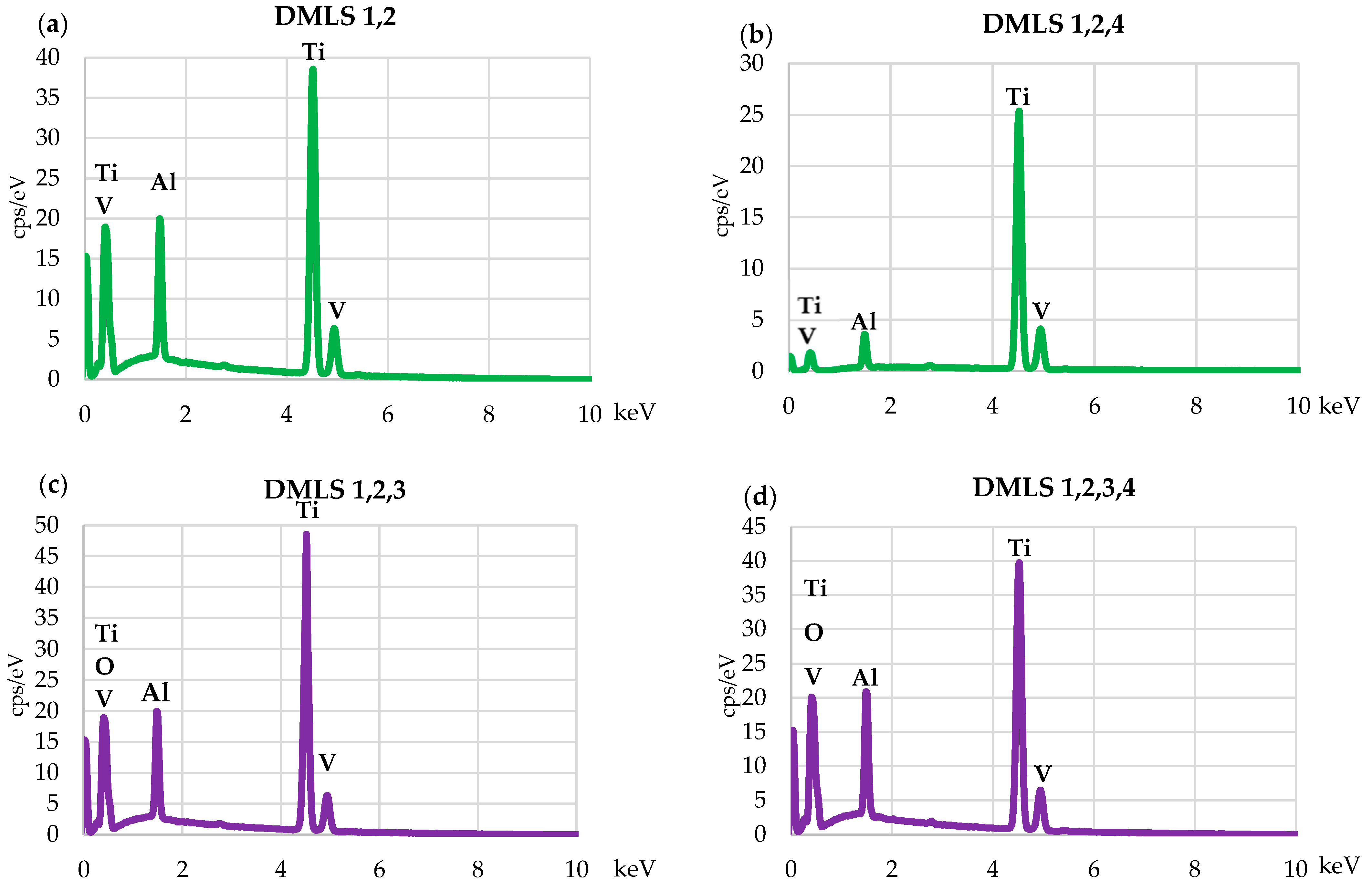
3.2. Scanning Electron Microscopy and Energy-Dispersive Spectroscopy

SEM microscopic observations confirmed that there were no significant differences in the surface of the bar samples after plastic working and 3D printing. This is due to the surface modification of the samples—all samples were mechanically polished after sandblasting. The SEM microscopy images are presented in Figure 3.
The chemical analysis using (EDS) indicated no significant differences in elemental composition between the bar samples after plastic working and the 3D-printed samples. In both groups (labeled as PW 1, 2, 4 and DMLS 1, 2, 4), no elemental oxygen was detected, including in samples DMLS 1,2 and DMLS 1,2,4. The surface layer composition was found to be as follows: Ti (86.4–90.6 wt%), Al (5.1–5.7 wt%), V (3.6–4.1 wt%), and O (3.8–4.7 wt%). Example spectra plots are provided in Figure 4, Figure 5 and Figure 6. However, the outer surface is presented in Table 2.

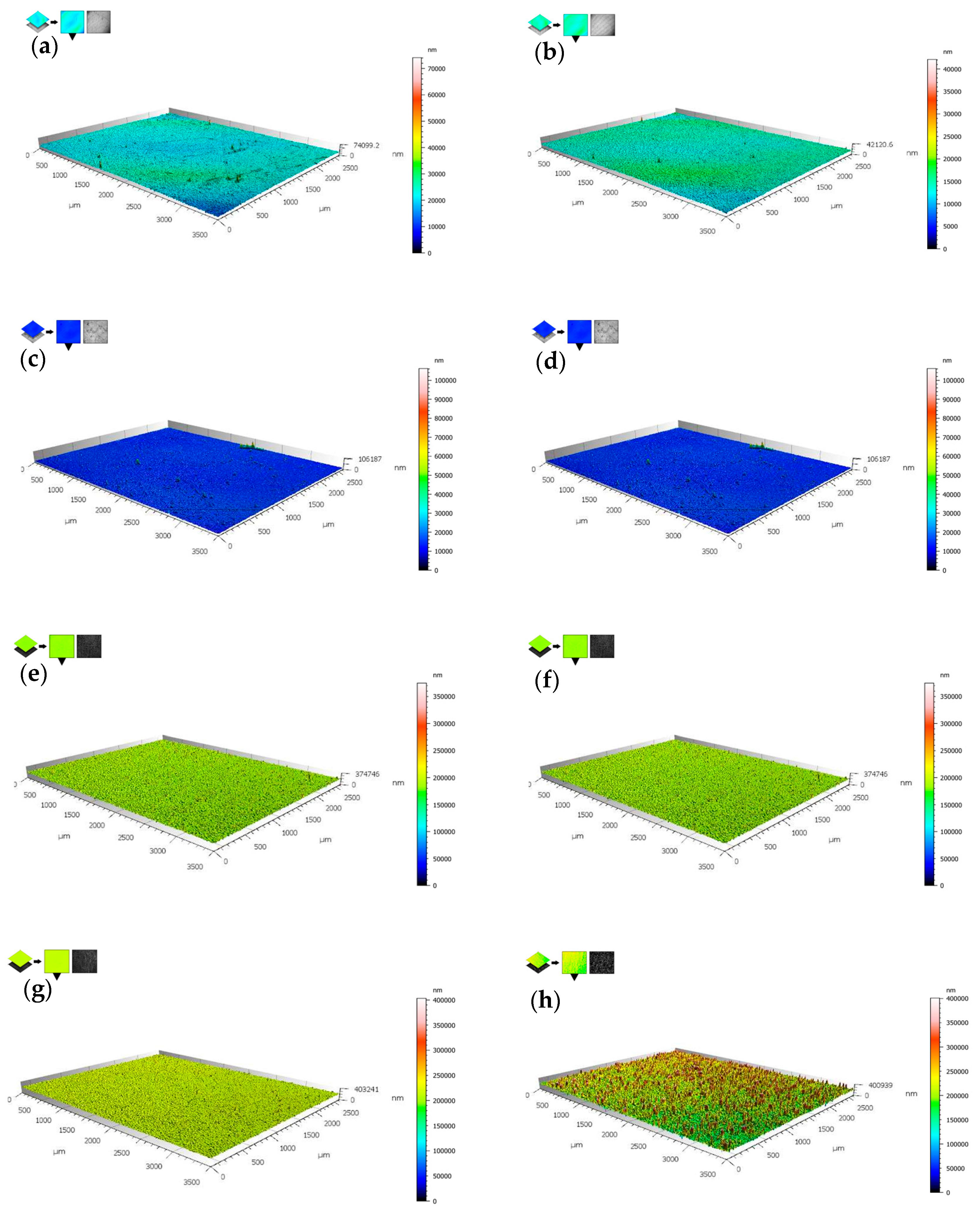
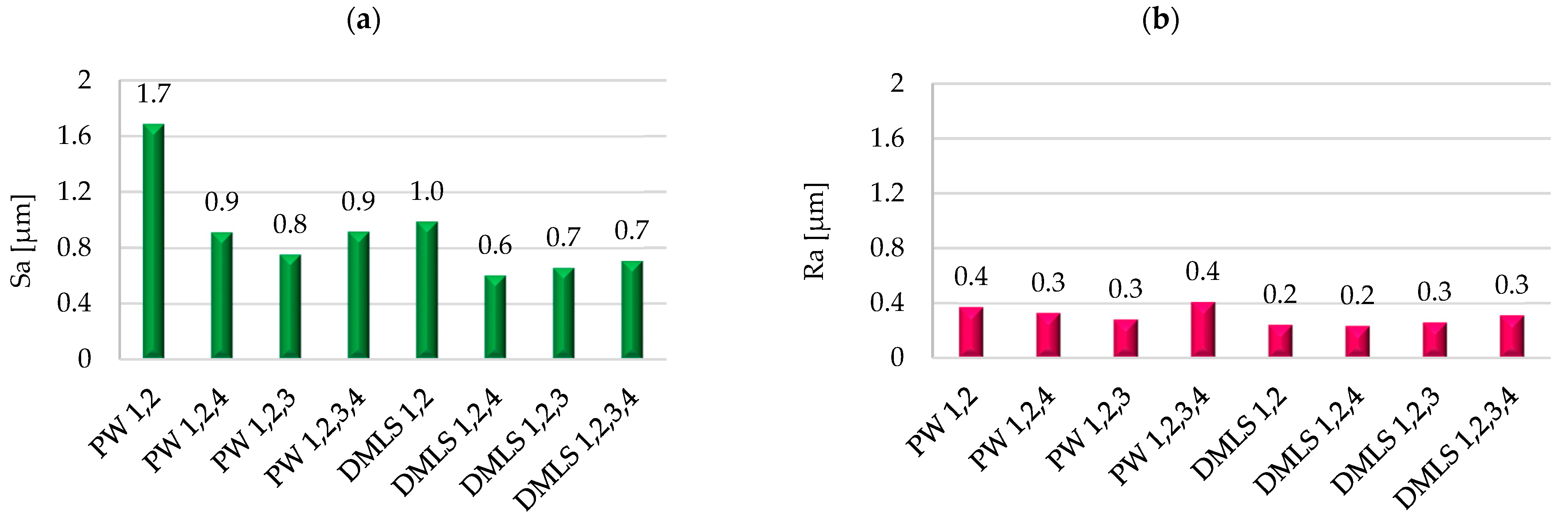
3.3. Surface Roughness

The results of the surface roughness tests are shown in Figure 7. It shows maps of the topography of the test pieces in their initial state (after sandblasting and mechanical polishing, heat treatment and steam sterilization).
A comparison of the values of the surface roughness parameters is shown in Figure 8. The results of the roughness measurements are presented according to ISO 25178 [37] for parameter Sa and ISO 21920 [38] for parameter Ra.
Mechanical surface treatment, including grinding and mechanical polishing, for both groups of samples showed convergent values. Additionally, the samples printed in the initial state are characterized by a lower Sa and Ra parameter compared to the bar after plastic working the samples. In addition, the initial roughness of the samples DMLS printed after sandblasting was also checked—Ra = 11.4 μm. The ANOVA results indicated (p < 0.05) for samples subjected to heat treatment and mechanical polishing compared to those in the initial state for both test groups.

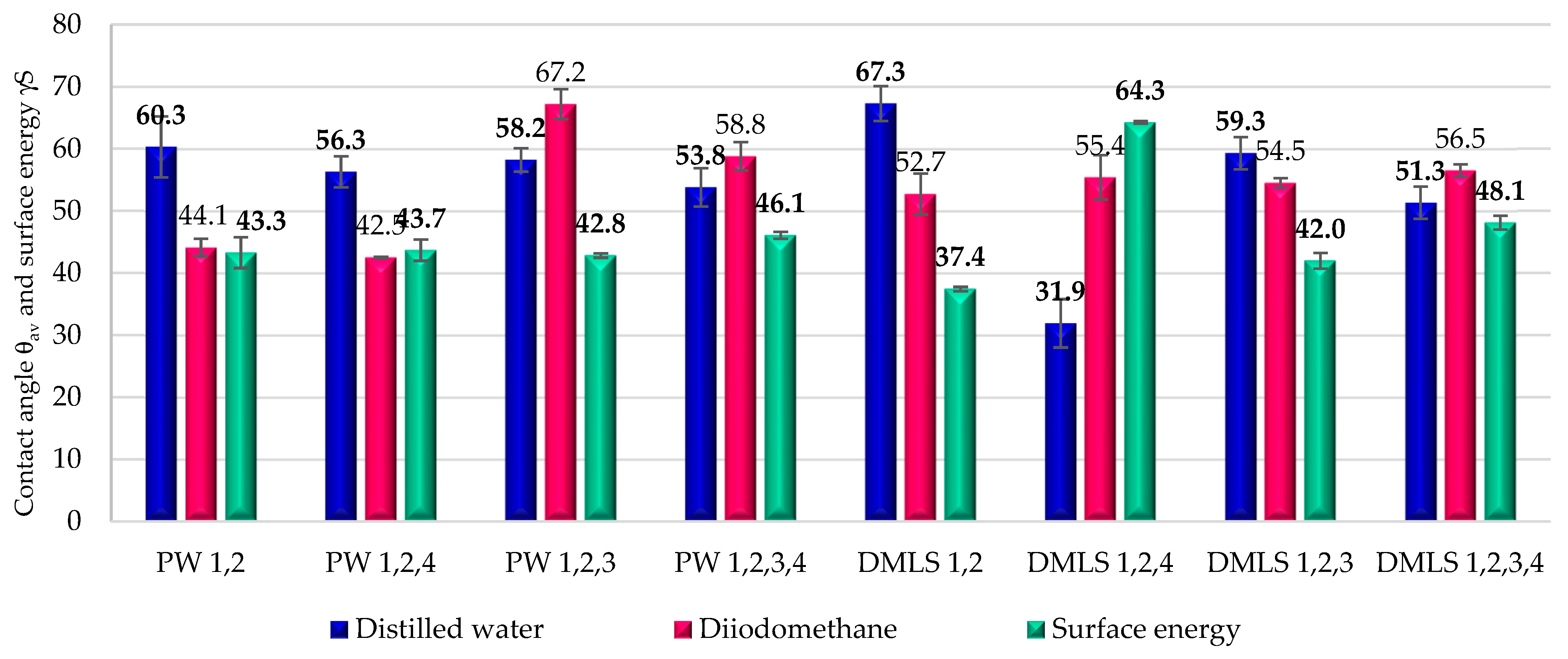
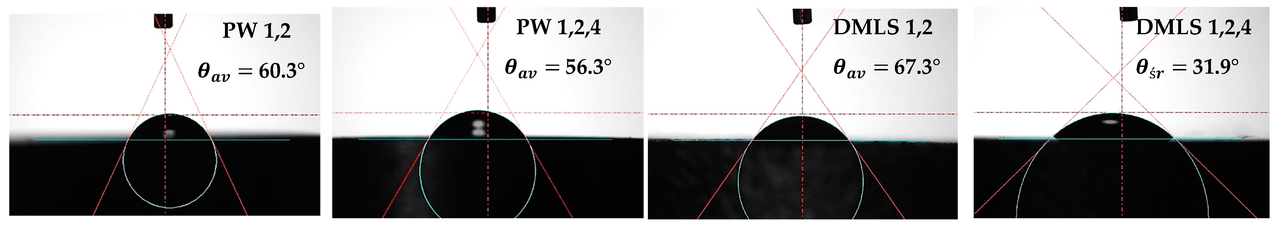
3.4. Wettability and Surface Energy

The average contact angle values θav with distilled water and diiodomethane and the determined average surface energy values γS are shown in Figure 9.
A comparison of example contact angle values for printed and from the bar after plastic working are presented in Figure 10.
From the results obtained, it was found that all the samples tested showed hydrophilic properties, indicating good wettability (Figure 9). No significant effect of steam sterilization and surface energy on the contact angle values for the samples for plastic working was observed. However, a significant change in contact angle after steam sterilization was observed for the DMLS samples (1, 2, 4), which is due to chemical and physical changes that occur on the material surface compared to the samples in the initial condition (p < 0.05).

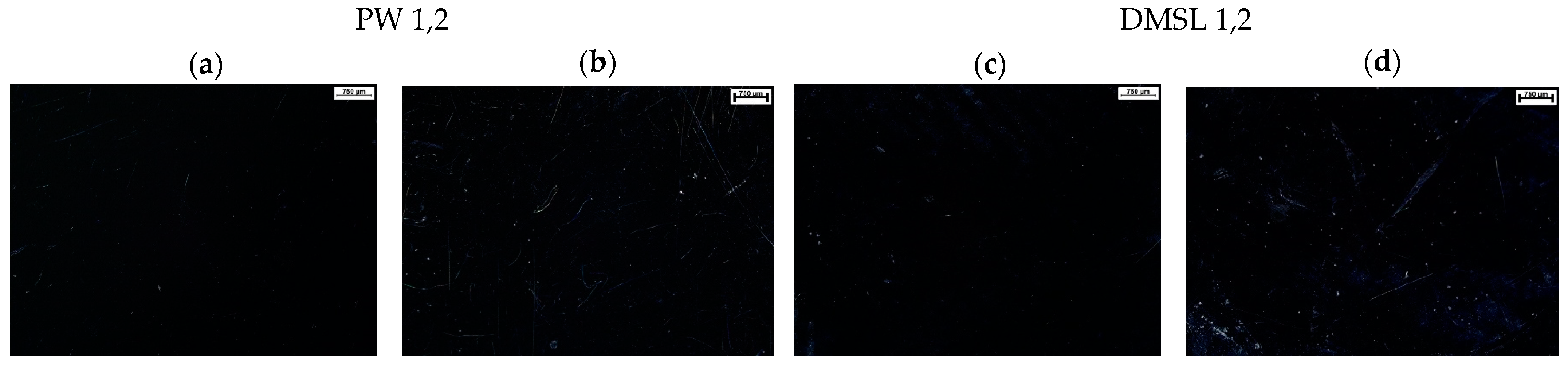
3.5. Corrosion Resistance and Macroscopic Observations
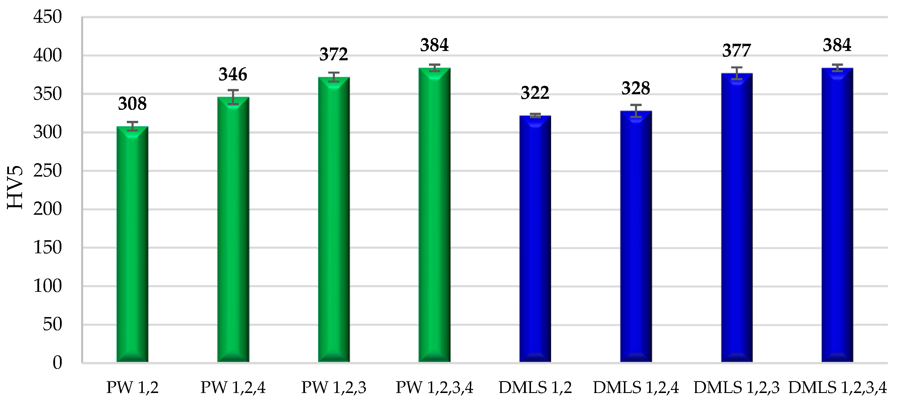
The polarization curves for the bar after plastic working and 3D-printed samples are presented in Figure 11.
The parameters determined from the polarization curves obtained are presented in Table 3.
Based on the graphs obtained and the parameters determined, it was concluded that the Ti6Al4V alloy bar after plastic treatment and the DMLS specimens showed full resistance to pitting corrosion over the entire range tested. Surface treatment, including grinding and mechanical polishing, contributed to improving the corrosion resistance already in the initial state of the samples. In addition, heat treatment also significantly increased corrosion resistance compared to samples not subjected to these processes (p < 0.05). Surface analysis confirmed the absence of corrosion changes and pitting for the samples from both groups.
The surfaces of the printed samples and bar after plastic working are summarized in Figure 12 with 100× zoom.
Black images in microscopy can be the result of optical phenomena associated with a mechanically polished sample surface. Mechanical polishing gives the surface a high degree of smoothness and significantly increases its ability to reflect light in a directional manner.

3.6. Hardness

The 3D-printed DMLS samples and bar after plastic working—the PW samples were prepared and analyzed to assess their mechanical properties. The results of the hardness measurements are presented in Figure 13.
From the results obtained, it was observed that the printed samples (DMLS) in their initial state showed a higher hardness than the bar after plastic working the PW samples. Heat treatment and steam sterilization contributed to an increase in hardness in both cases (p < 0.05) compared to samples in the initial state. The higher hardness of the DMLS samples (DMLS 1,2) in the initial state, compared to the bar after plastic working the samples (PW 1,2) may be due to a minimal difference in the chemical composition of the Ti6Al4V alloy. The titanium powder used for 3D printing additionally contains the element Yttrium (Y), which is not present in PW samples [28,33].
The Ti6Al4V titanium alloy is currently one of the most widely used biomaterials for orthopedic implants. In recent years, the rapid development of 3D printing technology, particularly the SLM and DMSL methods, has significantly accelerated and optimized the manufacturing process of implants and medical devices [23,24,25,29,30,31,32].
All samples were sandblasted before testing. Mechanical grinding and polishing, heat treatment (hardening), and steam sterilization were carried out to modify their surfaces. The sandblasted and mechanically polished samples were marked as baseline materials for analysis. Microstructure images of the Ti6Al4V alloy after etching showed an α-phase with equiaxial spherical grains and a β-phase at 1000× magnification. This microstructure is consistent with the results presented by the authors [41,42]. A two-phase lamellar structure was observed for the “DMLS” samples [33]. As regards the heat-treated samples, no significant change in microstructure was observed for the PW 1,2,3 and DMLS 1,2,3 samples (sandblasted, mechanically polished and heat-treated samples). This may be due to the slow cooling of the furnace from 820 °C to room temperature (±20 °C), which most likely resulted in the restoration of the pre-hardening structure. Based on SEM microscopic observations, no significant differences were observed in the surface of the 3D-printed samples and the samples obtained from the bar after plastic working. This may be since the samples in their initial state had already undergone sandblasting and mechanical polishing. EDS analysis also showed no significant differences in the chemical composition between the materials being tested.
In [26], the authors observed the presence of small spheres on the surface of the examined samples, which is most likely the result of incomplete melting of the Ti6Al4V powder used for implant production. It is also important to note that the implant studied by the authors was a scaffold with a porous structure, which is why its surface was not subjected to the final polishing process, as was the case with the samples analyzed in this article.
To determine the differences in physicochemical and mechanical properties, surface roughness and wettability, corrosion resistance with macroscopic evaluation and hardness measurements were carried out. The highest values of the roughness parameters Sa and Ra were recorded for the initial condition (bar after plastic working). The remaining results were quite similar, as surface treatment reduced the roughness of the specimens from both groups, regardless of the manufacturing process used for the materials (Figure 7). Steam sterilization reduced the roughness of the samples, except for the printed samples and bar after plastic working, which were sandblasted and then heat-treated and steam-sterilized [43]. The contact angle with distilled printed and Ti6Al4V bar samples after plastic working was analyzed using the sitting drop method (Figure 9). The steam sterilization process influenced reducing the contact angle in all cases, indicating that the surface becomes more hydrophilic, although the Ra parameter for roughness increases. The lowest wettability angle, and therefore the highest surface energy, was recorded for DMLS samples 1, 2, 4. This is due to the surface modifications that occur during steam sterilization. Steam sterilization can lead to the formation of a more homogeneous and hydrophilic oxide layer on the surface of the material. This layer increases the surface energy by improving the material’s ability to interact with water molecules, resulting in a lower contact angle [44].
Surface treatments such as grinding and mechanical polishing also significantly affect the change in contact angle; the greatest change was observed in samples printed after mechanical polishing, which had the lowest value of the Ra parameter (baseline samples). The pitting corrosion resistance test showed that both specimens made from bar after plastic working samples and DMLS-printed specimens exhibit pitting corrosion resistance over the entire measurement range. The results obtained for the printed specimens in the initial state are in accordance with the data presented by the authors [42,45]. The corrosion potential, determined during the authors’ own pitting corrosion resistance tests, was Ecor = −0.130 V, while in this publication, the value was Ecor = −0.131 V. Surface treatments such as sandblasting lead to the formation of an unstable and very thin surface layer, which can contribute to the initiation of pitting in the structure of the test material. Therefore, it can be concluded that mechanical polishing, both in the case of bar and printed samples, significantly increased the resistance to pitting corrosion. To confirm the results of the pitting corrosion resistance tests, a surface analysis of the specimens was carried out before and after the corrosion tests. The results of this analysis are shown in Figure 11. Surface analysis confirmed the absence of corrosion changes and pitting for samples from both groups.
From the results obtained, it was observed that the printed samples in their initial state showed a higher hardness than the bar samples after plastic working. This is related to the different mechanical properties and chemical composition of the material, which are described in detail in [28,33]. Heat treatment and steam sterilization contributed to an increase in hardness in both cases (p < 0.05) compared to samples in the initial state. In [46], the authors performed heat treatments at 700 °C, 950 °C, and 1000 °C. Samples treated at 700 °C exhibited hardness values like those of the initial material. In contrast, those treated at 950 °C showed a decrease in hardness. Meanwhile, samples treated at 1000 °C demonstrated an increase in hardness. In this study, the samples were heat-treated at 820 °C, which may have resulted in changes to the microstructure and, consequently, an increase in hardness. However, this remains a hypothesis, as the authors of the referenced article did not conduct hardness measurements for samples treated at 820 °C. Furthermore, the results obtained in this study fall within the range in [46].

4. Conclusions

In summary, the results obtained showed differences in the mechanical and physicochemical properties of Ti6Al4V alloy samples fabricated by 3D printing and from a bar after plastic working. These differences are the result of different fabrication processes that affect the microstructure, surface roughness, and corrosion resistance. Due to the presence of vanadium and aluminum in the studied alloy, further research is planned on other titanium alloys, such as Ti6Al7Nb and Ti13Nb13Zr, to compare differences in the mechanical, physicochemical, and microstructural properties of materials with varying chemical compositions. This research will enable a deeper understanding of the impact of titanium alloy composition on their behavior in biomedical applications, particularly regarding corrosion resistance.

Author Contributions

Conceptualization, W.K. and A.K.; Methodology, A.K.; Software, W.K.; Formal analysis, G.W. and A.K.; Investigation, G.W.; Resources, G.W.; Writing—original draft, G.W. All authors have read and agreed to the published version of the manuscript.

Funding

This research received no external funding.

Institutional Review Board Statement

Not applicable.

Informed Consent Statement

Not applicable.

Data Availability Statement

The original contributions presented in the study are included in the article, further inquiries can be directed to the corresponding author.

Conflicts of Interest

The authors declare no conflict of interest.

References

  1. Savini, A.; Savini, G.G. A short history of 3D printing, a technological revolution just started. In Proceedings of the Conference: 2015 ICOHTEC/IEEE International History of High-Technologies and their Socio-Cultural Contexts Conference (HISTELCON), Tel-Aviv, Israel, 18–19 August 2015. [Google Scholar]
  2. Tuli, N.T.; Khatun, S.; Rashid, A.B. Unlocking the future of precision manufacturing: A comprehensive exploration of 3D printing with fiber-reinforced composites in aerospace, automotive, medical, and consumer industries. Heliyon 2024, 10, e27328. [Google Scholar] [CrossRef] [PubMed]
  3. Christensen, A. Chapter 1—An Abbreviated History of Medical 3D Printing. In 3D Printing for the Radiologist; Elsevier: Amsterdam, The Netherlands, 2022; pp. 1–10. [Google Scholar] [CrossRef]
  4. Paramasivam, V.; Sindhu Singh, G.; Santhanakrishnan, S. 3D Printing of Human Anatomical Models for Preoperative Surgical Planning. Procedia Manuf. 2020, 48, 684–690. [Google Scholar] [CrossRef]
  5. Meng, M.; Wang, J.; Huang, H.; Liu, X.; Zhang, J.; Li, Z. 3D printing metal implants in orthopedic surgery: Methods, applications and future prospects. J. Orthop. Transl. 2023, 42, 94–112. [Google Scholar] [CrossRef] [PubMed]
  6. Wu, Y.; Liu, J.; Kang LTian, J.; Zhang, X.; Hu, J.; Huang, Y.; Liu, F.; Wang, H.; Wu, Z. An overview of 3D printed metal implants in orthopedic applications: Present and future perspectives. Heliyon 2023, 9, e17718. [Google Scholar] [CrossRef]
  7. Memarian, P.; Pishavar, E.; Zanotti, F.; Trentini, M.; Camponogara, F.; Soliani, E.; Gargiulo, P.; Isola, M.; Zavan, B. Active Materials for 3D Printing in Small Animals: Current Modalities and Future Directions for Orthopedic Applications. Int. J. Mol. Sci. 2022, 23, 1045. [Google Scholar] [CrossRef]
  8. Fashanu, F.F.; Marcellin-Little, D.J.; Linke, B.S. Review of surface finishing of additively manufactured metal implants. In Proceedings of the ASME 2020 15th International Manufacturing Science and Engineering Conference MSEC2020, Virtual, 3 September 2020; pp. 2–8. [Google Scholar] [CrossRef]
  9. Alqutaibi, A.Y.; Alghauli, M.A.; Aljohani, M.H.A.; Zafar, M.S. Advanced additive manufacturing in implant dentistry: 3D printing technologies, printable materials, current applications and future requirements. Bioprinting 2024, 42, e00356. [Google Scholar] [CrossRef]
  10. Murr, L.E. Metallurgy principles applied to powder bed fusion 3D printing/additive manufacturing of personalized and optimized metal and alloy biomedical implants: An overview. J. Mater. Res. Technol. 2020, 9, 1087–1103. [Google Scholar] [CrossRef]
  11. Brandl, B.; Eder, S.; Palanisamy, A.; Heupl, S.; Terzic, I.; Katschnig, M.; Nguyen, T.; Senck, S.; Roblegg, E.; Spoerk, M. Toward high-resolution 3D-printing of pharmaceutical implants—A holistic analysis of relevant material properties and process parameters. Int. J. Pharm. 2024, 660, 124356. [Google Scholar] [CrossRef]
  12. Singh, H.N.; Agrawal, S.; Kuthe, A.M. Design of customized implants and 3D printing of symmetric and asymmetric cranial cavities. J. Mech. Behav. Biomed. Mater. 2023, 146, 106061. [Google Scholar] [CrossRef]
  13. Zhai, Y.; Zhang, H.; Wang, J.; Zhao, D. Research progress of metal-based additive manufacturing in medical implants. Rev. Adv. Mater. Sci. 2023, 62, 20230148. [Google Scholar] [CrossRef]
  14. Mehboob, H.; Tarlochan, F.; Mehboob, A.; Chang, S.-H.; Ramesh, S.; Harun, W.S.W.; Kadirgama, K. A novel design, analysis and 3D printing of Ti-6Al-4V alloy bio-inspired porous femoral stem. J. Mater. Sci. Mater. Med. 2020, 31, 1–14. [Google Scholar] [CrossRef] [PubMed]
  15. Chang, J.Z.C.; Tsai, P.I.; Kuo, M.Y.P.; Sun, J.S.; Chen, S.Y.; Shen, H.H. Augmentation of DMLS Biomimetic Dental Implants with Weight-Bearing Strut to Balance of Biologic and Mechanical Demands: From Bench to Animal. Materials 2019, 12, 164. [Google Scholar] [CrossRef] [PubMed]
  16. Humnabad, P.; Das, I.; Tarun, R. An overview of direct metal laser sintering (DMLS) technology for metal 3D printing. J. Mines Met. Fuels 2022, 70, 127–133. [Google Scholar] [CrossRef]
  17. Longhitano, G.A.; Larosa, M.A.; Munhoz, A.L.J.; de Carvalho Zavagliaa, C.A.; Ierardi, M.C.F. Surface Finishes for Ti-6Al-4V Alloy Produced by Direct Metal Laser Sintering. Mater. Res. 2015, 18, 838–842. [Google Scholar] [CrossRef]
  18. Larosa, M.A.; Jardini, A.L.; de Carvalho Zavaglia, C.A.; Kharmandayan, P.; Calderoni, D.R.; Filho, R.M. Microstructural and Mechanical Characterization of a Custom-Built Implant Manufactured in Titanium Alloy by Direct Metal Laser Sintering. Adv. Mech. Eng. 2014, 6, 945819. [Google Scholar] [CrossRef]
  19. Danielli, F.; Berti, F.; Nespoli, A.; Presti, V.L.; Sironi, E.; Ninarello, D.; Villa, T.; Petrini, L. Additive manufacturing for orthopedic implants: Morphological and material characterization of SLM thin Ti6Al4V samples. Procedia Struct. Integr. 2024, 56, 82–89. [Google Scholar] [CrossRef]
  20. Walker, P.; Malz, S.; Trudel, E.; Nosir, S.; ElSayed, M.S.A.; Kok, L. Effects of Ultrasonic Impact Treatment on the Stress-Controlled Fatigue Performance of Additively Manufactured DMLS Ti-6Al-4V Alloy. Appl. Sci. 2019, 92, 787. [Google Scholar] [CrossRef]
  21. Koju, N.; Niraula, S.; Fotovvati, B. Additively Manufactured Porous Ti6Al4V for Bone Implants: A Review. Metals 2022, 12, 687. [Google Scholar] [CrossRef]
  22. Nelson, K.; Kelly, C.N.; Gall, K. Effect of stress state on the mechanical behavior of 3D printed porous Ti6Al4V scaffolds produced by laser powder bed fusion. Mater. Sci. Eng. B 2022, 286, 116013. [Google Scholar] [CrossRef]
  23. Gao, P.; Fan, B.; Yu, X.; Liu, W.; Wu, J.; Shi, L.; Yang, D.; Tan, L.; Wan, P.; Hao, Y.; et al. Biofunctional magnesium coated Ti6Al4V scaffold enhances osteogenesis and angiogenesis in vitro and in vivo for orthopedic application. Bioact. Mater. 2020, 5, 680–693. [Google Scholar] [CrossRef]
  24. Peia, X.; Wang, L.; Zhou, C.; Wu, L.; Lei, H.; Fan, S.; Zeng, Z.; Deng, Z.; Kong, Q.; Jiang, Q.; et al. Ti6Al4V orthopedic implant with biomimetic heterogeneous structure via 3D printing for improving osteogenesis. Mater. Des. 2022, 211, 110964. [Google Scholar] [CrossRef]
  25. Orłowska, A.; Kajzer, W.; Goldsztajn, K.; Gawron, A.; Godzierz, M.; Nowińska, K.; Basiaga, M.; Simka, W.; Szewczenko, J. Functionalization of 3D printed Ti6Al4V high-porous spinal implant surface with use of plasma electrolytic oxidation. Appl. Surf. Sci. 2024, 659, 159948. [Google Scholar] [CrossRef]
  26. Orłowska, A.; Szewczenko, J.; Kajzer, W.; Goldsztajn, K.; Basiaga, M. Study of the Effect of Anodic Oxidation on the Corrosion Properties of the Ti6Al4V Implant Produced from SLM. J. Funct. Biomater. 2023, 14, 191. [Google Scholar] [CrossRef]
  27. Li, Y.; Wang, F. Review of 3D-PrintedTitanium-BasedImplants:Materials and Post-Processing. ChemBioEng Rev. 2024, e202400032. [Google Scholar] [CrossRef]
  28. PN-EN ISO 5832-3; Implanty Dla Chirurgii—Materiały Metalowe—Część 3 Stop Tytanu 6−Aluminium 4−Wanad do Przeróbki Plastycznej. ISO: Geneva, Switzerland, 2021.
  29. Zhang, C.; Zhang, H.; Peng, W.; Feng, A.; Hu, J.; Wang, W.; Yuan, H.; Li, Q.; Fu, Q. 3D-printed Ti6Al4V thoracic fusion cage: Biomechanical behavior and strengthening mechanism. J. Mater. Res. Technol. 2024, 31, 2685–2695. [Google Scholar] [CrossRef]
  30. Zhang, T.; Zhou, W.; Yang, W.; Bi, J.; Li, H.; Gao, X.; Zhang, B.; Shi, G.; Li, K.; Wei, Z.; et al. Vancomycin-encapsulated hydrogel loaded microarc-oxidized 3D-printed porous Ti6Al4V implant for infected bone defects: Reconstruction, anti-infection, and osseointegration. Bioact. Mater. 2024, 42, 18–31. [Google Scholar] [CrossRef]
  31. Abd-Elaziem, W.; Darwish, M.A.; Hamada, A.; Daoush, W.M. Titanium-Based alloys and composites for orthopedic implants Applications: A comprehensive review. Mater. Des. 2024, 241, 112850. [Google Scholar] [CrossRef]
  32. Hadad, H.; Boos Lima, F.B.D.J.; Shirinbak, I.; Porto, T.S.; Chen, J.E.; Guastaldi, F.P.S. The impact of 3D printing on oral and maxillofacial surgery. J. 3D Print. Med. 2023, 7, 3DP007. [Google Scholar] [CrossRef]
  33. EOS Titanium Ti64 Grade 23; Material Data Sheet, Metal Solutions; EOS GmbHEOS GmbH—Electro Optical Systems: Krailling, Germany, 2022.
  34. EOS Titanium Ti64 for EOS M 300-4; Material Data Sheet; EOS GmbHEOS GmbH—Electro Optical Systems: Krailling, Germany, 2022.
  35. Instruction EOS M 100; User Manual EOS M100; EOS GmbHEOS GmbH—Electro Optical Systems: Krailling, Germany, 2019.
  36. EOS M100; Parameter Sheet; EOS GmbHEOS GmbH—Electro Optical Systems: Krailling, Germany, 2015.
  37. PN-EN ISO 25178-1:2016-08; Specyfikacje Geometrii Wyrobów (GPS)—Struktura Geometryczna Powierzchni: Przestrzenna—Część 6: Klasyfikacja Metod Pomiaru Struktury Geometrycznej Powierzchni. ISO: Geneva, Switzerland, 2016.
  38. PN-EN ISO 21920-2:2022-06; Specyfikacje Geometrii Wyrobów (GPS)—Struktura Geometryczna Powierzchni: Profil—Część 2: Terminy, Definicje i Parametry Struktury Geometrycznej Powierzchni. ISO: Geneva, Switzerland, 2022.
  39. PN-EN ISO 10993-15; Biologiczna Ocena Wyrobów Medycznych—Część 1: Ocena i Badanie w Procesie Zarządzania Ryzykiem. ISO: Geneva, Switzerland, 2019.
  40. PN-EN ISO 6507-1; Metale. Pomiar Twardości Sposobem Vickersa. Część 1 Metoda Badań. ISO: Geneva, Switzerland, 2018.
  41. Garbacz, H.; Ossowski, M.; Wiecieński PWierzchoń, T.; Kurzydłowski, K.J. Mikrostruktura i właściwości warstw międzymetalicznych na stopie Ti-6Al-4V. Politech. Warsz. 2007, 1, 45–55. [Google Scholar]
  42. Mahlobo, M.G.R.; Chikosha, L.; Olubambi, A. Study of the corrosion properties of powder rolledTi6Al4V alloy applied in the biomedical implants. J. Mater. Res. Technol. 2022, 18, 3631–3639. [Google Scholar] [CrossRef]
  43. Cabrini, M.; Carrozza ALorenzi, S.; Pastore, T.; Testa, C.; Manfredi, D.; Fino, P.; Scenini, F. Influence of surface finishing and heat treatments on the corrosion resistance of LPBF-produced Ti-6Al-4V alloy for biomedical applications. J. Mater. Process. Technol. 2022, 308, 117730. [Google Scholar] [CrossRef]
  44. Park, J.H.; Olivares-Navarrete, R.; Baier, R.E.; Meyer, A.E.; Tannenbaum, R.; Boyan, B.D.; Schwartz, Z. Effect of cleaning and sterilisation on titanium implant surface properties and cellular response. Acta Biomater. 2012, 8, 1966–1975. [Google Scholar] [CrossRef] [PubMed]
  45. Bociąga, D.; Jastrzębski, K.; Olejnik, A.; Świątek, L.; Marchwicka, M. Wpływ wielokrotnej sterylizacji na właściwości biomateriałów. Eng. Biomater. 2016, 19, 11–20. [Google Scholar]
  46. Lekoadi, P.; Tlotleng, M.; Annan, K.; Maledi, N.; Masina, B. Evaluation of Heat Treatment Parameters on Microstructure and Hardness Properties of High-Speed Selective Laser Melted Ti6Al4V. Metals 2021, 11, 255. [Google Scholar] [CrossRef]
Figure 1. (a) Samples cut from the bar after plastic working, (b) DMLS-printed samples.
Applsci 14 11181 g001
Figure 2. The results of the structure assessment.
Applsci 14 11181 g002
Figure 3. Scanning electron microscopy for bar after plastic working and DMLS-printed samples—mag. 1000×.
Applsci 14 11181 g003
Figure 4. Energy-dispersive spectroscopy spectra: (a) PW 1,2, (b) PW 1,2,4.
Applsci 14 11181 g004
Figure 5. Energy-dispersive spectroscopy spectra: (a) PW 1,2,3, (b) PW 1,2,3,4.
Applsci 14 11181 g005
Figure 6. Energy-dispersive spectroscopy spectra: (a) DMLS 1,2, (b) DMLS 1,2,4, (c) DMLS 1,2,3, (d) DMLS 1,2,3,4.
Applsci 14 11181 g006
Figure 7. Maps of the surface topography of the samples generated in Leica Map software: (a) PW 1,2, (b) DMLS 1,2, (c) PW 1,2,4, (d) DMLS 1,2,4, (e) PW 1,2,3, (f) DMLS 1,2,3, (g) PW 1,2,3,4, (h) DMLS 1,2,3,4.
Applsci 14 11181 g007
Figure 8. (a) Results of roughness measurements according to ISO 25178—parameter Sa. (b) Results of roughness measurements according to ISO 21920—parameter Ra.
Applsci 14 11181 g008
Figure 9. Mean values of contact angle θav and surface energy γS for bar after plastic working samples and 3D-printing samples.
Applsci 14 11181 g009
Figure 10. Examples of contact angle drops.
Applsci 14 11181 g010
Figure 11. Logarithmic diagrams for plastic working (PW) and DMLS samples.
Applsci 14 11181 g011
Figure 12. Examples of bar and 3D printing specimen surfaces: (a,c) before pitting corrosion testing, (b,d) after pitting corrosion testing.
Applsci 14 11181 g012
Figure 13. Results of Vickers hardness measurements: bar after plastic working samples (green), DMLS samples (blue).
Applsci 14 11181 g013
Table 1. Division of samples for testing.
1—Sandblasting2—Mechanical Polishing3—Heat
Treatment
4—Steam
Sterilization
PW 1,2xx
PW 1,2,4xx x
PW 1,2,3xxx
PW 1,2,3,4xxxx
DMLS 1,2xx
DMLS 1,2,4xx x
DMLS 1,2,3xxx
DMLS 1,2,3,4xxxx
All baseline samples were after sandblasting and mechanical polishing. In addition, some of the samples were subjected to heat treatment and sterilization, to check whether other material modifications affect the properties of the specimens from the bar after plastic working and 3D-printed samples. PW—plastic working; DMLS—printed samples.
Table 2. Outer surface—energy-dispersive spectroscopy.
SamplesOuter Surface [wt%]
TiAlVO
PW 1,286.45.13.84.7
PW 1,2,490.65.34.1-
PW 1,2,386.85.33.74.2
PW 1,2,3,487.25.13.64.1
DMSL 1,290.45.73.9-
DMSL 1,2,490.65.53.9-
DMSL 1,2,387.15.43.73.8
DMSL 1,2,3,486.45.53.84.3
Table 3. Pitting corrosion resistance results for samples from two groups.
Sample Nameicore
[mA/cm2]
Ecorr
[V]
Rp
[kΩ·cm2]
Av.SDAv.SDAv.SD
PW 1,227520−0.170.0712020
PW 1,2,41812−0.150.0314986
PW 1,2,3365148−0.050.012352
PW 1,2,3,428689−0.030.0412966
DMLS 1,223822−0.1330.05817
DMLS 1,2,447365−0.1350.046516
DMLS 1,2,316245−0.1200.026643
DMLS 1,2,3,424982−0.1160.017821
Av.—average; SD—standard deviation.
Disclaimer/Publisher’s Note: The statements, opinions and data contained in all publications are solely those of the individual author(s) and contributor(s) and not of MDPI and/or the editor(s). MDPI and/or the editor(s) disclaim responsibility for any injury to people or property resulting from any ideas, methods, instructions or products referred to in the content.

