1. Introduction
The pre-stressed high-strength concrete (PHC) nodular pile is a type of PHC pile with variable pile cross-section, and the nodules designed along the shaft with a certain distance is mainly to improve the bearing capacity of the pile. The PHC nodular pile is often used in ground treatment projects in soft soil areas. The bearing capacity of a conventional PHC pipe pile embedded in soft soil areas is generally hampered by the poor engineering properties of soft soils, and the pile shaft strength cannot be fully mobilized. The nodules of a PHC nodular pile can improve the shaft capacity as well as the entire bearing capacity of the pile [
1]. The behavior of a pile with variable cross-section of pile shaft has been investigated by many researchers. In Japan, the behavior of a nodular cylinder pile or muti-node piles has been investigated through model tests [
2,
3]. The test results indicated that the ultimate bearing capacity of a nodular cylinder pile could reach 2.5 times the ultimate bearing capacity of a pipe pile [
2]. Moreover, the effect of nodule number and pile shaft roughness was also investigated through model tests, and the test results showed that the behavior of the nodular pile was affected by soil properties and nodular spacing [
3]. For the pile end capacity, Malik et al. [
4] investigated the end capacity of a straight pipe pile and screw pile under similar environments, and the test results showed that the ultimate capacity of the screw pile was 2–12 times higher than that of the pipe pile.
In North America and Europe, the behavior of the helical pile and screw pile was studied through field tests and numerical simulation [
5,
6,
7,
8]. Sakr [
8] investigated the behavior of helical piles with either a single helix or double helixes installed in oil sand, and the test results confirmed that the helical pile was a viable deep foundation option for the support of heavily loaded structures. Prof. El Naggar [
5,
6] investigated the bearing capacity of helical piles under vertical static and cyclic loading by field tests and numerical simulation, and it could be considered that for the helical pile embedded in clayey soil, the pile–soil relative displacement of helical piles occurred along the diameter of the helix when the helix spacing/helix diameter was less than 3. Moreover, Mohajerani et al. [
9] and Ma et al. [
10] investigated the calculation and design method of screw piles which could be used for the design of screw piles. The helical pile installation process was different from the installation process of conventional driven or hammered PHC piles, and the installation torque was applied on the pile head to overcome the soil resistance as the helical pile advanced into the soil [
11]. Meng et al. [
12] investigated the installation effects of drilled displacement (DD) piles through field tests and proposed that the horizontal soil displacement induced by the installation of a DD pile was mainly within 6D (D is pile diameter).
In China, the PHC nodular pile is normally installed by two installation methods in engineering projects. For the PHC nodular pile with relatively small diameter, it is commonly driven or hammered into the ground directly. Yu et al. [
1] investigated the installation effect and bear capacity of a driven PHC nodular pile, and the test results showed that the disturbance induced by the PHC nodular pile was larger than that of the PHC pipe pile. Moreover, the shaft capacity of the 350 (400) mm PHC nodular pile was about 1.17–1.18 times of the shaft capacity of 400 mm PHC pipe pile. For the PHC nodular pile with relatively large diameter, the PHC nodular pile can be inserted into the pile hole filled with its own weight, and the PHC nodular pile will be surrounded by the cemented soil layer after being cured for the designated time [
13]. Zhou et al. [
14,
15,
16,
17] studied the bearing capacity of a pre-bored grouted planted (PGP) pile through model and field tests, and the test results showed that the compressive and uplift capacity of the PGP pile was better than that of a conventional bored pile because of the cemented soil layer around the PHC pile.
The behaviors of the PHC nodular pile, helical pile and screw pile are proven to be improved compared to that of a conventional PHC pipe pile and bored pile. The installation method of the helical pile and screw pile is different from that of a PHC nodular pile. Moreover, the pile structure of the helical pile and screw pile is also different from the pile structure of a PHC nodular pile, as the helical pile or screw pile shaft only consist of one or several helixes. The bearing capacity of the helical pile and screw pile is different from that of the PHC nodular pile. In recent years, the driven PHC nodular pile has been used in some ground treatment projects, while the theoretical research on driven PHC nodular piles is still limited. Yu et al. [
1] investigated the installation effect and bear capacity of driven PHC nodular piles through a group of field tests. But the test piles were not equipped with strain gauges, and the load transfer mechanism of nodular pile could not be analyzed in depth. The influence of nodules along the pile shaft on the bearing capacity of the PHC pile was also not analyzed due to a lack of test results.
In this paper, the bearing capacity of driven PHC nodular piles was investigated through a group of field tests. Moreover, the ABAQUS simulation was adopted to study the load transfer mechanism of the PHC nodular pile. The influencing factor on the bearing capacity of the PHC nodular pile was also analyzed based on the simulation results. The research results can be used for the design of driven PHC nodular piles in future engineering projects.
2. Field Test Preparation
A group of field tests were conducted in a test site in Ningbo, a coastal city in Southeast China, to study the bearing capacity of driven PHC nodular piles embedded in soft soil layers. In engineering projects, the 350 (400) mm PHC nodular pile (the diameter of nodule is 400 mm, while the diameter of pile shaft is 350 mm) and 450 (500) mm and 550 (600) mm PHC nodular piles are normally adopted in ground treatment projects. The diameter of the nodule is 50 mm larger than the diameter of the pile shaft to reduce the disturbance induced by the installation effect. For the PHC nodular pile adopted in PGP pile, the 600 (800) mm and 500 (650) mm PHC nodular piles are mainly used as the core pile, and the diameter of the nodule is 200 mm and 150 mm larger than the diameter of the pile shaft, respectively. This is because in the PGP pile installation process, the PHC nodular pile is planted into the pile hole under gravity, and the disturbance induced by the PHC nodular pile installation is very limited [
18].
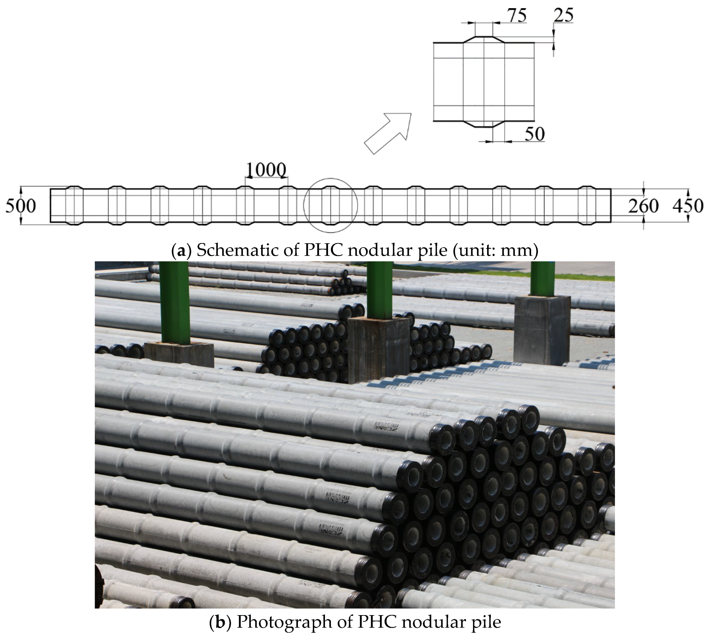
In this research, the 450 (500) mm PHC nodular pile was adopted in the field tests, as shown in
Figure 1. The diameter of pile shaft was 450 mm, and the nodule diameter increased to 500 mm. The thickness of pile shaft wall was 95 mm. Moreover, it can also be seen in
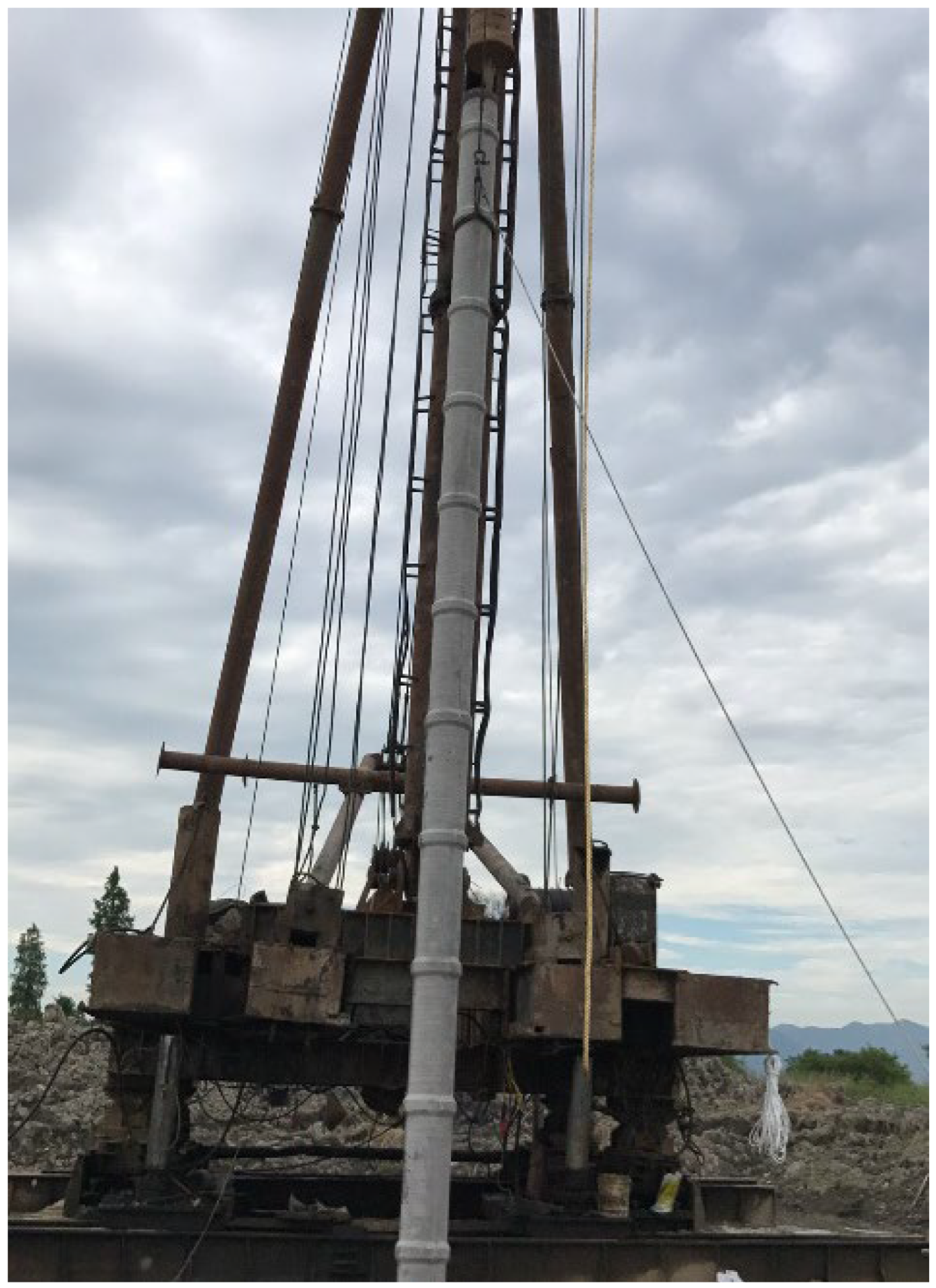
Figure 1 that the height of nodule was 25 mm, and the inclination angle was 26.6°. The distance of the adjacent nodule of 450 (500) mm PHC nodular pile was 1 m, and the ratio of nodular spacing/nodular diameter was 2. The entire length of the test PHC nodular pile was 40 m, and the pile segments were 13 m, 13 m and 14 m long, respectively. The test PHC nodular pile was driven into the ground directly by the piling rig, as shown in
Figure 2.
The soil profiles and properties of the test site are shown in
Table 1, in which
H is the thickness of each soil layer,
γ is unit weight,
w is water content,
e is void ratio,
Es is elastic modulus, which is measured in triaxial tests,
c and
φ are the cohesion and internal friction angle, respectively, which are measured by consolidated-undrained (CU) triaxial tests, and
qsa and
qpa are the ultimate skin friction and unit base resistance for driven PHC pipe pile, which are estimated based on the soil properties according to the local specification [
19]. It can be seen in
Table 1 that the test site consists of deep soft soil, clay and silty clay layers with poor engineering properties. The thickness of two surficial soft soil layers reached 30.3 m, and the cohesion and internal friction angle of two soft soil layers were only around 10 kPa and 10°, respectively. The thickness of the clay layer was 14.2 m, and the cohesion and internal friction angle of the clay layer increased to 27.3 kPa and 15.0°, respectively. The test PHC nodular pile base was located at the clay layer. Moreover, the groundwater level of the test site was about 0.5–1.0 m below the ground surface.
3. Field Test Results Analysis
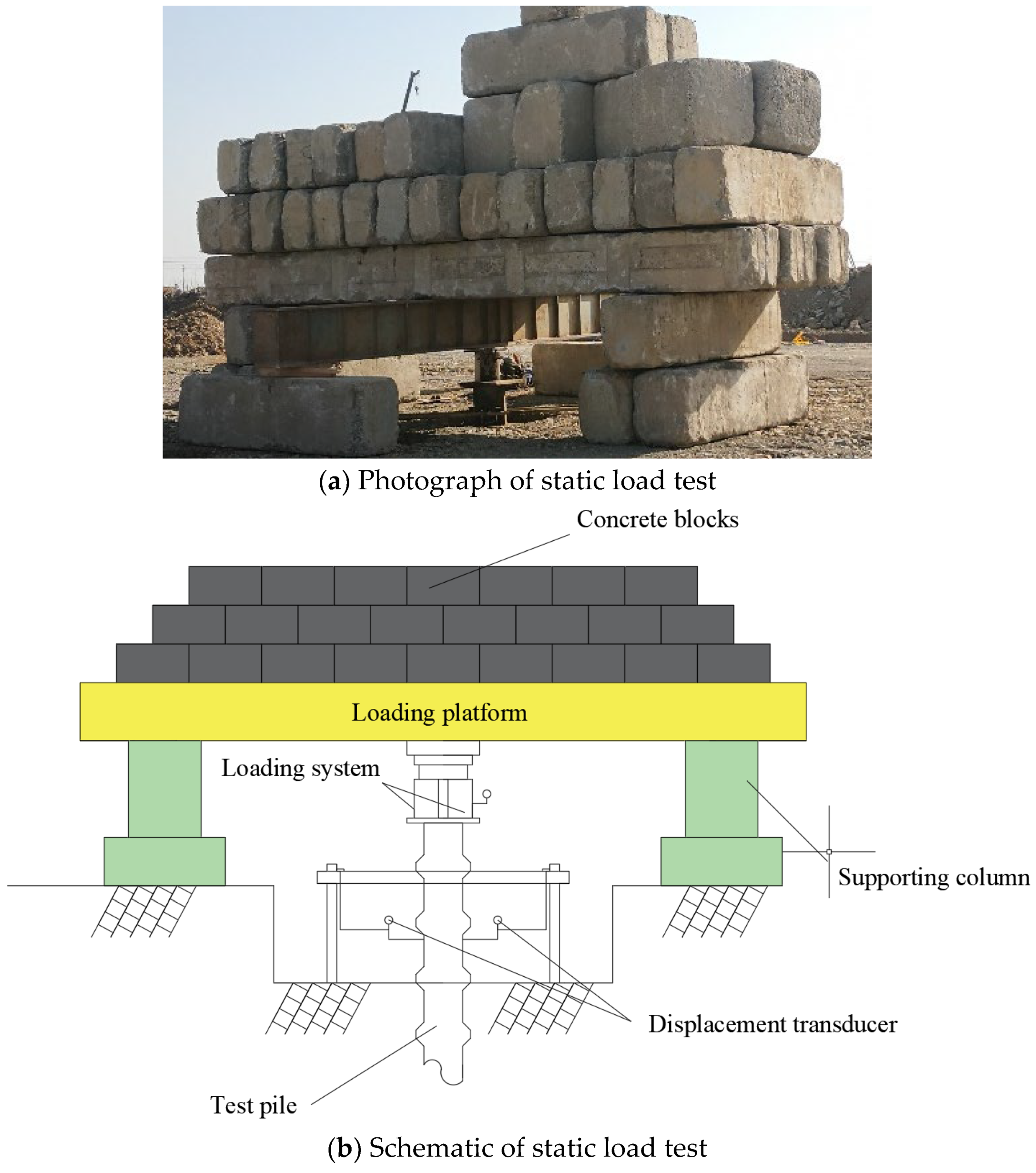
The disturbance induced by PHC nodular pile installation was larger than that of the PHC pipe pile, and the static load tests were conducted 40 days after the installation of test PHC nodular piles. The static load test process referred to the local specification for the testing of building foundation piles [
20], and the slow maintained loading method was adopted in the loading process. The photograph and schematic of the static load test of the PHC nodular pile are presented in
Figure 3.
In total, three PHC nodular piles were adopted for the field tests, and the designed ultimate bearing capacity of the test PHC nodular pile was 1800 kN. In the loading process, the pile head load was applied by two hydraulic jacks with a range of 200 tons. Three displacement transducers with a range of 50 mm were arranged at the test pile head to measure the pile head displacement. To obtain the ultimate bearing capacity of test PHC nodular piles, the static load tests were not terminated until the test pile head displacement was larger than 40 mm.
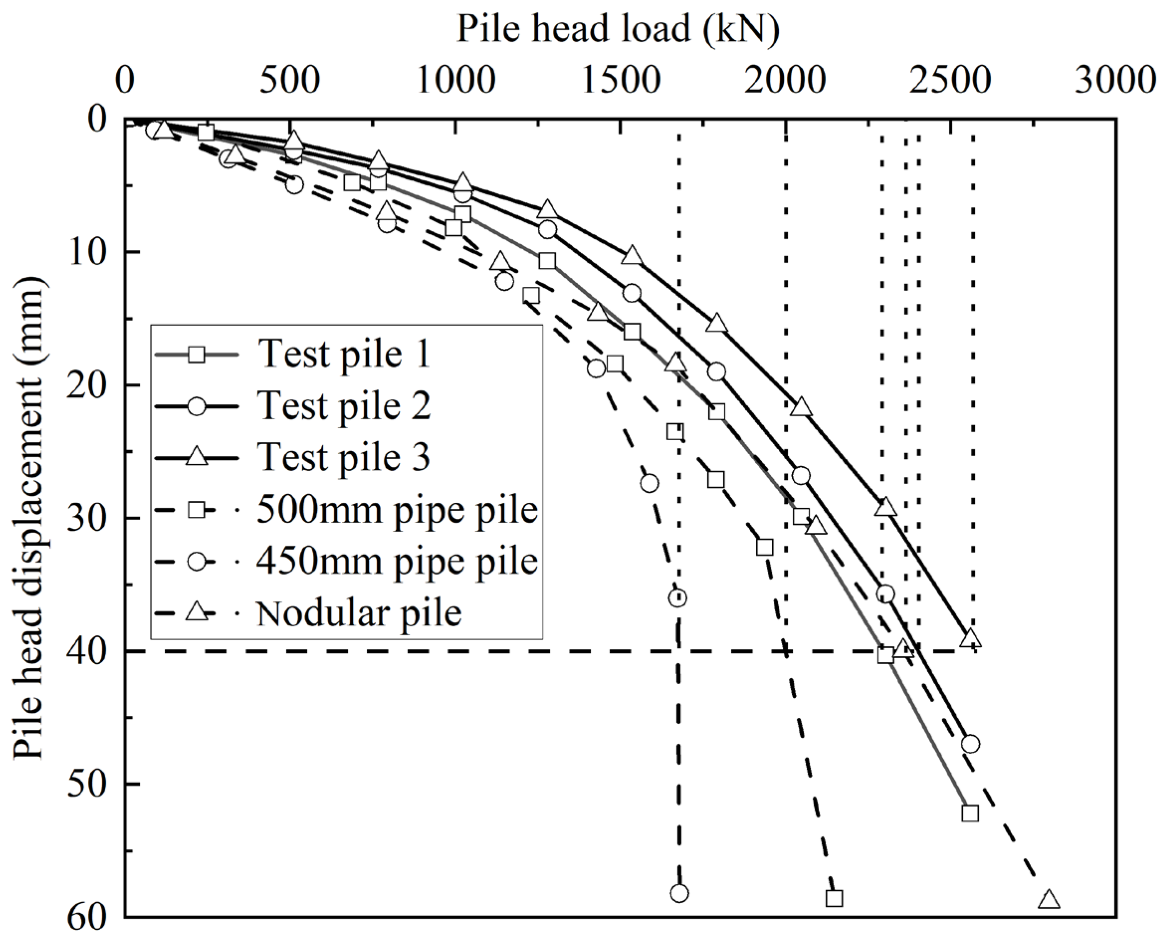
The measured pile head load and displacement of three test piles were then arranged as shown in
Figure 4. This figure shows that the load–displacement curve of three test piles were relatively close to each other. The pile head displacement increased linearly with pile head load when the applied load increased from 0 to 1024 kN. The pile head displacement of three test piles were all around 6 mm when loaded to 1024 kN. The displacement then increased with a larger increasing rate when the applied load increased from 1024 kN to 2564 kN. When the applied load reached 2564 kN, the displacement of three test PHC nodular piles reached 52.2 mm, 47 mm and 39.2 mm, respectively. The pile head load is normally considered as the ultimate capacity when the pile head displacement reaches 40 mm [
20]. The ultimate bearing capacity of three test piles were 2296 kN, 2401 kN and 2582 kN, respectively, and corresponding pile head displacement reached 40 mm.
The recommended ultimate skin friction and unit base resistance for driven PHC pipe piles are presented in
Table 1. The calculated shaft resistance of the 450 mm driven pipe pile was 1587 kN when the pile length was 40 m, and the calculated base resistance of closed-ended 450 mm driven pipe pile was 254 kN as the pile base was located in the clay layer. Hence, the calculated ultimate bearing capacity of the driven PHC pipe pile with a diameter of 450 mm and a length of 40 m was 1841 kN. The measured ultimate bearing capacity of three test piles were 1.25, 1.30 and 1.40 times of the calculated ultimate bearing capacity of the 450 mm PHC pipe pile, respectively. The previous research revealed that the shaft resistance of the 350 (400) mm PHC nodular pile was about 1.17–1.18 times of the 350 mm PHC pipe pile [
1]. The present research also demonstrated that the bearing capacity of the 450 (500) mm PHC nodular pile was better than that of the 450 mm PHC pipe pile. Moreover, the static load tests were conducted 30 days after pile installation in the previous research, and the measured shaft resistance of nodular pile was about 1.17–1.18 times of the pipe pile. In this research, the field tests were conducted 40 days after pile installation, and the measured ultimate bearing capacity of the 450 (500) mm PHC nodular pile was 1.25–1.40 times that of the 450 mm PHC pipe pile. It can be considered that the increasing rate of ultimate capacity of the PHC nodular pile was larger than that of the PHC pipe pile when the curing time increased from 30 to 40 days.
Elsherbiny and El Naggar [
6] indicated that for the helical pile embedded in clayey soil, the diameter of helix could be considered as the diameter of the helical pile when the helix spacing/helix diameter was less than 3.0. In this research, the 450 (500) mm PHC nodular pile was adopted, and nodular spacing and nodular diameter were 1000 mm and 500 mm, respectively. The ratio of nodular spacing/nodular diameter of the 450 (500) mm PHC nodular pile was 2.0, and the nodular diameter (500 mm) was then taken as the PHC nodular pile diameter to estimate its ultimate bearing capacity. The calculated ultimate shaft and base resistance were 1763 kN and 314 kN, respectively, for the driven PHC pipe pile with a diameter of 500 mm and a length of 40 m. The calculated ultimate bearing capacity of the PHC nodular pile was 2077 kN when the nodular diameter was used as the pile diameter. The ratio of measured/calculated ultimate bearing capacity of the three test PHC nodular piles were 1.11, 1.16 and 1.24 times, respectively. Hence, the measured ultimate bearing capacity of the 450 (500) mm PHC nodular pile was close to the calculated ultimate bearing capacity of the 500 mm PHC pipe pile. In the design of the PHC nodular pile embedded in clayey soil, the nodular diameter can be taken as the pile diameter to estimate its ultimate bearing capacity.
5. Analysis on Bearing Capacity of PHC Nodular Pile
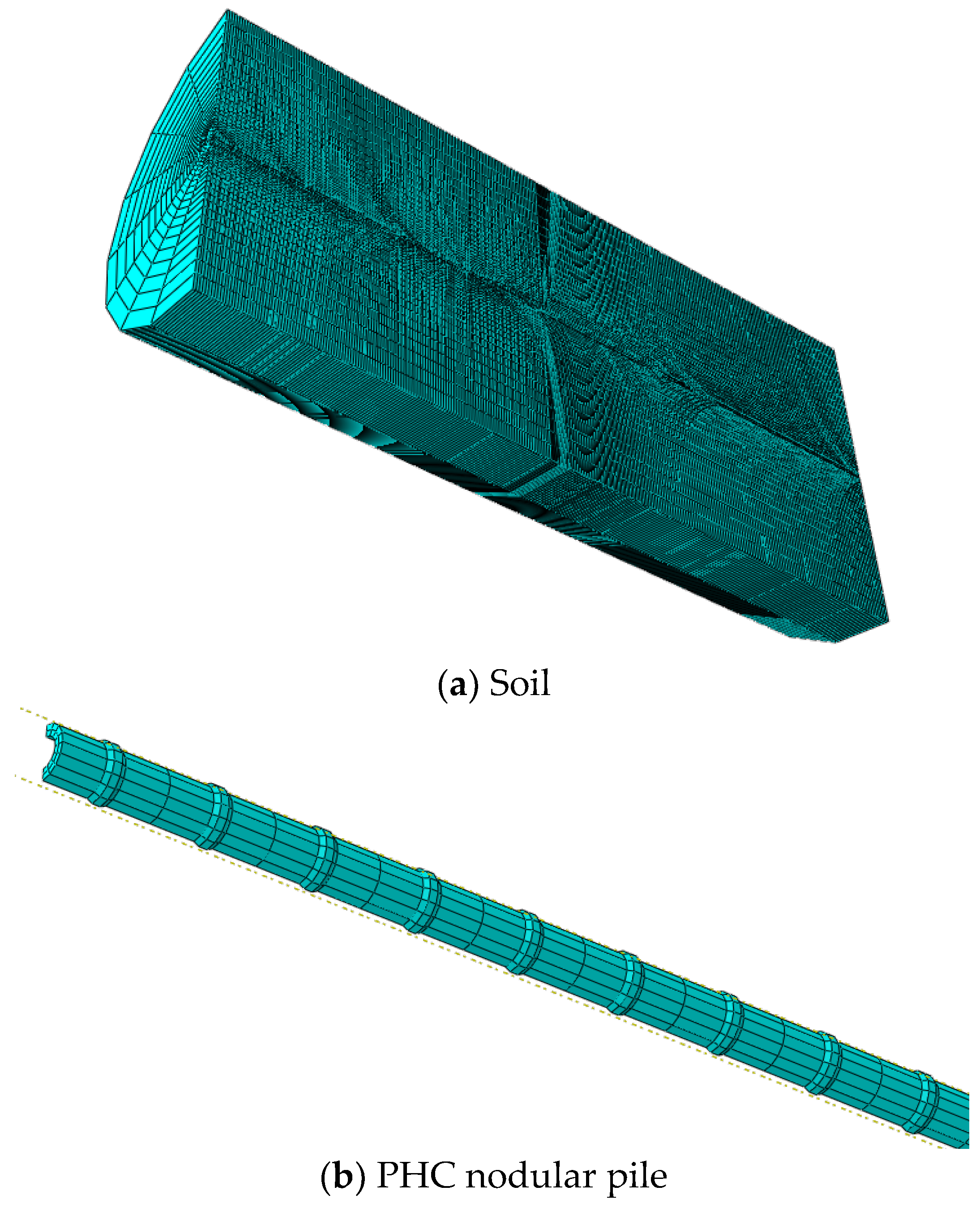
The 350 (400) mm, 450 (500) mm and 550 (600) mm PHC nodular piles are normally used in engineering projects, and the nodular spacing is 1 m. To investigate the effect of nodular parameters on the bearing capacity of PHC nodular pile, the ABAQUS was then adopted to build a PHC nodular pile model with different nodular spacing, nodular length and nodular diameter, as shown in
Table 3.
5.1. Effect of Nodular Spacing
The nodular spacing of the PHC nodular pile S was set as 1 m, 1.8 m, 2.6 m, 3.4 m and 4.2 m, respectively, in the modeling, and the calculated load–displacement responses of PHC nodular pile with different nodular spacing were arranged as shown in
Figure 7. It can be seen in
Figure 7 that the bearing capacity of the 450 (500) mm PHC nodular pile with a nodular spacing of 1 m and 1.8 m was better than the bearing capacity of 500 mm PHC pipe pile. When the pile head displacement reached 40 mm, the ultimate bearing capacity of the 450 (500) mm PHC nodular pile with a nodular spacing of 1 m and 1.8 m were 2357 kN and 2109 kN, respectively, which were larger than the ultimate bearing capacity of 500 mm PHC pipe pile. Nevertheless, when the nodular spacing increased to 2.6 m, the ultimate bearing capacity of the 450 (500) mm PHC nodular pile decreased to 1843 kN, which was smaller than the ultimate bearing capacity of the 500 mm PHC pipe pile. When the nodular spacing increased to 3.4 m and 4.2 m, the ultimate capacity decreased to 1688 kN and 1678 kN, respectively, which was close to the ultimate bearing capacity of the 450 mm PHC pipe pile.
According to the analysis above, the bearing capacity of the PHC nodular pile would decrease with nodular spacing. When the nodular spacing was 1.0 m and 1.8 m, the ultimate bearing capacities of the 450 (500) mm PHC nodular pile were 1.18 and 1.05 times that of the 500 mm PHC pipe pile. When the nodular spacing increased to 2.6 m, the ultimate bearing capacity of the 450 (500) mm PHC nodular pile was 0.92 times of the ultimate bearing capacity of the 500 mm PHC pipe pile, while ultimate bearing capacity of the 450 (500) mm PHC nodular pile was 1.1 times of the ultimate bearing capacity of the 450 mm PHC pipe pile. Hence, the nodules could still increase the bearing capacity of the pile when the nodular spacing reached 2.6 m. It should be noted that when the nodular spacing increased to 3.4 m and 4.2 m, the ultimate capacity of the 450 (500) mm PHC nodular pile was close to the ultimate capacity of the 450 mm PHC pipe pile, which indicated that the nodules could not improve the pile capacity. For the design of the PHC nodular pile in engineering projects, the nodular spacing should be smaller than 1.8 m to fully mobilize the bearing capacity of the PHC nodular pile.
5.2. Effect of Nodular Length
Two typical types of the PHC nodular piles (named as type A and type B) are normally used in engineering projects, as shown in
Figure 8. For type A PHC nodular pile, the diameter/length ratio of nodule is relatively large, as shown in
Figure 8a. For type B PHC nodular pile, the nodule length is large, and the diameter/length ratio is relatively small, as shown in
Figure 8b.
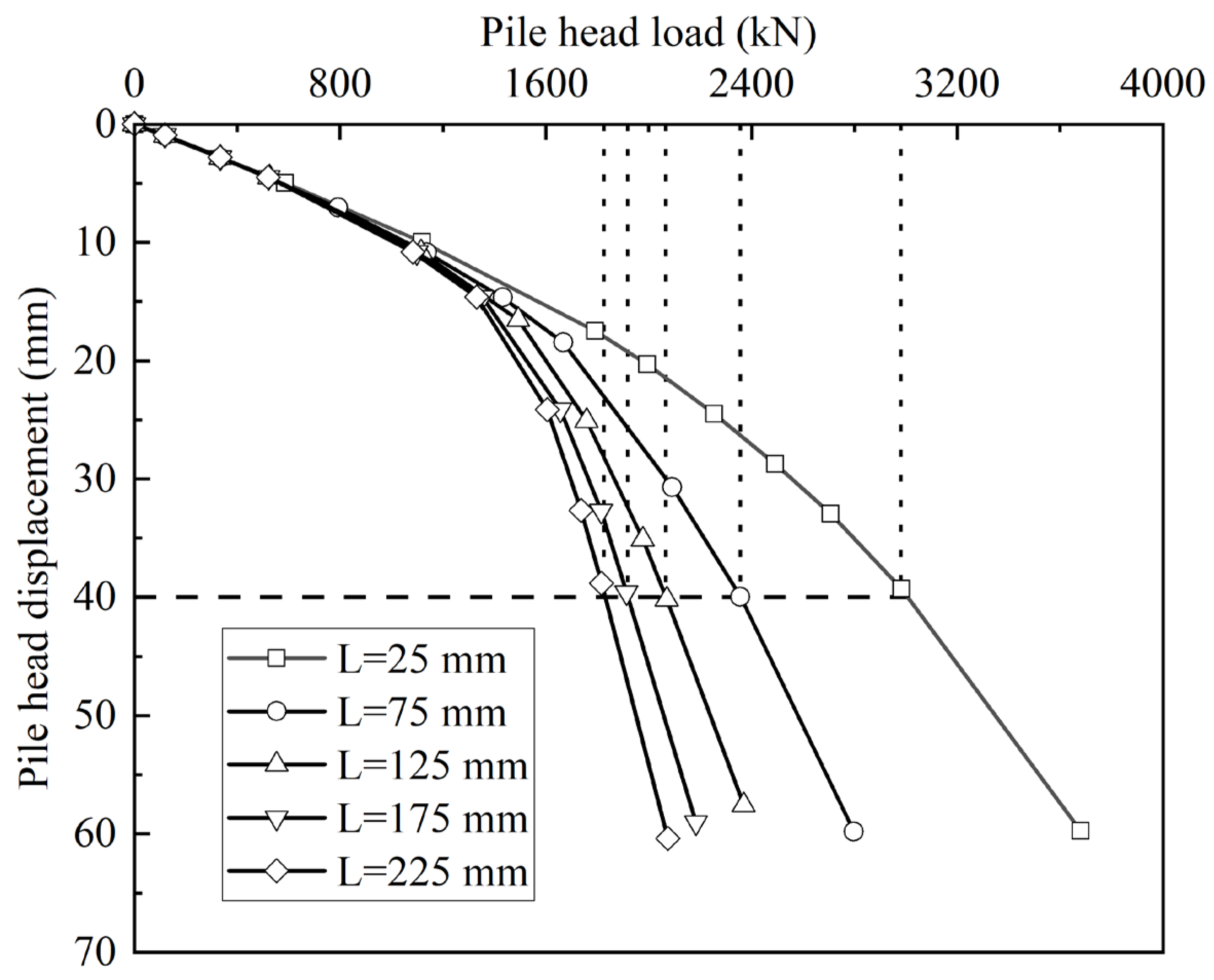
To investigate the influence of nodular length on the bearing capacity of the PHC nodular pile, the nodular length L was designed as 25 mm, 75 mm, 125 mm, 175 mm and 225 mm, respectively. The calculated load–displacement responses of the PHC nodular pile with different nodular lengths are arranged as shown in
Figure 9. It can be seen in
Figure 9 that the bearing capacity of the PHC nodular pile would decrease with the increase in nodular length, and the pile head displacement of the PHC nodular pile with different nodular length all increased stably with the pile head load. When the pile head displacement reached 40 mm, the ultimate bearing capacity of the PHC nodular piles were 2984 kN, 2357 kN, 2067 kN, 1920 kN and 1827 kN, respectively, as the nodular length increased from 25 mm to 225 mm. The ultimate bearing capacity of the PHC nodular pile decreased by 39% as the nodular length increased from 25 mm to 225 mm. Hence, the increase in nodular length would hamper the bearing capacity of the PHC nodular pile, and the type A PHC nodular pile was more suitable to improve pile capacity.
5.3. Effect of Nodular Diameter
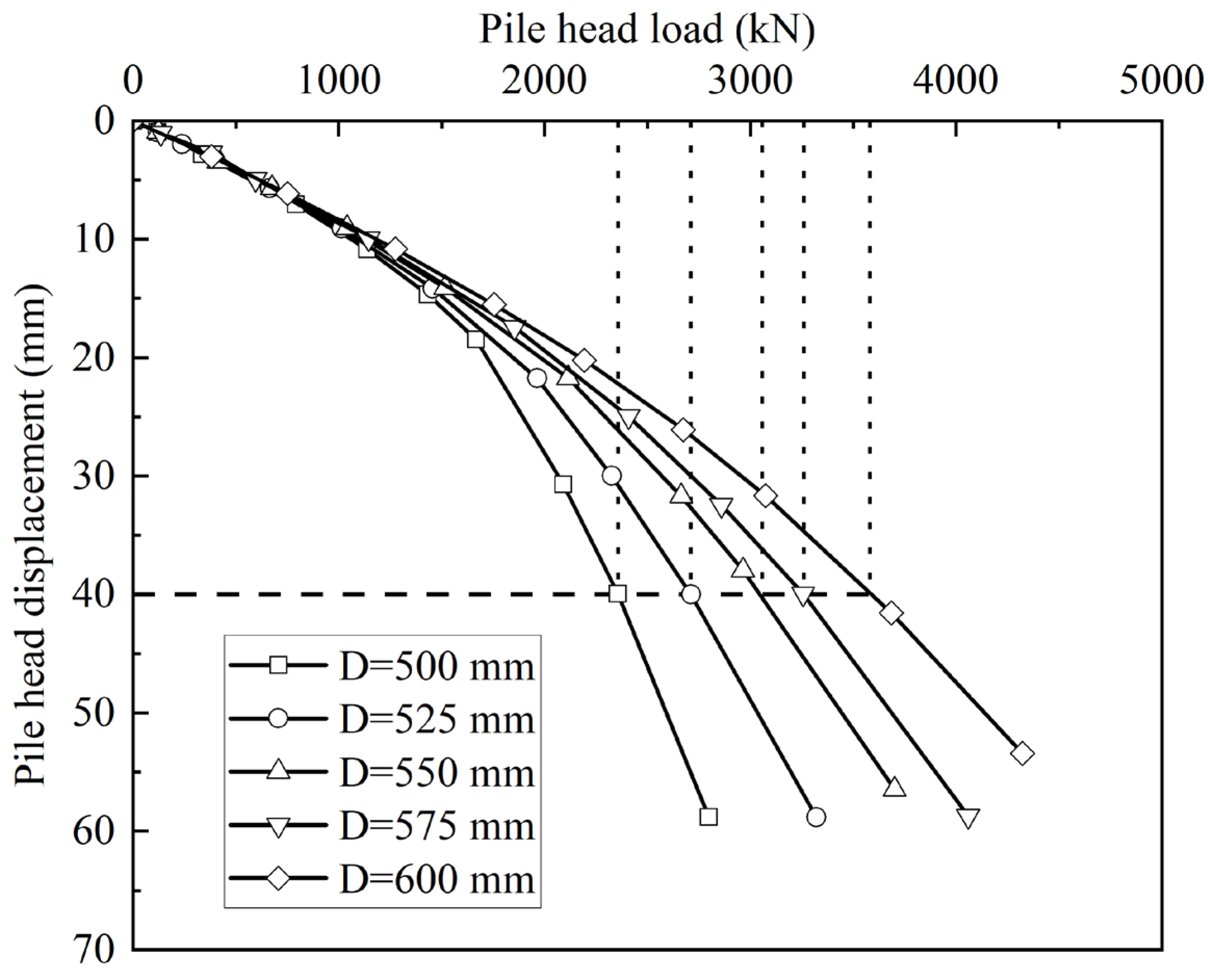
To investigate the influence of nodular diameter on the bearing capacity of the PHC nodular pile, the diameter of PHC nodular pile D was set to be 500 mm, 525 mm, 550 mm, 575 mm and 600 mm, respectively, and the diameter of pile shaft was set to be 450 mm. The simulated load–displacement responses of the PHC nodular pile with different nodular diameter are arranged as shown in
Figure 10.
It can be seen in
Figure 10 that the pile head displacements of the PHC nodular pile with different nodular diameters all increased stably with the pile head load, and no plunging failure occurred because of the exitance of nodules along the pile shaft. It can also be seen in
Figure 10 that the bearing capacity of the PHC nodular pile would increase with the increase in nodular diameter, and the ultimate capacities were 2359 kN, 2711 kN, 3049 kN, 3261 kN and 3583 kN, respectively, as the nodular diameter increased from 500 mm to 600 mm. The ultimate bearing capacity of the 450 (600) mm PHC nodular pile was 1.5 times the ultimate bearing capacity of the 450 (500) mm PHC nodular pile. Hence, the increase in nodular diameter could largely improve the bearing capacity of the PHC nodular pile. Nevertheless, it should be noted that the increase in nodular diameter would also increase the disturbance to the surrounding soil in the pile installation process, and the time needed for the recovery of soil strength after pile installation would also increase. The time needed for the recovery of soil strength after pile installation and the ultimate bearing capacity of PHC nodular pile after the recovery of soil strength should be comprehensively considered for the design of the driven PHC nodular pile in engineering projects.
5.4. Effect of Inclination Angle of Nodule
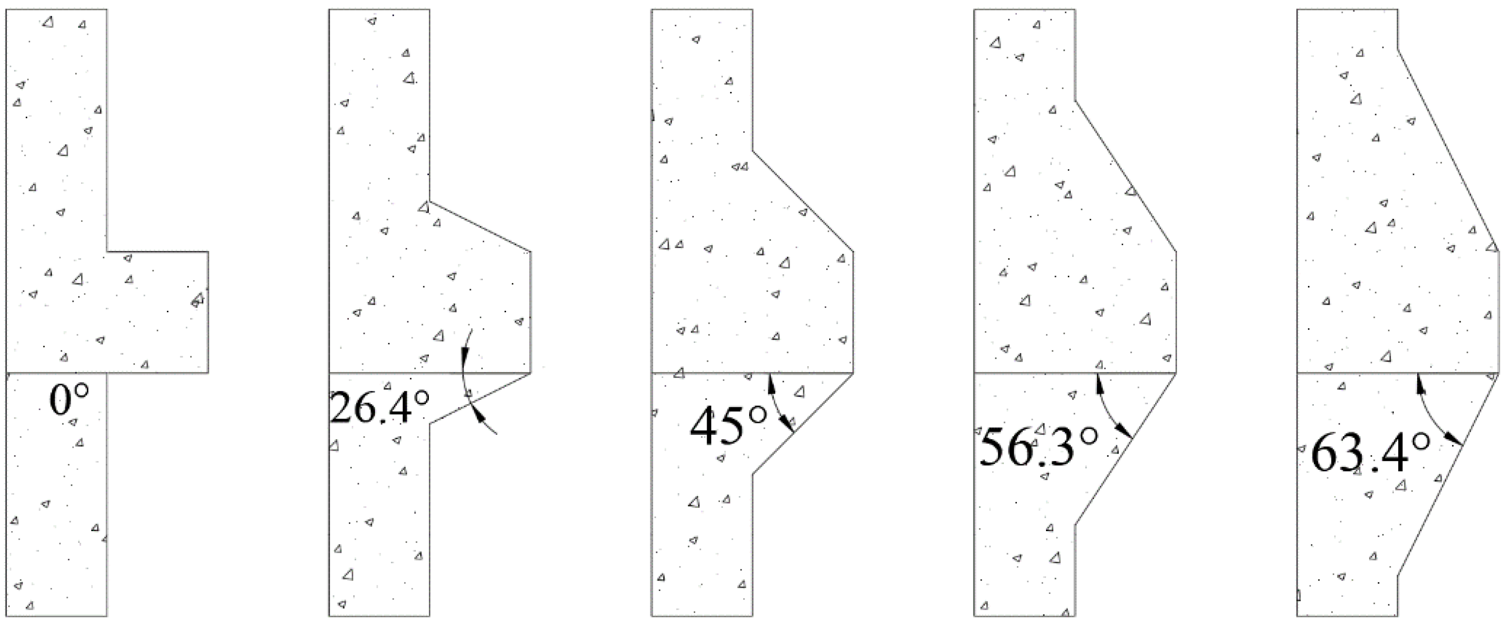
Apart from the nodular diameter and nodular length, the inclination angle of the nodule will also affect the bearing capacity of the PHC nodular pile. The tangent value of the inclination angle of nodule (tan
α) was set as 0, 0.5, 1, 1.5, and 2 (
α = 0°, 26.6°, 45°, 56.3°, and 63.4°), respectively, as presented in
Figure 11. The calculated load–displacement responses of the PHC nodular pile with different inclination angles are arranged as shown in
Figure 12.
Figure 12 shows that the pile head displacements of the PHC nodular pile with different inclination angles all increased stably with pile head load, and the ultimate bearing capacity of the PHC nodular pile decreased with the increase in inclination angle of nodule. The ultimate bearing capacities of the PHC nodular pile were 3186 kN, 2882 kN, 2719 kN, 2467 kN and 2357 kN, respectively, as the value of tan
α increased from 0 to 2. However, it should also be noted that the disturbance induced by pile installation would increase with the decrease in the inclination angle of the nodule. When the inclination angle of the nodule was 90°, the PHC nodular pile would become a PHC pipe pile. When the inclination angle of nodule decreased to 0°, the inclination angle of nodule would become a right angle and the installation effect of the PHC nodular pile would become the largest.
The nodular spacing, nodular length, nodular diameter and inclination angle of nodule will not only affect the bearing capacity of the PHC nodular pile, but also change the degree and extent of the installation effect. In the design of the driven PHC nodular pile in engineering projects, the relationship between the disturbance induced by pile installation and the ultimate bearing capacity of the PHC nodular pile after the recovery of soil strength should be comprehensively considered to select the appropriate value of nodular diameter.


