Article

Research on the Influence of Rectifying Orifice Plate on the Airflow Uniformity of Exhaust Hood

1
School of Civil and Resources Engineering, University of Science and Technology Beijing, Beijing 100083, China
2
China Academy of Safety Science and Technology, Beijing 100012, China
*
Author to whom correspondence should be addressed.
Appl. Sci. 2024, 14(21), 9917; https://doi.org/10.3390/app14219917
Submission received: 20 September 2024 / Revised: 23 October 2024 / Accepted: 25 October 2024 / Published: 30 October 2024
(This article belongs to the Special Issue Advances in Fluid Dynamics and Building Ventilation)

Abstract

:
Designing and improving collection systems for dust and toxic pollutants is crucial for improving the safety and indoor air quality of laboratory buildings. Push–pull ventilation systems with uniformly distributed parallel airflow have been proven to be of great help in this task. Designing exhaust hoods with parallel airflow distribution can effectively enhance the airflow uniformity of push–pull ventilation systems, especially when combining it with the implementation of rectifying orifice plates on the exhaust hoods. Therefore, this study combines a computational fluid dynamics (CFD) method and experimental approach to analyze the influence of key factors that lead to improvements in the airflow uniformity through the use of rectifying orifice plates, namely the aperture and porosity, as well as the number of rectifying orifice plates on the airflow uniformity of exhaust hoods. The study shows the following: (1) The aperture of the rectifying orifice plate considerably affects the airflow uniformity of the exhaust hood. Specifically, near the exhaust hood outlet, the airflow uniformity is negatively correlated with the aperture; conversely, near the exhaust hood inlet, the airflow uniformity is positively correlated with the aperture. (2) A rectifying orifice plate with a porosity of 35.43% can effectively improve the airflow uniformity of the exhaust hood. (3) Exhaust hoods with a double-layer rectifying orifice plate structure can improve airflow uniformity by approximately 40% compared to those with a single-layer structure. The above research results can guide the optimization of exhaust hood design to improve airflow uniformity, thereby effectively enhancing the capture efficiency of the push–pull ventilation system for dust and toxic pollutants and providing a safer environment for experimenters in laboratory buildings.

1. Introduction

Due to safety and indoor air quality requirements, laboratory buildings usually need to have local ventilation facilities. The push–pull ventilation system, a method of local ventilation, can effectively improve air quality and provide a safe environment for experimenters by capturing dust and toxic pollutants generated within the laboratory. This system consists of two main components: the air supply hood and the exhaust hood [1]. Research has demonstrated that an exhaust hood with parallel distributed uniform airflow can enhance the capture efficiency of dust and toxic pollutants [2]. Consequently, the study of parallel-flow push–pull ventilation systems is becoming increasingly crucial. Over time, parallel-flow push–pull ventilation systems have proven to be endowed with the advantages of effectively capturing dust and toxic pollutants [3,4,5,6,7]. As such, this type of ventilation system is being adopted more widely at present. To improve the parallel-flow push–pull ventilation system, one promising approach that has yet to be explored is to design parallel-flow exhaust hood that promotes airflow uniformity.
A large number of scholars have conducted research on the principle of the uniform airflow of exhaust hoods. The research shows the geometry of exhaust hoods, such as their flange size, pulling channel size, offset distance, etc., greatly affect the airflow characteristics [8]. For example, Chen et al. found that the airflow uniformity of the exhaust hood significantly influences the effectiveness of capturing pollutants, in a study of the effect of variations in wind velocity [9] and the size [10] of the exhaust hood using the dimensionless method. In another experiment, Wu et al. improved the airflow uniformity of the exhaust hood by optimizing the exhaust hood elbow [11]. Meanwhile, Wang et al. studied the effect of wind velocity uniformity on the mixing characteristics of push–pull ventilation systems [12] and carried out a series of experiments on the parallel-flow outlet with a double-layer rectifying orifice and a honeycomb push–pull ventilation system [13]. Research conducted by Chen et al. used CAD to establish four exhaust hood models with different structures and used Fluent (2014) to simulate and study the method of generating uniform airflow at the exhaust hood [5]. Finally, Cao et al. studied the push–pull ventilation system with a double-layer rectifying orifice plate in different parameters and concluded that the double-layer rectifying orifice plate structure leads to a better capture efficiency of dust and toxic pollutants than the single-layer rectifying orifice plate structure, but they did not analyze in detail how the rectifying orifice plate should be selected [14]. From this body of work, it clearly appears that setting up a rectifying orifice plate is an effective measure to improve the airflow uniformity of the exhaust hood. Typically, two parameters are considered in the design of a rectifying orifice plate: the aperture size of the holes (abbreviated as aperture here) and the porosity of the plate (abbreviated as porosity here) of the rectifying orifice plate. However, despite the wide adoption of this solution, the influence of the parameters of rectifying orifice plates on the airflow uniformity of exhaust hoods has not been clearly analyzed or characterized. This matter, i.e., the influence of different parameters of the rectifying orifice plate of the exhaust hood on the airflow uniformity, should be promptly addressed.
The use of computational fluid dynamics (CFD) methods to conduct research on push–pull ventilation systems has been demonstrated in numerous studies to be both a rational and efficient approach [2,8,9,10]. More recently, this computational method has also been broadened to simulate and analyze the effects of the rectifying orifice plate on the exhaust hood [5,12]. It has previously been shown that wind velocity non-uniformity is a key factor in evaluating the airflow uniformity of exhaust hoods [11,15,16]. In this study, we employed a CFD approach using Fluent to simulate and analyze the effects of the two parameters of the rectifying orifice plate on the airflow uniformity of the exhaust hood. Our goal was to construct a model of an exhaust hood equipped with a double-layer rectifying orifice plate that achieves optimal airflow uniformity with the lowest wind velocity non-uniformity by adjusting the aforementioned parameters. Finally, we conducted experimental measurements to verify the validity of the design and computational method.

2. Materials and Methods

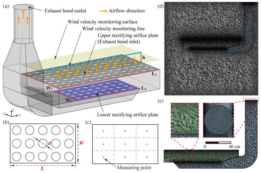
2.1. Model Establishment, Evaluation Method, and Mesh

Using CAD, we developed a 1:1 three-dimensional model of the exhaust hood in the push–pull ventilation system, based on similar theoretical foundations [17], to ensure meaningful comparisons between the systems are possible. As shown in Figure 1a, the characteristics of the exhaust hood are described as follows: the exhaust hood inlet length is 1200 mm, the width is 650 mm, and the exhaust hood outlet pipe diameter is 200 mm. Since the upper rectifying orifice plate of the exhaust hood usually serves as a workbench [7,18], in order to prevent the upward diffusion of gasses containing dust and toxic pollutants from being inhaled by the experimenter, the airflow direction of the exhaust hood is from the inlet to the outlet of the exhaust hood, as indicated by the yellow arrow. The exhaust hood includes two rectifying orifice plates: the upper rectifying orifice plate is located at the inlet of the exhaust hood, with dimensions of L1 = 1200 mm and W1 = 650 mm. Meanwhile, the lower one is located inside the exhaust hood, with dimensions of L2 = 750 mm and W2 = 410 mm. For a rectifying orifice plate, the main factors affecting the airflow uniformity are the aperture (denoted by d), the porosity (denoted by α), and the number of rectifying orifice plates. Figure 1b shows the two parameters of the rectifying orifice plate, aperture and porosity. The aperture refers to the diameter of each hole on the rectifying orifice plate, and the porosity is the ratio of the total area of the holes to the area of the plate itself. For a rectifying orifice plate with a length of L and a width of W, and assuming that the number of holes on the rectifying orifice plate is m, then porosity α can be calculated using the following Equation (1):
α = Total   area   of   holes Area   of   the   plate = m π d 2 2 L · W ,
Typically, the apertures range from 2 mm to 6 mm, and the porosity ranges from 4.91% to 62.98%. In this study, rectifying orifice plates with designated apertures of 2, 3, 4, 5, and 6 mm and porosities of 4.91%, 17.91%, 35.43%, 47.79%, and 62.98% are selected. Therefore, we studied the cases of single-layer and double-layer rectifying orifice plates with different apertures and porosities to determine which structure and characteristics yield the best rectifying effect. Since the upper rectifying orifice plate is used as a workbench [19], the area above the upper rectifying orifice plate is where dust and toxic pollutants are generated. Therefore, the wind velocity monitoring surface (parallel to the xy plane) and line (parallel to the x-axis) is set as shown in Figure 1a for simulation analysis, with a height of h = 100 mm from the upper rectifying orifice plate. The average wind velocity and wind velocity non-uniformity at the monitoring surface are used to evaluate the influence of the rectifying orifice plate on the airflow uniformity of the exhaust hood [20]. As shown in Figure 1c, assuming that the number of measuring points on the monitoring surface is n, then the formula for calculating the wind velocity non-uniformity is reported as Equation (2).
β = v i v ¯ 2 n 1 v ¯ ,
where β is the wind velocity non-uniformity; v i is the measured wind velocity at the measuring point; v ¯ is the average wind velocity; and n is the number of measuring points.
To prevent the influence of the surrounding environment on the airflow uniformity of the exhaust hood, a cubic calculation domain with a side length of 2000 mm is selected. The overall mesh size of the computational domain and the exhaust hood model is 20 mm, as shown in Figure 1d. The mesh at the exhaust hood outlet and the two rectifying orifice plates of the model is built with a face size of 5 mm. In order to accurately analyze the flow field characteristics of the exhaust hood, a 4-layer boundary layer with an initial grid height of 1 mm and a growth rate of 1.1 is created, as shown in Figure 1e. The mesh quality is checked, and the orthogonality quality of the mesh is 0.78, which means that the mesh is of better quality.

2.2. Control Equations and Boundary Conditions

For the numerical simulation of the 3D model of the exhaust hood, a double precision 3D solver is used in order to improve the calculation accuracy. We employ the conventional k-ε double equation model, as it provides a respectable level of accuracy in engineering simulation computations [21]. In our simulation, while the momentum transfer is considered in the model, the thermal conductivity is neglected, so the energy equation is set to be closed. In order to fully calculate the flow field characteristics, the convergence standard is set to 10−6. The boundary at the outlet of the exhaust hood is set as a velocity inlet with a velocity of 13 m/s in the positive z-axis. The hydraulic diameter is the exhaust hood outlet diameter of 0.2 m. According to the empirical formula , the turbulence intensity can be calculated using the following formula:
I = 0.16 ( R e D H ) 1 / 8 ,
where R e D H is the Reynolds number of the exhaust hood outlet.
R e D H = ρ v l V ,
where
ρ—Air density, kg/m3 (1.225 kg/m3).
v—Wind velocity, m/s (13 m/s).
l —Hydraulic diameter, m (0.2 m).
V —Dynamic viscosity, Pa·s (1.7894 × 10⁻⁵ Pa·s).
The combined calculation of Equations (3) and (4) gives a turbulence intensity of 3.53%. The boundaries surrounding the computational domain are set as outflow to simulate an open laboratory space, while the top and bottom are set as walls to simulate the floor and roof of the laboratory. The model solving parameters and boundary conditions are shown in Table 1.

3. Results

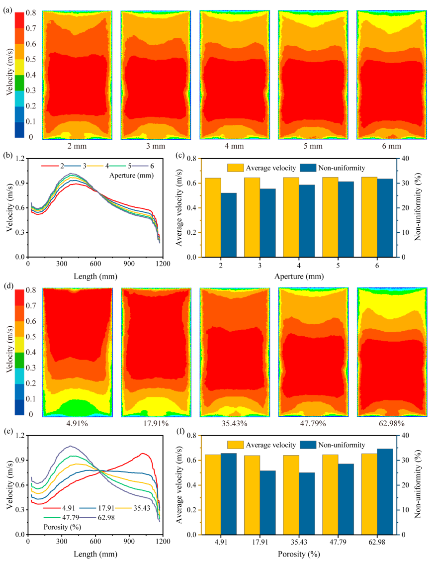
3.1. Influence of Single-Layer Rectifying Orifice Plate on the Airflow Uniformity of Exhaust Hood

In this part, we study the influence of the aperture and porosity of a single-layer rectifying orifice plate on the airflow uniformity of the exhaust hood. Figure 2 displays the wind velocity contours of the monitoring surface and the center axis wind velocity distribution along the monitoring line at the rectifying orifice plate with varying apertures and porosities. We initially analyze the lower rectifying orifice plates with the different apertures of d = 2, 3, 4, 5, and 6 mm under a condition of fixed porosity.
Figure 2a shows the wind velocity contour of the monitoring surface under varying apertures. It can be observed that as the aperture increases, the area of low wind velocity in the diagram significantly increases. Figure 2b presents the center axis wind velocity distribution along the monitoring line under different apertures. As the aperture increases, the maximum wind velocity appears around 400 mm of the exhaust hood and then begins to decrease. Notably, the curve for d = 2 mm exhibits a smaller difference between the maximum and minimum wind velocities, while the curve for d = 6 mm shows a larger disparity. Yet, the center axis wind velocity can only quantitatively analyze the airflow uniformity at the center of the exhaust hood. Therefore, we analyzed the average wind velocity and wind velocity non-uniformity of the monitoring surface as shown in Figure 2c. At d = 2 mm, the average wind velocity is 0.6418 m/s, and at d = 6 mm, it is 0.6496 m/s. Clearly, as the aperture increases, the average wind velocity slightly increases, but the aperture has almost no influence on the average wind velocity. However, the impact of the aperture on the wind velocity non-uniformity is very substantial. At d = 2 mm, the wind velocity non-uniformity is 26.01%, compared to 31.79% at d = 6 mm, indicating a decrease of 5.78%. We then further explored the influence of porosity α = 4.91%, 17.91%, 35.43%, 47.79%, and 62.98% under the optimal aperture d = 2 mm.
Figure 2d shows the wind velocity contour of the monitoring surface under different porosities. As the porosity increases, the area of low wind velocity initially decreases and then increases. Figure 2e presents the center axis wind velocity distribution along the monitoring line under different porosities. It is observed that as the porosity increases, the maximum wind velocity shifts from about 1000 mm to 400 mm of the exhaust hood. At α = 17.91%, the center axis wind velocity shows a relatively flat trend, indicating a more uniform distribution of the wind velocity at this condition. Interestingly, when calculating the average wind velocity and wind velocity non-uniformity of the monitoring surface, as shown in Figure 2f, it is found that, at α = 17.91%, the wind velocity non-uniformity is 25.81%, compared to 25.02% at α = 35.43%. This inconsistency with the conclusions drawn from the center axis wind velocity suggests that the center axis wind velocity does not fully represent the distribution of the airflow of the exhaust hood. Additionally, as the porosity increases, the average wind velocity initially decreases and then increases. When α = 17.91%, the minimum average wind velocity is 0.6377 m/s. Based on these findings, a rectifying orifice plate with d = 2 mm and α = 35.43% was chosen to achieve optimal airflow uniformity. This setup resulted in an average wind velocity of 0.6400 m/s and a wind velocity non-uniformity of 25.02%.

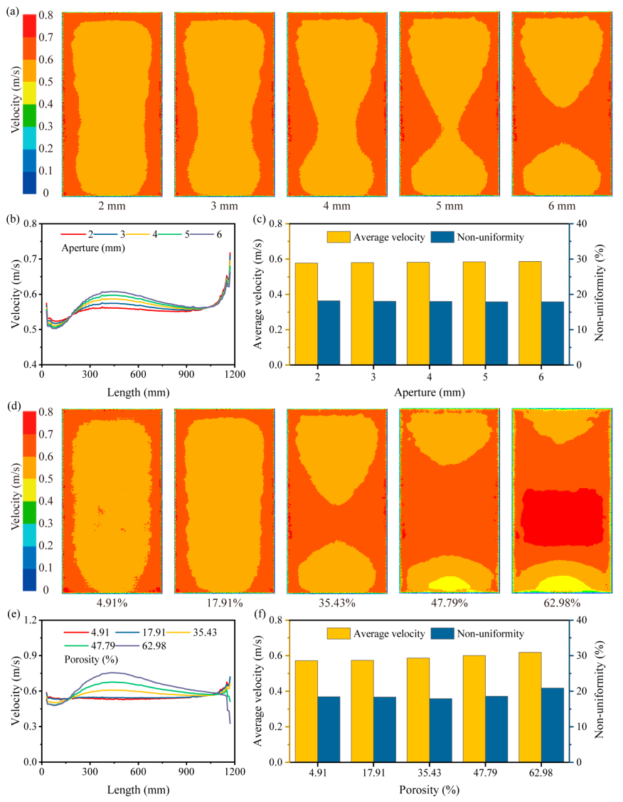
3.2. Influence of Double-Layer Rectifying Orifice Plate on the Airflow Uniformity of Exhaust Hood

For an exhaust hood with a double-layer rectifying orifice plate, the wind velocity non-uniformity is at least 25.02%. However, according to engineering practices, it is generally required to reduce the wind velocity non-uniformity to below 20% to significantly enhance the capture efficiency of dust and toxic pollutants by the exhaust hood. Therefore, to further improve the airflow uniformity of the exhaust hood, we propose using a double-layer rectifying orifice plate. Considering the previously mentioned results, the lower rectifying orifice plate was modeled with d = 2 mm and α = 35.43%. Initially, we examined an upper rectifying orifice plate with a fixed porosity of 35.43% and apertures of d = 2, 3, 4, 5, and 6 mm. The simulation results for the wind velocity contour and center axis wind velocity distribution for a double-layer rectifying orifice plate, considering various porosities and apertures, are shown in Figure 3.
Figure 3a displays the wind velocity contour of the monitoring surface under different apertures. It can be observed that when d = 2 mm, the central region of the monitoring surface has a slightly lower wind velocity compared to the edge areas; as the aperture increases, there is a slight increase in the wind velocity in the central region of the exhaust hood. Figure 3b shows the center axis wind velocity distribution along the monitoring line under different apertures. It is apparent that the center axis wind velocities are relatively consistent across different apertures, but the curve for d = 2 mm is the flattest, indicating more stable wind velocities under this condition. Further analysis of the average wind velocity and wind velocity non-uniformity of the monitoring surface is shown in Figure 3c. Through our calculation, we found that as the aperture increases, the average wind velocity slightly increases, from the lowest at d = 2 mm with 0.5771 m/s to 0.5863 m/s at d = 6 mm. Surprisingly, the wind velocity non-uniformity decreases with the increasing aperture, which contradicts our previous results. At d = 2 mm, the wind velocity non-uniformity is the highest, at 18.19%; at d = 6 mm, it is the lowest, at 17.92%. Consequently, we further analyzed the effect of the porosities α = 4.91%, 17.91%, 35.43%, 47.79%, and 62.98% under the optimal aperture d = 6 mm.
Figure 3d shows the wind velocity contour of the monitoring surface under different porosities. As the porosity increases, the low wind velocity area in the center of the exhaust hood continuously decreases. When the porosity reaches 62.98%, the wind velocity at the center is significantly higher than at the edges of the exhaust hood. Figure 3e shows the center axis wind velocity distribution along the monitoring line under different porosities. It is observed that as the porosity increases, the center axis wind velocity at 400 mm of the exhaust hood continually increases. The data from Figure 3f indicate that as the porosity increases, the average wind velocity also increases, from 0.5719 m/s at α = 4.91% to 0.6183 m/s at α = 62.98%. The wind velocity non-uniformity initially decreases and then increases as the porosity increases, reaching its lowest at 17.92% when α = 35.43%. Integrating these findings, using an upper rectifying orifice plate with d = 6 mm and α = 35.43% provides optimal airflow uniformity for the exhaust hood, with an average wind velocity of 0.5863 m/s and a wind velocity non-uniformity of 17.92%.

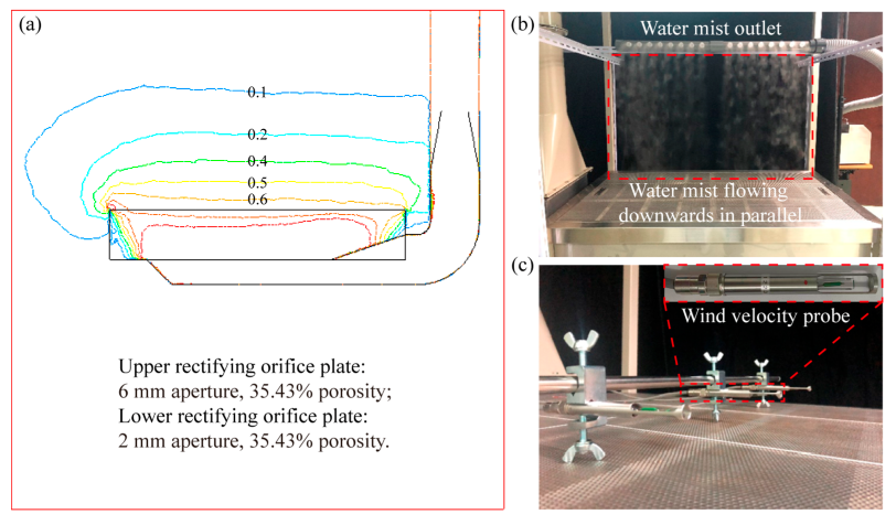
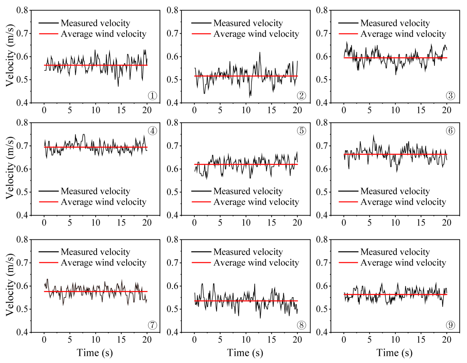
4. Experiment and Discussion

The simulation analysis of the single-layer and double-layer rectifying orifice plates reveals that the two parameters, aperture and porosity, crucially affect the airflow uniformity of the exhaust hood. Firstly, we found varying the apertures of the rectifying orifice plate from 2 mm to 6 mm considerably affects the airflow uniformity of the exhaust hood. Our results indicate that near the exhaust hood outlet, the airflow uniformity is negatively correlated with the aperture; conversely, near the exhaust hood inlet, the airflow uniformity is positively correlated with the aperture. Additionally, the impact of the aperture on the wind velocity non-uniformity is more pronounced in the rectifying orifice plate located near the exhaust hood outlet. The average wind velocity of the exhaust hood increases with the aperture.
Regarding the influence of the porosity on the airflow uniformity, we achieved the best results with a porosity of 35.43%. It is noteworthy that using a higher porosity for the lower layer than for the upper layer in the double-layer rectifying orifice plate causes noticeable wind velocity fluctuations, as shown in Figure 3d. Indeed, under certain conditions of wind velocity, the porosity of the rectifying orifice plate affects the total airflow volume through a given section per unit time. Thus, when the porosity of the upper layer of the rectifying orifice plate is too small, the total airflow volume through the section reduces, which generates a vortex at the section that provokes the fluctuation of the wind velocity. Moreover, when the porosity of the upper rectifying orifice plate is set to 62.98%, the airflow uniformity of the exhaust hood is impaired.
Additionally, exhaust hoods with double-layer rectifying orifice plates exhibit better wind velocity non-uniformity than those with single-layer plates, demonstrating that rectifying orifice plates effectively enhance airflow uniformity. Therefore, a model of the exhaust hood with a double-layer rectifying orifice plate was constructed, featuring an upper rectifying orifice plate with an aperture of 6 mm and a porosity of 35.43% and a lower rectifying orifice plate with an aperture of 2 mm and the same porosity. Figure 4a shows the isopleth map of the wind velocity located vertically to the monitoring surface along the center line. It can be observed that the isopleths of the wind velocity ranging from 0.5 m/s to 0.1 m/s are essentially parallel to the surface of the exhaust hood, indicating that the airflow above the exhaust hood does not diffuse horizontally. The isopleth at 0.5 m/s is located approximately 100 mm above the exhaust hood, suggesting that the wind velocity near the exhaust hood exceeds 0.5 m/s, meeting the design specifications of the exhaust hood.
In order to verify that our simulation results accurately reflect the experimental device, we built an exhaust hood device with an upper rectifying orifice plate with aperture of 6 mm and a lower rectifying orifice plate with aperture of 2 mm, with a porosity of 35.43% for both plates, which were made using 2 mm thickness steel plates. The flow field within the exhaust hood was visualized by an artificially generated water mist. As shown in Figure 4b, to avoid interference caused by the initial velocity of the water mist, the mist outlet was arranged parallel to the surface of the exhaust hood. It can be observed that the horizontally released water mist was collected by the airflow and moved vertically downward, parallel to each other. This demonstrates that the airflow inside the exhaust hood was distributed in parallel, which confirms that the double-layer rectifying orifice plate structure provided excellent airflow uniformity.
To further quantify the airflow uniformity of the exhaust hood, a multi-channel anemometer (1560, Kanomax, Osaka, Japan) was used to measure the wind velocity at a distance of approximately 30 mm from the surface of the exhaust hood with a high-precision wind velocity probe (0963, Kanomax, Osaka, Japan), as depicted in Figure 4c. The surface of the exhaust hood was divided evenly into 9 areas, and the measuring points ① to ⑨ of the wind velocity was located at the center of each area, as shown in Figure 1c. Each measuring point was tested continuously for 20 s, and the measured velocity and average velocity were recorded and calculated, as shown in Figure 5.
The experiment demonstrates that the wind velocity fluctuated around the average wind velocity by about 0.1 m/s. Moreover, the average wind velocity at each measuring point exceeded 0.5 m/s. This result is consistent with our simulation results. Using the measured velocity obtained from the nine measuring points, the average wind velocity and the wind velocity non-uniformity of the exhaust hood were calculated according to Equation (2). The results indicated that the average wind velocity was 0.5917 m/s, more than 0.5 m/s [22], with a wind velocity non-uniformity of 9.84%, less than 25%. These experimental results are in good alignment with the simulation data. Our study demonstrates that rectifying orifice plates significantly affects the airflow uniformity of exhaust hoods. Specifically, the double-layer rectifying orifice plate configuration enables the airflow within the exhaust hood to be distributed in parallel, effectively enhancing the capture efficiency of dust and toxic pollutants.

5. Conclusions

Through analyzing the simulation and experimental results obtained from varying the apertures and porosities of the rectifying orifice plates, we evaluated their influence on the airflow uniformity and drew the following conclusions:
(1)
The average wind velocity of the exhaust hood generally increases with the increase in aperture and porosity of the rectifying orifice plate. The impact of the aperture on the airflow uniformity of the exhaust hood depends on the position of the plate. Near the exhaust hood outlet, the airflow uniformity is negatively correlated with the aperture; near the exhaust hood inlet, the airflow uniformity is positively correlated with the aperture. A rectifying orifice plate with a porosity of 35.43% can effectively improve the airflow uniformity of the exhaust hood.
(2)
Exhaust hoods with a double-layer rectifying orifice plate structure can improve airflow uniformity by approximately 40% compared to those with a single-layer structure. When designing exhaust hoods with more stringent requirements for airflow uniformity, a multi-layer rectifying orifice plate structure can be used to further enhance airflow uniformity.
The results of this study can guide the optimization of exhaust hood design and improve the airflow uniformity by setting appropriate rectifying orifice plates, thereby effectively enhancing the capture efficiency of the entire parallel-flow push–pull ventilation system for dust and toxic pollutants.

Author Contributions

Conceptualization: L.L. and C.D.; Data curation: L.L. and B.Y.; Formal analysis: L.L.; Funding acquisition: C.D.; Investigation: L.L.; Project administration: Y.W.; Resources: C.D.; Supervision: C.D.; Validation: L.L. and Y.W.; Writing—original draft: L.L.; Writing—review and editing: C.D., B.Y., and Y.W. All authors have read and agreed to the published version of the manuscript.

Funding

This research was funded by the National Key Research and Development Program of China (2022YFC2905003) and the fundamental research found for China Academy of Safety Science and Technology (2023JBKY21).

Institutional Review Board Statement

Not applicable.

Informed Consent Statement

Not applicable.

Data Availability Statement

The data presented in this study are available on request from the corresponding author.

Conflicts of Interest

The authors declare no conflicts of interest.

Nomenclature

SymbolPropertyUnits
L1Length of the upper rectifying orifice platemm
W1Width of the upper rectifying orifice platemm
L2Length of the lower rectifying orifice platemm
W2Width of the lower rectifying orifice platemm
dAperture of the rectifying orifice platemm
αOpening ratio of the rectifying orifice plate%
LLength of the rectifying orifice platemm
WWidth of the rectifying orifice platemm
mNumber of holes on the rectifying orifice plate/
hHeight from the upper rectifying orifice plate to the monitoring surface and linemm
nNumber of measuring points/
β Wind velocity non-uniformity%
v i Measured wind velocity at the measuring pointm/s
v ¯ Average wind velocitym/s

References

  1. Hughes, R.T. An Overview of Push—Pull Ventilation Characteristics. Appl. Occup. Environ. Hyg. 1990, 5, 156–161. [Google Scholar] [CrossRef]
  2. Ye, W.-B. Design Method and Modeling Verification for the Uniform Air Flow Distribution in the Duct Ventilation. Appl. Therm. Eng. 2017, 110, 573–583. [Google Scholar] [CrossRef]
  3. Huebener, D.J.; Hughes, R.T. Development of Push-Pull Ventilation. Am. Ind. Hyg. Assoc. J. 1985, 46, 262–267. [Google Scholar] [CrossRef]
  4. Wang, Y.; Quan, M.; Zhou, Y.; Cao, Y.; Xie, C.; Li, L. Experimental Study on the Flow Field and Economic Characteristics of Parallel Push-Pull Ventilation System. Energy Built Environ. 2020, 1, 393–403. [Google Scholar] [CrossRef]
  5. Chen, J.; Jin, L.; Yang, B.; Chen, Z.; Zhang, G. Influence of the Internal Structure Type of a Large-Area Lower Exhaust Workbench on Its Surface Air Distribution. Int. J. Environ. Res. Public Health 2022, 19, 11395. [Google Scholar] [CrossRef] [PubMed]
  6. Huang, R.F.; Lin, S.Y.; Jan, S.-Y.; Hsieh, R.H.; Chen, Y.-K.; Chen, C.-W.; Yeh, W.-Y.; Chang, C.-P.; Shih, T.-S.; Chen, C.-C. Aerodynamic Characteristics and Design Guidelines of Push–Pull Ventilation Systems. Ann. Occup. Hyg. 2005, 49, 1–15. [Google Scholar] [CrossRef]
  7. Liu, K.; Yang, S.; Zeng, L.; Gao, J.; Hou, Y.; Cao, C.; Shi, B.; Mo, X.; Zhang, Q.; Hou, C. Combining Push-Pull Airflow and Top Draft Hood for Local Exhaust of Tyre Vulcanization Process. Energy Built Environ. 2020, 1, 296–306. [Google Scholar] [CrossRef]
  8. Chern, M.-J.; Ma, C.-H. Numerical Investigation and Recommendations for Push-Pull Ventilation Systems. J. Occup. Environ. Hyg. 2007, 4, 184–197. [Google Scholar] [CrossRef]
  9. Chen, J.; Jin, L.; Chen, Z.; Yang, B.; Sun, Y.; Zhou, S. Center-Line Velocity Change Regime in a Parallel-Flow Square Exhaust Hood. Int. J. Environ. Res. Public Health 2020, 17, 4485. [Google Scholar] [CrossRef]
  10. Chen, J. Research on the Axial Velocity Change Rule of Desktop Slot Exhaust Hood. Ind. Health 2018, 56, 278–284. [Google Scholar] [CrossRef]
  11. Wu, X.; Liu, L.; Luo, X.; Chen, J.; Dai, J. Study on Flow Field Characteristics of the 90° Rectangular Elbow in the Exhaust Hood of a Uniform Push–Pull Ventilation Device. Int. J. Environ. Res. Public Health 2018, 15, 2884. [Google Scholar] [CrossRef] [PubMed]
  12. Wang, Y.; Quan, M.; Zhou, Y. Effect of Velocity Non-Uniformity of Supply Air on the Mixing Characteristics of Push-Pull Ventilation Systems. Energy 2019, 187, 115962. [Google Scholar] [CrossRef]
  13. Wang, Y.; Huang, Y.; Zhou, Y.; Shu, Y.; Liu, J. Experimental Study on One-Side Confined Jets from a Parallel-Flow Outlet in a Push–Pull Ventilation System. Indoor Built Environ. 2015, 24, 73–86. [Google Scholar] [CrossRef]
  14. Cao, Y.; Wang, Y.; Li, C.; Ding, J.; Yang, Y.; Ren, X. A Field Measurement Study of a Parallel-Flow Push–Pull System for Industrial Ventilation Applications. Int. J. Vent. 2016, 15, 167–181. [Google Scholar] [CrossRef]
  15. Zhang, J.; Wang, J.; Gao, J.; Cao, C.; Lv, L.; Xie, M.; Zeng, L. Critical Velocity of Active Air Jet Required to Enhance Free Opening Rectangular Exhaust Hood. Energy Build. 2020, 225, 110316. [Google Scholar] [CrossRef]
  16. Yan, H.; Li, X.; Fu, Z.; Bai, Z.; Zhang, H. Uniform Exhaust Characteristics of New-Type Airbox Components of Continuous Miner. Trans. Can. Soc. Mech. Eng. 2023, 47, 388–397. [Google Scholar] [CrossRef]
  17. Jiang, W.; Xu, X.; Wen, Z.; Wei, L. Applying the Similarity Theory to Model Dust Dispersion during Coal-Mine Tunneling. Process Saf. Environ. Prot. 2021, 148, 415–427. [Google Scholar] [CrossRef]
  18. Muta, R.; Chung, J.; Li, C.; Yoo, S.-J.; Ito, K. Pollutant Capture Efficiencies in and around the Opening Surface of a Fume Hood under Realistic Conditions. Indoor Built Environ. 2022, 31, 1636–1653. [Google Scholar] [CrossRef]
  19. Cao, Z.; Zhou, Y.; Cao, S.; Wang, Y. Chapter 2—Local Ventilation. In Industrial Ventilation Design Guidebook, 2nd ed.; Goodfellow, H.D., Wang, Y., Eds.; Academic Press: Cambridge, MA, USA, 2021; pp. 7–108. ISBN 978-0-12-816673-4. [Google Scholar]
  20. Deng, Q.; Liu, H.; He, Y.; Huang, T.; Zhou, H.; Bao, Y. Uniformity and Energy Evaluation of Equal Cross-Section Ventilation System(ECVS) for Long Tunnel in Underground Buildings. Energy Built Environ. 2022, 3, 86–94. [Google Scholar] [CrossRef]
  21. Zaïdi, H.; Fohanno, S.; Taïar, R.; Polidori, G. Turbulence Model Choice for the Calculation of Drag Forces When Using the CFD Method. J. Biomech. 2010, 43, 405–411. [Google Scholar] [CrossRef]
  22. Muta, R.; Ito, K. Impact of Heat Generation and Use of Experimental Instruments in a Fume Hood on Pollutant Capture Efficiency. Jpn. Archit. Rev. 2022, 5, 702–713. [Google Scholar] [CrossRef]
Figure 1. (a) Exhaust hood with double-layer rectifying orifice plate; (b) parameters of the rectifying orifice plate; (c) measuring points illustration; (d) overall mesh of the computational domain and the exhaust hood model; (e) exhaust hood mesh and face mesh at the exhaust hood outlet and the two rectifying orifice plates.
Applsci 14 09917 g001
Figure 2. The influence of the single-layer rectifying orifice plate on the airflow uniformity. (a) Wind velocity contour of the monitoring surface under different d; (b) center axis wind velocity distribution of the monitoring line under different d; (c) histogram compares the average wind velocity and wind velocity non-uniformity of the monitoring surface under different d; (d) wind velocity contour of the monitoring surface under different α; (e) center axis wind velocity distribution of the monitoring line under different α; (f) average wind velocity and wind velocity non-uniformity of the monitoring surface under different α.
Applsci 14 09917 g002
Figure 3. The influence of a double-layer rectifying orifice plate on the airflow uniformity. (a) Wind velocity contour of the monitoring surface under different d; (b) center axis wind velocity distribution of the monitoring line under different d; (c) histogram compares the average wind velocity and wind velocity non-uniformity of the monitoring surface under different d; (d) wind velocity contour of the monitoring surface under different α; (e) center axis wind velocity distribution of the monitoring line under different α; (f) average wind velocity and wind velocity non-uniformity of the monitoring surface under different α.
Applsci 14 09917 g003
Figure 4. (a) Wind velocity isopleth maps; (b) flow field visualization experimental device; (c) measuring the wind velocity with a high-precision wind velocity probe.
Applsci 14 09917 g004
Figure 5. Measured velocity and average velocity at measuring points ① to ⑨.
Applsci 14 09917 g005
Table 1. Solving parameters and boundary conditions.
ParametersSettings
Viscous Modelk ε
EnergyOff
Convergence Standard10−6
Exhaust Hood Outlet Boundary TypeVelocity - Inlet
Inlet Velocity Magnitude (m/s)13
Hydraulic Diameter (m)0.2
Turbulence Intensity (%)3.53
Boundary Type of the Computational DomainOutflow (Surrounding)
Wall (Top and Bottom)
Disclaimer/Publisher’s Note: The statements, opinions and data contained in all publications are solely those of the individual author(s) and contributor(s) and not of MDPI and/or the editor(s). MDPI and/or the editor(s) disclaim responsibility for any injury to people or property resulting from any ideas, methods, instructions or products referred to in the content.

