Abstract
As the commercialisation of Intelligent Connected Vehicles (ICVs) accelerates, Vehicle-to-Everything (V2X)-based general testing and assessment systems have emerged at the forefront of the research. Current field testing schemes mostly follow the norms of traditional vehicle tests. In contrast, Original Equipment Manufacturers (OEMs) have increasingly focused on the potential influence of V2X communication performance on the application response characteristics. Our previous work resulted in a C-V2X (Cellular-V2X) large-scale testing system (LSTS) for communication performance testing. However, when addressing the need to combine application and communication, the system software faces confronts heightened technical challenges. This paper proposes a layered software architecture for the automated C-V2X LSTS, which is tailored to combined scenarios. This architecture integrates scenario encapsulation technology with a large-scale node array deployment strategy, enabling communication and application testing under diversified scenarios. The experimental results demonstrate the scalability of the system, and a case study of Forward Collision Warning (FCW) validates the effectiveness and reliability of the system.
1. Introduction
V2X applications differ significantly from automotive applications. The automotive industry may focus on individual vehicle intelligence, enhancing Autonomous Driving (AD) capabilities through sensors, cameras, radars, and other equipment. In contrast, V2X applications emphasise the coordination among vehicles, pedestrians, roads, and the Cloud, where traffic participants share information through communication technologies to improve the safety and efficiency of the transportation system.
Typical V2X applications include extended horizon driving, which expands the vehicle’s range of perception by broadcasting information from surrounding vehicles and roadside devices. This surpasses the driving capabilities of individual vehicle intelligence, enabling functions such as the perception of events beyond the horizon and decision-making at traffic signal intersections.
With the market-oriented development process of ICVs, vehicle makers have started to pay attention to the establishment of general testing and assessment systems for V2X-based applications.
Testing is an essential guarantee for the security of V2X applications. The V2X test methods include function testing, performance testing, interoperability testing, conformance testing, gateway testing, penetration testing, and accelerated testing [1]. These tests can be performed in a laboratory environment with simulation tools, but the results obtained from the simulations fall short of fully supporting the safety considerations required for real-world applications. Consequently, field testing is a trend in V2X testing.
Researchers and test institutions have developed several field test schemes in the past few years and implemented many tests in demonstrated areas, such as M-city [2] in Michigan, USA and AstaZero [3] in Sweden.
These test schemes rely on controlled test sites. Moreover, most field tests adhere to traditional vehicle test rules, focusing on vehicle application testing, particularly for AD, while neglecting parallel assessments of communication performance [4]. V2X field testing, which aims to evaluate the corresponding application performance under complex traffic conditions, should provide both a communication performance testing function and an application response testing function [5].
The performance of Vehicle-to-Vehicle (V2V) safety applications is significantly influenced by the related factors of inter-vehicle communication, including vehicle node density, interference, noise, and environmental conditions. Notably, network congestion resulting from a high density of nodes stands out as a significant issue, as it not only diminishes the performance of the communication system but also leads to failures in V2V application responses [6]. Consequently, introducing large-scale testing involving numerous nodes is an efficacious approach to integrating application and communication testing.
Based on the above analysis, we aim to implement a large-scale C-V2X automated field testing system (TS) that us tailored for combined scenarios. Several key concepts require clarification:
- Communication and Application ScenariosCommunication scenarios encompass communication channels and schemes that incorporate complex factors, including channel models, Doppler shifts, resource allocation strategies, and congestion control schemes.In a test case, two categories of vehicles are involved: key and environmental. Key vehicles pertain to the Host Vehicle (HV) and Remote Vehicle (RV), which are part of the application testing, whereas environmental vehicles are utilized to simulate scenarios with differing vehicle densities.Application scenarios depict specific instances or processes of an application, such as the 5 s immediately before and after a predicted collision in an FCW scenario. These scenarios encompass the microscopic motion characteristics (coordinates, speeds, accelerations, etc.) of the key vehicles and the surrounding environmental vehicles within the traffic environment.
- Large-ScaleThe concept of “large-scale” pertains to congestion scenarios characterized by high vehicle density rather than vast road networks where multiple roads intersect and connect.
- Field TestingField testing involves simulating a high-density traffic environment for key vehicles by controlling the power (distance) of nodes and the Basic Safety Message (BSM) content (coordinates, vehicle speed, etc.) transmitted by these nodes, rather than using actual environmental vehicles. This method enables the assessment of application performance under complex traffic conditions.
In our previous work [4], we developed an automated C-V2X large-scale testing system (LSTS), whose system architecture will be elaborated in Section 3.1. This system implements a field testing that is tailored to various communication scenarios using a density node array, enabling the automated testing of the Device Under Test’s (DUT’s) communication performance. The system’s effectiveness can be cross-validated by comparing its results with those obtained from the simulation platform NS-3.
However, integrating the application testing capability into this system presents significant challenges regarding the design of the test scheme, such as the following: the inclusion of application scenarios and communication scenarios, test message distribution and backhaul, and the collection and analysis of the test data. Furthermore, drawing on various field test cases, aspects such as data forwarding, processing, storage, real-time system monitoring, and the online automated Graphical User Interface (GUI) must also be considered. Given the large number of nodes that are involved and the need to ensure the effectiveness and authenticity of the tests, the realisation of the aforementioned functions is closely related to the software architecture of the TS.
Therefore, this paper proposes a layered software architecture for the combined-scenario-oriented C-V2X automated LSTS.
The core of the architecture is scenario encapsulation, which enables the testing of diverse applications and communication performances, facilitating repeatable and extreme-condition tests. The architecture introduces a node array that achieves a virtual-to-real mapping to construct unique scenarios, such as high-density congestion, while balancing the costs and complexity of the tests. This architecture allows for automated testing and web-supported visual online testing, enhancing the system’s ease of use and user-friendliness. Additionally, the architecture investigates how to efficiently manage high-concurrency, high-load, and real-time data under conditions with many nodes.
When benefiting from the proposed software architecture, our automated C-V2X LSTS can not only meet the requirements of On-Board Unit (OBU) testing and vehicle launch verification but can also accommodate diverse scenario demands, as outlined below:
- Vehicle Testing: Autonomous Driving (AD), Advanced Driver Assistance Systems (ADAS), and overall vehicle performance;
- Road Infrastructure Testing: intelligent traffic signal control, Cooperative Vehicle Infrastructure System (CVIS), and smart parking;
- Pedestrian Testing: pedestrian safety warning and pedestrian priority;
- Other Scenarios: emergency management, data collection, and commercial applications.
In addition, the LSTS achieved good application demonstration results. At the Jinfeng test field of China Merchants Testing Vehicle Technology Research Institute Co., Ltd. (Chongqing, China), the LSTS completed communication performance testing and warning function testing for 139 enterprises and 62 teams. At the AD closed field testing base authorised by the Ministry of Transport, the LSTS underwent C-V2X large-scale communication testing and application testing, including Line of Sight (LOS) communication capability, Non-Line of Sight (NLOS) communication capability, Forward Collision Warning (FCW), Abnormal Vehicle Warning (AVW), and Red Light Running Warning (RLVW). In the G5021 Shiyu Expressway Fuling-Fengdu section, the LSTS reproduced the communication environment under a complex traffic flow and verified the reliability of the vehicle infrastructure cooperation equipment in high-pressure environments.
The article is organised as follows. Related works are studied in Section 2. Section 3 introduces the LSTS architecture we developed for communication performance testing, subsequently delving into a comprehensive analysis of the functional and non-functional requirements of the software design. Section 4 outlines the proposed layered software architecture, where teh front-end and rear-end are separated. The main functions of each module are introduced. Section 5 is about the implementation and deployment of the TS; this section discusses the selection of the communication protocol and software technology stack and introduces the test process. Section 6 demonstrates the scalability performance of the TS and verifies its functionality through a case study. After that, the effectiveness and continuous development of the TS are discussed in Section 7. Finally, Section 8 provides a conclusion summarising the entire text.
2. Related Works
This section will introduce the development of test schemes for V2X applications, then specify the test system of each test scheme and analyse the software and tools that are used.
2.1. Test Scheme
The evolution of Intelligent Transportation System (ITS) research has traversed a pathway from experimentation, through evaluation, to commercialisation, mirroring the progression of test solutions: from simulation testing to Hardware-in-the-Loop (HIL) testing, Digital Twin (DT) testing, and, ultimately, field and large-scale testing.
Simulation testing allows for cost-effective and efficient experimentation, yet it fails to fully capture real-world scenarios and individual behaviours. Furthermore, relying solely on simulation results in a disconnect between standard formulation and hardware device development [7]. The actual operation of devices or vehicles also lacks standardised verification methods. Consequently, HIL testing and DT testing have attracted significant attention. Compared to simulation testing, these two testing schemes incorporate factors from the actual physical world into the virtual realm, thereby accelerating the commercialisation of V2X applications.
Even though these testing methods, which emphasise simulation, align closely with the physical world, adhering to the principle of safety first necessitates field testing. However, the field testing of V2X applications faces numerous challenges. For example, some functional tests cannot be supported in the field, and tests are generally not repeatable due to the randomness deriving from both the wireless environment and operators [8].
The biggest challenge faced in field testing is the large-scale character of ITS, which involves numerous traffic participants. For instance, channel congestion can affect application response performance in high-vehicle-density situations. This means that testing V2X applications requires consideration of the communication background. However, arranging dense traffic flow tests in natural environments is time-consuming, laborious, and inefficient. Therefore, achieving large-scale field testing in terms of cost, scalability, and efficiency, thereby advancing the commercialisation of ICVs, is currently a focus of attention for academia and industry.
2.2. Simulation Testing
There has been extensive research on the use of simulation techniques for V2X technology, primarily focusing on combining network simulators with traffic simulators to investigate different communication stacks and assess the feasibility of communication performance in supporting the implementation of applications. K.M. Makinaci et al. [9] developed an open-source, scalable joint simulation platform specifically for Long-Term Evolution-V2X (LTE-V2X) PC5, validating the effectiveness of geography-based resource selection algorithms in various traffic scenarios. Additionally, M. Malinverno et al. [10] proposed a joint simulation framework that supports multiple communication stacks, embedding the Institute of Electrical and Electronics Engineers (IEEE) 802.11p, 3rd Generation Partnership Project (3GPP) C-V2X Mode 4, and LTE communication stacks, as well as the European Telecommunications Standards Institute (ETSI)-compliant vehicular messaging stacks. M.M.G. Farag et al. [11] provide a detailed summary of such simulation-based works, categorising them into four types based on their simulation scale and joint simulation coupling degree. They also present a large-scale joint simulation framework for direct C-V2X, which simulates a large-scale scenario with up to 145,000 vehicles in downtown Los Angeles through the use of analytical model network simulators and the dynamic interval coupling of models. This work signifies the advancement of ITS research towards large-scale traffic flow applications.
2.3. Hardware-in-Loop Testing
HIL testing refers to simulating the hardware environment and integrating the software system with real or virtual hardware platforms. It is primarily used to verify the performance and reliability of control algorithms and embedded software during the product development stage.
A. Marchetta et al. [12] integrated the Cohda OBU MK5 commercial hardware as a new plug-in component, expanding the Eclipse MOSAIC co-simulation framework. A case study of a Cooperative-ITS (C-ITS) serving slow vehicles within the Italian A56 highway validates the effectiveness of the co-simulation framework for Connected, Cooperative and Automated Mobility (CCAM) implementations. B. Schiel et al. [13] provide Vehicle-to-Infrastructure (V2I) Roadside Unit (RSU) device deployment strategies for the USA Department of Transportation (DOTs) through HIL testing of Commercial Off-The-Shelf (COTS) RSUs.
2.4. Digital Twin Testing
DT testing involves digitally replicating real-world vehicles and their associated elements (channels, roads, traffic facilities, pedestrians, etc.) into the virtual world using sensors and virtual simulation technology. This creates a virtual model that is highly consistent with the actual system and allows for testers to perform various tests and analyses in the virtual environment.
S. Peters et al. [14] inject real-world route data into the NS-3 network simulator to simulate and trigger C-V2X applications (transmitting the data to carrier servers). This enables research on cross-border or cross-domain services involving multiple service providers. L. Li et al. [8] collect channel parameters (multi-path power delay profiles, Doppler shifts, etc.) from real-world scenarios and use a channel simulator to recreate a near-real-world electromagnetic fading environment in the laboratory. This allows for the performance of all other C-V2X products to be tested. D. Chen et al. [15] focus on implementing application scenarios and propose an indoor C-V2X application testing scheme based on test case design and Global Navigation Satellite System (GNSS) control. This promotes the standardization of pre-market testing for ICVs.
2.5. Field Testing
For ICVs, renowned test sites include MCity [2] and AstaZero [3].
Mcity operates the world’s first purpose-built test facility for evaluating the performance and safety of Connected and Automated Vehicles (CAVs) and technologies under controlled and realistic conditions. Version 2.0 is a developing digital infrastructure that overlays the physical test facilities and enables remote access and utilisation.
AstaZero is the world’s first full-scale, independent test environment for future automated transport systems. In addition to research and development regarding active vehicle safety and AD, AstaZero’s research also focuses on connectivity for vehicles, drones, and industrial applications.
These comprehensive field testing solutions rely on controlled test sites, which can be costly and complex. Furthermore, they focus more on AD applications and overlook communication testing.
Compared to urban road traffic scenarios, highways involve fewer types of traffic participants, making it easier to implement field deployment for communication testing. The Belgian highway testbed based on an edge-cloud architecture is one such example [16]. V. Charpentier et al. [17] researched the impact of CAM message configurations in ITS-G5 and C-V2X on latency-sensitive C-ITS applications on this testbed.
2.6. Large-Scale Field Testing
Deploying many vehicles on the road is an unacceptable solution; thus, OBU devices are often considered as substitutes for vehicles. Since OBUs lack the mobility of vehicles, traffic simulators are used to provide OBUs with vehicle motion status and trajectory information. The approach outlined in [18] employs this idea to conduct congestion control testing for large-scale LTE-V2X in real-world straight road and intersection scenarios.
However, several aspects of this solution could be improved.
The first issues are the deployment cost and the flexibility related to the number and placement of OBU devices.
This solution deployed 198 OBUs, with six OBUs per group, installed on flatbed vehicles placed statically on a closed road segment. A 320 m straight road required 33 flattened vehicles.
This problem can be improved using the method proposed in [19], which generates traffic directly at the physical layer using the Software-Defined Ratio (SDR), bypassing communication protocol limitations and enabling the simulation of a large number of communication nodes with fewer physical nodes. Our proposed TS also adopts this method.
Another limitation is the lack of application testing.
The difference between application testing and communication testing in terms of vehicle movement information lies in the involvement of key vehicles.
Our previous work [20] achieved the extraction of critical scenarios for typical V2X applications, such as Forward Collision Warning (FCR), Lane Change Warning (LCR), and Intersection Collision Warning (ICR).
Our proposed architecture combines the SDR-based dense node array with a scenario generator for critical scenario extraction. It integrates communication scenarios with application scenarios to enable the testing and analysis of application response characteristics in actual communication scenarios.
2.7. Software and Tool Analysis
Table 1 provides a comprehensive comparative analysis of the testing systems. It reveals that a fully functional and sophisticated TS is quite complex, and its performance heavily relies on the support of implementation tools.

Table 1.
A comparative analysis of the aforementioned testing systems.
Testing systems use co-simulation techniques that combine network and traffic simulators with other functional components or architectures to achieve automated testing. Most software or tools are more suited to research or development purposes, needing more flexible architectures or user-defined functions, and are, therefore, inadequate for standardized commercial testing requirements.
The last column of the Table 1 compares the proposed software architecture with other testing systems. Based on the characteristics of existing testing systems and our previous work, we designed a universal testing and evaluation system for V2X applications and proposed a software architecture paradigm.
3. Requirements Analysis
3.1. C-V2X Large-Scale Testing System Architecture
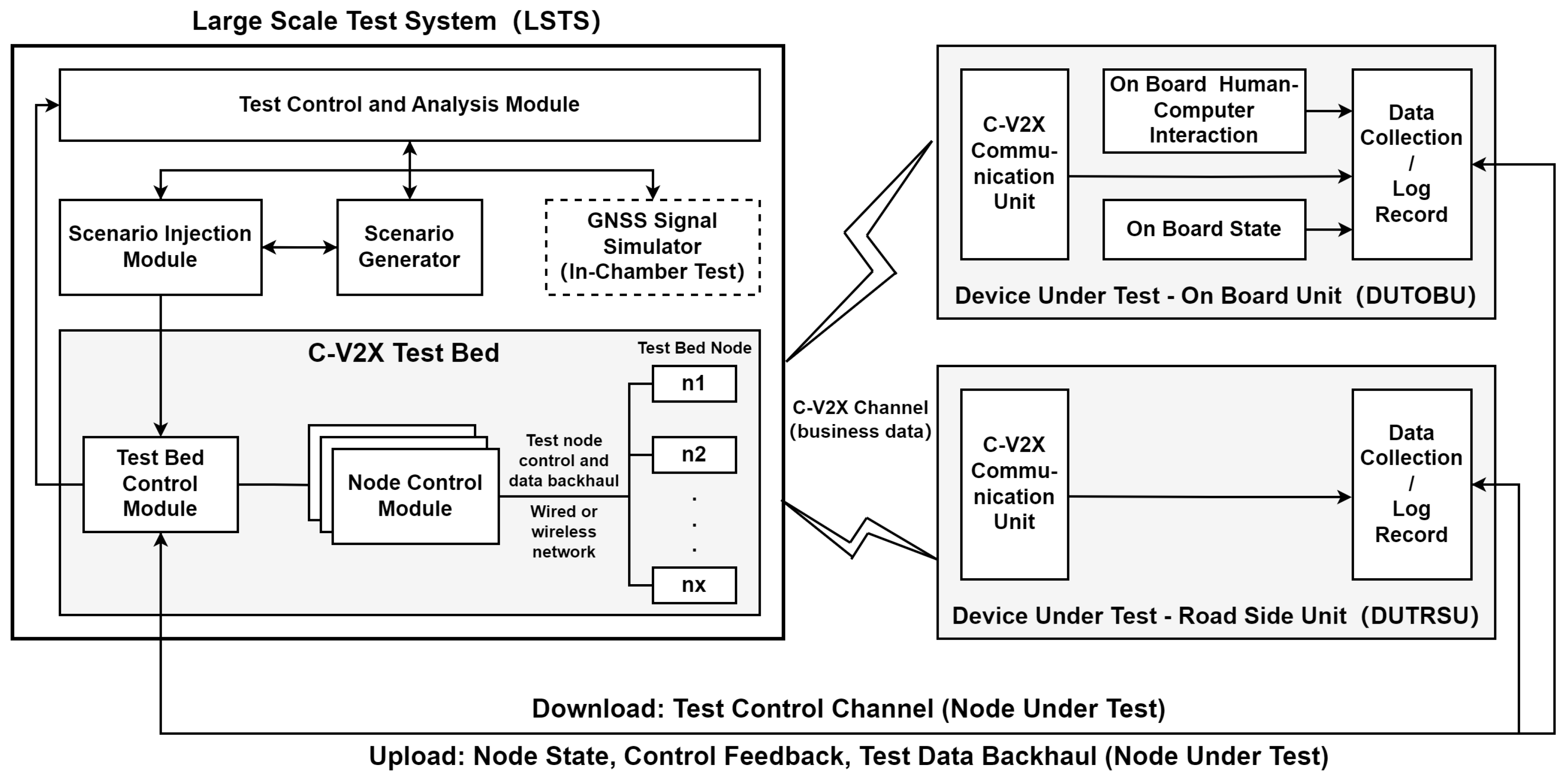
There is no doubt that C-V2X technologies could alleviate communication congestion, which is a severe problem in Dedicated Short-Range Communications (DSRC) [21]. However, OEMs also have some reservations regarding communication performance. Therefore, in 2020, the IMT2020 (5G)-C-V2X group advocated for and organised large-scale tests at the Songhong demonstration area in Shanghai, China. While the test campaign was successful, the offline test data analysis model was controversial. To solve this problem, we developed an automated C-V2X large-scale testing system (LSTS), as shown in Figure 1.
Figure 1.
C-V2X large-scale testing system architecture. System architecture is the fundamental organization of a system, embodied in by components, their relationships to each other and the environment, and the principles guiding its design and evolution [22].
The C-V2X LSTS includes two elements: the testing system (TS) and the Device Under Test (DUT). The validity of the data exchange procedure between the TS and DUT should influence the test experience, e.g., the time required and the accuracy of the results.
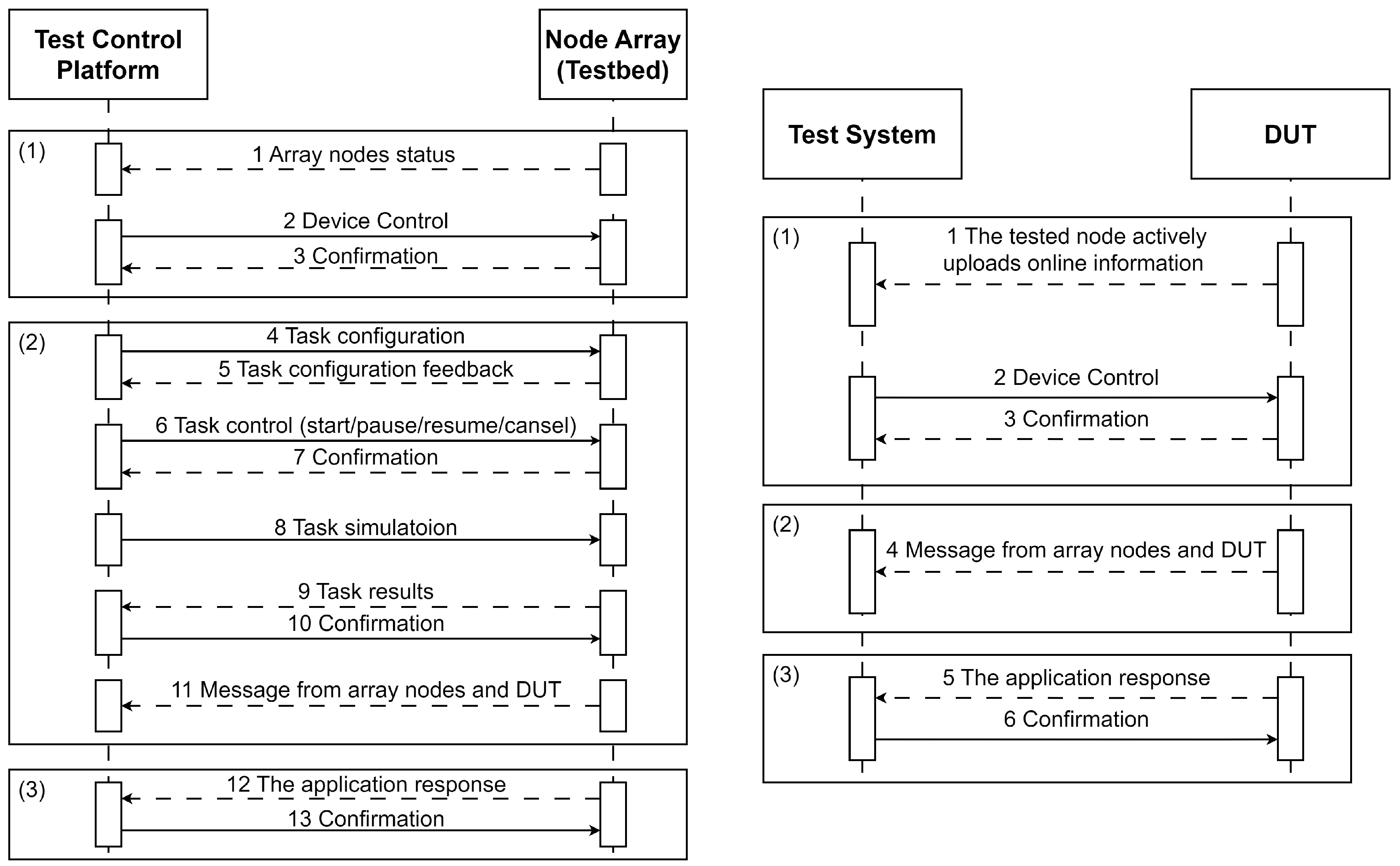
Then, an industry standard [23] published by the Ministry of Industry and Information Technology of the People’s Republic of China, “YD/T 4771-2024 Technical Requirements for C-V2X Large-Scale Testing System and Data Interface”, which defined the corresponding data exchange procedure, was compiled, as shown in Figure 2.

Figure 2.
Data exchange procedure of the C-V2X large-scale testing system.
3.2. Software Functional Analysis
The C-V2X large-scale testing system is primarily designed to investigate communication performance under different regional vehicle density conditions. However, OEMs are concerned about the impact of communication performance on the V2X application response feature. Therefore, the proposed C-V2X LSTS provides communication performance testing and supports scenario-oriented application testing, which are significant challenges in system software design.
As shown in Figure 1, the C-V2X LSTS includes four functional entities: the scenario generator, rgw scenario injection module, the test control and analysis module, and the C-V2X testbed. The first three are run on the test central server, while the last one is deployed on the roadside.
3.2.1. Scenario Generator
The communication environment, constructed with a dense node array, considers communication and environmental factors when designing diverse test cases [4].
Using the DT concept, test scenarios are extracted from on-road traffic data collected by roadside Lidar [20].
Note that this paper focuses on test control software design instead of the test scenario extraction progress. Hence, we assume that a suitable test scenario is selected according to the test task and do not discuss the internal software design of the scenario generator.
3.2.2. Scenario Injection Module
According to the test task command, the scenario injection module recalls scenario information from the scenario generator, establishes a mapping relationship between the scenario vehicles and C-V2X testbed nodes, and injects corresponding information into the C-V2X testbed.
The scenario injection data concern the device control information and vehicle features. Device control information, including the transmit power, frequency, message rate, congestion control scheme, etc., is distributed to nodes when the test is started and stays the same during the test. Vehicle features are converted into Basic Safety Messages (BSMs) that are dynamically and transparently transmitted to the corresponding nodes during the test.
3.2.3. Test Control and Analysis Module
This module is the core of the TS, whose main tasks include test task generation, test execution control, test data analysis, etc.
- Test Task GenerationThe test configuration information from the user will be converted into the test task command to invoke other modules.This conversion is crucial for enhancing user-friendliness, enabling users to overlook the intricacies of the underlying hardware and software.Take a communication scenario, for instance. The test configuration information from the users includes channel-influencing factors, including vehicle density, relative speed, and weather conditions, which will be converted into intricate channel parameters such as Doppler shift, channel fading models, and frequency bands.
- Test Execution ControlTest execution control is the interaction with the scenario injection module, which is the test process triggered by continuous events. Additionally, the TS should provide functions for pausing, terminating, and restarting test tasks to handle potential failures during the tests.
- Test Data AnalysisFor an automatic TS, the real-time test data from the testbed nodes and DUTs are collected and analyzed to monitor the test task’s node status, communication performance, and application scenarios.Based on the test data, the test report is generated according to the requirements of the test.
3.2.4. C-V2X Testbed
The C-V2X testbed consists of a testbed control module, multiple node control modules, and a node array.
The testbed control module distributes the test control information, scenario injection data, and real-time test data backhaul.
3.3. Software Non-Functional Analysis
3.3.1. Node Access and Management
The TS provides the scenario-building function with a controllable number of nodes.
In extreme cases where nodes simultaneously power on and request access, the system must be able to handle the nodes’ access.
In 2018, the Beijing Transportation Committee published road requirements for Beijing’s automatic driving vehicle test roads, which defined four density levels, as shown in Table 2. For instance, when conducting FCW application testing on a road segment that is 150 m long and has two lanes, at least 150 vehicles are recommended to simulate a high-density vehicle environment.
Table 2.
Vehicle density levels.
The node access delay should be manageable, as the typical period for BSM broadcasting is 100 ms [24].
Additionally, since nodes are deployed in outdoor environments, the weather, power supply, and network conditions can affect their connectivity. Therefore, the TS should provide connectivity and availability monitoring for the nodes.
3.3.2. Real-Time Processing of High-Load Concurrent Data
The control of nodes during testing is concurrent, asynchronous, and non-blocking. Given that C-V2X requires the periodic broadcasting of BSM, the network throughput in a C-V2X environment increases exponentially with the number of active nodes. In high-density scenarios, the TS must be able to manage concurrent data under high-load conditions. Therefore, network throughput testing is imperative to ascertain that the system’s throughput remains unsaturated during the concurrent operations of multiple nodes, ultimately preventing performance bottlenecks.
Moreover, V2X applications are inherently time-critical, with rigorous latency requirements in testing, particularly during application testing. Real-time data management is pivotal throughout the execution of each task, entailing meticulous consideration of the accuracy of the data, security, monitoring, and prudent technical selection and system architecture design. Consequently, the TS must guarantee consistent and minimal program response latency across varying load conditions.
3.3.3. Online Graphical User Interface
The V2X industry is a market-oriented application domain. Online GUI exhibits robust interactivity and user-friendliness, which can enhance the efficienct of information transmission, facilitate test monitoring, and support data analysis. GUI is highly beneficial to the development of TS.
It is crucial to note that the GUI’s design must empower users to disregard the operational mechanics of the underlying hardware and software, enabling them to concentrate on configuring scenario parameters pertinent to the test.
This is because the TS’s intended users are administrators and regular users. Administrators represent the testing service providers (equipment or vehicle testing centers), while regular users are the testing acquirers (equipment or vehicle manufacturers). The GUI is the primary object through which users interact with the TS.
3.3.4. Maintenance of the Software
As C-V2X testing and industrialisation advance, the demands regarding TS software escalate.
To adapt to these evolving requirements, the TS design must ensure that resource expansion and function development can be achieved at a low cost and with high efficiency.
Embracing a technology stack with abundant resources and active communities can accelerate the rapid implementation and iteration of new functions and requirements.
Concurrently, adopting an advanced layered and modular design philosophy is paramount, underpinning the system’s adaptability and maintainability.
4. Software Architecture
4.1. Overall Architecture Design
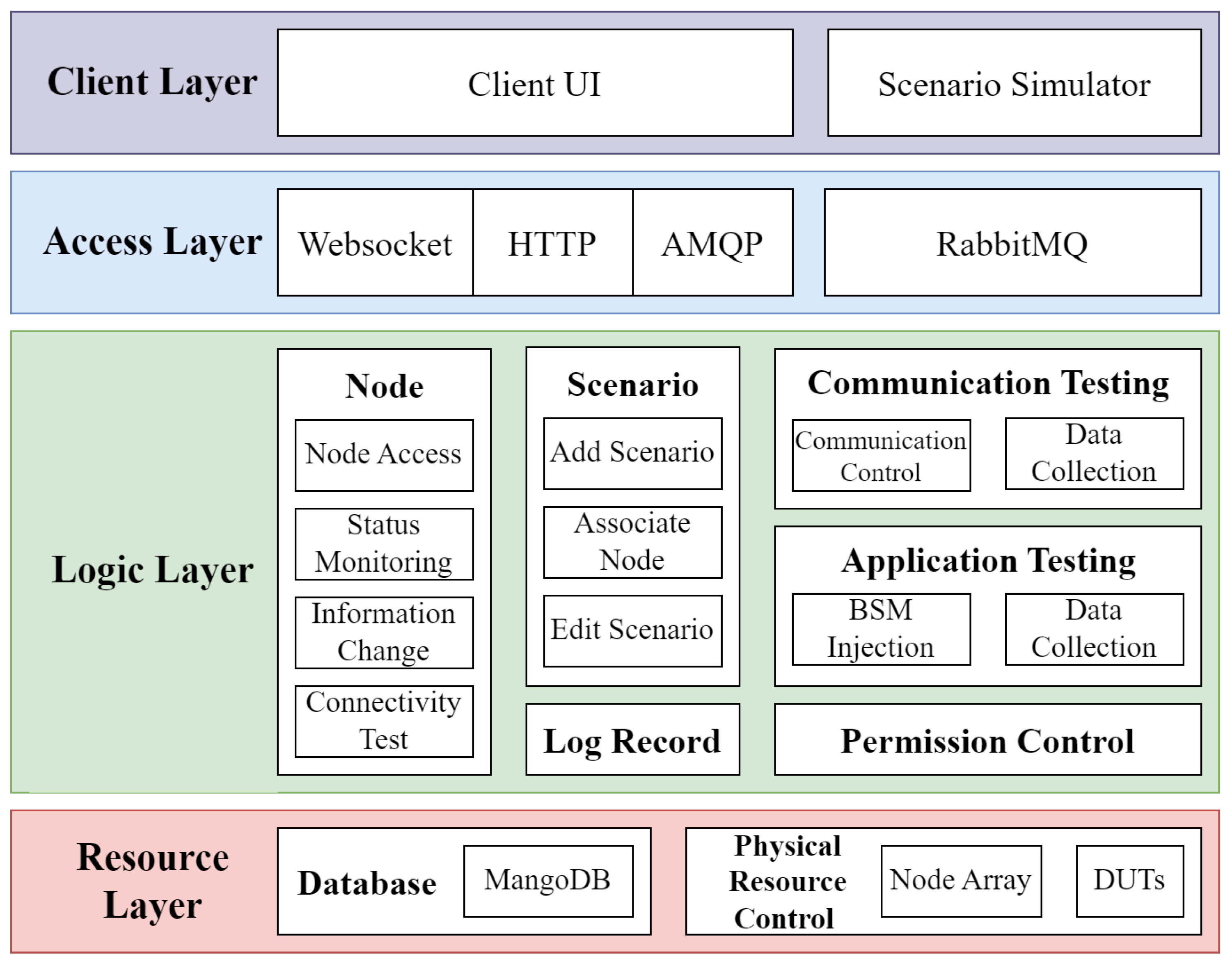
Based on the analysis of system requirements, this paper presents a classic layered software architecture, as shown in Figure 3. In the layered architecture [25], the various levels are isolated and decoupled, making the software easy to test and maintain, with better scalability and reusability.
Figure 3.
Software architecture of the C-V2X large-scale testing system. The software architecture is the organizational structure of a software system, which defines the relationships and interactions between its various components, as well as the overall design scheme [22].
The overall architecture is divided into four layers: the user layer, the access layer, the logic layer, and the software and hardware resource layer. The access layer is mainly used for data interaction between the modules of the user layer and the logic layer. The other layers are detailed below.
- User LayerThis layer has two parts: the client GUI and the scenario simulator. Every user operation is passed to the logic layer to process, and then the client GUI is updated to display related data. The scenario simulator primarily injects scenario data.
- Logic LayerThis layer is the core of the entire system, receiving operations from the user layer on the database or the physical resources while receiving and processing events from the physical resources. It is mainly responsible for scenario and node management, communication testing, application testing, and other services, and conducts data management and hardware operations based on business logic.
- Resource LayerThis layer has physical resources in addition to the database used in classical information systems. The database contains user information, scenario information, node information, test execution information, and test result data. The physical resources mainly refer to the testbed nodes and the DUTs.
4.2. Core Functional Module Design
The C-V2X TS has four functional modules. This section will expand on the functional implementation of these core modules.
4.2.1. Scenario Management Module
The primary functions of the scenario management module include adding new scenarios, associating nodes, and modifying scenarios. Here, the scenario refers to a physical testing site in the actual world.
Nodes are crucial components when constructing the test scenarios. When a node accesses the TS, the user must associate it with the scenario. The association data include the scene to which it belongs and its coordinates.
4.2.2. Node Management Module
The TS must maintain and manage the nodes, including node access, status monitoring, information changes, and connectivity testing.
- Node AccessNode access is the most complex and crucial function of this module. The initial access process is illustrated in Figure 4. It is important to note that the node information stored in the database determines whether a node is accessing the area for the first time.
 Figure 4. Node first access process.Upon powering on, a node will initiate an application that is customized to the OBU manufacturer to connect to the logical controller and upload its MAC address. After the logic controller obtains the node access request and queries it through the database, it will notify the user of the presence of a new online node in the GUI and request the user’s configuration and the authorization data for the node. Subsequently, the controller generates a unique identifier for the node based on its MAC address, notifies the node of its successful access, stores the node information in the database, and updates its access status on the GUI.Nodes without configuration will be automatically shut down after a certain period to free up logical controller resources. Configured nodes will become available resources, entering the node resource pool and being uniformly managed by the logical controller.
 - Status MonitoringThis function includes the ability to view the working status and statistics of the nodes. A node status can be idle, busy, faulty, or disabled. A node fault is critical and needs to be checked by management personnel in a timely manner. Statistical information includes historical working status, network traffic, package quantity, and other data.
- Information ChangeThis function can change and control two aspects of the information. The first is the configuration information, such as the bound physical scenario, node coordinates, and node name. The second is the node status, which turns the node on and off according to the requirements.
- Connectivity TestingThis function confirms the connectivity between the node devices and eliminates hardware faults. The platform supports the development of C-V2X interoperability testing between nodes. If the nodes fail the testing process, their status information becomes faulty.
4.2.3. Communication Testing Module
This module includes communication control and data collection.
- Communication ControlThe accessed nodes serve as the communication resources the system allocates to construct the scenarios.For the communication testing, the environment is constructed based on the device control data, which should be distributed to each node once the task begins.
- Data CollectionThis function collects all C-V2X data from actual testing for a communication performance analysis. Some of the more critical data include the source address, destination address, C-V2X data type, associated task ID, and original C-V2X data.
4.2.4. Application Testing Module
The application testing and communication testing processes are similar; the difference is that the application scenario injection is more complex and runs through the execution of the task. This section only describes the scenario injection process of the application testing module.
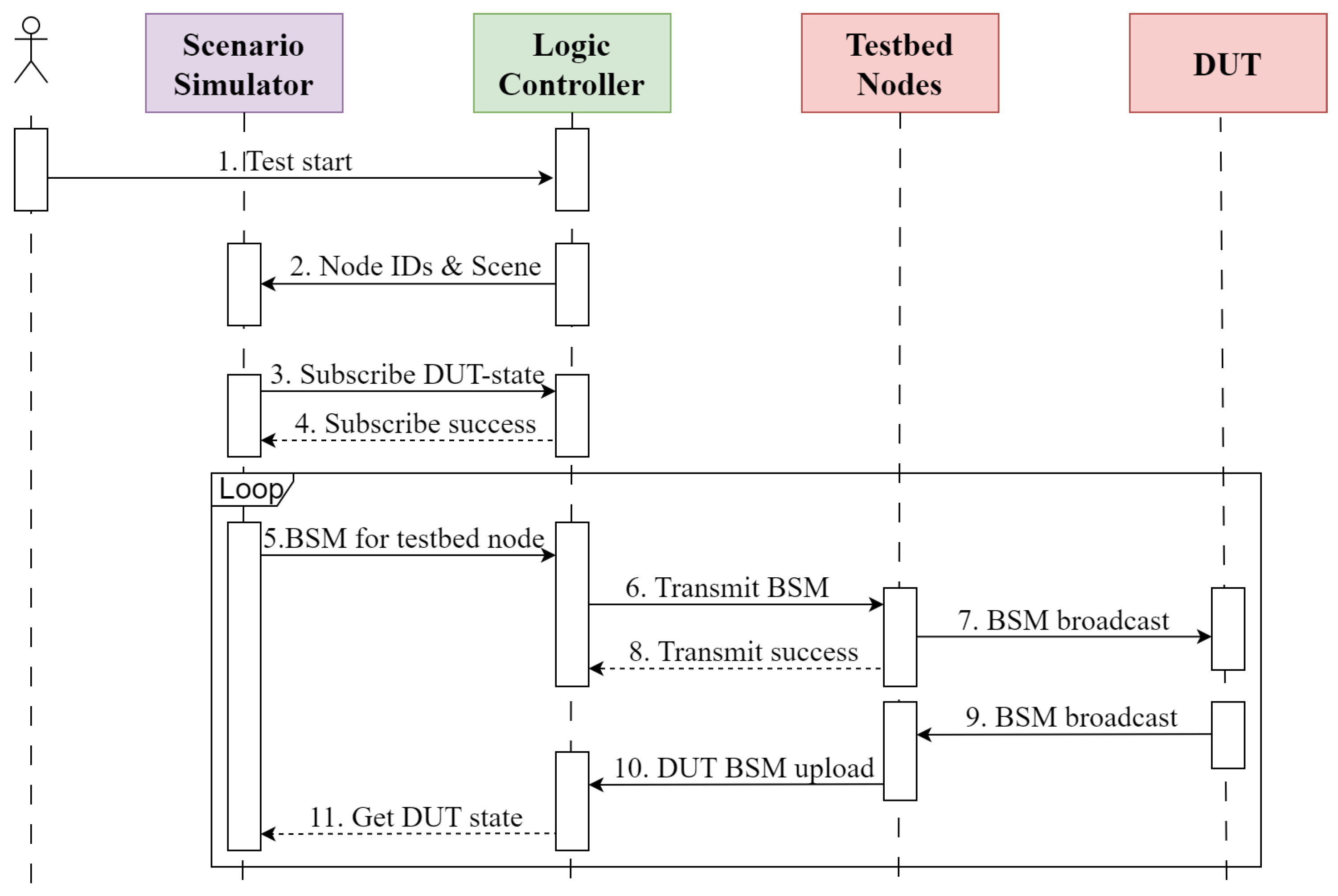
Figure 5 depicts the application’s scenario injection process, which most C-V2X security applications are capable of. The application injection process commences after the device control is completed and the DUT is in place. When the position of the DUT is synchronized with that in the simulator, the vehicle movement scenario simulation is initiated. The BSM content of the testbed nodes is controlled, and the status of the DUT is monitored.
Figure 5.
C-V2X application scenario injection process.
The functions of the involved modules are described below.
- Scenario SimulatorThe simulator models actual physical scenarios and defines vehicle movement models and safety application scenarios to simulate the C-V2X movement scenarios (e.g., FCW).During testing, the simulator specifies the BSM content broadcast by the testbed nodes through the logical controller to inject the application scenarios. Additionally, the simulator subscribes to the status information of the DUT, enabling users to monitor the execution status of the application testing and perform corrections, pauses, or other operations.
- Logical ControllerThis provides the scenario simulator with interfaces for task information acquisition, DUT status subscription, and BSM injection. It collects data from these three interfaces and prepares to analyze the test data.
- Testbed NodesThese nodes broadcast the BSM information injected by the scenario simulator and collect the BSMs broadcast by the DUT to allow for the simulator to obtain the DUT’s status information.
- DUTThis represents the RSU or vehicle provided by the vehicle manufacturer, equipped with C-V2X security applications and operated by the testers. In the test environment, after the application under test is activated, DUTs periodically broadcast BSMs and upload their test data through designated application testing interfaces.
5. Implementation and Deployment
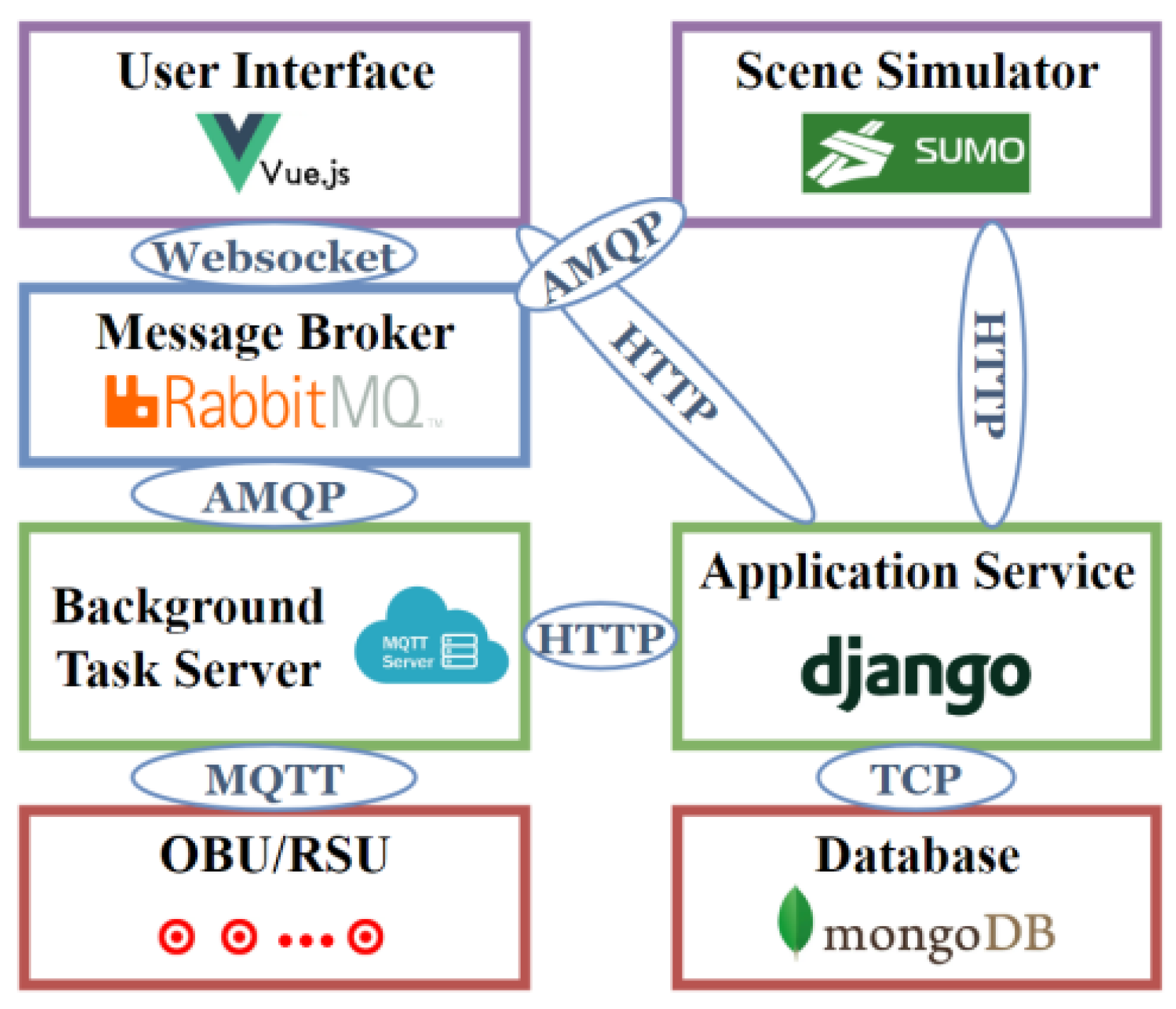
Based on the requirements of the analysis and the introduction of the software architecture, this section provides the related technologies and deployment details. Figure 6 shows the software’s modules and interfaces.
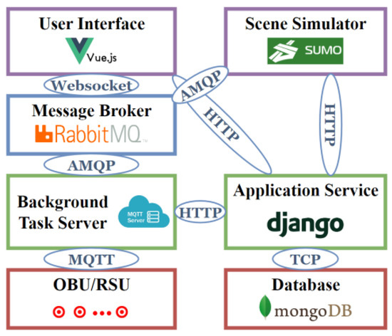
Figure 6.
Software’s modules and interfaces.
5.1. Communication Protocol
The TS must manage many environmental nodes, which requires communication between the nodes and the TS.
The widely adopted Transmission Control Protocol/Internet Protocol (TCP/IP) protocol is suitable for complex network architectures and applications that require high reliability and real-time responsiveness. Consequently, this protocol is not applicable.
As an Internet of Things (IoT) protocol, the Message Queuing Telemetry Transport (MQTT) protocol based on the publish–subscribe mechanism is well-suited for low-bandwidth networks and resource-constrained devices. It supports three Quality of Service (QoS) levels and offers significant advantages, such as flexibility, scalability, and high concurrency. The testing system referenced in the related work [12], and a communication protocol hybrid testbed [26] also utilizes MQTT in its protocol.
It is worth noting that it is necessary to deploy a message broker for MQTT, which decouples the server and client in time and space. Thus, participants only need to focus on the publish–subscribe process to achieve a connection, making the platform’s implementation scheme more flexible.
Based on the analysis above, we adopted the MQTT protocol to ensure the communication and interaction between the nodes and the TS.
5.2. Graphical User Interface
There are two routes for implementing a GUI: application and web development. Application development refers to installing a program on a local computer and utilizing hardware resources to enable the implementation of more sophisticated functionalities. However, this requires higher development costs, has poorer environment compatibility, and leads to a relatively more challenging deployment and maintenance. On the other hand, web development decouples the front end and back end and allows access through a web browser, offering better cross-platform compatibility and user-friendliness. Web development is an excellent choice to achieve GUI.
Abandoning traditional web development methods (HTML, CSS, JavaScript), the MERN stack [27], which consists of four key technologies—MongoDB, Express.JS, React.JS, and Node.JS—has gained more traction as it allows for smooth development and faster deployment. However, due to its short development time, MERN needs to be further developed and the key technologies must be improved. Considering the small size, low complexity, and high flexibility required for its development, the front-end and back-end architecture are also a good choice for web interface development.
Within the domain of front-end development, frameworks like Vue.js, Angular.js, and React.js have garnered substantial acclaim among developers for their ability to streamline the development process. Vue.js, a progressive JavaScript framework for building user interfaces, follows a data-driven and component-based paradigm, providing excellent flexibility and user-friendliness. Notably, Vue.js excels in the realm of lightweight framework development.
Regarding back-end development, popular frameworks such as Django, Flask, and FastAPI come to the forefront. Django, in particular, stands out as one of the most widely embraced and extensively utilized frameworks. Its primary objective is to facilitate the swift and straightforward development of database-driven websites. In comparison, Django is a feature-rich framework that offers an array of built-in functionalities and extensions, making it well-suited to large-scale applications.
Django is famous for its security and scalability, while Vue.js has a low learning curve that attracts the developer community [28]. Skin cancer detection interactive applications [29], the Apache Airavata science gateway middleware project [30], and the public health inspection application [31] have used Django and Vue.js to build their systems.
In conclusion, we selected the Vue.js and Django schemes to implement the GUI.
5.3. Traffic Simulation Software
Traffic simulation software can fulfil the requirements of a scenario simulator for vehicle motion scenario simulations. We selected the current mainstream simulation software, SUMO. The simulation platform [32] of MCity 2.0 was established based on SUMO. Veins [33], and the Internet of Vehicle (IoV) simulation platform combining the existing network simulation software and traffic simulation software also selected SUMO to support its traffic simulations.
Eclipse SUMO [34] is a free and open-source traffic simulation suite. It has been available since 2001 and allows for the modeling of intermodal traffic systems, including road vehicles, public transport, and pedestrians. SUMO includes a wealth of supporting tools that automate core tasks in the creation, execution, and evaluation of traffic simulations, such as network import, route calculations, visualization, and emission calculations. SUMO can be enhanced with custom models and provides various APIs to control the simulation remotely.
5.4. Message Broker
V2X is a typical distributed system with high-speed dynamic topology changes and many participants. The TS must achieve high-concurrency data transmission, affecting its reliability and availability.
Modern messaging systems are built on top of Message-Oriented Middleware (MOM) architectures, leveraging two paradigms, the publish–subscribe mechanism and message queue, to help build scalable and loosely coupled systems [35]. Familiar message brokers include Kafka, ActiveMQ, and RabbitMQ. Among the three, Kafka has the best throughput and high-availability performance, ActiveMQ is more frequently used in enterprises, and RabbitMQ has a good concurrency capability owing to the Erlang development language [35,36,37]. Furthermore, RabbitMQ [38] supports multiple open-source standard protocols.
We selected RabbitMQ as the message broker for high-concurrent information transmission between modules.
5.5. Database
Databases enable the effective organization, storage, and management of data. Compared to relational databases, non-relational databases handle unstructured data, support high concurrency, and accommodate the storage of massive amounts of data [39]. We selected MongoDB to support the database function. MongoDB, a document-oriented Non-relational SQL (NoSQL) database, is an ideal choice for storing object-type data and supports intricate query operations.
5.6. Test Procedure
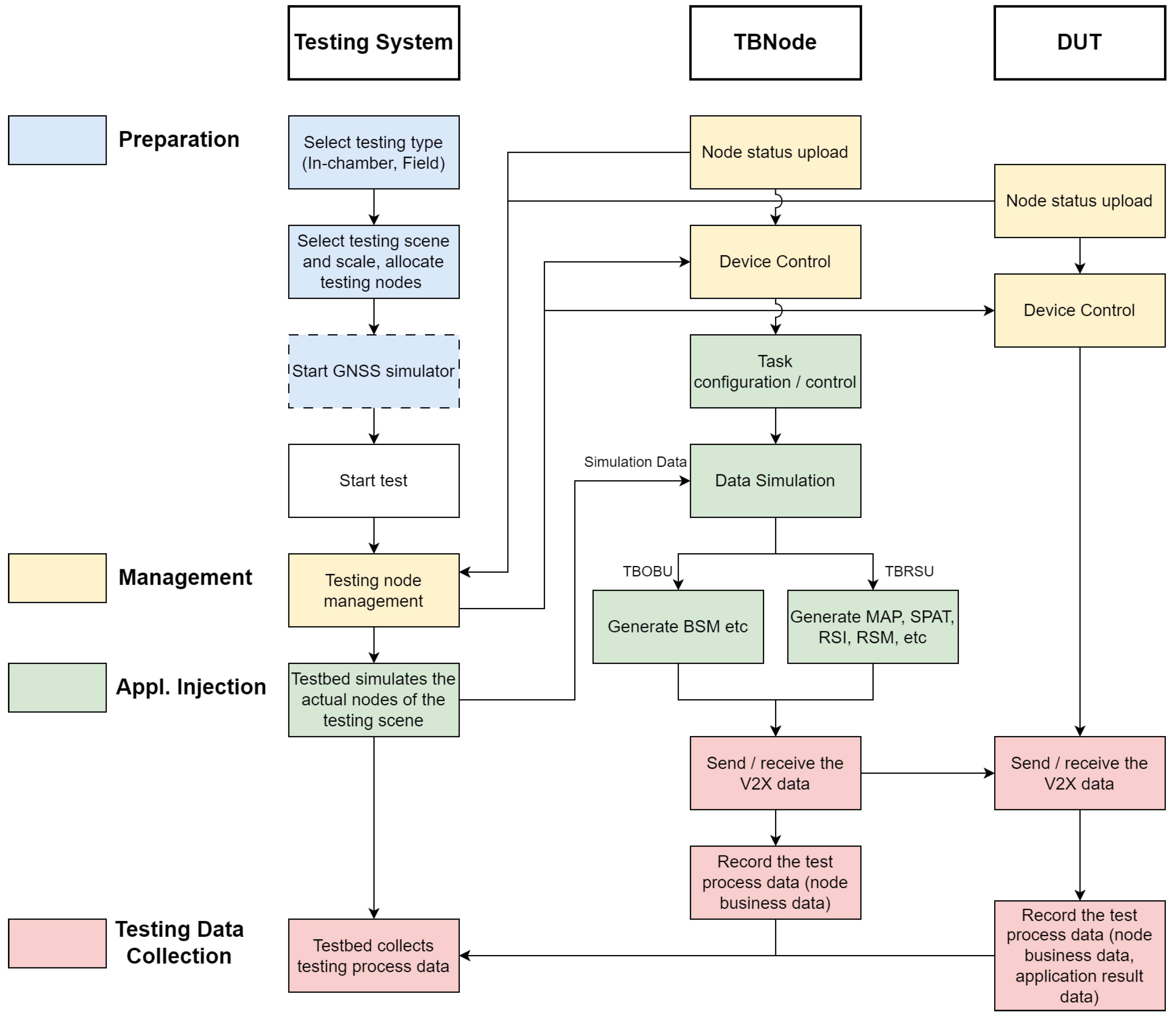
To promote the C-V2X field testing standardization process, we combined many vehicle test originations, Tier 1 companies, and OEMs to discuss the test data interface’s specifications, including the test process, data exchange process, and data interface norm. In March 2021, the standard project was approved by the China Communication Standard Association (CCSA), while a series of tests were conducted to improve the validation of the proposed method. Figure 7 shows the test process of the TS.

Figure 7.
Testing system’s test process.
This test system supports two types of test objects, vehicles and roadside systems, and covers indoor and field testing environments.
By incorporating a GNSS signal simulator, the system can perform testing functions in an indoor environment. Specifically, the simulator provides the necessary satellite positioning signal conditions (including module communication and timing services) for all V2X terminals and transmits satellite navigation data to the DUT.
The following diagram provides a detailed overview of the main processes in the test system. These processes can be divided into four stages: preparation, test management, application scenario injection, and test data collection.
- Preparation StageThis stage mainly involves setting up the test type, scenario, and scale.Firstly, the test type must be specified, i.e., whether indoor or field tests are being conducted. Subsequently, the corresponding test scenario and scale are selected, and testbed nodes are allocated accordingly. The test scenario here refers to the actual physical environment; the allocated nodes are the device nodes connected to that physical environment.The GNSS signal simulator will provide satellite signals for field tests and timing services and simulated positioning functions for indoor tests.
- Test Management StageThis stage focuses on node management, task configuration, and task management.Once the test is officially initiated, the testbed will receive real-time status data from testbed nodes (including TBOBU and TBRSU) and the DUT to manage these nodes.Management includes device control (such as device on/off, start/stop of data reporting, congestion control activation/deactivation, device restart, and command execution), task configuration (such as setting test task types, configuring data content), and task management (including task start, pause, resume, and end).Notably, task configuration and task management functions are only practical for testbed nodes.
- Application Scenario Injection StageThe testbed generates and transparently transmits realistic scenario data simulated by the node array.This stage involves communication scenarios and application scenarios. Data injection for static communication scenarios originates from task configuration information, specifically including parameters such as node message transmission power and broadcast message frequency. Data injection for application scenarios is dynamically generated by the testbed and transparently transmitted to the testbed nodes in real-time.After receiving the scenario messages simulated by the test system, the testbed nodes will send out V2X-simulated data, completing the entire scenario injection process.
- Test Data Collection StageTest data are continuously collected during the test run for subsequent analysis and evaluation.During the test, the testbed nodes send out V2X-simulated data and transmit their business data back to the C-V2X testbed.Simultaneously, the DUT will send its data and receive V2X-simulated data to trigger corresponding scenarios. Subsequently, the DUT will transmit its business data and application result data back to the C-V2X testbed.
The test system can efficiently and accurately complete various testing tasks through these four closely interconnected stages.
6. System Performance and Test Case Analysis
This section will describe the test environment and test conditions of the implemented C-V2X scale-up test platform, demonstrate the test system’s large-scale load performance, explore the impact of the communication environment on its application, and validate the platform’s usability through the application of FCW safety warnings.
6.1. Testing System Performance for Large-Scale Loads
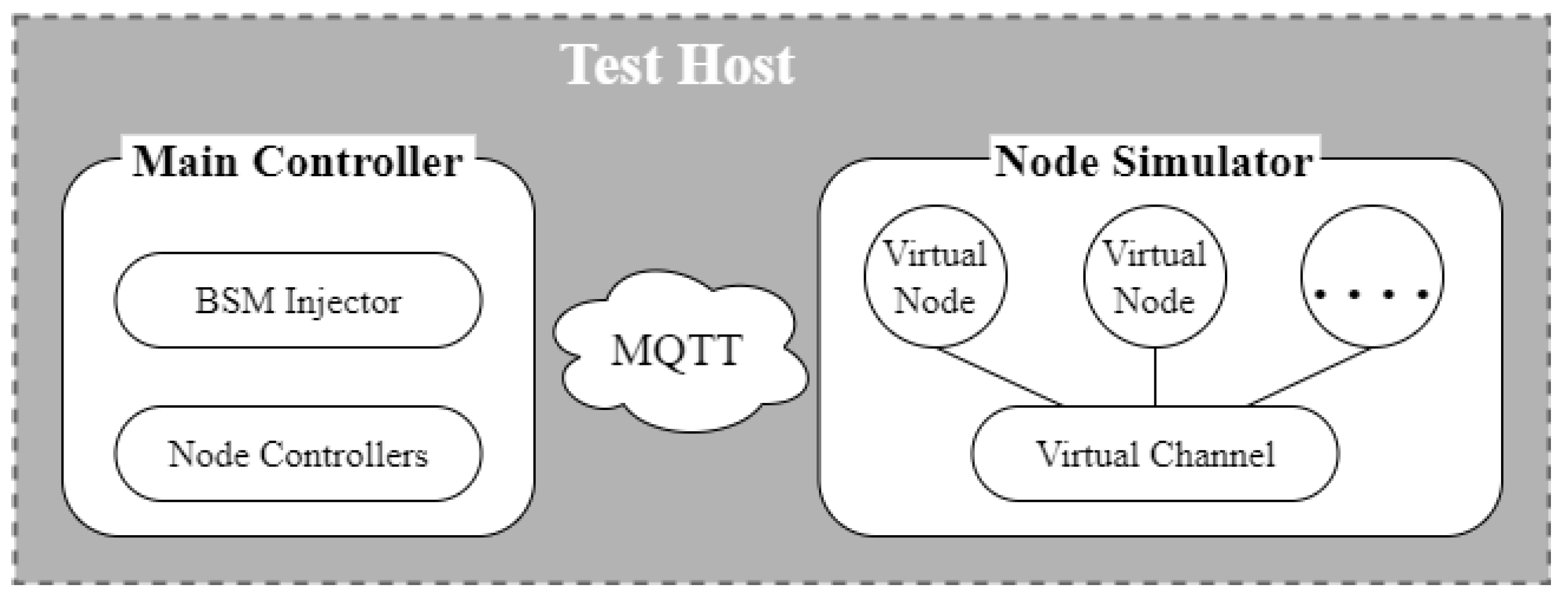
Large-scale arrays of nodes are at the heart of the test system, but they pose a challenge to the system performance. This subsection verifies the large-scale load performance of the software architecture. The test focuses on evaluating the performance of the master controller under high- and regular load conditions.
Since hardware nodes are costly, developing virtual nodes with node interfaces and logic is necessary as an alternative. As shown in Figure 8, we set up a test environment, deploying the master controller and node simulators on a single test host. The load on the master controller was divided into two scenarios: the number of nodes accessed and the tasks executed by the nodes. The node simulators can simulate a specified number of nodes based on configurations and create virtually ideal communication channels within the environment.
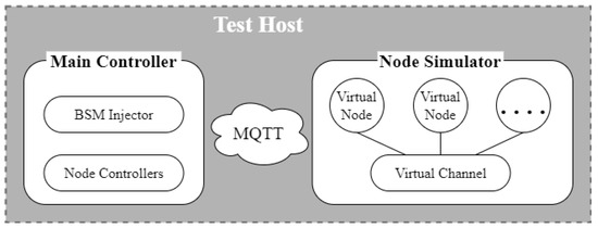
Figure 8.
Schematic diagram of the load test environment.
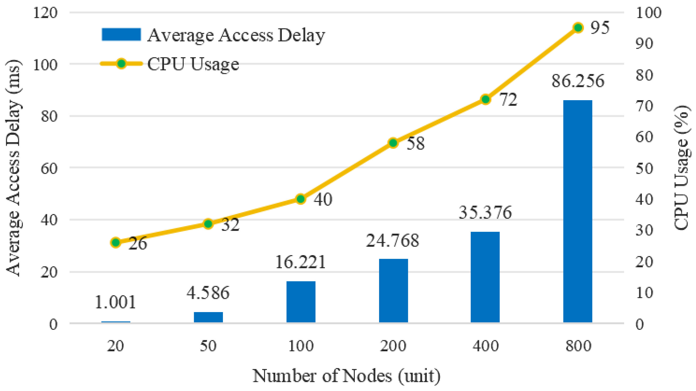
6.1.1. High-Load Performance Test
A high-load performance test aims to determine the maximum number of accessible nodes for the test host and the average node access delay at different scales.
Here are the relevant parameter settings for the high-load performance testing:
- Basic configuration of test controller: Intel(R)i5-10400 6core 16 G RAM (Intel, Santa Clara, CA, USA);
- Number of under-test nodes: 20, 50, 100, 200, 400, 800;
- Heartbeat interval: 5 s;
- BSM: 10 Hz.
The test results are shown in Figure 9. When the number of nodes is 200, the average node access delay is approximately 25 ms, less than the BSM propagation interval of 100 ms. When the CPU utilization rate reaches 95%, and the number of nodes is 800, the average node access delay is approximately 87 ms, which still meets the requirements.
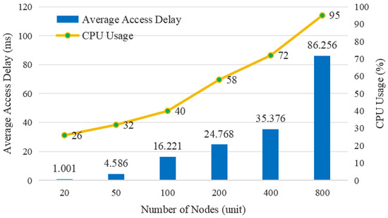
Figure 9.
High-load performance test results.
Therefore, the proposed testing system can meet the requirements of C-V2X field testing and has sufficient redundancy to support the practical use of subsequent testing platforms.
6.1.2. Regular Load Performance Test
The purpose of the regular load performance test is to obtain the network throughput faced by the master and the average BSM pass-through interface latency under load, which is closely related to the effectiveness of the test system solution.
Here are the relevant parameter settings for the regular load performance test:
- Testing hardware environment: MacBook Air (M1) 8 G RAM (Apple, Cupertino, CA, USA);
- Number of nodes accessed: 10, 20, 30, 40, 50;
- BSM frequency: 10 Hz, 20 Hz, 30 Hz.
Table 3 shows the results of the regular load performance test of the master controller. When deploying a scenario with 50 nodes broadcasting Basic Safety Messages (BSMs) at a frequency of 30Hz, it can simulate 150 vehicles, effectively mimicking extreme congestion in a real-world physical scenario. As indicated in the table, when the number of nodes is 50, the master controller experiences a peak data throughput of 127 Mbps. However, it still provides an average response delay of 0.58 ms for BSM transparent transmission. Across all testing conditions, the response delay fluctuates between 0.38 ms and 0.6 ms, remaining unaffected by the task load on the master controller.
Table 3.
Regular load performance test results.
6.2. FCW Test Case
6.2.1. Field Testing Environment
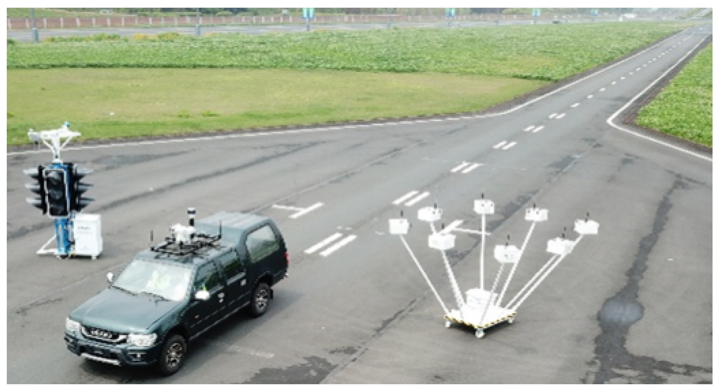
The TS is deployed in the experimental field of Chongqing Motor Vehicle Mandatory Test Center. The testing center has an internal enclosed road, as shown in Figure 10. It provides C-V2X DUTs from two Tier 1 suppliers, all installed on the vehicles under test.

Figure 10.
Field Testing environment and equipment.
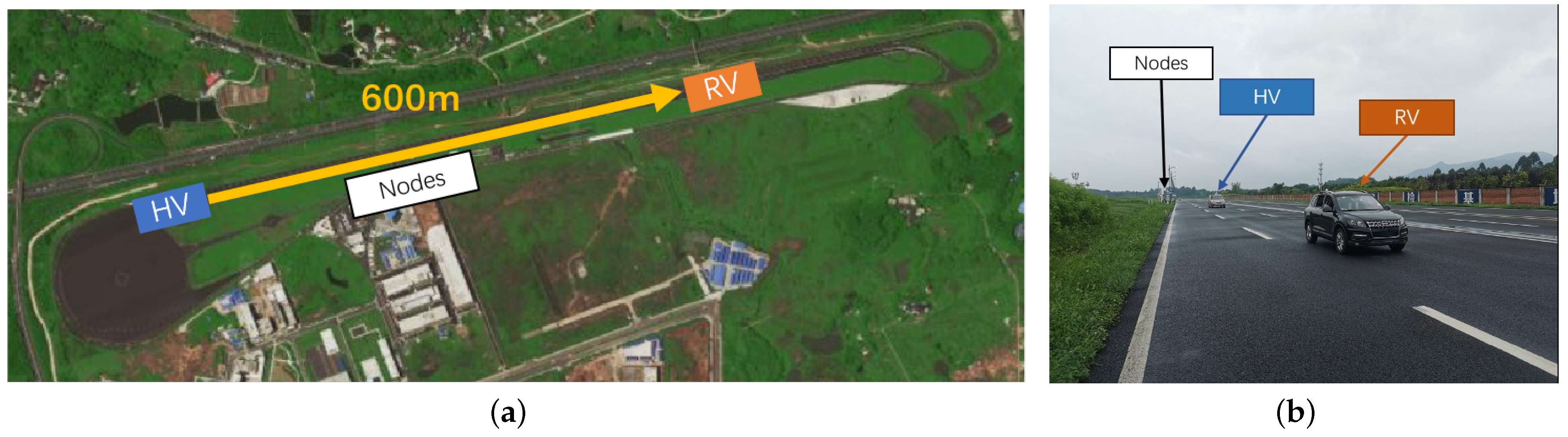
Figure 11 depicts the deployment of the test scenario, where a 600 m long straight road is selected for this test, with the RV and the HV positioned 600 m apart from each other. Two node arrays, which could simulate 200 vehicle nodes, are placed 50 m apart.
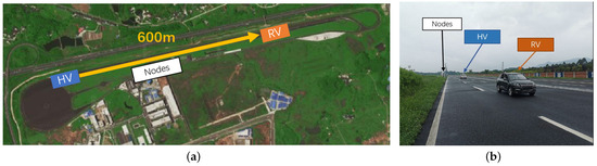
Figure 11.
Test scenario deployment diagram:(a) straight road; (b) FCW testing scene.
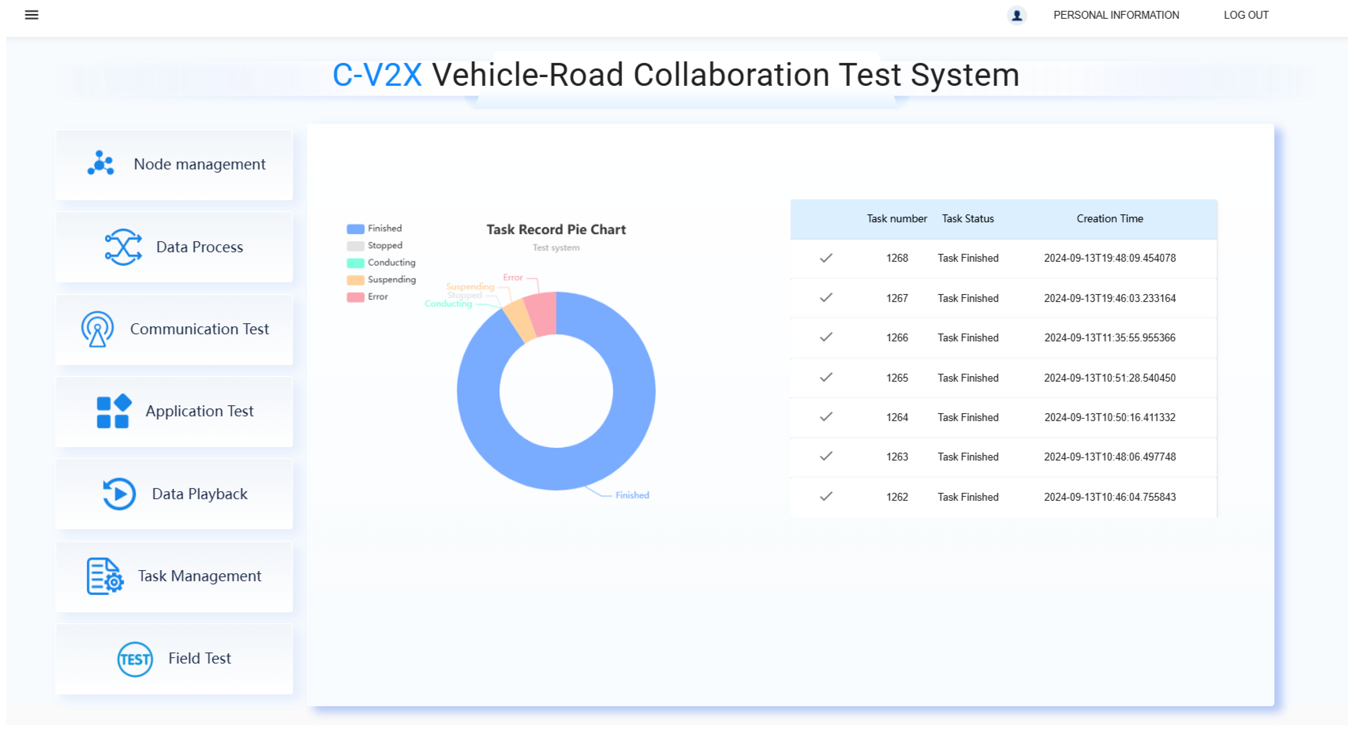
Once the hardware equipment is deployed, automated C-V2X testing, including test configuration, monitoring, and test results, can be achieved through an online GUI according to the system’s user instructions. Figure 12 displays the administrator login interface of the GUI. Administrator users can view all task executions and completions and access all task reports.
Figure 12.
The administrator login interface of the GUI.
6.2.2. Testing Procedure and Results’ Analysis
Based on the research report DOT HS 811 501 by the National Highway Traffic Safety Administration (NHTSA) [40], we designed an FCW test scheme and conducted case tests.
Next, we will introduce the FCW test requirements, test procedures, and test results’ analysis.
- •
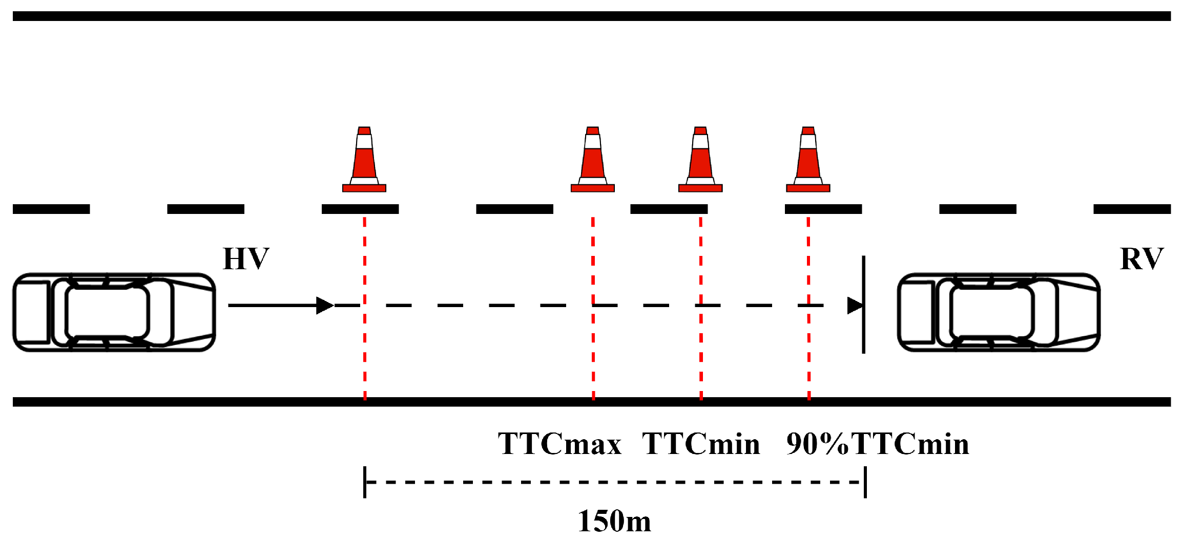
- Test RequirementsThe test requires that the DUTs have a communication range greater than 300 m, a data update frequency (i.e., transmission frequency) of less than or equal to 10 Hz, a system latency of less than or equal to 100 ms, and a positioning error of less than or equal to 1.5 m.The test expects the HV to issue a forward collision warning between the distance points marked in Figure 13, which are (≈55.56 m) and (≈29.17 m). Here, is 4 s, and is 2.1 s, as defined in DOT HS 811 501. TTC refers to Time To Collision.
 Figure 13. FCW testing procedure.
 - •
- Test ProceduresThe FCW test procedure is as follows:
- –
- The HV is parked at the center of the lane, 600 m from the RV. Its longitudinal direction is parallel to the road edge, facing in the same direction as the RV.
- –
- The HV accelerates straight ahead until it reaches a constant speed of 50 km/h before reaching a distance of 150 m from the RV.
- –
- Test recording begins when the HV is 150 m away from the RV.
- –
- The test ends when one of the following conditions occurs: a. The FCW alarm is triggered by the HV between the distance points of (≈55.56 m) and (≈29.17 m); b. the HV fails to trigger the FCW alarm before reaching the distance point of ; c. the HV triggers the FCW alarm before reaching the distance point of ; d. a false alarm is triggered.
- –
- After the test, the HV should turn (recommended) or brake to avoid colliding with the RV.
- –
- The real-time speeds, travel trajectories of both the HV and RV, the FCW application warning time, and the FCW application warning distance are recorded.
- •
- Test Result AnalysisThe application response feature is shown in Figure 14, while the communication performance is shown in Figure 15. The test was repeated ten times under each working condition.
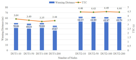 Figure 14. Application response performance.
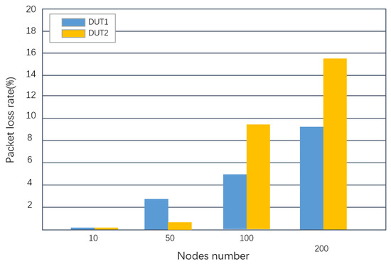 Figure 15. Packet loss rate.As shown in Figure 14, the FCW TTC value declines slightly with the increase in node density. Moreover, there were differences in response time TTC between products from different Tier 1 vendors. One possible reason for this is the difference between the application response algorithms. Nevertheless, the overall, TTC performance was relatively stable.As shown in Figure 15, the packet loss rate rises with the increase in node density. 3GPP has specified quantitative performance requirements for advanced V2X applications in TS 22.186; the reliability range for these applications is 90% to 99.999% [41]. This implies that, for V2X applications, the maximum packet loss rate should not exceed 10%, as a higher rate would indicate a severely degraded communication environment.Comparing Figure 14 and Figure 15, we can conclude that communication performance has a limited impact on response time TTC. Even when the packet loss rate reaches 15.6%, FCW response time TTC is also higher than the value, which is 2.1 s. The above test results prove the effectiveness of C-V2X technologies from another perspective.
7. Discussion
7.1. System Effectiveness Comparison and Analysis
In the previous section, the system’s scalability and functionality were validated, yet the effectiveness of the simulated scenarios within the TS remains open to question. For application scenarios, the participation of key vehicles (HV, RV) is authentic and valid. However, for communication scenarios, the performance evaluation of the TS necessitates further verification.
In our previous work [4], we conducted a comparison between the communication performance evaluation of the TS and that of the NS-3 simulation. In highway scenarios, the difference in Packet Delivery Delay (PDD) between the two was approximately 2.02%, while the difference in Packet Delivery Ratio (PDR) was about 0.19%. For urban road scenarios, the discrepancy in PDD was roughly 3.72%, and the discrepancy in PDR was approximately 1.89%.
The large-scale LTE-V2X test platform [18], with 198 OBUs deployed, was also cross-validated for the intersection scenario. They found that the difference in Packet Error Rate (PER) was approximately 3%, and the difference in average communication delay was about 7.4%. Additionally, the trends for evaluation parameters (Inter-Transmission Time (ITT), Channel Busy Ratio (CBR), and PER) remained consistent.
It can be observed that this large-scale field testing scheme is practical, yet the analytical parameters of the TS we proposed need to be revised.
7.2. System Continuous Development
Scenarios are at the core of our proposed TS, and 3GPP has stipulated numerous V2X application instances. New scenarios need to be developed, debugged, and improved to promote the TS before it can be applied.
Scenario generators, standardized data exchange interfaces, and full-process automated monitoring greatly assist in this process.
When a new application requirement arises, the first step is to use the scenario generator to extract the corresponding application scenario. Subsequently, an application testing plan is designed, and the application development is completed through indoor and field testing.
In this process, standardized interfaces enable functional testing by simply adding interactive interfaces to the DUT. For the specific contents of the standardized interface, please refer to the industry standard [23].
If testing issues arise, TS developers can review the problem tasks and resolve the issues based on the test data recorded in the database.
8. Conclusions
In the realm of ICV, its profound integration across industries stands out as a notable characteristic, and it also presages the development of general testing and assessment systems as an inevitable trend. Currently, most test schemes are centered on application testing, ignoring the comprehensive integration requirements of various test types, such as communication, interoperability, consistency, and network security. Notably, OEMs have paid keen attention to how the communication environment impacts the response characteristics of applications.
Given our previous work constructing a large-scale C-V2X testing system for communication testing, we recognize that integrating communication testing with application testing poses significant challenges to system software development. Consequently, we propose a layered software architecture for a highly automated, large-scale C-V2X testing system tailored to combined scenarios.
At the core of this architecture lies the scenario encapsulation technology, which enables communication testing and application validation under many scenarios through the deployment of a flexibly adjustable node array. Furthermore, during the architectural design process, we thoroughly considered the system’s non-functional requirements, encompassing real-time system status monitoring, high-concurrency data-processing capabilities, real-time data management, and a user-friendly online visualization interface.
The experimental results demonstrate that the proposed layered architecture, along with the communication protocol and technology stack that were used, fulfills the requirements for the TS in terms of validity, scalability, and stability.
For future work, we will continuously optimize the TS and further explore digital twin TS grounded in the integrated vehicle–road–Cloud framework. By leveraging efficient information interaction and coordination mechanisms among vehicles, road infrastructure, and cloud servers, we will construct digital test scenarios and investigate V2X test strategies in which the testing and actual operation reinforce each other, thereby enhancing test coverage and efficiency.
Author Contributions
Conceptualization, Q.H., L.Z., L.Y. and F.X.; methodology, L.Z., M.Z. and F.X.; software, M.Z., M.T. and F.X.; validation, L.Z., Q.H. and L.Y.; formal analysis, L.Z., M.Z., M.T. and F.X.; investigation, L.Z., M.Z., M.T. and F.X.; resources, L.Z., Q.H. and L.Y.; data curation, L.Z. and F.X.; writing—original draft preparation, Q.H. and M.Z.; writing—review and editing, Q.H., M.Z., L.Z., L.Y., M.T. and F.X.; visualization, M.Z. and M.T.; supervision, L.Z. and Q.H.; project administration, L.Z.; funding acquisition, L.Z., Q.H. and L.Y. All authors have read and agreed to the published version of the manuscript.
Funding
This research was funded by the Chongqing Technology Innovation and Application Development Special Project (Grant No. CSTB2022TIAD-STX0001 and Grant No. cstc2021jscx-gksbX0057) from the Chongqing Science and Technology Bureau.
Institutional Review Board Statement
Not applicable.
Informed Consent Statement
Not applicable.
Data Availability Statement
The data presented in this study are available on request from the corresponding author. The data are not publicly available due to privacy.
Conflicts of Interest
The authors declare no conflicts of interest.
References
- Wang, J.; Shao, Y.; Ge, Y.; Yu, R. A Survey of Vehicle to Everything (V2X) Testing. Sensors 2019, 19, 334. [Google Scholar] [CrossRef] [PubMed]
- MCity. Available online: https://mcity.umich.edu/ (accessed on 7 May 2024).
- Astazero. Available online: https://www.astazero.com/ (accessed on 11 May 2024).
- Han, Q.; Yuan, X.; Zeng, L.; Zu, H.; Ye, L.; Lin, L. Scenario Oriented V2V Field Test Scheme with Dense Node Array. In Proceedings of the 2020 IEEE 23rd International Conference on Intelligent Transportation Systems (ITSC), Rhodes, Greece, 20–23 September 2020; pp. 1–6. [Google Scholar]
- Gani, S.M.O.; Fallah, Y.P.; Krishnan, H. Robust and Scalable V2V Safety Communication Based on the SAE J2945/1 Standard. IEEE Trans. Intell. Transp. Syst. 2022, 23, 861–872. [Google Scholar] [CrossRef]
- Facchina, C.; Jaekel, A. Speed Based Distributed Congestion Control Scheme for Vehicular Networks. In Proceedings of the 2020 IEEE Symposium on Computers and Communications (ISCC), Rennes, France, 7–10 July 2020; pp. 1–4. [Google Scholar]
- Lindstedt, R.; Kasparick, M.; Pilz, J.; Jaeckel, S. An Open Software-Defined-Radio Platform for LTE-V2X And Beyond. In Proceedings of the 2020 IEEE 92nd Vehicular Technology Conference (VTC2020-Fall), Victoria, BC, Canada, 18 November–16 December 2020; pp. 1–5. [Google Scholar]
- Li, L.; Wu, X.; Jiang, G.; Feng, J.; Zhang, X. A Virtual Driving Testing Method for C-V2X Performance Evaluation. In Proceedings of the 2021 IEEE International Workshop on Electromagnetics: Applications and Student Innovation Competition (iWEM), Guangzhou, China, 28–30 November 2021; Volume 1, pp. 1–3. [Google Scholar]
- Makinaci, K.M.; Acarman, T.; Yaman, C. Resource Selection for C-V2X and Simulation Study for Performance Evaluation. In Proceedings of the 2021 IEEE 93rd Vehicular Technology Conference (VTC2021-Spring), Helsinki, Finland, 25–28 April 2021; pp. 1–6. [Google Scholar]
- Malinverno, M.; Raviglione, F.; Casetti, C.; Chiasserini, C.F.; Mangues-Bafalluy, J.; Requena-Esteso, M. A Multi-stack Simulation Framework for Vehicular Applications Testing. In Proceedings of the 10th ACM Symposium on Design and Analysis of Intelligent Vehicular Networks and Applications, New York, NY, USA, 16–20 November 2020; pp. 17–24. [Google Scholar]
- Farag, M.M.G.; Rakha, H.A.; Mazied, E.A.; Rao, J. INTEGRATION Large-Scale Modeling Framework of Direct Cellular Vehicle-to-All (C-V2X) Applications. Sensors 2021, 21, 2127. [Google Scholar] [CrossRef]
- Marchetta, A.; Coppola, A.; Cinque, M.; Fiorentino, M.; Bifulco, G.N. An Eclipse MOSAIC-Based Hardware-in-Loop V2X Co-Simulation Framework for CCAM Services. In Proceedings of the 2023 IEEE 26th International Conference on Intelligent Transportation Systems (ITSC), Bilbao, Spain, 24–28 September 2023; pp. 5357–5362. [Google Scholar]
- Schiel, B.; Swindler, S.; Farmer, A.; Sharp, D.; Murali, A.H.; Corry, B.; Lundrigan, P. A Multi-layered Framework for Informing V2I Deployment Decisions Using Commercial Hardware-in-the-Loop Testing of RSUs. In Proceedings of the 2024 IEEE Vehicular Networking Conference (VNC), Kobe, Japan, 29–31 May 2024; pp. 313–320. [Google Scholar]
- Peters, S.; Sivrikaya, F.; Dang, X.T. SEP4CAM—A Simulative / Emulative Platform for C-V2X Application Development in Cross-Border and Cross-Domain Environments. In Proceedings of the 2021 IEEE/ACM 25th International Symposium on Distributed Simulation and Real Time Applications (DS-RT), Valencia, Spain, 27–29 September 2021; pp. 1–4. [Google Scholar]
- Chen, D.; Yan, Y.; Ye, L.; Hu, H.; Lei, J.; Zeng, L. On-road Features Based In-chamber C-V2X Application Test Scheme Design. In Proceedings of the 2022 IEEE Smartworld, Ubiquitous Intelligence & Computing, Scalable Computing & Communications, Digital Twin, Privacy Computing, Metaverse, Autonomous & Trusted Vehicles (SmartWorld/UIC/ScalCom/DigitalTwin/PriComp/Meta), Haikou, China, 15–18 December 2022; pp. 2191–2197. [Google Scholar]
- Marquez-Barja, J.; Lannoo, B.; Naudts, D.; Braem, B.; Maglogiannis, V.; Donato, C.; Mercelis, S.; Berkvens, R.; Hellinckx, P.; Weyn, M.; et al. Smart Highway: ITS-G5 and C-V2X based testbed for vehicular communications in real environments enhanced by edge/cloud technologies. In Proceedings of the European Conference on Networks and Communications (EuCNC), Valencia, Spain, 18–21 June 2019. [Google Scholar]
- Charpentier, V.; Slamnik-Krijestorac, N.; Marquez-Barja, J. Latency-aware C-ITS application for improving the road safety with CAM messages on the Smart Highway testbed. In Proceedings of the IEEE INFOCOM 2022—IEEE Conference on Computer Communications Workshops (INFOCOM WKSHPS), New York, NY, USA, 2–5 May 2022; pp. 1–6. [Google Scholar]
- Wang, J.; Ying, T.; Zhu, K.; Zhang, L.; Zhang, F.; Wang, Y. Large scale LTE-V2X Test Attempt via Real Deployment. In Proceedings of the 2022 IEEE 25th International Conference on Intelligent Transportation Systems (ITSC), Macau, China, 8–12 October 2022; pp. 3146–3151. [Google Scholar]
- Eckermann, F.; Wietfeld, C. SDR-based Open-Source C-V2X Traffic Generator for Stress Testing Vehicular Communication. In Proceedings of the 2021 IEEE 93rd Vehicular Technology Conference (VTC2021-Spring), Helsinki, Finland, 25–28 April 2021; pp. 1–5. [Google Scholar]
- Han, Q.; Yue, J.; Ye, L.; Zeng, L.; Long, Y.; Wang, Y. The Critical Scenario Extraction and Identification Method for ICV Testing. In Proceedings of the 2023 IEEE 26th International Conference on Intelligent Transportation Systems (ITSC), Bilbao, Spain, 24–28 September 2023; pp. 5778–5783. [Google Scholar]
- Chen, S.; Hu, J.L.; Zhao, L.; Zhao, R.; Fang, J.; Shi, Y.; Xu, H. 3.6 Technical Comparisons of IEEE 802.11p and C-V2X. In Cellular Vehicle-to-Everything (C-V2X), 1st ed.; Shen, X.S., Ed.; Springer: Singapore, 2023; pp. 106–109. 11p. [Google Scholar]
- IEEE std 1471-2000; IEEE Recommended Practice for Architectural Description for Software-Intensive Systems. The Institute of Electrical and Electronics Engineers: Piscataway, NJ, USA, 2000. [CrossRef]
- YD/T 4771-2024; Technical Requirements for C-V2X Large-Scale Testing System and Data Interface. Ministry of industry and Information Technology of the People’s Republic of China: Beijing, China, 2024.
- Chen, S.; Hu, J.L.; Zhao, L.; Zhao, R.; Fang, J.; Shi, Y.; Xu, H. 4.6 Resource Allocation Method. In Cellular Vehicle-to-Everything (C-V2X), 1st ed.; Shen, X.S., Ed.; Springer: Singapore, 2023; pp. 146–161. [Google Scholar]
- Rana, M.E.; Saleh, O.S. Chapter 15—High assurance software architecture and design. In System Assurances, 1st ed.; Johri, P., Anand, A., Vain, J., Singh, J., Quasim, M., Eds.; Academic Press: New York, NY, USA, 2022; pp. 271–285. [Google Scholar]
- Geppert, P.; Beilharz, J. Integration of C-V2X Into a Hybrid Testbed to Co-Simulate ITS Applications and Scenarios. In Proceedings of the 2022 IEEE International Conference on Cloud Engineering (IC2E), Pacific Grove, CA, USA, 26–30 September 2022; pp. 15–21. [Google Scholar]
- Bafna, S.A. Review on Study and Usage of MERN Stack for Web Development. Int. J. Res. Appl. Sci. Eng. Technol. (IJRASET) 2022, 10, 178–186. [Google Scholar] [CrossRef]
- Kaur, G.; Tiwari, R.G. Comparison and Analysis of Popular Frontend Frameworks and Libraries: An Evaluation of Parameters for Frontend Web Development. In Proceedings of the 2023 4th International Conference on Electronics and Sustainable Communication Systems (ICESC), Coimbatore, India, 6–8 July 2023; pp. 1067–1073. [Google Scholar]
- Gong, X.; Xiao, Y. A Skin Cancer Detection Interactive Application Based on CNN and NLP. J. Phys. Conf. Ser. 2021, 2078, 12–36. [Google Scholar] [CrossRef]
- Christie, M.A.; Marru, S.; Abeysinghe, E.; Upeksha, D.; Pamidighantam, S.; Adithela, S.P.; Mathulla, E.; Bisht, A.; Rastogi, S.; Pierce, M.E. An extensible Django-based web portal for Apache Airavata. In Proceedings of the PEARC ’20: Practice and Experience in Advanced Research Computing, Portland, OR, USA, 26–30 July 2020; pp. 160–167. [Google Scholar]
- Petropoulos, P.; Zoulias, E.; Liaskos, J.; Mantas, J. Web and Mobile Enabled Application for Public Health Inspections. Stud. Health Technol. Inform. 2023, 305, 425–426. [Google Scholar] [PubMed]
- Features, L.M.V. Available online: https://mcity.umich.edu/wp-content/uploads/2023/03/Mcity-Vehicle-Features_2023_03_13-1.pdf (accessed on 7 May 2024).
- Veins. Available online: https://veins.car2x.org/ (accessed on 8 April 2024).
- SUMO. Available online: https://eclipse.dev/sumo/ (accessed on 8 April 2024).
- Sharvari, T.; SowmyaNag, K. A study on Modern Messaging Systems- Kafka, RabbitMQ and NATS Streaming. arXiv 2019, arXiv:1912.03715. [Google Scholar]
- Srinivas, S.; Karna, V.R. A Survey on Various Message Brokers for Real-Time Big Data. In Proceedings of the International Conference on Sustainable Communication Networks and Application (ICSCN 2019), Erode, India, 30–31 July 2019; pp. 164–172. [Google Scholar]
- Singh, P.K.; Chaitra, P. Comprehensive Review of Stream Processing Tools. Int. Res. J. Eng. Technol. (IRJET) 2020, 7, 3537–3540. [Google Scholar]
- RabbitMQ. Available online: https://www.rabbitmq.com/ (accessed on 2 April 2024).
- Khan, W.; Kumar, T.; Zhang, C.; Raj, K.; Roy, A.M.; Luo, B. SQL and NoSQL Database Software Architecture Performance Analysis and Assessments—A Systematic Literature Review. Big Data Cogn. Comput. 2023, 7, 97. [Google Scholar] [CrossRef]
- DOT HS 811 501; A Test Track Protocol for Assessing Forward Collision Warning Driver-Vehicle Interface Effectiveness. National Highway Traffic Safety Administration: Washington, DC, USA, 2011.
- TR 22.886 version 16.2.0, Study on Enhancement of 3GPP Support for 5G V2X Services. 3rd Generation Partnership Project: Valbonne, France, 2018. Available online: https://portal.3gpp.org/desktopmodules/Specifications/SpecificationDetails.aspx?specificationId=3108 (accessed on 18 October 2024).


Disclaimer/Publisher’s Note: The statements, opinions and data contained in all publications are solely those of the individual author(s) and contributor(s) and not of MDPI and/or the editor(s). MDPI and/or the editor(s) disclaim responsibility for any injury to people or property resulting from any ideas, methods, instructions or products referred to in the content. |
© 2024 by the authors. Licensee MDPI, Basel, Switzerland. This article is an open access article distributed under the terms and conditions of the Creative Commons Attribution (CC BY) license (https://creativecommons.org/licenses/by/4.0/).