Abstract
We have demonstrated a multiple-access transfer of time and frequency signal over a fiber and free-space link based on an optical frequency comb (OFC). With this transfer technique, two time–frequency signals were disseminated separately from a master site to two slave sites over a 3.9 km fiber and 100 m free-space link for 10,000 s. The timing fluctuations and instabilities of the time and frequency transfer were measured, estimated, and discussed. The experimental results show that the total root-mean-square (RMS) timing fluctuation of the transfer from site A to B is about 119 ps, with a fractional frequency instability on the order of 3.3 × 10⁻¹¹ at 1 s and 2.8 × 10⁻¹⁴ at 2000 s. The RMS timing fluctuation of the transfer from site A to C is about 59.5 ps, with a fractional frequency instability on the order of 3.0 × 10⁻¹¹ at 1 s and 2.6 × 10⁻¹⁴ at 2000 s. These results indicate that the multiple-access transfer technique proposed in this paper can provide important support for the application of a large-scale time–frequency synchronization network.
1. Introduction
Laser-based high-precision time and frequency transfer is a method that uses a laser modulation technique to transmit extremely accurate time and frequency signals between sites [1,2,3,4]. The key idea is to use the high stability and coherence of lasers to achieve accurate transfer and comparison of time and frequency. In the past decade, high-precision laser time and frequency transfer has rapidly developed and now plays an important role in many application fields such as clock standards [5], satellite navigation systems [6], communication networks [7,8], basic scientific research [9], etc. Many studies have reported on the use of lasers in optical fiber and free-space links to achieve high-precision time and frequency transfer experiments, with transmission distances ranging from kilometers to hundreds of kilometers, and accuracy reaching picoseconds or femtoseconds [10,11,12,13,14,15,16,17,18,19,20,21,22,23,24,25,26,27,28,29,30,31,32,33].
With the rapid development of time and frequency transfer techniques for synchronization networks, the demand for the transfer between multiple sites in synchronization networks is also rapidly increasing. Although the existing time and frequency transfer technique can achieve long distances and high precision, most schemes are only applicable to point-to-point applications and are difficult to apply directly to the fields of multiple sites. At present, there are a few experimental reports on multiple-access optical fiber and the free-space time–frequency transfer technique, but these schemes are not very effective, and there are also certain limitations. For example, the independent lasers used in the sites go through the optical link two or three times, which will result in the loss of at least half of the optical power and also reduce at least half of the signal-to-noise ratio of the optical signal. The use of a wavelength division multiplexer (WDM) reduces the efficiency of the optical channel. This is because, with as many slave sites as there are, they need to occupy many wavelength division multiplexing channels; the slave site uses multiple photodetectors, which increases the complexity of the system and the cost. Therefore, it is of great significance to study practical methods to overcome the certain limitations above, which can be further applied to multiple-access time and frequency transfer in synchronization networks [34,35,36,37].
In this paper, we propose a multiple-access time and frequency transfer in optical fiber and free-space links based on an optical frequency comb (OFC), which can realize high-precision time and frequency transfer between a master site and multiple slave sites. The master site light source uses an OFC, and each slave site adopts an independent frequency-modulated continuous wave (CW) laser. By using the master–slave bidirectional phase comparison and the multi-channel time-phase difference measurement, high-precision time and frequency transfers between multiple sites are realized. With this transfer scheme, we have built a multiple-access time and frequency transfer experiment in both fiber and free space, which includes a master site and two slave sites, and the transfer distance between the master and each slave site is about 4 km (3.9 km for optical fiber and 100 m for free-space link). The time and frequency transfer experiment lasted for 10,000 s. The experimental results showed that the RMS timing fluctuation between master site A and slave site B is 119 ps, with the frequency stability being 3.3 × 10⁻¹¹ at 1 s and 2.8 × 10⁻¹⁴ at 2000 s. The RMS timing fluctuation between master site A and slave site C is 59.5 ps, with the frequency stability being 3.0 × 10⁻¹¹ at 1 s and 2.6 × 10⁻¹⁴ at 2000 s. This technique overcomes the shortcomings of multiple round trips and wavelength division multiplexing of optical signals in current techniques and adopts a method of extracting signals of different frequencies with a single photodetector, which greatly reduces the complexity of the system and can provide important support for the application of a multiple-site transfer of time and frequency in synchronization network.
2. Scheme of Multiple-Access Time and Frequency Transfer
One of the most commonly used methods in multiple-access time and frequency transfer is that the master site and each slave site use an independent continuous wave (CW) laser as the light source [34,37]. Assuming the frequency of the radio-frequency (RF) signal in the master site is 2f, the signal is then loaded onto the optical carrier by an amplitude modulation electro-optic modulator (EOM) and the modulated carrier signal is transmitted directly from the master site to each slave site through the link after beam splitting. The user can recover the transmitted 2f frequency signal from the optical carrier by the photodetectors. At the same time, each slave site uses an RF signal with a frequency of f, loads the signal onto the optical carrier, and sends the optical signal to the master site and back to the original slave site in the same link through wavelength multiplexing. At the slave site, the two signals with frequencies of 2f and f can be mixed, and the error signal containing phase drift information can be extracted and fed back to the frequency source of the slave site, thereby achieving the stabilization of the phase of the RF source.
Although this method can realize multiple-access time and frequency transfer on a single optical fiber, and therefore has the application capability of a practical system, such methods also have certain limitations. For example, firstly, each slave site needs to use two photodetectors, which greatly increases the cost and complexity of the system when applied to a large range of multiple sites; then, the system uses a large number of wavelength division multiplexers, and the optical signal of the slave site needs to go back and forth twice on the same optical channel, which not only increases the complexity of the system but also reduces the intensity of the optical signal and loses the signal-to-noise ratio (SNR). Therefore, the traditional method of using CW laser and wavelength multiplexing to achieve multiple-access time and frequency transfer cannot be applied to the future large-scale multiple-site scenario for high reliability, low cost, and low complexity. In view of the limitations of the above traditional techniques, we propose a multiple-access time and frequency transfer technique that combines a femtosecond OFC with CW lasers. The schematic of the technique is shown in Figure 1.
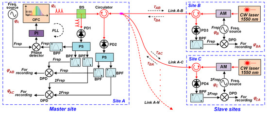
Figure 1.
Schematic of multiple-access time and frequency transfer based on OFC. OFC: optical frequency comb, CW: continuous wave, AM: amplitude modulation, PI: proportional integral controller, PD: photodetector, BS: beam splitter, PS: power splitter, BPF: band-pass filter, DPD: digital phase discriminator.
In our scheme, the light source of master site A is a femtosecond OFC, assuming that its repetition frequency is Frep and the initial phase is φA. The pulsed laser generated by the OFC passes through an optical beam splitter (BS) and outputs one part to the photodetector PD1 to generate an electrical signal with Frep. We use a phase-locking technique to lock the repetition frequency signal to an external reference signal, thus achieving the stability of the femtosecond OFC [38]. At the same time, the other part from the optical beam splitter is passed through a circulator and an optical coupler to output multiple optical signals. Each optical signal can be disseminated to each slave site through an optical link (optical fiber or free space). To facilitate the explanation of the scheme, Figure 1 shows the situation where the multiple-access time and frequency transfer is realized between master site A and two slave sites, B and C. In the actual system, more slave sites can be designed. At slave sites B and C, each has a CW laser as its light source. The frequencies of RF signals transmitted by the slave sites have been carefully designed while corresponding to the repetition frequency and harmonic frequencies of the OFC in the master site. As shown in the figure, the frequency of site B is the repetition frequency Frep, and the initial phase is φB. The frequency of site C is the second harmonic of the repetition frequency 2Frep, and the initial phase is φC. Sites B and C modulate the frequency signals to the lasers through the electro-optic modulator (EOM) and then enter the optical link after passing through the circulator. After the modulated laser signal reaches master site A, it is sent to the photodetector PD2 through the circulator. The optical signal output by PD2 obtains the electrical signal with the frequencies of Frep and 2Frep transmitted from slave sites B and C. At the same time, slave sites B and C will output the optical pulse signal sent from master site A to photodetectors PD3 and PD4, respectively, through the circulators and use the filter to extract the pure electrical signal with the frequencies of Frep and 2Frep. Next, the phase comparison of the signals received by each site is performed to obtain the two-way difference value so as to realize the two-way time and frequency transfer between master site A and slave site B and between master site A and slave site C.
At master site A, the signal output by PD1 can be filtered to obtain the local electrical signals with frequencies of Frep and 2Frep. Here, we have two signals with the same frequency of Frep, and next they are digitally phase-compared to obtain the phase difference φAB between the time–frequency reference signal of master site A and the time–frequency signal sent from slave site B. We also have two signals with the same frequency of 2Frep, which are digitally phase-compared to obtain the phase difference φAC between the time–frequency reference signal of master site A and the time–frequency signal sent from slave site C. At the same time, at slave site B, the two signals with the same frequency of Frep are digitally phase-compared to obtain the phase differences φBA between the local time–frequency reference signals of slave station B and the time–frequency signal sent from master station A. At slave site C, two signals with the same frequency of 2Frep are digitally phase-compared to obtain the phase differences φCA between the local time–frequency reference signals of slave station C and the time–frequency signal sent from master station A.
The timing diagram of the multiple-access time and frequency transfer is shown in Figure 2. The calculation of the two-way time–frequency comparison of the three sites is performed as follows. For transfer between sites A and B, we assume that the phase difference between sites A and B is ΔφAB. τAB and τBA are the timing delays of the laser beams from site A to B and site B to A in the fiber and freespace link, respectively. τTA and τRA are the fixed transmitting timing delay and receiving timing delay caused by the transmission link on site A, respectively. τTB and τRB are the fixed transmitting timing delay and receiving timing delay caused by the transmission link on site B, respectively. Similarly, for transfer between sites A and C, we assume that the phase difference between sites A and C is ΔφAC. τAC and τCA are the timing delays of the laser beams from site A to C and site C to A in the fiber and free-space link, respectively. τTC and τRC are the fixed transmitting timing delay and receiving timing delay caused by the transmission link on site C, respectively.
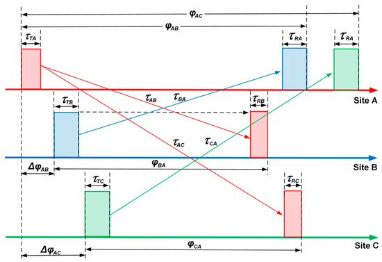
Figure 2.
Timing diagram of the multiple-access time and frequency transfer for one master site A and two slave sites B and C.
Considering the relations of the abovementioned timing differences, for sites A and B, φAB and φBA are written as follows.
Based on Equations (1) and (2), the relative phase difference between sites A and B can be calculated by
where φAB and φBA can be measured by a phase discriminator. τAB and τBA are identical as the two-way links are reciprocal. The other two fixed terms, (τTB − τRB) and (τRA − τTA), can be calibrated by a high-precision counter. Finally, ΔφAB can be calculated to determine the real timing difference between sites A and B. For sites A and C, the calculation is almost the same. φAC and φCA are written as follows.
Based on Equations (4) and (5), the relative phase difference between sites A and B can be calculated by
where φAC and φCA can be measured by a phase discriminator. τAC and τCA are identical as the two-way links are reciprocal. The other two fixed terms, (τTC − τRC) and (τRA − τTA), can be calibrated by a high-precision counter. Finally, ΔφAC can be calculated to determine the real timing difference between sites A and C. In this paper, Figure 1 only shows the case of two slave sites, and the schematic diagram can be easily extended to the scenario of N slave sites. The number of slave sites N is mainly constrained by the following parameters, including the repetition rate of femtosecond lasers and the bandwidth of photodetectors. In this experiment, the repetition frequency of the laser is 100 MHz, and the bandwidth of the photodetector is 10 GHz; the theoretical number of slave sites supported by this system is 100. To increase the number of slave sites, it is possible to consider reducing the repetition frequency of the laser and increasing the bandwidth of the photodetector. Of course, the parameters in practical application still need to be considered based on the actual number of slave sites.
3. Experimental Setup
In order to verify the performance of this scheme, we built an experiment of actual multiple-access time and frequency transfer over fiber and free-space links based on a femtosecond OFC, as shown in Figure 3. The experimental setup was designed with a master site, A, and two slave sites, B and C. All sites were placed at the same local end, and a rubidium atomic clock provided the reference source. At the far end, we designed a flat mirror to realize the light reflection between the master and the slave sites to form an optical link. The optical comb source of site A is an erbium-doped fiber femtosecond laser with a repetition frequency of 100 MHz, with a center wavelength of 1550 nm, power of ~60 mW, and pulse width of ~200 fs [30]. After the optical signal passes through an optical coupler (OC), one of the low-power signals is extracted through PD1, power splitter (PS), and BFP to obtain a repetition frequency 100 MHz signal. This signal is phase-detected with the 100 MHz signal synthesized by the rubidium atomic clock (FE-5680A, FEI Communications, Mitchel Field, NY, USA) in a mixer. After the phase error is generated, it is fed back to the laser through a proportional integral (PI) controller to form a phase-locked loop to achieve the stabilization of the OFC. The high-power signal output by OC enters the 3.9 km long optical fiber through a circulator, and then another OC outputs two optical signals of equal power, which are sent to free space through two collimators (CMs) and two telescopes. The two spatial lights reach sites B and C, respectively, after being reflected by the remote mirror. The distance of the entire free-space link is about 100 m. At sites B and C, the pulse optical signal transmitted by site A is collected by a CM and sent to PD3 and PD4 through a circulator, and the electrical signal containing repetition frequency and 2nd harmonic frequency is output. At site B, the signal output by PD3 passes through a BPF and an amplifier (AMP) to obtain a 100 MHz signal; at site C, the signal output by PD4 passes through a BPF and AMP to obtain a 200 MHz signal. At this point, the process of transmitting RF signals from the master site to each slave site is realized.
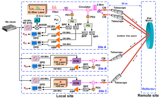
Figure 3.
Experimental setup of the multiple-access time and frequency transfer over a fiber and free-space link. OC: optical coupler, EOM: electro-optical modulator, PD: photodetector, CM: collimator, PS: power splitter, BPF: band-pass filter, AMP: amplifier, DPD: digital phase discriminator.
The light sources of sites B and C are two CW lasers with a wavelength of 1550 nm, output power of ~20 mW, and linewidth of ~3 MHz. The time and frequency source of site B is a 100 MHz signal synthesized by the rubidium atomic clock. The 100 MHz electrical signal is modulated onto the light through an amplitude modulation EOM and then sent to the free-space link through a circulator and a CM. The time and frequency source of site C is a 200 MHz signal synthesized by the rubidium atomic clock. The 200 MHz electrical signal is also modulated onto the light through another amplitude modulation EOM and then sent to the free-space link through a circulator and a CM. As shown in Figure 3, the two optical signals arrive at site A along the same optical path mentioned above, are collected by two CMs, combined at the OC, passed through the 4 km optical fiber, and converted into an electrical signal by the circulator and PD2. It should be pointed out that the electrical signal contains both 100 MHz and 200 MHz RF signals sent simultaneously by sites B and C. It is divided into two electrical signals through a PS and then passed through two BPFs, respectively. Finally, two single-frequency 100 MHz and 200 MHz signals are extracted.
In order to obtain the time–frequency difference of site A, the electrical signal output by PD1 passes through a PS and two BPFs to obtain two reference signals (with frequencies of 100 MHz and 200 MHz, respectively). The phase difference between the reference 100 MHz signal and the 100 MHz signal received from site B is measured using a digital phase detector (DPD) to obtain the phase difference value φAB. At the same time, the phase difference between the reference 200 MHz signal and the 200 MHz signal received from site B is also measured by another DPD to obtain the phase difference value φAC. In order to obtain the time–frequency difference value of stations B and C, the DPD is used to measure the phase difference between the synthesized 100 MHz signal and the 100 MHz signal received from station A at station B, and the phase difference value φBA is obtained; at the same time, at site C, the DPD is used to measure the phase difference between the synthesized 200 MHz signal and the 200 MHz signal received from site A, and the phase difference value φCA is obtained. Through the calculation described in the previous section, we can obtain the relative phase difference between sites A and B, and between sites A and C. So far, we have realized multiple-access time and frequency transfer based on the two-way phase comparison between the master site and the two slave sites.
4. Experimental Results
The multiple-access time and frequency transfer experiment was conducted in the Innovation Center of our campus, and the experiment lasted about 10,000 s. Figure 4a shows the result of time and frequency transfer between sites A and B. Curve i is the phase difference φAB between the reference signal of site A and the time–frequency signal sent from site B to A. Curve ii is the phase difference φBA between the reference signal of site B and the time–frequency signal sent from site A to B. Curve iii is the relative phase difference between site A and B calculated by the φAB and φBA, based on the two-way time and frequency comparison, without calculation of the fixed phase delay. Here, it can be treated as the estimated time and frequency transfer result between A and B, and the RMS timing fluctuation is 119 ps. Figure 4b shows the result of time and frequency transfer between sites A and C. Curve i is the phase difference φAC between the reference signal of site A and the time–frequency signal sent from site C to A. Curve ii is the phase difference φCA between the reference signal of site B and the time–frequency signal sent from site A to C. Curve iii is the relative phase difference between site A and C calculated by the φAC and φCA, based on the two-way time and frequency comparison, without calculation of the fixed phase delay either. Here, it can also be treated as the estimated time and frequency transfer result between A and C, and the RMS timing fluctuation is 59.5 ps.
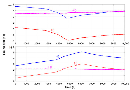
Figure 4.
Time fluctuation results of the multiple-access time and frequency transfer. (a) Transfer between site A and B; (b) transfer between site A and C.
The stability of the time and frequency transfer can be calculated from the phase difference measurement results, generally using the Allan Deviation, whose physical mechanism refers to the RMS value of the timing signal difference measured by the band-pass filter within a given integration time interval [1]. Curves i and ii in Figure 5 represent the frequency transfer stability which is calculated as overlapping Allan Deviation, between sites A and B, and between sites A and C, respectively. As we can see from Figure 5, the stability of the time and frequency transfer between A and B is 3.3 × 10⁻¹¹ at 1 s and 2.8 × 10⁻¹⁴ at 2000 s. The stability of the time–frequency transfer between A and C is 3.0 × 10⁻¹¹ at 1 s and 2.6 × 10⁻¹⁴ at 2000 s. The two-way time–frequency comparison method in this scheme can effectively reduce the impact of temperature and other factors on the long-term stability of the optical fiber and free-space transmission link, thereby improving the long-term stability of time–frequency transfer.
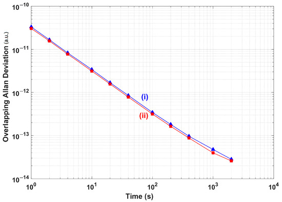
Figure 5.
Stability results of the multiple-access time and frequency transfer.
This experimental setup realizes the simultaneous time and frequency transfer between one master site and two slave sites. The scheme can also be extended to more slave site scenarios. The reference source of the slave site only needs to select the harmonic frequency of the master OFC. The key advantage of this scheme is that the light source of the master site only uses one femtosecond OFC, and there is only one photodetector for receiving the optical signal of the slave sites. This single light source and single receiving photodetector can greatly improve the efficiency of multiple-channel time and frequency phase difference measurements in this system, reduce the complexity, and reduce the cost, which provides important support for building a large-scale multiple-access time and frequency transfer system.
5. Conclusions
In this paper, we propose a multiple-access fiber and free-space time and frequency transfer technique. This technique uses a two-way time–frequency comparison between the femtosecond OFC and CW lasers to achieve high-precision, real-time time and frequency transfer between the master site and multiple slave sites. Based on this transfer technique, we have built a multiple-access time and frequency fiber and free-space transfer experiment, which includes a master and two slave sites. The transmission distance between the master and each slave site is about 3.9 km in optical fiber plus 100 m in free space. The experimental results show that the RMS timing fluctuation of the time and frequency transfer between master site A and slave site B is 119 ps, with a frequency stability of 3.3 × 10⁻¹¹ at 1 s and 2.8 × 10⁻¹⁴ at 2000 s. The RMS timing fluctuation of the time and frequency transfer between master site A and slave site C is 59.5 ps, with a frequency stability of 3.0 × 10⁻¹¹ at 1 s and 2.6 × 10⁻¹⁴ at 2000 s. This technique uses the characteristics of the frequencies of the slave sites being the same as the harmonic frequencies of the OFC and adopts a single light source and a single receiving detector design in the master site, which improves the system reliability and greatly reduces the system complexity and cost. It can be applied to the construction of large-scale multiple-access time and frequency synchronization networks in the future.
Author Contributions
Conceptualization, D.H.; methodology, W.H. and P.Z.; software, P.Z.; hardware, P.Z.; investigation, W.H.; data curation, W.H.; writing—original draft preparation, W.H. and D.H.; writing—review and editing, W.H., P.Z., and D.H.; supervision, D.H.; project administration, D.H.; funding acquisition, W.H. and D.H. W.H. is the first author of the article. D.H. is the corresponding author of the article. All authors have read and agreed to the published version of the manuscript.
Funding
This study was funded by the National Natural Science Foundation of China, grant number 62271109, the Natural Science Foundation of Sichuan Province of China (No. 2023NSFSC0445), and the State Key Laboratory of Advanced Optical Communication Systems and Networks (2023GZKF09), China.
Institutional Review Board Statement
Not applicable.
Informed Consent Statement
Not applicable.
Data Availability Statement
Data are contained within the article.
Conflicts of Interest
The authors declare no conflicts of interest.
References
- Levine, J. A review of time and frequency transfer methods. Metrologia 2008, 45, 162–174. [Google Scholar] [CrossRef]
- Predehl, K.; Grosche, G.; Raupach, S.M.F.; Droste, S.; Terra, O.; Alnis, J.; Legero, T.; Hansch, T.W.; Udem, T.; Holzwarth, R.; et al. A 920-Kilometer Optical Fiber Link for Frequency Metrology at the 19th Decimal Place. Science 2012, 336, 441–444. [Google Scholar] [CrossRef] [PubMed]
- He, Y.; Baldwin, K.G.H.; Orr, B.J.; Warrington, R.B.; Wouters, M.J.; Luiten, A.N.; Mirtschin, D.P.; Tzioumis, T.; Phillips, C.; Stevens, J.; et al. Long-distance telecom-fiber transfer of a radio-frequency reference for radio astronomy. Optica 2018, 5, 138–146. [Google Scholar] [CrossRef]
- Li, B.H.; Rizos, C.; Lee, H.K.; Lee, H.K. A GPS-slaved time synchronization system for hybrid navigation. GPS Solut. 2006, 10, 207–217. [Google Scholar] [CrossRef]
- Guo, G.; Li, C.; Hou, D.; Liu, K.; Sun, F.; Zhang, S. Analysis and Implementation of a Frequency Synthesizer Based on Dual Phase-Locked Loops in Cesium Atomic Clock. Appl. Sci. 2013, 13, 9155. [Google Scholar] [CrossRef]
- Tsao, S.; Yu, H.; Lin, Y. Analysis of an optical satellite communication system with stabilized microwave reference note transmission. Microw. Opt. Technol. Lett. 2002, 33, 149–151. [Google Scholar] [CrossRef]
- Zhang, H.; Dai, G. Design of optical fiber communication network monitoring and detection system based on address resolution protocol cheats. Optik 2016, 127, 11242–11249. [Google Scholar] [CrossRef]
- Asanee, S.; Ramesh, A. Ultra-High-Speed Multichannel Data Transmission Using Hybrid Substrate Integrated Waveguides. IEEE Trans. Microwave Theory Tech. 2008, 56, 1973–1984. [Google Scholar]
- Kim, J.; Cox, J.A.; Chen, J.; Kärtner, F.X. Drift-free femtosecond timing synchronization of remote optical and microwave sources. Nat. Photon. 2008, 2, 733–736. [Google Scholar] [CrossRef]
- Musha, M.; Hong, F.L.; Nakagawa, K.; Ueda, K. Coherent optical frequency transfer over 50-km physical distance using a 120-km-long installed telecom fiber network. Opt. Express 2008, 16, 16459–16466. [Google Scholar] [CrossRef]
- Williams, P.A.; Swann, W.C.; Newbury, N.R. High-stability transfer of an optical frequency over long fiber-optic links. J. Opt. Soc. Am. B 2008, 25, 1284–1293. [Google Scholar] [CrossRef]
- Jiang, H.; Kefelian, F.; Crane, S.; Lopez, O.; Lours, M.; Millo, J.; Holleville, D.; Lemonde, P.; Chardonnet, C.; Amy-Klein, A.; et al. Long-distance frequency transfer over an urban fiber link using optical phase stabilization. J. Opt. Soc. Am. B 2008, 25, 2029–2035. [Google Scholar] [CrossRef]
- Grosche, G.; Terra, O.; Predehl, K.; Holzwarth, R.; Lipphardt, B.; Vogt, F.; Sterr, U.; Schnatz, H. Optical frequency transfer via 146 km fiber link with 10-19 relative accuracy. Opt. Lett. 2009, 34, 2270–2272. [Google Scholar] [CrossRef] [PubMed]
- Daussy, C.; Lopez, O.; Amy-Klein, A.; Goncharov, A.; Guinet, M.; Chardonnet, C.; Narbonneau, F.; Lours, M.; Chambon, D.; Bize, S.; et al. Long-distance frequency dissemination with a resolution of 10–17. Phys. Rev. E 2005, 94, 203904. [Google Scholar]
- Chen, Y.F.; Jiang, J.; Jones, D.J. Remote distribution of a mode-locked pulse train with sub 40-as jitter. Opt. Express 2006, 14, 12134–12144. [Google Scholar] [CrossRef]
- Lopez, O.; Amy-Klein, A.; Daussy, C.; Chardonnet, C.; Narbonneau, F.; Lours, M.; Santarelli, G. 86-km optical link with a resolution of 2 x 10-18 for RF frequency transfer. Eur. Phys. J. D 2008, 48, 35–41. [Google Scholar] [CrossRef]
- Kumagai, M.; Fujieda, M.; Nagano, S.; Hosokawa, M. Stable radio frequency transfer in 114 km urban optical fiber link. Opt. Lett. 2009, 34, 2949–2951. [Google Scholar] [CrossRef]
- Lenihan, A.S.; Sinkin, O.V.; Marks, B.S.; Tudury, G.E.; Runser, R.J.; Goldman, A.; Menyuk, C.R.; Carter, G.M. Nonlinear timing jitter in an installed fiber network with balanced dispersion compensation. IEEE Photonics Technol. Lett. 2005, 17, 1558–1560. [Google Scholar] [CrossRef][Green Version]
- Hou, D.; Li, P.; Liu, C.; Zhao, J.; Zhang, Z. Long-term stable frequency transfer over an urban fiber link using microwave phase stabilization. Opt. Express 2011, 19, 506–511. [Google Scholar] [CrossRef]
- Kim, J.; Chen, J.; Zhang, Z.; Wong, F.N.C.; Kärtner, F.X.; Loehl, F.; Schlarb, H. Long-term femtosecond timing link stabilization using a single-crystal balanced cross correlator. Opt. Lett. 2007, 32, 1044–1046. [Google Scholar] [CrossRef]
- Holman, K.W.; Jones, D.J.; Hudson, D.D.; Ye, J. Precise frequency transfer through a fiber network by use of 1.5-mu m mode-locked sources. Opt. Lett. 2004, 29, 1554–1556. [Google Scholar] [CrossRef] [PubMed]
- Holman, K.W.; Hudson, D.D.; Ye, J.; Jones, D.J. Remote transfer of a high-stability and ultralow-jitter timing signal. Opt. Lett. 2005, 30, 1225–1227. [Google Scholar] [CrossRef] [PubMed]
- Deschenes, J.D.; Sinclair, L.C.; Giorgetta, F.R.; Swann, W.C.; Baumann, E.; Bergeron, H.; Cermak, M.; Coddington, I.; Newburry, N.R. Synchronization of distant optical clocks at the femtosecond level. Phys. Rev. X 2016, 6, 021016. [Google Scholar] [CrossRef]
- Wang, B.; Gao, C.; Chen, W.; Miao, J.; Wang, L. Precise and continuous time and frequency synchronisation at the 5 × 10⁻¹⁹ accuracy level. Sci. Rep. 2012, 2, 556. [Google Scholar] [CrossRef] [PubMed]
- Foreman, S.M.; Holman, K.W.; Hudson, D.D.; Jones, D.J.; Ye, J. Remote transfer of ultrastable frequency references via fiber networks. Rev. Sci. Instrum. 2007, 78, 021101. [Google Scholar] [CrossRef]
- Lanziano, L.; Sherf, I.; Malka, D. A 1 × 8 Optical Splitter Based on Polycarbonate Multicore Polymer Optical Fibers. Sensors 2024, 24, 5063. [Google Scholar] [CrossRef]
- Gelkop, B.; Aichnboim, L.; Malka, D. RGB wavelength multiplexer based on polycarbonate multicore polymer optical fiber. Opt. Fiber Technol. 2021, 61, 102441. [Google Scholar] [CrossRef]
- Tatarskii, V.I. Wave Propagation in a Turbulent Medium; McGraw-Hall: New York, NY, USA, 1961. [Google Scholar]
- Zuev, V.E.; Zemlianov, A.A.; Kopytin, I.D. Nonlinear Optics of the Atmosphere; HMI: Saint Petersburg, Russia, 1989. [Google Scholar]
- Zhang, D.; Chen, J.; Li, Y.; Hou, D. Free-space-based multiple-access frequency transfer based on optical frequency comb. In Frontier Research and Innovation in Optoelectronics Technology and Industry; Habib, K., Lewis, E., Eds.; CRC (Taylor & Francis G.): London, UK, 2018. [Google Scholar]
- Glushkov, A.V. Multiphoton spectroscopy of atoms and nuclei in a laser field: Relativistic energy approach and radiation atomic lines moments method. Adv. Quant. Chem. 2019, 78, 253–285. [Google Scholar]
- Farell, T.C. The effect of atmospheric optical turbulence on laser communications systems: Part 1, theory. In Proceedings of the SPIE 11017, Sensors and Systems for Space Applications XII, Baltimore, MD, USA, 14–18 April 2019; 110170B. [Google Scholar]
- Khetselius, O.Y.; Glushkov, A.V.; Stepanenko, S.M.; Svinarenko, A.A.; Buyadzhi, V.V. Advanced Quantum-Kinetic Model of Energy Exchange in Atmospheric Molecule Mixtures and CO2 Laser-Molecule Interaction. In Advances in Methods and Applications of Quantum Systems in Chemistry, Physics, and Biology; Progress in Theoretical Chemistry and Physics; Springer: Cham, Switzerland, 2021; Volume 33, pp. 207–216. [Google Scholar]
- Gao, C.; Wang, B.; Chen, W.; Bai, Y.; Miao, J.; Zhu, X.; Li, T.; Wang, L. Fiber-based multiple-access ultrastable frequency dissemination. Opt. Lett. 2012, 37, 4690–4692. [Google Scholar] [CrossRef]
- Wang, B.; Zhu, X.; Gao, C.; Bai, Y.; Dong, J.; Wang, L. Square kilometre array telescope—Precision reference frequency synchronisation via 1f-2f dissemination. Sci. Rep. 2015, 5, 13851. [Google Scholar] [CrossRef]
- Hou, D.; Zhang, D.; Sun, F.; Li, Y.; Tian, J. Free-space-based multiple-access frequency dissemination with optical frequency comb. Opt. Express 2018, 26, 19199–19205. [Google Scholar] [CrossRef] [PubMed]
- Ren, J.; Hou, D.; Gao, Y.; Guo, G.; Liu, K. Highly stable multiple-access underwater frequency transfer with terminal phase compensation. Opt. Lett. 2021, 46, 4745–4748. [Google Scholar] [CrossRef] [PubMed]
- Hou, D.; Wu, J.; Ren, Q.; Zhao, J. Analysis of long-term phase-locking technique for mode-locked laser with pid regulator. IEEE J. Quantum Electron. 2012, 48, 839–846. [Google Scholar] [CrossRef]
Disclaimer/Publisher’s Note: The statements, opinions and data contained in all publications are solely those of the individual author(s) and contributor(s) and not of MDPI and/or the editor(s). MDPI and/or the editor(s) disclaim responsibility for any injury to people or property resulting from any ideas, methods, instructions or products referred to in the content. |
© 2024 by the authors. Licensee MDPI, Basel, Switzerland. This article is an open access article distributed under the terms and conditions of the Creative Commons Attribution (CC BY) license (https://creativecommons.org/licenses/by/4.0/).