Article

Influence of Connecting Cables on Stator Winding Overvoltage Distribution under High-Frequency Pulse Width Modulation

1
Beijing Goldwind Science and Technology Innovation Wind Power Equipment Co., Ltd., Beijing 100176, China
2
School of Electrical Engineering, Beijing Jiaotong University, Beijing 100044, China
*
Author to whom correspondence should be addressed.
Appl. Sci. 2024, 14(20), 9220; https://doi.org/10.3390/app14209220
Submission received: 7 July 2024 / Revised: 9 September 2024 / Accepted: 18 September 2024 / Published: 11 October 2024
(This article belongs to the Section Electrical, Electronics and Communications Engineering)

Abstract

:
In the variable frequency motor drive system, because the cable impedance does not match the motor impedance, the reflection wave of the voltage wave will be generated. The superposition of reflected voltage waves can lead to overvoltage at the motor ends, which can damage the insulation structure. In this paper, the equivalent circuit models of cable and stator winding are established, respectively. The overvoltage distribution under different power supply frequencies and cable lengths is simulated and analyzed. The influence mechanism of power supply frequency and cable length on the overvoltage distribution of stator winding are studied. The simulation results show that the overvoltage of the first pulse falling edge will be superimposed on the overvoltage of the second pulse rising edge under high-frequency conditions, resulting in a further increase in the overvoltage. The voltage appears in all coils after the middle of the winding. The ground voltage is up to 1.32 times the input voltage, and the inter-turn voltage is up to 9.2 times the average voltage. The increase in cable length will lead to an increase in ground voltage, but the increase in speed will slow down after exceeding the critical length of 300 m. The maximum ground voltage can reach 1.93 times of the input voltage, which is 3.6% different from the calculation result under ideal conditions. The inter-turn voltage changes with the cable length in an N-shaped manner, up to 185 V. The results of this paper are of great significance to further study the insulation design of generator end input.

1. Introduction

In recent years, wind energy has become one of the most important renewable energy sources in the world, and many countries are vigorously developing wind power generation [1]. As the core equipment of wind power generation, the operation and maintenance of wind turbine generators have attracted much attention; however, the life of wind turbine generators in actual operation is much smaller than the design life, which is because the insulation of inverter motors always fails prematurely [2,3,4]. The cause of the failure has been shown to be the use of Pulse Width Modulation (PWM) technology after much research and practice [5]. At low frequencies, the length of the cable is so different from the wavelength of the voltage wave in the cable that the effect of the distribution parameters can be neglected. However, in high-frequency motor drive systems, the wavelength of the voltage wave decreases dramatically, and the length of the cable is non-negligible in comparison, so the effect of long cables must be considered. When the high-frequency PWM voltage pulse is transmitted to the motor terminal through a long cable, the PWM pulse generates high-frequency oscillations in the cable due to the characteristic impedance of the cable, resulting in overvoltage [6,7,8].
Scholars have focused their primary research attention on the effects of cable lengths. The effect of long cables on overvoltage at the motor end is mainly due to the process of voltage transmission in the cable. As the characteristic impedance of the cable is seriously mismatched with the impedance of the output end of the inverter and the equivalent impedance of the motor, this causes significant reflection of the voltage wave. The superposition of the reflected wave and the incident wave makes the motor end generate a huge overvoltage. Therefore, scholars have researched and analyzed the formation of voltage wave reflections in cables and the process of reflection transmission, explaining the principle of generating overvoltage at the motor end [9]. Ma Hongfei et al. found that the voltage at the motor terminals approximately doubles when the pulse is transmitted from the inverter to the motor for more than 1/3 of the time of the rising edge [10]. R. Ortega et al. found that the length of the cable under high-frequency pulses causes a delay in the wave propagation time, which further leads to overvoltage generation [11]. Li Lan et al. found that the overvoltage stops rising when the cable length reaches a critical value and calculated that the critical cable length is proportional to the PWM rising edge time [12]. G. Skibinski et al. proposed a reflected wave drive–cable–motor system model, and discussed the effect of distributed vs. transport delay-type models on modeling accuracy [13]. H. De Paula et al. further modeled the correct representation of cable parameters over a wide frequency range up to MHz [14]. Based on these models, Yu Guang constructed a theoretical calculation model of overvoltage at the motor end, and the error between the calculated overvoltage amplitude and the actual measured value is less than 10% [15]. Zhang Chenyu et al. proposed a way to divide the whole system into two parts by establishing the equivalent circuit at the front end of the motor; the inverter and the cable constitute the Davignan equivalent circuit, after which the motor end voltage is finally analyzed by obtaining the equivalent circuit at the motor end [16]. After modeling the connecting cables at the end of the motor, the scholars used software such as ANSYS to perform simulations to study the motor turn-to-turn distribution [17,18]. It was ultimately determined that the maximum voltage occurs at the first or last turn of the coil, depending on the motor construction. To suppress this overvoltage, scholars have proposed several methods. The first is series-parallel resistance or an RC filter, which suppresses the overvoltage effect obviously but with a large power loss [19]. The second method is filtering at the inverter end, but the design is complex and costly [20,21]. The third method is to use a better control strategy, which is more often used in power systems [22]. The last method is to realize the matching of cables to motors and inverters, which is the main purpose of this paper’s study of voltage distribution.
The effect of frequency on overvoltage has been less studied, and most scholars have used it as a condition for modeling and have not discussed it separately [23]. This paper is based on the two frequencies at which the motors actually produced by our company are often operated, as well as the frequencies under the high-frequency test. These three types of representative frequencies were analyzed to determine if the motor insulation was reasonably effective.
Based on the above background, this paper calculates the end voltage distribution of permanent magnet synchronous wind turbine stator windings under different pulse frequencies and different connecting cable lengths, respectively, and studies the rule of change and influencing factors, which provides a theoretical basis for insulation design.

2. Experimental Research and Analysis

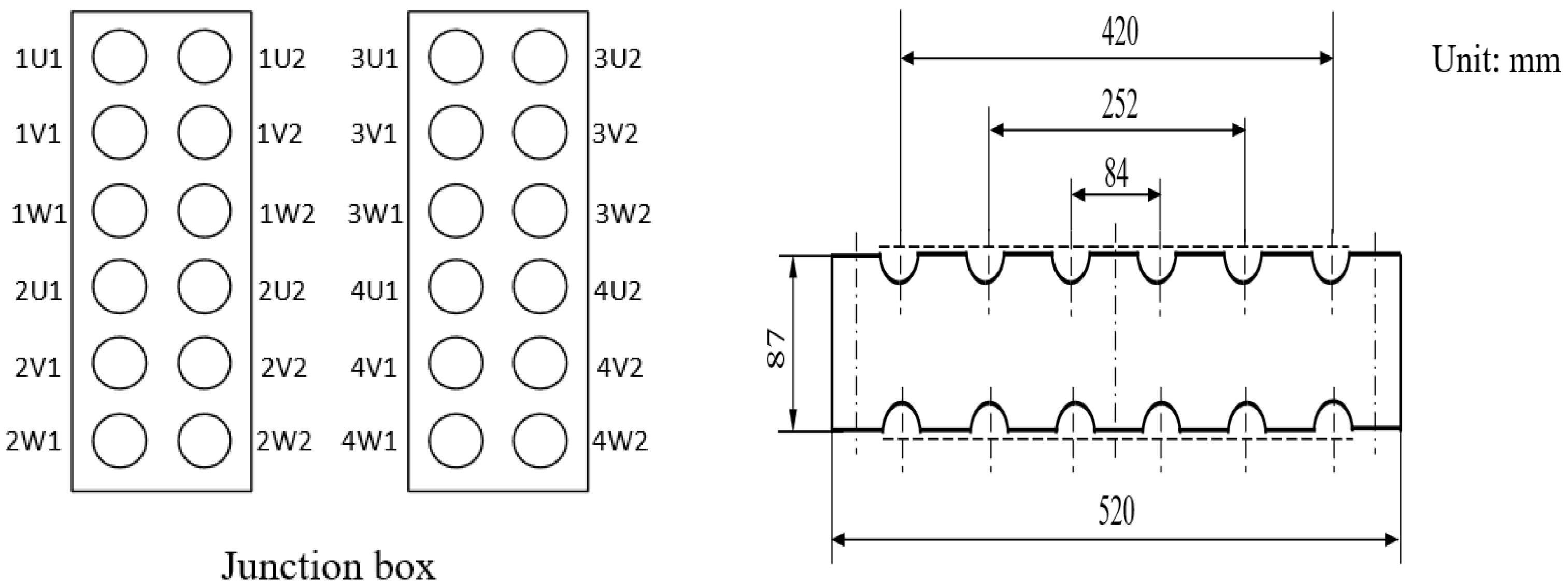
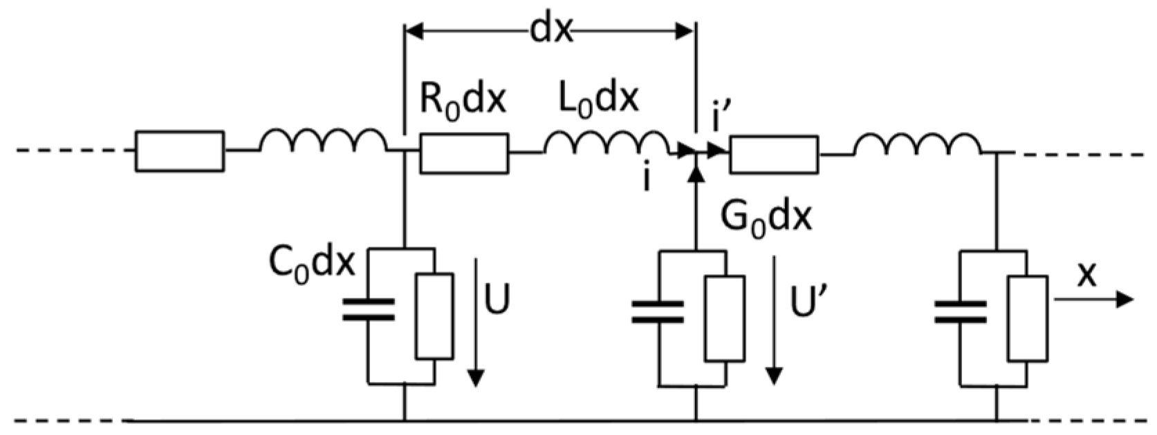
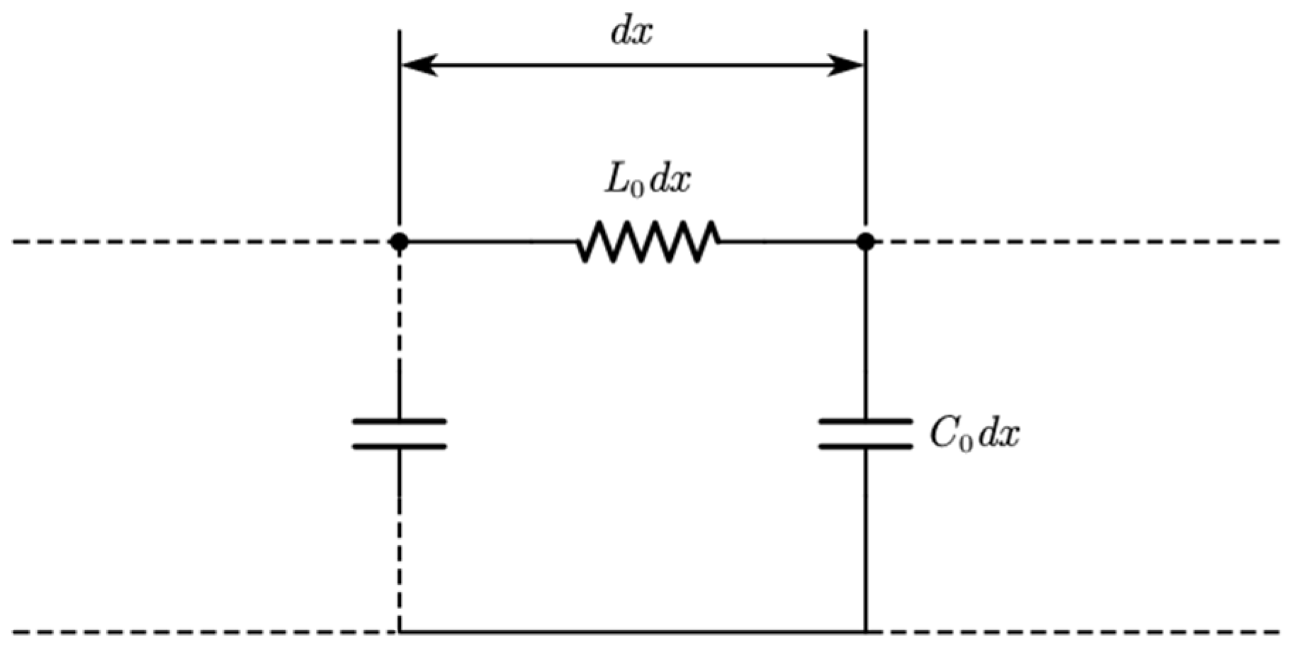
2.1. The Establishment of the End Connection Cable Model

In this paper, a single-core silicone rubber insulated cable with a cross-section of 240 mm2 is simulated and studied. The specific layout and structure size of the cable box connected to the end of the permanent magnet wind turbine are shown in Figure 1.
Figure 1 shows that there are two junction boxes: junction box 1 and junction box 2. Among them, 1U1 represents the first set of windings, the number of winding phases is the U (A) phase, and the first cable of this phase 1U2 is a cable in parallel with 1U1.
Under the action of a high-frequency PWM wave, the wavelength of the pulse wave λ = v / f is smaller than that of the fundamental frequency (v is the transmission speed of the voltage wave, f is the frequency of the voltage wave). When the output end of the inverter is connected to the motor by cable, the cable length cannot be ignored or compared with the voltage wavelength, and the distributed parameters of the cable must be considered. The equivalent circuit of single-phase cable is shown in Figure 2. Among them, R0 is the resistance of unit length wire, L0 is the inductance of unit length wire, G0 is the insulation resistance of unit length, and C0 is the capacitance of unit length wire to ground.
In the case of high frequency, due to R 0 ω L 0 ,     G 0 ω C 0 ,   R 0 and G 0 can be ignored and the uniform line can be regarded as a lossless line. For the lossless transmission line, the equivalent circuit diagram is shown in Figure 3:

2.2. Finite Element Calculation of Distribution Parameters of Permanent Magnet Motor End Cable

The solution of the distributed parameters of the three-phase cable mainly includes the distributed inductance of the cable, the ground capacitance of the cable, and the interphase capacitance between adjacent cables. The capacitance diagram of the three-phase cable is shown in Figure 4:
In Figure 4, Ca0, Cb0, and Cc0 represent the ground capacitance of A, B, and C, respectively, and Cab, Cbc, and Cac represent the interphase capacitance between AB, BC, and AC.
The length of the cable is set to 4 m, and the thickness of the outer insulation layer is 3 mm. To obtain the distributed capacitance, the electrostatic field solver of ANSYS EM is used. The finite element method is used to divide the solution domain, and the element analysis is carried out for each unit. Finally, the capacitance of A to ground is 17.0 pF, the capacitance between two cables in parallel is 28.4 pF, the capacitance between AB phases is 28.4 pF, and the capacitance between AC phases is 1.6 pF.
When calculating the distributed inductance, the electrostatic field solver of ANSYS EM is used to obtain the distributed inductance; the distributed inductance is 0.7 μH.

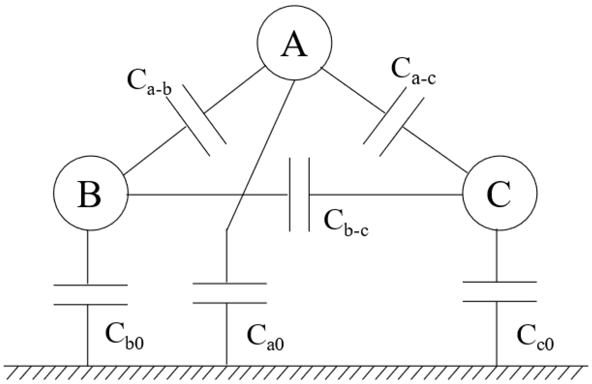
2.3. Distributed Parameters of Stator Winding of Permanent Magnet Machine

In this paper, a 6 MW permanent magnet synchronous wind generator is used as the simulation object. Its stator-rated voltage is 1380 V, the number of parallel branches is 6, the number of series coils is 4, and each coil has five turns. The equivalent circuit diagram is shown in Figure 5.
The winding equivalent resistance utilization Formula (1) calculation [24,25] is as follows:
R = 2 l d α δ σ
In the above formula, R is the winding conductor resistance; ld is the length of the conductor; α is the perimeter of the conductor cross-section; δ is the depth of skin; σ is the conductivity of copper. The calculated equivalent resistance of the single-turn coil is 0.26 Ω.
The distributed capacitance of the winding is calculated by finite element simulation. The results are shown in Table 1.
The equivalent inductance depends on the winding structure, permeability, and voltage frequency of the motor. The equivalent inductance is calculated by simulation as shown in Table 2 below.

3. Influence of PWM Pulse Frequency on Overvoltage Distribution

When studying the influence of input pulse frequency on overvoltage distribution, the influence of other conditions is ignored. For the input PWM pulse of the permanent magnet wind turbine, the pulse rising edge is set to 2 μs, the pulse amplitude is set to 2800 V, and the pulse width is set to 5 μs. The pulse voltage signals with frequencies of 100 kHz, 50 kHz, and 10 kHz are used as voltage sources to study the distribution characteristics of ground and inter-turn voltages of motor end windings at different frequencies.

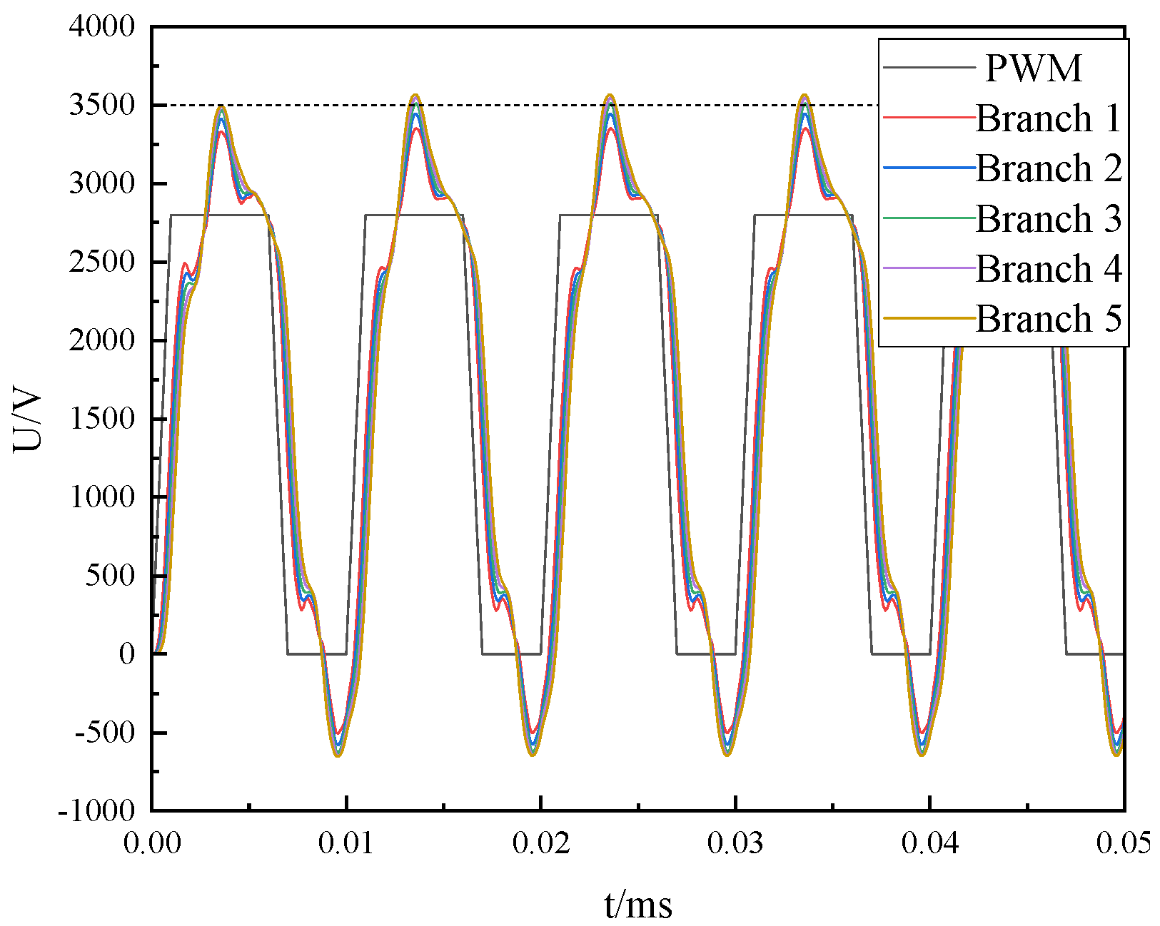
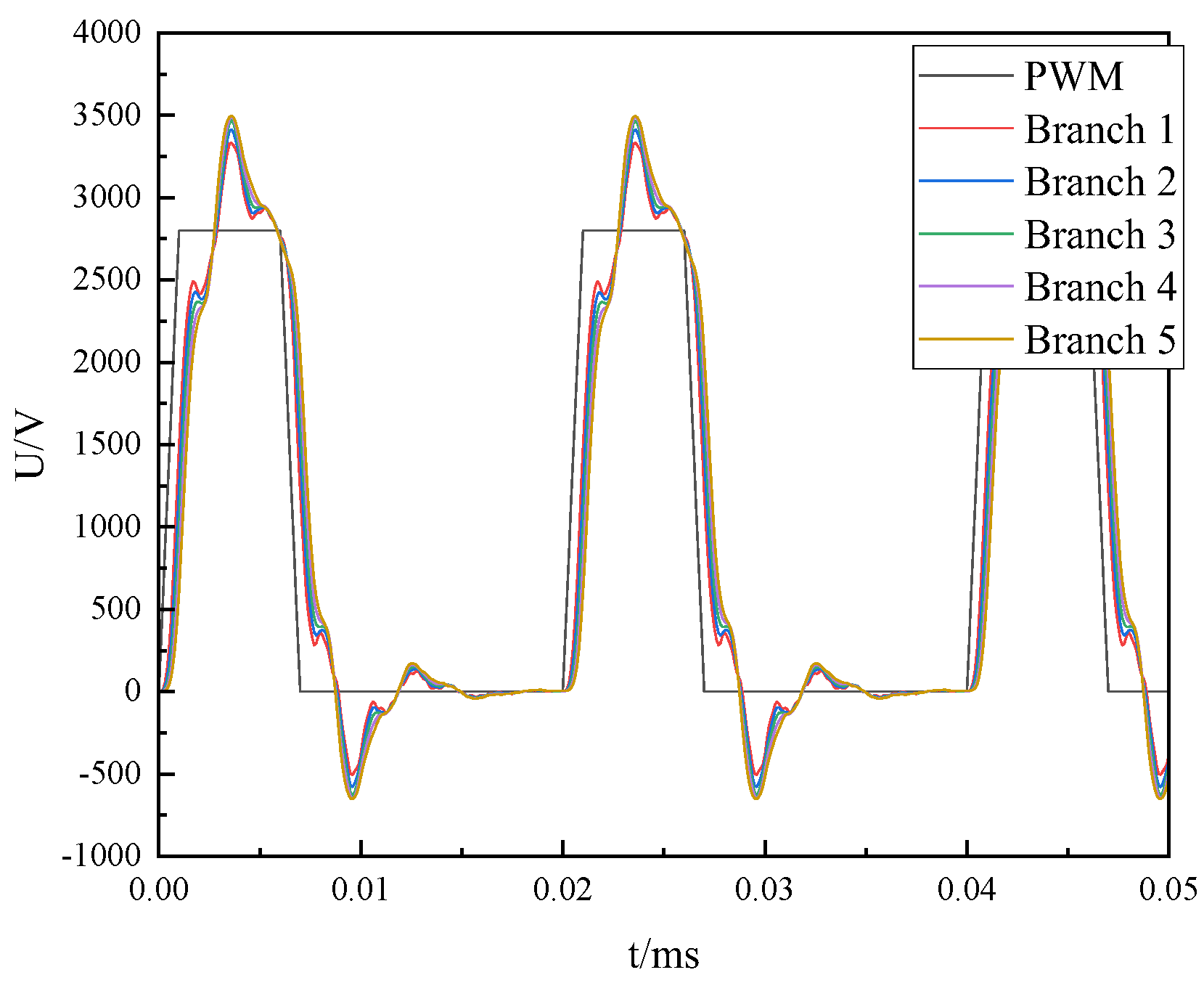
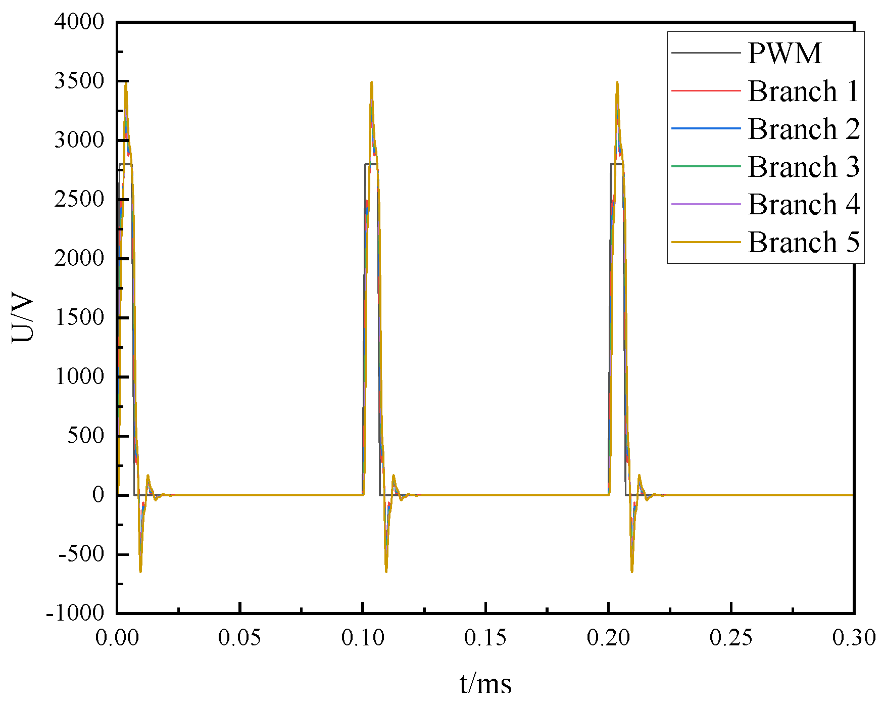
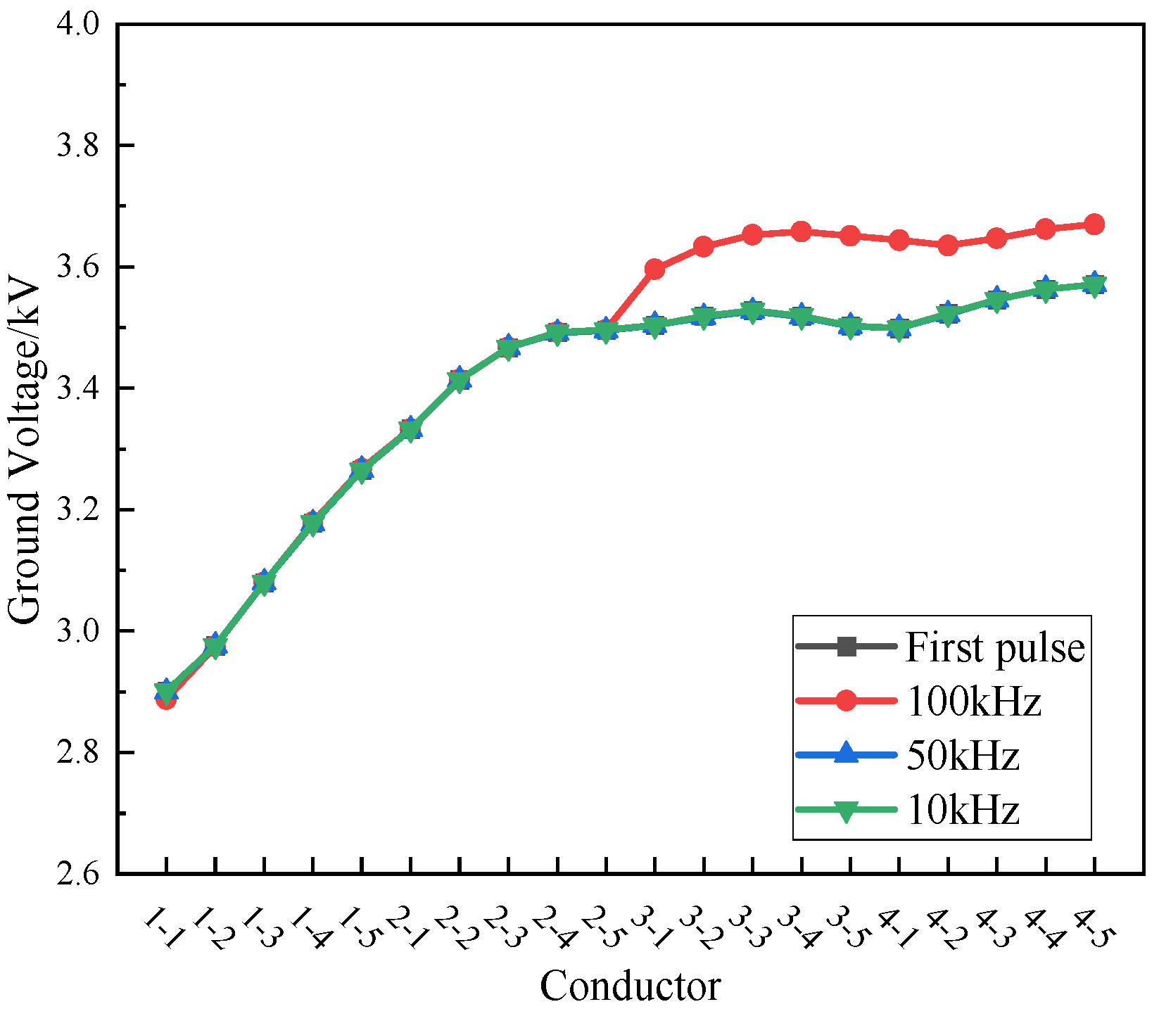
3.1. The Influence of PWM Frequency on the Voltage Distribution from the End to the Ground

The simulation waveform of the ground voltage of each turn conductor at 100 kHz frequency is shown in Figure 6.
It can be seen from the above figure that the maximum voltage of the second pulse wave is higher than that of the first pulse voltage wave, and the maximum ground voltage will not continue to rise later. This is because when the frequency is high, the overvoltage generated by the falling edge of the first pulse wave is too late to attenuate to zero, so it will be generated at the rising edge of the second pulse wave. The superposition of the overvoltage generated by the second pulse wave leads to a further increase in the ground voltage. When the third pulse wave comes, the overvoltage generated by the falling edge of the first pulse wave attenuates to zero, only affected by the overvoltage generated by the falling edge of the second pulse wave, so the maximum voltage remains unchanged.
When the frequency drops to 50 kHz, the ground voltage simulation waveform of each turn conductor is shown in Figure 7.
As shown in Figure 7, when the frequency drops to 50 kHz, the first pulse’s rising edge overvoltage is the same, and the first pulse wave’s falling edge overvoltage is greatly attenuated, resulting in the second pulse wave’s rising edge overvoltage being lower than that at 100 kHz.
When the frequency is further reduced to 10 kHz, the simulation waveform is shown in Figure 8.
As shown in Figure 8, when the frequency drops to 10 kHz, the first pulse overvoltage is still basically the same, but the pulse wave at the falling edge is completely attenuated, which has little effect on the second rising edge pulse wave. The waveform generated by the first pulse is consistent with the waveform generated by the second pulse.
In summary, the first pulse wave rising edge overvoltage waveform at each frequency is the same; the difference is in the second pulse wave overvoltage waveform, and as the frequency decreases, that is, the period increases, the second pulse’s generated overvoltage will be reduced. The second pulse wave rising edge overvoltage of three frequencies is compared with the first pulse wave rising edge overvoltage, as shown in Figure 9.
As shown in Figure 9, the first pulse (black) in the figure represents the overvoltage generated by the first pulse wave at different frequencies; 1–1~4–5 denotes the first turn conductor of coil 1 to the fifth turn conductor of coil 4. The overvoltage generated by the first pulse wave at different frequencies is the same; the maximum is 3.6 kV, which is about 1.3 times of the input voltage and is located at the end coil. When the frequency is 100 kHz, the voltage of the conductor to the ground is superimposed from the middle coil to the end coil, that is, the first pulse wave falling edge overvoltage is not attenuated completely and the second pulse wave rising edge overvoltage is superimposed. At this time, the pulse rising edge overvoltage is up to 3.7 kV, which is located at the last turn of the end coil.
With the decrease in pulse frequency, the influence of the first pulse wave’s falling edge overvoltage on the second pulse wave’s rising edge overvoltage gets smaller and smaller, which makes the second pulse wave’s rising edge to the ground voltage distribution closer and closer to the overvoltage distribution generated by the first pulse wave. In the case of 10 kHz and 50 kHz, the second pulse wave rising edge overvoltage is the same as the first pulse wave rising edge overvoltage. The maximum ground voltage is 3.6 kV, which is located at the last turn of the end coil.

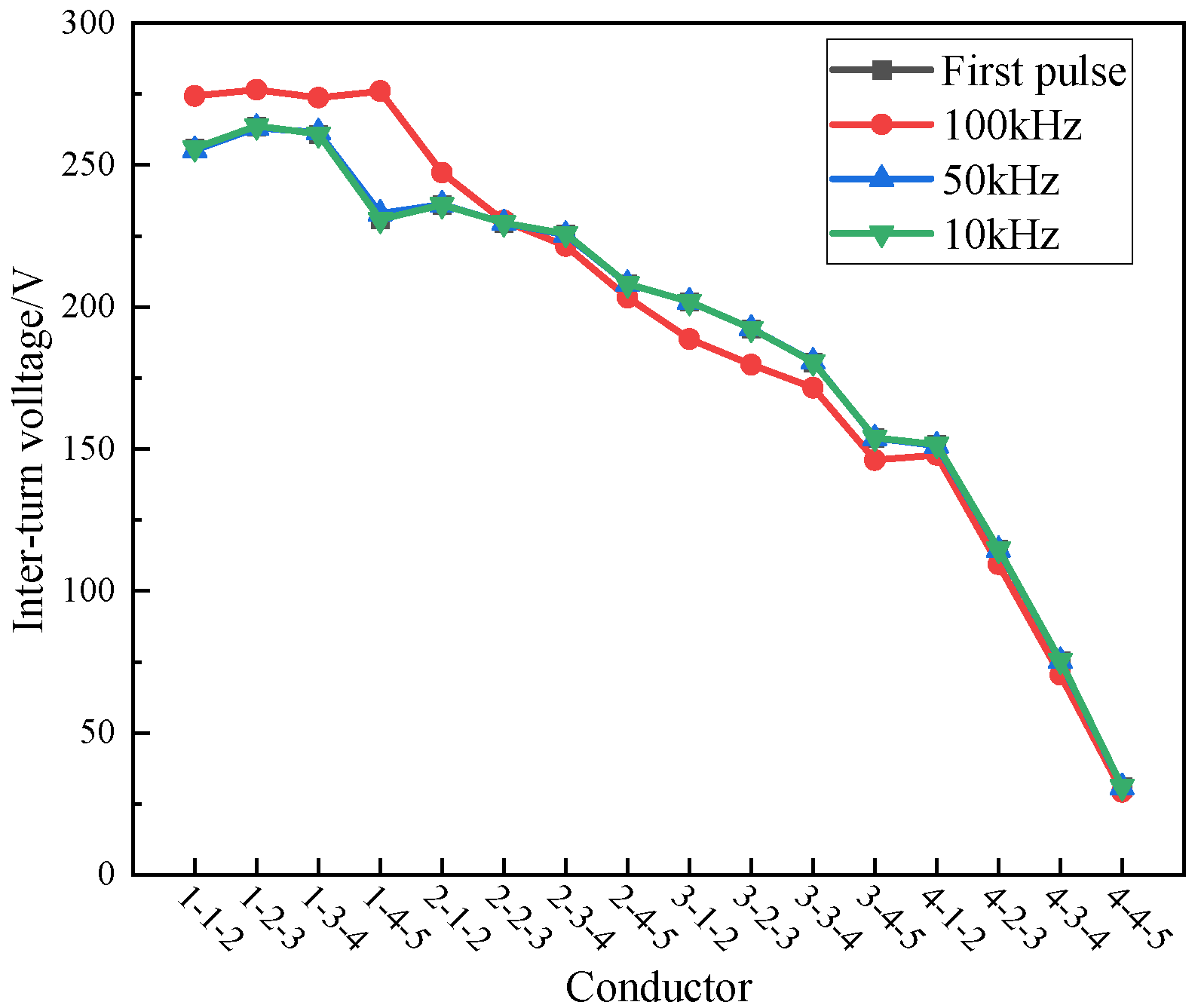
3.2. The Influence of PWM Frequency on the Inter-Turn Voltage Distribution

The inter-turn voltage waveforms at three frequencies of 100 kHz, 50 kHz, and 10 kHz are the same as the first pulse rising edge overvoltage waveform, and the difference is still the overvoltage waveform generated by the second pulse. With the decrease in frequency, the frequency is reduced to 50 kHz and below. The inter-turn voltage waveform generated by the two pulse waves in coil 1 tends to be consistent, as shown in Figure 10.
As shown in Figure 10, the first pulse (black curve) marked in the figure represents the overvoltage generated by the first pulse wave at different frequencies. It can be seen from the figure that the inter-turn voltage distribution of adjacent conductors in different coils of the stator winding of the permanent magnet wind turbine is the same. The inter-turn overvoltage generated by the first pulse wave at different frequencies is the same. The maximum voltage drop is 263 V, which is about 8.8 times the average voltage of the winding. It is located between the 2–3 conductors in the first coil 1 of the stator winding. The change law of the inter-turn voltage between 10 kHz and 50 kHz is consistent with the overvoltage generated by the first pulse wave, and the maximum inter-turn voltage is also about 263 V. When the frequency is 100 kHz, the maximum inter-turn overvoltage is located between the 2–3 conductors in the first coil 1, and the size is 276 V, which is about 9.2 times the average voltage of the winding.

4. The Influence of Cable Length on the Overvoltage Distribution of Permanent Magnet Motor

Because the impedance of the connecting cable at the end of the motor does not match, the refraction and reflection process of the voltage wave will be generated. In this process, when the cable length is long enough when the first reflection wave reaches the converter end, the output voltage of the converter rises completely, and the voltage wave reflected by the converter to the motor end does not rise. At this time, the motor end voltage is the largest. When the cable length is not long enough, the inverter outputs a negative reflected wave when the first reflected wave reaches the inverter end, so that the motor end voltage is less than the maximum value. The critical cable length is solved by Equation (2):
l = v t r 2
In Formula (2), l denotes the critical cable length, v denotes the wave velocity, and tr denotes the rise time of the pulse.
Under ideal conditions, total reflection occurs at the cable and the motor, and negative total reflection occurs at the inverter. The overvoltage at the end of the permanent magnet motor is as follows:
u ( t ) = U 1 + 1 ( 1 ) 2 n
In Equation (3), U represents the input voltage, n is the number of reflections, and u(t) represents the voltage amplitude at the end of the motor.

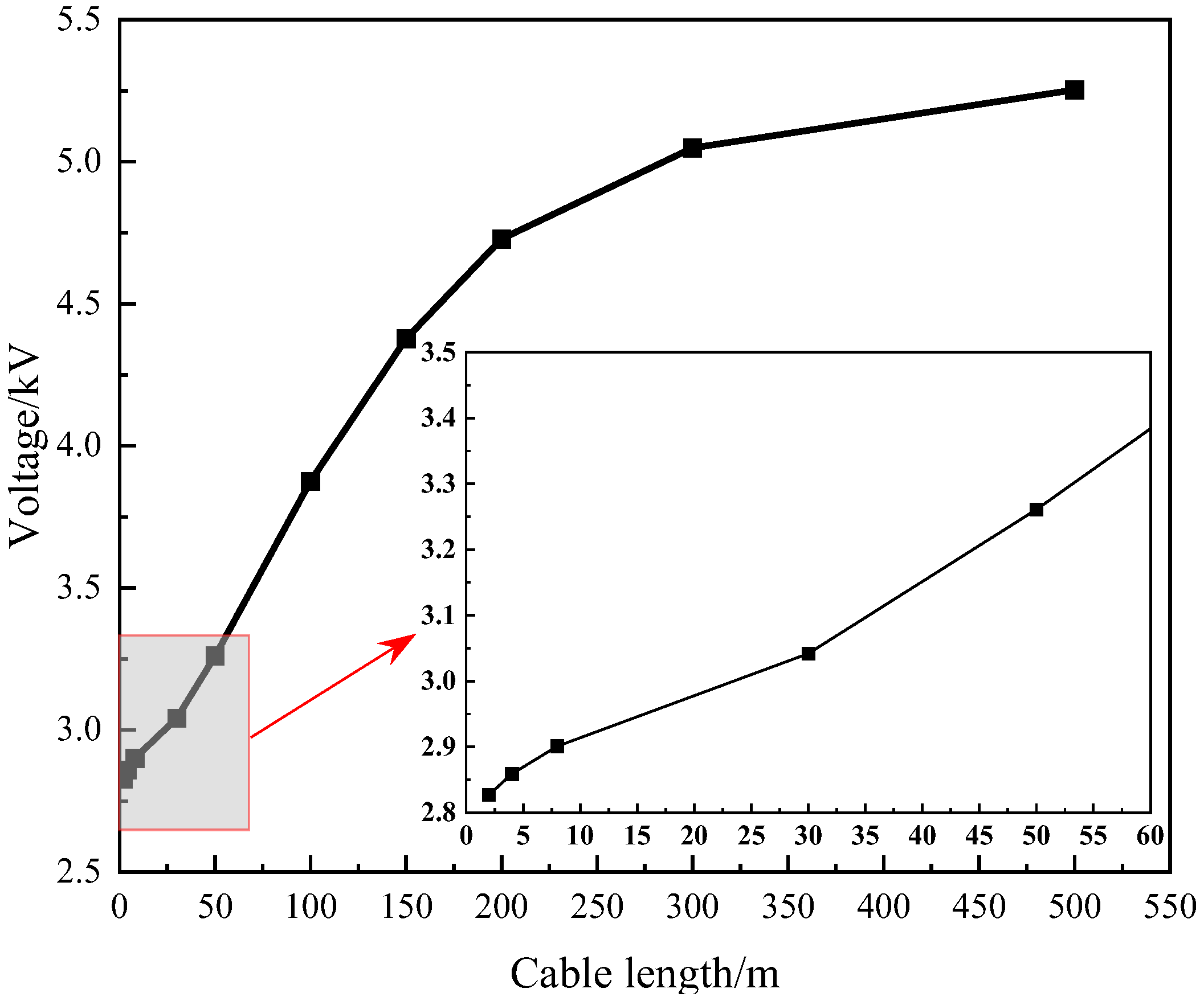
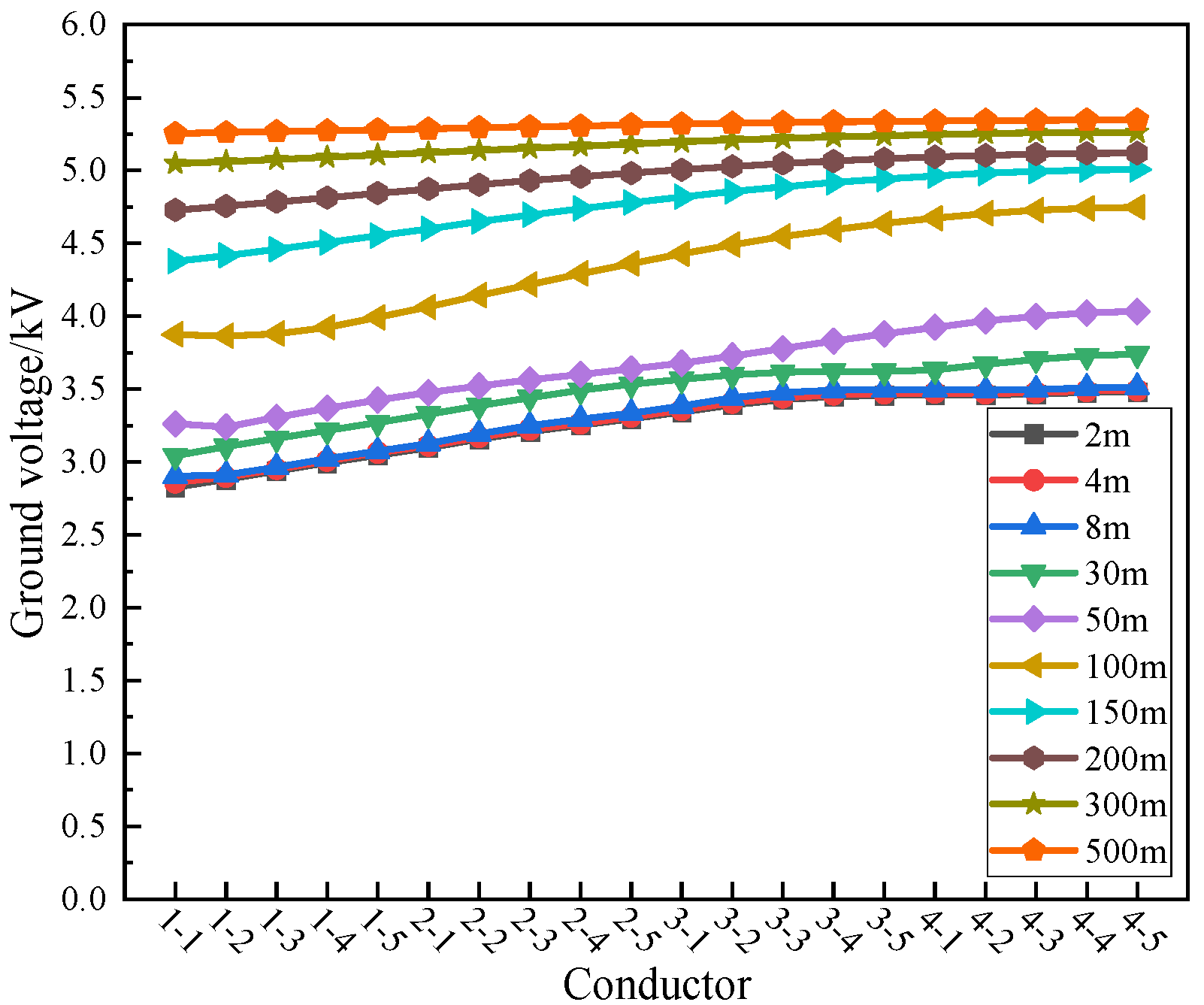
4.1. The Influence of Cable Length on the End-to-Ground Voltage Distribution

When studying the influence of the length of the connecting cable at the end of the permanent magnet wind turbine on the overvoltage distribution, the influence of other conditions is ignored. For the input PWM pulse of the permanent magnet wind turbine, the input is set to a single pulse, the rising edge is set to 2 μs, and the pulse amplitude is set to 2800 V. The influence of different cable lengths on the voltage distribution characteristics of the motor end, winding to ground and inter-turn, is studied. According to the theory, the critical cable length is 300 m, and the maximum voltage should be 5.6 kV. Figure 11 shows the maximum ground voltage of the first-turn conductor under different cable lengths.
It can be seen from Figure 11 that as the cable length increases, the maximum ground voltage at the end of the motor increases when the cable length is less than 300 m, and the maximum voltage changes rapidly with the length, about 10 V/m. After the cable length is greater than 300 m, the maximum voltage increases slowly, only 1.7 V/m, so the critical cable length is determined to be near 300 m. The simulation results are close to the theoretical results.
Figure 12 below is the distribution evolution diagram of the maximum value of the ground voltage of each turn conductor in the four coils of the generator stator winding under different cable lengths.
It can be seen from Figure 12 that when the cable length is below 300 m, the first turn of the ground voltage of each conductor of the winding is slightly lower than the last turn, with a difference of about 0.25 kV. When the cable length is 300 m and above, the maximum ground voltage of each conductor of the winding is the same as the first turn and the last turn. The maximum ground voltage appears at the end turn of the coil, about 5.4 kV, which is 3.6% different from the theoretical 5.6 kV.

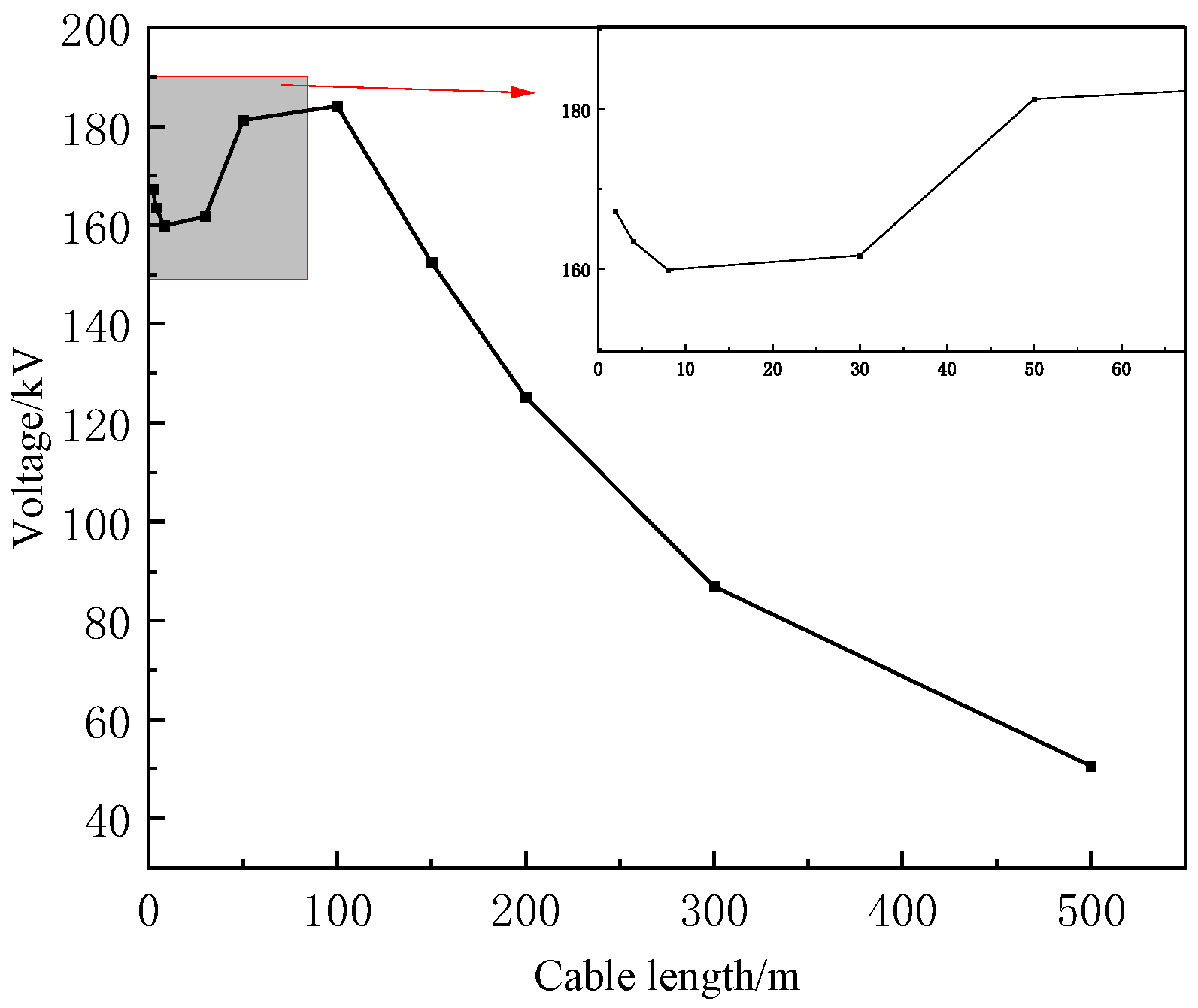
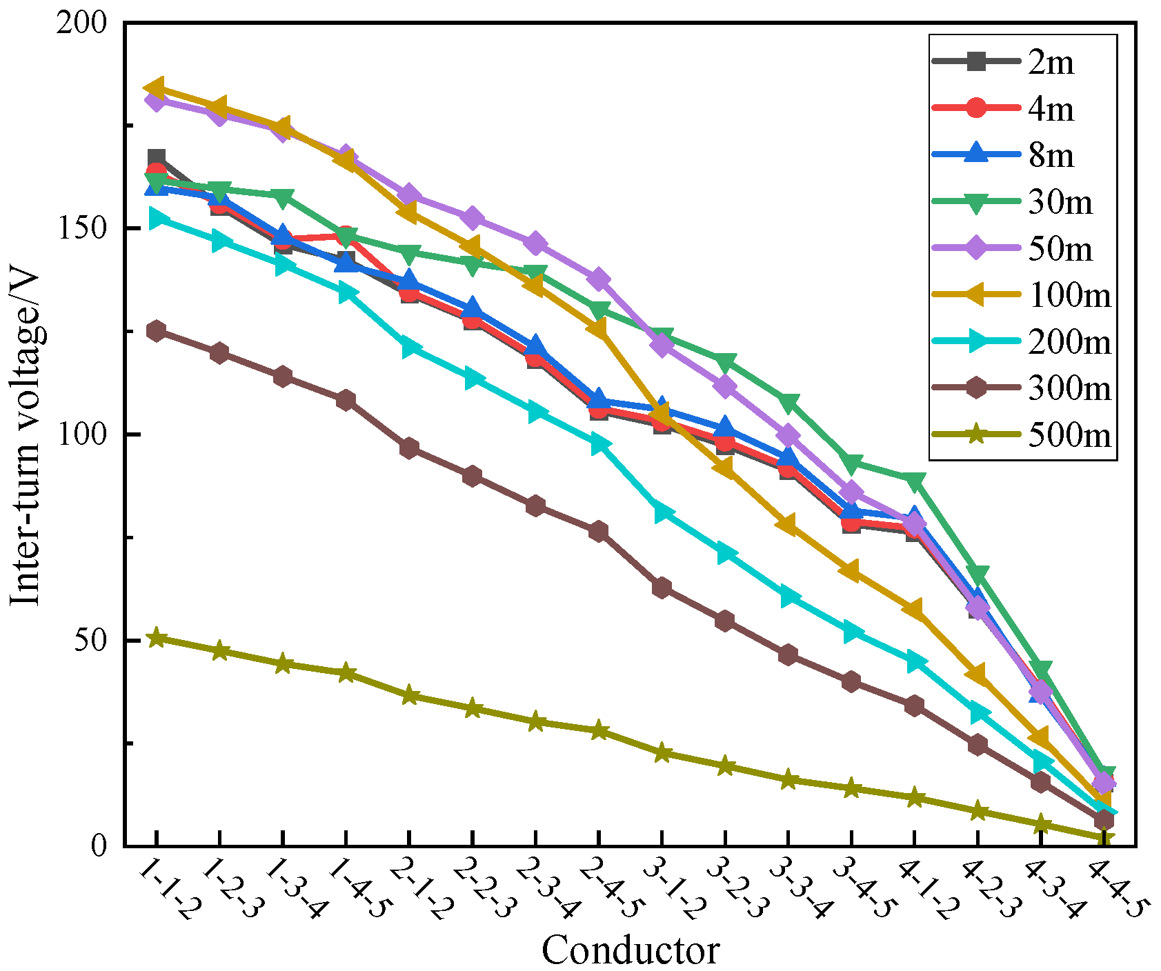
4.2. The Influence of Cable Length on Inter-Turn Overvoltage Distribution

Figure 13 below shows the maximum inter-turn voltage variation in the winding with the change in cable length.
It can be seen from Figure 13 that the inter-turn voltage of the head coil decreases with the increase in the cable length before the cable length is 30 m. In the range of 30 m to 150 m in length, the inter-turn voltage of the head coil increases with the increase in the cable length. In the length of 150 m to 500 m, the inter-turn voltage of the head coil decreases again with the increase in the cable length.
Figure 14 shows the inter-turn voltage distribution characteristics of adjacent conductors in the stator winding of the motor under different cable lengths.
When the cable length is in the range of 50–100 m, the maximum inter-turn voltage reaches the maximum value, which is located at the head coil, and the amplitude is about 185 V. The inter-turn voltage of the end coil is small, and the lowest is close to 0 V.

5. Conclusions

In this paper, the equivalent circuit model of the stator winding and the connecting cable of the permanent magnet machine are built, respectively. By changing the input PWM pulse frequency and the length of the end connecting cable, the distribution law of the ground voltage and the inter-turn voltage distribution at the end of the stator winding coil is studied. The conclusions are as follows:
(1)
The pulse frequency is small, for example, between 10 kHz and 50 kHz, the second pulse wave’s rising edge before the arrival of the first pulse wave’s falling edge has been completely attenuated, and the change in frequency does not affect the distribution of ground voltage and inter-turn voltage; the maximum ground voltage is located at the end of the stator winding coil, and the maximum inter-turn voltage is concentrated between the 2–3 conductors in the first end coil 1; when the frequency is large, such as 100 kHz, the second pulse wave rising edge overvoltage will be affected by the first pulse wave falling edge overvoltage and thus higher, the highest position of 3.7 kV, 1.32 times the input voltage. The results of this test show that there is a critical frequency, which in the motor used in this paper lies between 50 kHz and 100 kHz. The degree of influence of frequency on voltage is small and the maximum magnitude is only 1.32 times.
(2)
There is a critical value corresponding to the length of the cable. Before the critical value, the length of the cable increases, and the voltage at the end of the stator winding will increase. After the critical value, it tends to be stable, and the ground voltage can reach up to 5.4 kV. As the cable length increases, the voltage distribution of the entire winding begins to become uniform, and the maximum ground voltage is concentrated in the middle and rear of the coil. The maximum inter-turn voltage decreases first, then increases, and finally decreases with the increase in cable length, which is concentrated between the 1–2 and 2–3 conductors of the head coil, up to 185 V. The cable length has a large effect on the overvoltage, and the maximum voltage can be close to twice the input voltage at constant frequency.

Author Contributions

Conceptualization, S.Z.; Methodology, D.C.; Software, S.L.; Validation, H.L.; Formal analysis, F.T.; Writing—original draft, Y.L. All authors have read and agreed to the published version of the manuscript.

Funding

This research received no external funding.

Institutional Review Board Statement

Not applicable.

Informed Consent Statement

Not applicable.

Data Availability Statement

The original contributions presented in the study are included in the article, further inquiries can be directed to the corresponding author.

Conflicts of Interest

Authors Shifu Zhang, Shulin Li and Dahu Cheng were employed by the company Beijing Goldwind Science and Technology Innovation Wind Power Equipment Co., Ltd. The remaining authors declare that the research was conducted in the absence of any commercial or financial relationships that could be construed as a potential conflict of interest.

References

  1. Global Wind Report. 2024. Available online: https://gwec.net/global-wind-report-2024/ (accessed on 28 June 2024).
  2. Wu, Y.-K.; Su, Y.-S.; Su, P.-E.; Wu, T.-Y. Economics- and reliability-based design for an offshore wind farm. In Proceedings of the 2017 IEEE/IAS 53rd Industrial and Commercial Power Systems Technical Conference (I&CPS), Niagara Falls, ON, Canada, 6–11 May 2017; pp. 1–9. [Google Scholar]
  3. Qiao, W.; Lu, D. A Survey on Wind Turbine Condition Monitoring and Fault Diagnosis—Part I: Components and Subsystems. In Proceedings of the IEEE Transactions on Industrial Electronics, Auckland, New Zealand, 15–17 June 2015; Volume 62, pp. 6536–6545. [Google Scholar]
  4. Huang, Y.; Luo, Y.; Xiao, F.; Liu, B. Failure Mechanism of Die-Attach Solder Joints in IGBT Modules Under Pulse High-Current Power Cycling. IEEE J. Emerg. Sel. Top. Power Electron. 2018, 7, 99–107. [Google Scholar] [CrossRef]
  5. von Jouanne, A.; Enjeti, P. Design considerations for an inverter output filter to mitigate the effects of long motor leads in ASD applications. In Proceedings of the Applied Power Electronics Conference, APEC’96, San Jose, CA, USA, 3–7 March 1996; Volume 2, pp. 579–585. [Google Scholar]
  6. Arnedo, L.; Venkatesan, K. High-frequency modeling of induction motor drives for EMI and overvoltage mitigation studies. In Proceedings of the IEEE International Electric Machines and Drives Conference, IEMDC’03, Madison, WI, USA, 1–4 June 2003; pp. 468–474. [Google Scholar]
  7. Rendusara, D.A.; Enjeti, P.N. An improved inverter output filter configuration reduces common and differential modes dv/dt at the motor terminals in PWM drive systems. IEEE Trans. Power Electron. 1998, 13, 1135–1143. [Google Scholar] [CrossRef]
  8. Chen, S.; Lipo, T.A.; Fitzgerald, D. Source of induction motor bearing currents caused by PWM inverters. IEEE Trans. Energy Convers. 1996, 11, 25–32. [Google Scholar] [CrossRef]
  9. von Jouanne, A.; Enjeti, P.; Gray, W. Application issues for PWM adjustable speed AC motor drives. IEEE Ind. Appl. Mag. 1996, 2, 10–18. [Google Scholar] [CrossRef]
  10. Ma, H.; Xu, D.; Chen, X.; Jiang, Y. Study of voltage reflection phenomenon when PWM inverter drives asynchronous motor with long wire cable. Chin. J. Electr. Eng. 2001, 21, 110–114. [Google Scholar]
  11. Ortega, R.; de Rinaldis, A.; Spong, M.W.; Lee, S.; Nam, K. On compensation of wave reflections in transmission lines and applications to the overvoltage problem AC motor drives. IEEE Trans. Autom. Control 2004, 49, 1757–1763. [Google Scholar] [CrossRef]
  12. Li, L.; Liu, C. Research on the effect of variable frequency power supply on the insulation performance of cables. Insul. Mater. 2009, 42, 36–39+45. [Google Scholar]
  13. Skibinski, G.; Kerkman, R.; Leggate, D.; Pankau, J.; Schlegel, D. Reflected wave modeling techniques for PWM AC motor drives. In Proceedings of the APEC’98 Thirteenth Annual Applied Power Electronics Conference and Exposition, Anaheim, CA, USA, 15–19 February 1998; Volume 2, pp. 1021–1029. [Google Scholar]
  14. De Paula, H.; de Andrade, D.A.; Chaves, M.L.R.; Domingos, J.L.; de Freitas, M.A.A. Methodology for Cable Modeling and Simulation for High-Frequency Phenomena Studies in PWM Motor Drives. IEEE Trans. Power Electron. 2008, 23, 744–752. [Google Scholar] [CrossRef]
  15. Yu, G. A recursive algorithm for calculating motor end voltages of long cables. Electr. Drives 2015, 45, 76–80. [Google Scholar]
  16. Zhang, C.; Zhang, J.; Huang, X.; Chen, G.; Ni, Z.; Hu, Y. Overvoltage modeling of motor end of a PWM drive system with long cable connection. Micro Motor 2021, 54, 27–30+56. [Google Scholar]
  17. Suresh, G.; Toliyat, H.A.; Rendussara, D.A.; Enjeti, P.N. Predicting the transient effects of PWM voltage waveform on the stator windings of random wound induction motors. In Proceedings of APEC 97—Applied Power Electronics Conference, Atlanta, GA, USA, 27 February 1997; Volume 1, pp. 135–141. [Google Scholar]
  18. Tang, Y. Analysis of steep-fronted voltage distribution and turn insulation failure in inverter-fed form-wound AC motor. IEEE Trans. Ind. Appl. 1998, 34, 1088–1096. [Google Scholar] [CrossRef]
  19. Wu, W.; Jiang, Y.; Liu, Y.; Huang, M.; He, Y.; Chung, S.-H. A new passive filter design method for overvoltage suppression and bearing currents mitigation in a long cable based PWM inverter-fed motor drive system. In Proceedings of the 2016 IEEE 8th International Power Electronics and Motion Control Conference (IPEMC-ECCE Asia), Hefei, China, 22–26 May 2016; pp. 3103–3110. [Google Scholar]
  20. Liu, Y.; Du, J.; Zhao, X.; Song, Y.; Wang, Y. High-Frequency Harmonic Suppression Strategy and Modified Notch Filter-Based Active Damping for Low-Inductance HPMSM. Appl. Sci. 2023, 13, 11309. [Google Scholar] [CrossRef]
  21. Shojaee, M.; Azizi, S.M. Decentralized Robust Control of a Network of Inverter-Based Distributed Generation Systems. Appl. Sci. 2023, 13, 9517. [Google Scholar] [CrossRef]
  22. Mansouri, A.; Ammar, A.; El Magri, A.; Elaadouli, N.; Younes, E.K.; Lajouad, R.; Giri, F. An adaptive control strategy for integration of wind farm using a VSC-HVDC transmission system. Results Eng. 2024, 23, 102359. [Google Scholar] [CrossRef]
  23. Borodin, M.Y.; Metelkov, V.P.; Fedorova, S.V.; Permyakov, G.A. To the development of a model for the study of overvoltage in an asynchronous electric drive with a PWM frequency converter. In Proceedings of the 2021 XVIII International Scientific Technical Conference Alternating Current Electric Drives (ACED), Ekaterinburg, Russia, 24–27 May 2021; pp. 1–4. [Google Scholar]
  24. Wheeler, J.C.G. Effects of converter pulses on the electrical insulation in low and medium voltage motors. IEEE Electr. Insul. Mag. 2005, 21, 22–29. [Google Scholar]
  25. Fabiani, D.; Montanari, G.C.; Cavallini, A.; Mazzanti, G. Relation between space charge accumulation and partial discharge activity in enameled wires under PWM-like voltage waveforms. IEEE Trans. Dielectr. Electr. Insul. 2004, 11, 393–405. [Google Scholar] [CrossRef]
Figure 1. The specific structure and layout of the cable.
Applsci 14 09220 g001
Figure 2. Single-phase cable distributed parameter equivalent circuit.
Applsci 14 09220 g002
Figure 3. Equivalent circuit of high-frequency lossless transmission line.
Applsci 14 09220 g003
Figure 4. The distributed capacitance diagram of three-phase cable.
Applsci 14 09220 g004
Figure 5. Single coil equivalent circuit model.
Applsci 14 09220 g005
Figure 6. Simulation waveform of ground voltage at 100 kHz.
Applsci 14 09220 g006
Figure 7. Simulation waveform of ground voltage at 50 kHz.
Applsci 14 09220 g007
Figure 8. Simulation waveform of ground voltage at 10 kHz.
Applsci 14 09220 g008
Figure 9. The maximum ground voltage distribution characteristics of windings at different frequencies.
Applsci 14 09220 g009
Figure 10. Distribution characteristics of winding inter-turn voltage at different frequencies.
Applsci 14 09220 g010
Figure 11. The maximum ground voltage of the first-turn conductor under different cable lengths.
Applsci 14 09220 g011
Figure 12. Characteristics of the maximum voltage distribution to ground of the windings for different cable lengths.
Applsci 14 09220 g012
Figure 13. The maximum inter-turn voltage of winding under different cable lengths.
Applsci 14 09220 g013
Figure 14. Distribution characteristics of winding inter-turn voltage under different cable lengths.
Applsci 14 09220 g014
Table 1. Distributed capacitance of permanent magnet synchronous wind generator.
Capacitor/pFC1C2C3C4C5
C1496.31046.2
C21046.2587.71013.6
C3 1013.6620.4978.8
C4 978.8587.8938.4
C5 938.4492.2
Note: The diagonal lines in the table represent the ground capacitance of each turn conductor, and the non-diagonal elements represent the inter-turn capacitance of different conductors.
Table 2. Distributed inductance of permanent magnet wind turbine.
Inductor/μH1st Turn2nd Turn3rd Turn4th Turn5th Turn
1st turn16.015.414.914.313.8
2nd turn15.415.915.414.814.3
3rd turn14.915.415.915.414.8
4th turn14.314.815.415.815.4
5th turn13.814.314.815.415.8
Note: The diagonal in Table 2 is the equivalent self-inductance of each conductor, and the rest is the equivalent mutual inductance between different conductors.
Disclaimer/Publisher’s Note: The statements, opinions and data contained in all publications are solely those of the individual author(s) and contributor(s) and not of MDPI and/or the editor(s). MDPI and/or the editor(s) disclaim responsibility for any injury to people or property resulting from any ideas, methods, instructions or products referred to in the content.

