Article

New Concept of Dual-Sinusoid Distributed Fiber-Optic Sensors Antiphase-Placed for the SHM of Smart Composite Structures for Offshore

1
Department of Architecture, Built Environment and Construction Engineering, Politecnico di Milano, 20133 Milan, Italy
2
Department of Components and Systems, Université Gustave Eiffel, 77447 Marne-la-Vallée, France
3
International Associated Laboratory (UGE-Polimi), SenSIN-CT, 77447 Marne-la-Vallée, France
*
Author to whom correspondence should be addressed.
Appl. Sci. 2024, 14(2), 932; https://doi.org/10.3390/app14020932
Submission received: 29 November 2023 / Revised: 16 January 2024 / Accepted: 18 January 2024 / Published: 22 January 2024
(This article belongs to the Special Issue Advances in Reinforced Concrete Structural Health Monitoring)

Abstract

:
This work is a follow-up to previous research by our team and is devoted to studying a dual-sinusoidal placement of distributed fiber-optic sensors (FOSs) that are embedded inside an adhesive joint between two composite laminates. The constructed smart continuous fiber-reinforced polymer composite structure is well suited to the structural health monitoring (SHM) system for offshore wind turbine blades. Three main drawbacks of SHM through embedded distributed FOSs, however, have been identified in this article, so their impact must be analyzed. Despite existing research, the influence of the dual-sinusoidal placement under various loading conditions on structural mechanical behavior and sensing functionality has not been considered yet since its introduction. Thus, this study aims to identify the resulting strain patterns and sensing capabilities from an optimized dual-sinusoidal placement of FOSs in various loading cases through finite element modeling. Ultimately, this work illustrates the strain-measuring advantages of dual-sinusoidal FOSs, explains the correspondence between the strains measured by FOSs and that of host structures, and discusses the balance among mechanical influences, sensing functions, and monitoring coverage. It is worth noting that the current work is a still introductory concept that aims at refining key parameters that have been emphasized in previous research, before starting an applied study that will consider both numerical and validation steps on real large smart composite structures.

1. Introduction

In recent years, many research works have been devoted to the placement of sensors inside composites for structural health monitoring (SHM) of the offshore wind sector (e.g., offshore wind turbine blades and high-voltage power cables) [1,2,3,4,5,6] because it is fast-growing and more promising than its onshore counterpart in helping wind energy stay on course for the 1.5 °C and net zero pathway set out by International Renewable Energy Agency [5,7,8,9]. Current offshore wind turbine blades manufactured by companies General Electric, Vestas, MingYang, and Siemens exceed 100 m to realize exceptional energy-generation performances and reduce the leveraged cost of energy [10,11,12]. This increase in size entails the switch from glass to carbon-fiber-reinforced polymers (CFRP) for lighter, stronger, and stiffer blades [11,13], along with appropriate SHM strategies that can ensure reliable service over 20 years, at least.
Areas of weakness in a CFRP blade have been identified as the root sections and trailing edge bonds, and corresponding reinforcement strategies have been suggested to ensure reliability [1,2,3,4,5,13,14]. Meanwhile, a continuous, automatic, and in situ SHM system is highly desirable. Because, compared to conventional inspection programs, it is promising in remotely alerting operators to any dangerous event (e.g., overloads or damage initiation) in a timely manner, thereby approaching maintenance-free operation and avoiding sudden catastrophic failures of deteriorated CFRP structures due to uncertainties [15,16,17].
The SHM concept can be more easily understood by comparison with the way a human body works [16]. First of all, an “unhealthy” condition must be detected by the nervous system, which is similar to the sensing subsystem in SHM where sensors react to environments and provide measurements of parameters (e.g., mechanical strain) [1,2]. To gather maximum information concerning health conditions of structures under various load conditions, ideally, nerves/sensors provide full coverage of not only structural surfaces but also structural volume. This requires sensors be bonded/embedded into structures at representative locations, in addition to being installed on surfaces, which can also enhance protection of sensors from external harsh environments [1,2,3,4,5,15,18,19,20,21].
Fiber-optic sensors (FOSs), as shown in Figure 1, have proven strain-measuring capabilities and suitability for embedment into CFRP composites [15,22,23,24,25,26]. Their immunity to electromagnetic interference and noise and their intrinsic link to optical transit cables allow them to keep the signal quality with low loss, such that their sensing functions can be extended for long-distance applications [1,23,24]. Furthermore, rather than monitoring a measurand only at a limited number of pre-determined points (discrete locations), distributed FOSs can determine the continuous spatial distribution of one or more measurands along long fibers of many kilometers [23]. This is a unique property of distributed FOSs, which is unparalleled by any other techniques, especially when the area to be monitored is extended and/or when the required density of sensing points is high [27].
Nevertheless, the main drawbacks of SHM through embedded distributed FOSs are (1) one single-mode FOS is only capable of sensing accurately a local area around 10 mm away from it, (2) the FOS’s interrogator system is expensive (e.g., several hundred thousand euros), and (3) FOSs are “foreign” materials whose diameters are much larger than those of carbon fibers, thereby inevitably resulting in perturbed strain states around them. Therefore, it is preferable to achieve the largest monitoring coverage with a minimum number of FOSs used. In light of this, linear placement of FOSs is not an optimal solution, as pointed out in previous studies [1,2,3]. Thus, in a preliminary FOS embedment study, Drissi-Habti et al. [1] proposed a novel sinusoidal placement of a single FOS, illustrating its potential for monitoring a larger area by providing multi-directional strain measurements. The same authors [3] further proposed an original dual-sinusoidal placement, where two sinusoidal FOSs were placed 180° out of phase to each other, for a finer SHM system. Numerical and analytical results suggested that both embedded sinusoidal FOSs retained the multi-axial strain-measuring capability and provided complementary strain-measuring areas [3]. Besides optimizing the placement pattern for the largest monitoring coverage, care should also be taken in the influence of FOS embedment on structural mechanical behavior, as well as sensing functionality. It is worthwhile to note that current research is the follow-up to (3) and will use the analytical modeling previously developed in (3). Many works focused on the influence of embedded FOSs due to their characteristics (e.g., diameter and coating material) [1,2,3,15,18,19,20,21,28]. Edge effects, amplitudes, and period sizes of the sinusoidal placement pattern were also checked for their effects on the resulting principal strains but only under uniaxial tensile loading [1,2,3]. The influence of the dual-sinusoidal placement on structural mechanical behavior and sensing functionality under various loading conditions has not been considered yet.
Based on previous research works [1,2,3], this article moves one step toward real-life applications by extending the simulation of a uniaxial tensile loading case to bending and torsion. Because even though offshore wind turbine blades are subjected to complex combined loads in service, primary states can be reduced to a combination of axial tension/compression, bending, and torsion. Moreover, this work extends a meso-scale numerical model (distributed FOSs embedded inside an adhesive bond layer between two CFRP laminae of 0° fiber orientation [1,2,3]) to a coupon-level numerical model of bonded CFRP laminates. As a result, this work helps to recognize the resulting strain patterns (strain components, levels, concentrations, and distributions) and sensing capabilities from an optimized dual-sinusoidal placement of FOSs in different loading cases, which can be useful for further quantitative studies and detailed sensor placement designs in large smart composite structures. Ultimately, through this research work, answers to some key questions can be found. For example, is the concept of dual-sinusoidal placement pattern beneficial? Can the pattern provide extra valuable information? Is the pattern suitable for accurate SHM of smart composites under various load conditions?

2. Finite Element Model Features
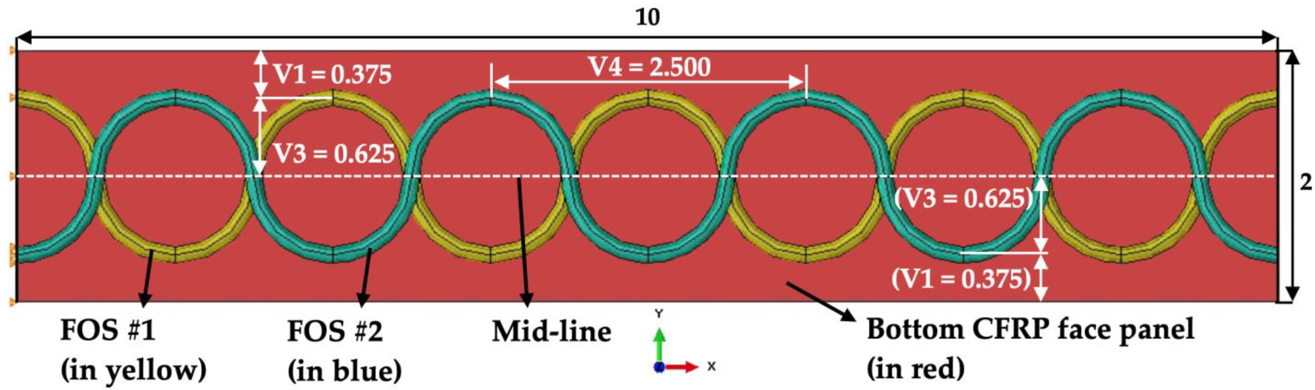
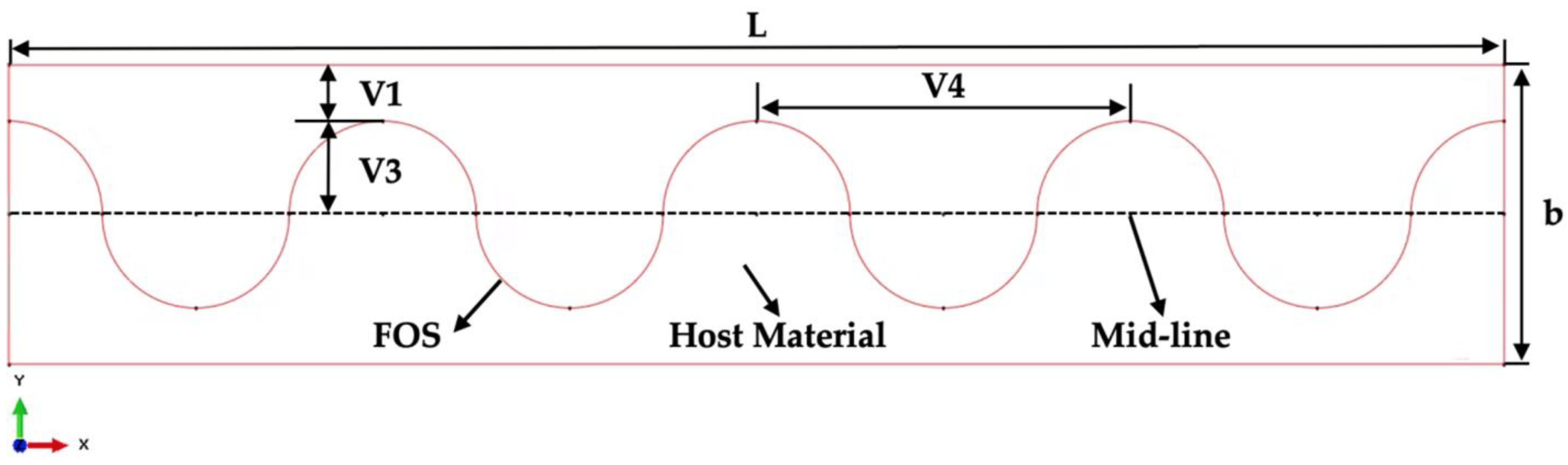
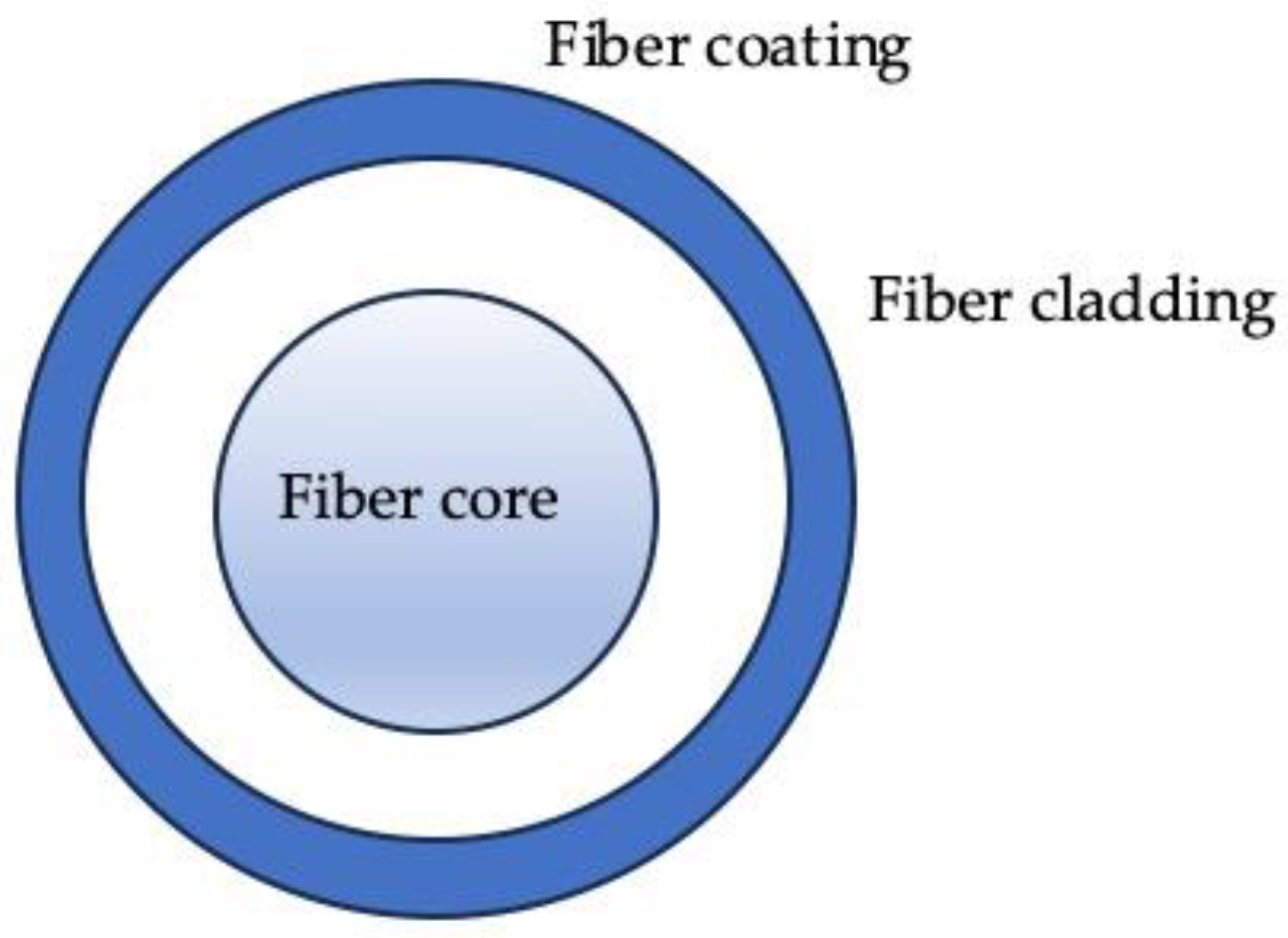
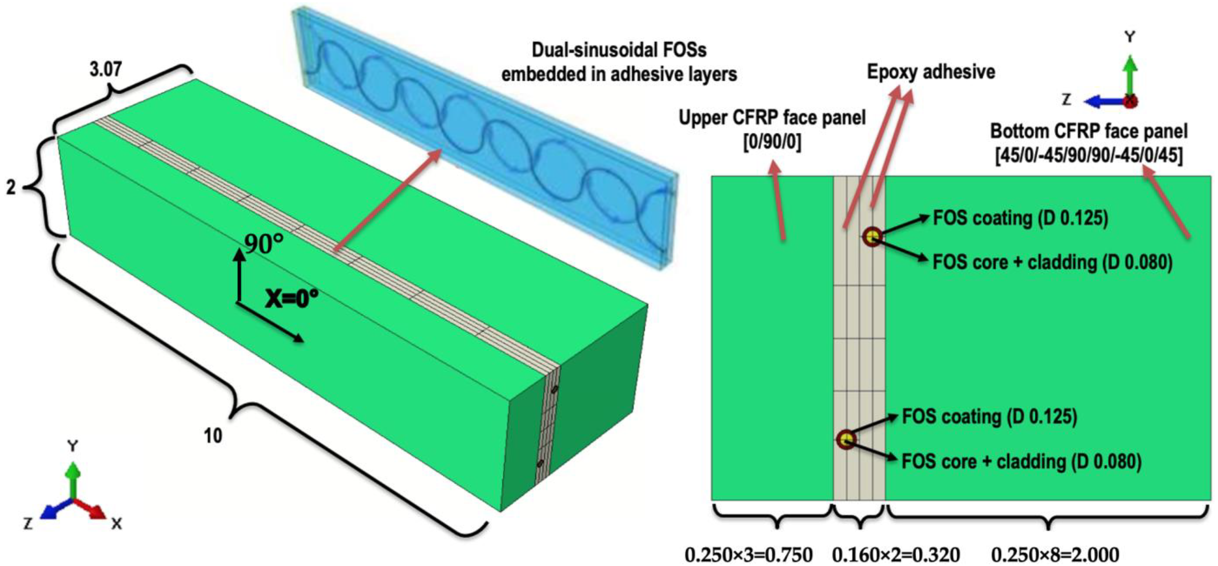
The numerical models are developed using Abaqus® [29]. Consistent with previous studies [1,2,3], distributed FOSs are modeled as being embedded into an adhesive joint between two CFRP laminates.

2.1. Solid Models

As shown in Figure 2, each numerical model is made up of several parts of different materials, which are then assembled for finite element analyses. In brief, two CFRP face panels are bonded together by an epoxy adhesive joint, which hosts dual-sinusoidal FOSs. More specifically, each sinusoidal FOS is aligned toward the X-axis of a global coordinate system with its period size (V4 = 2.500 mm), amplitude (V3 = 0.625 mm), and edge gap (V1 = 0.375 mm) shown in Figure 3; it is modeled with a total diameter of 0.125 mm, including an inner circular part of 0.080 mm diameter (fiber core plus cladding) and an outer annular layer of coating, and is positioned in the middle of an adhesive layer.
Bonding between FOS and adhesive is assumed perfect. Two adhesive layers are then “Tied” into one with a total thickness of 0.320 mm. Two CFRP face panels have lay-up stacking sequences (LSS) of [0°/90°/0°] and [45°/0°/−45°/90°]s, respectively, with each ply of 0.250 mm thickness. More discussions on motivations for this configuration can be found in Section 3.1.

2.2. Material Properties
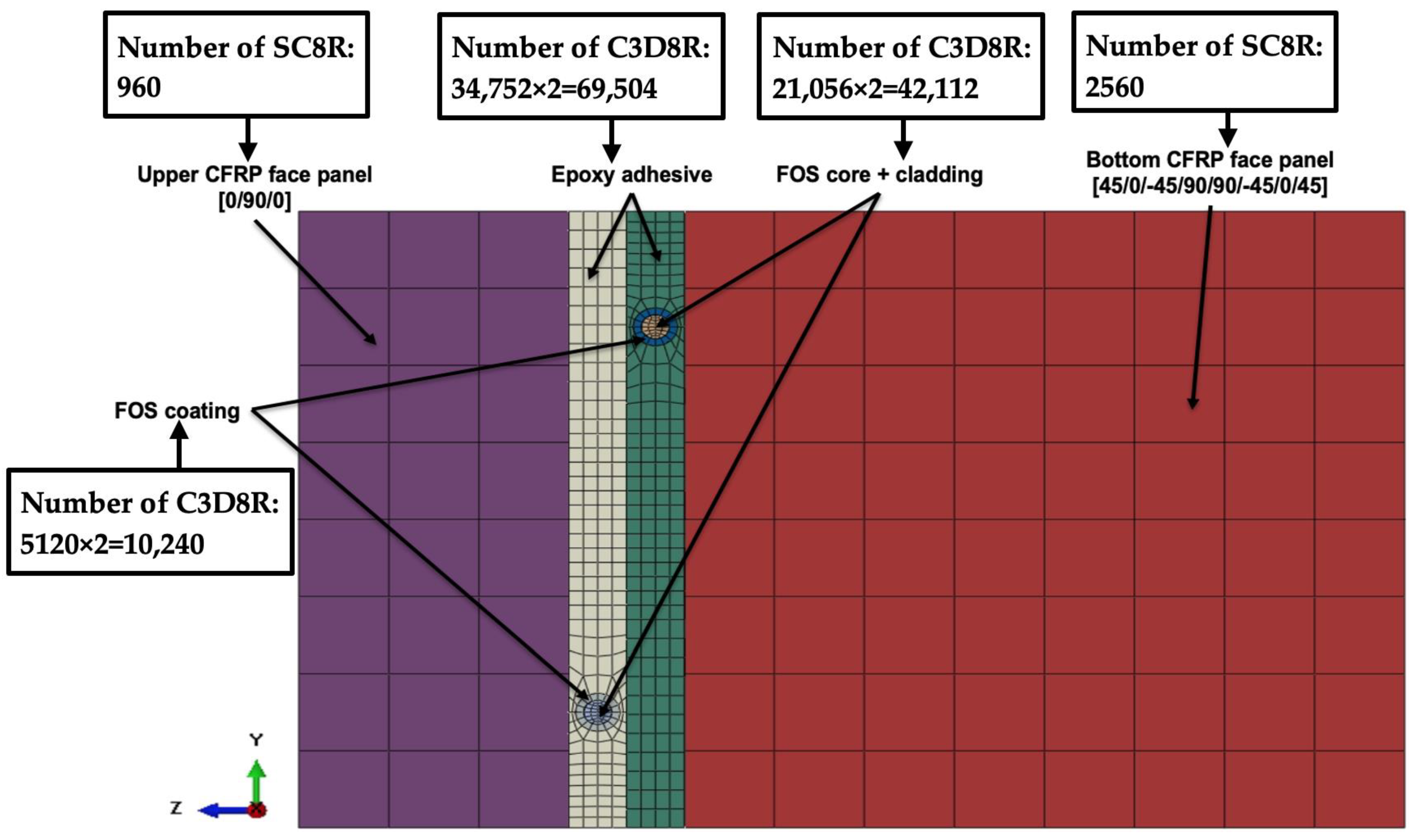
Elastic material properties for different parts are listed in Table 1, where the homogenized lamina properties of unidirectional CFRP are given for top and bottom face panels, and isotropic material properties are considered for all other parts. Epoxy resin material properties have been assigned to adhesive layers, while silica glass material properties have been assigned to the inner circular part of FOS (core plus cladding). Acrylate, as one of the most used FOS coating materials in industries [1], is used for modeling FOS coating.

2.3. Mesh Features

As shown in Figure 4, various mesh densities are selected to allow for accurate prediction of strain patterns while maintaining cost-efficient computation. They are the result of a preliminary mesh sensitivity analysis. The main aim is to identify the resulting strain patterns from the dual-sinusoidal placement under various loading conditions along and around FOSs, and finer meshes are used in these areas accordingly. Different parts are then meshed using different element types: continuum shell elements SC8R for the two CFRP face panels; 3D stress solid elements C3D8R for all other parts. The total number of elements is 125,376, of which 121,856 elements are for C3D8R and 3520 for SC8R elements. A short description of meshing is given hereafter. The assessment of the finite element discretization was performed by assuming that the adhesive layer with the embedded FOSs was the most relevant zone for strain concentration. The mesh discretization had a twofold purpose: to evaluate the variation of the strain field with the mesh density in the adhesive layer (number of elements) and to reduce the computational time. The mesh of the adhesive layer was built with varying density, with higher density in the zones with higher curvatures of the FOSs. The minimum size of the element was set as the thickness of the adhesive (approximately 0.023 mm) between the FOS surface and the interface between the CFRP and the epoxy adhesive (see Figure 3 and Figure 4). This resulted in a total number of 125,376 elements. Additionally, assuming the minimum size of the finite element as half of the above, the maximum strain in the adhesive layer had a 3% difference. Therefore, considering the computational time, we have adopted the first mesh with a minimum element size of about 0.023 mm for the results presented in Section 3.

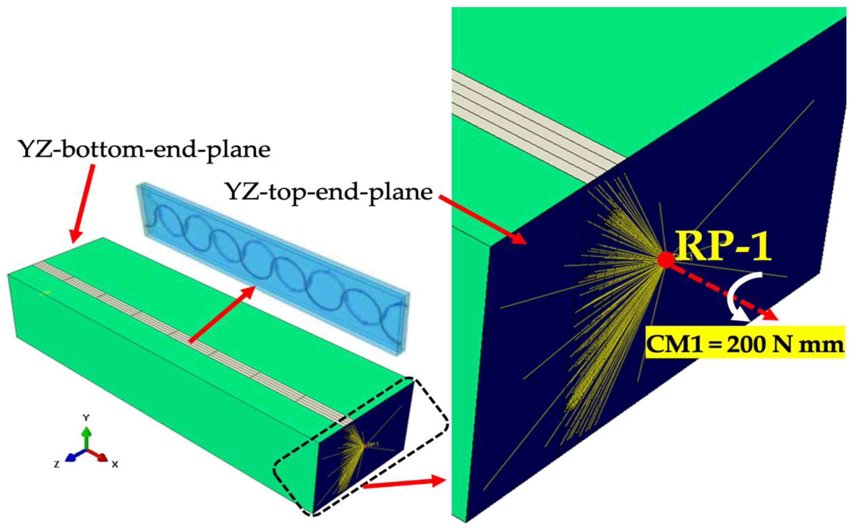
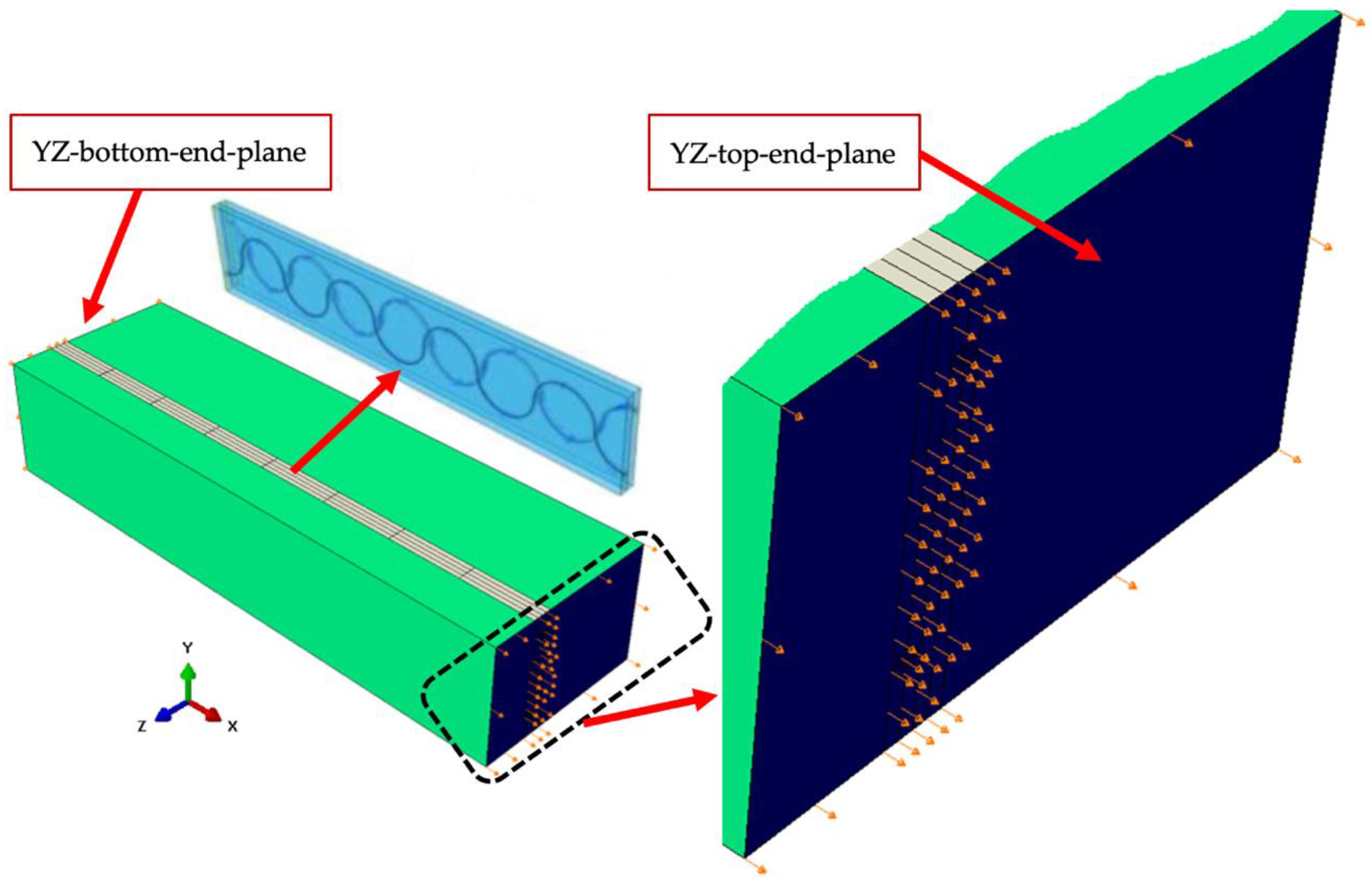
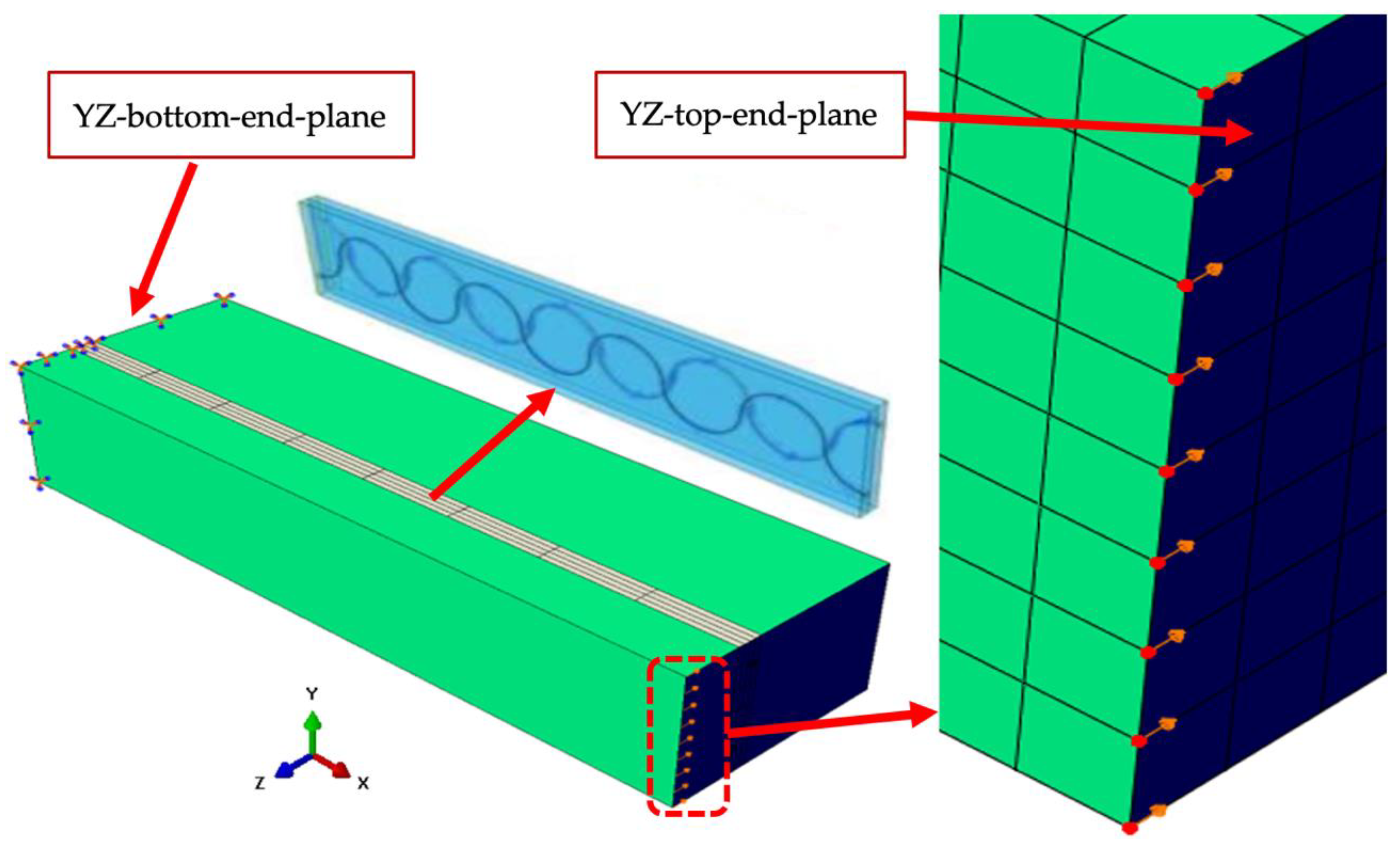
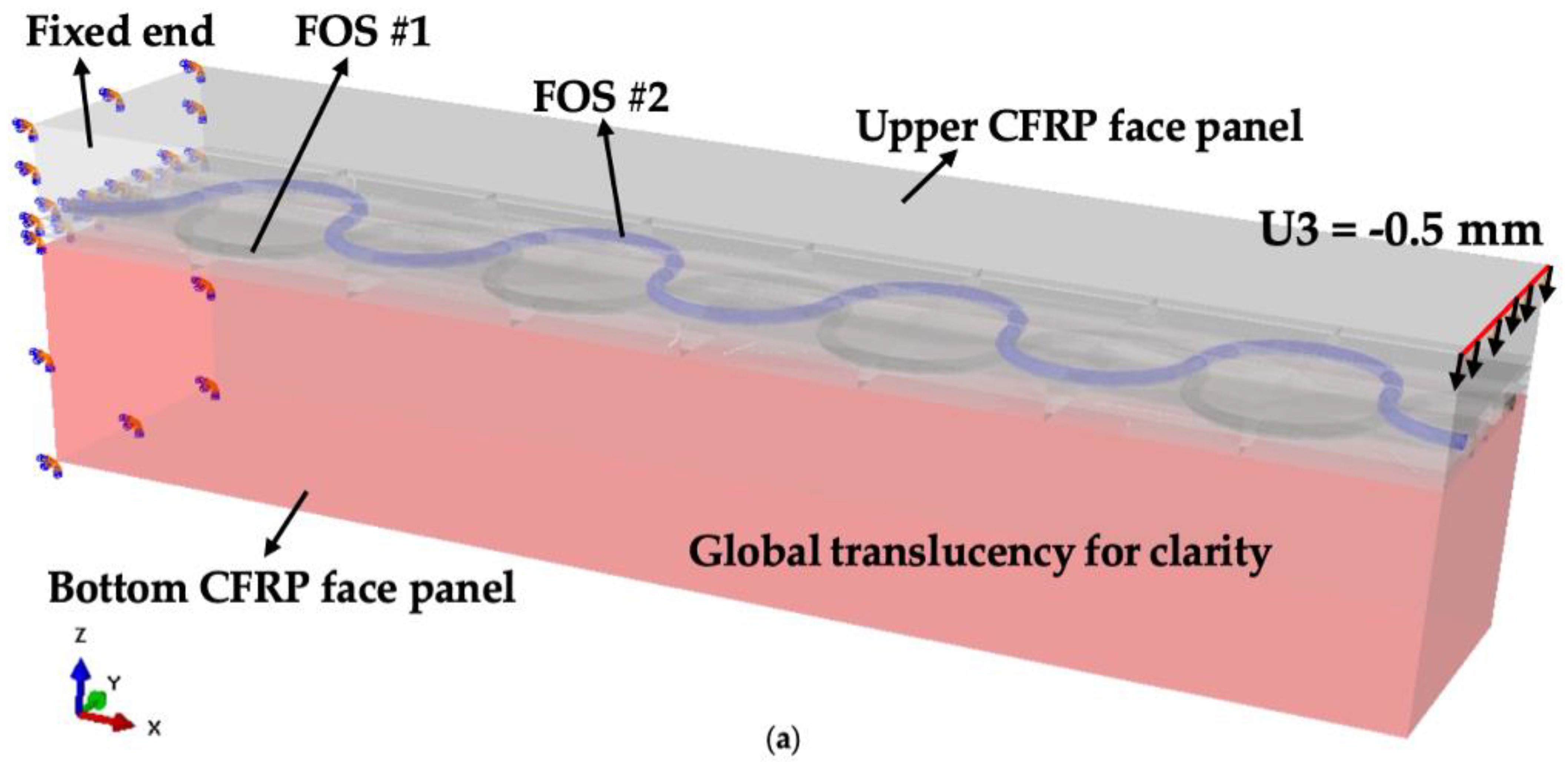
2.4. Boundary Conditions

Three quasi-static loading cases are studied, namely tension, cantilever bending, and torsion. Boundary conditions for each of them are introduced in detail as the following.

2.4.1. Tension

Quasi-static tensile loading is applied by setting an axial displacement along the X-axis on the YZ-top-end-plane (U1 = 0.5 mm), as shown in Figure 5. At the other end (YZ-bottom-end-plane), the displacement in the X-direction is constrained, as well as the rotation around the Y-axis and Z-axis, respectively.

2.4.2. Cantilever Bending
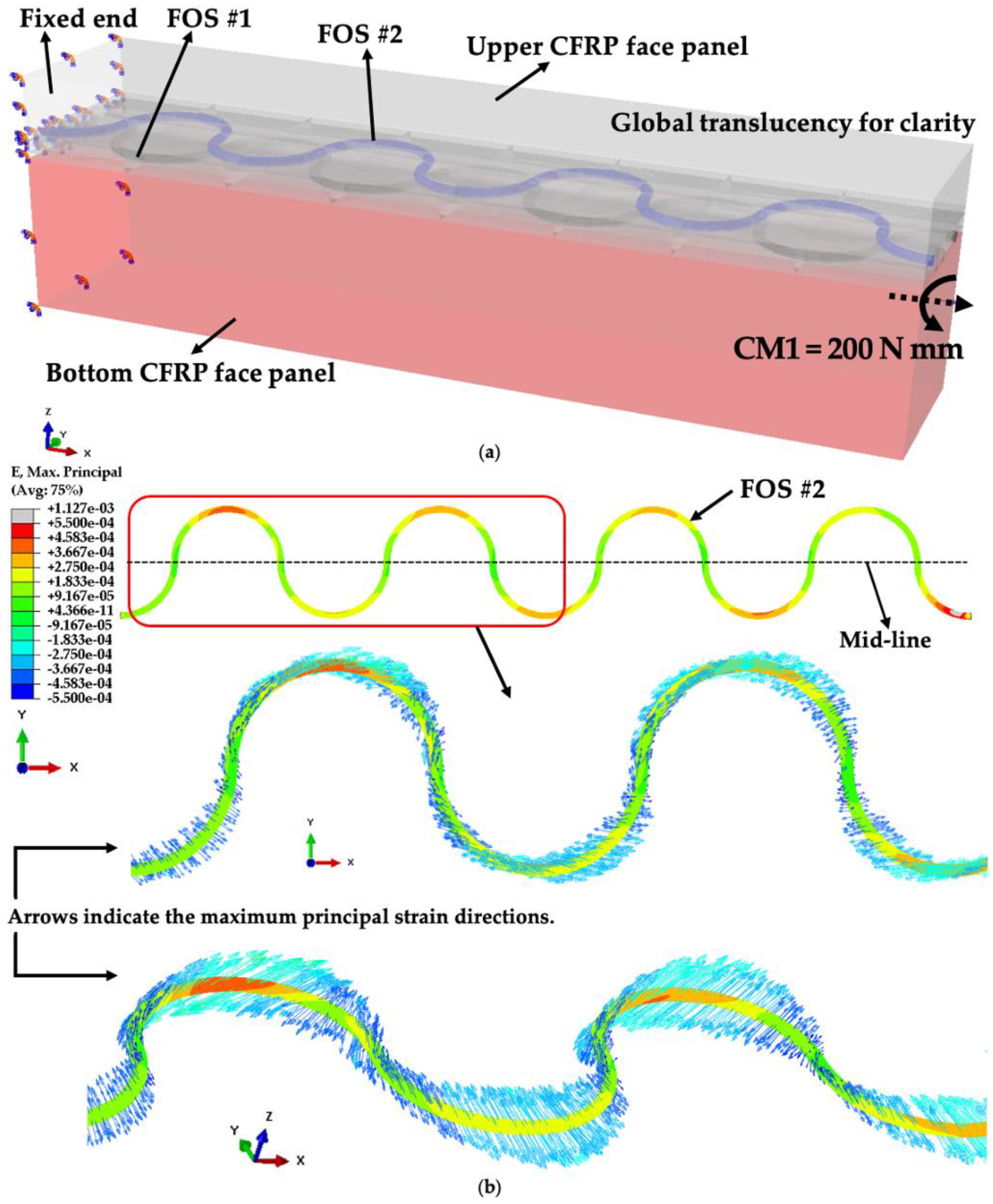
One end of the numerical model (YZ-bottom-end-plane) is fixed, while at the other end (YZ-top-end-plane), an axial displacement along the Z-axis on the top row of nodes (U3 = −0.5 mm) is enforced, as shown in Figure 6.

2.4.3. Torsion

A reference point (RP-1) has been created on the YZ-top-end-plane, right in the middle, as shown in Figure 7. Then, a coupling constraint covering all six degrees of freedom links the plane to the RP-1. Finally, torsion is applied to the RP-1 by setting a moment around the X-axis (CM1 = 200 N mm), while the YZ-bottom-end-plane is fixed.

3. Results and Discussion

The aim of embedding FOSs into composite structures is to enhance their protection and monitor strains. However, embedded FOSs are “foreign” materials whose diameters (e.g., 125 µm) are much larger than that of carbon fibers (e.g., 5~10 µm) [19], thereby inevitably resulting in perturbed strain states around them. They could act as internal flaws that might initiate damage (e.g., debonding and delamination) and cause premature failures [1,2,3,4,5].
In view of this, embedment influences on the mechanical behavior of composite structures should be considered first. Then, it is appropriate to discuss what monitoring information can be obtained from novel placement strategies under various boundary conditions. Finally, a balance among mechanical influences, sensing functions, and monitoring coverage should be stricken. These three points will be discussed in the following.

3.1. Mechanical Considerations Pertaining to Sensor Embedment

As presented in previous research works [1,2,3], three key sinusoidal placement parameters (Figure 8 and Equations (1) and (2)) need to be carefully optimized. For example, larger amplitudes (V3) are desirable for larger monitoring coverage but smaller edge gaps (V1) are more likely to initiate delamination/debonding at lower stress levels than those in specimens without embedded FOSs [3]. When monitoring principal strains under uniaxial loadings, FOSs are required to be placed as straight as possible following the loading direction [1], while smaller period sizes (V4) are expected to help monitor shear strains when under torsion. In this article, the set of parameters (V1 = 0.375, V3 = 0.625, and V4 = 2.500, as illustrated in Figure 3) are chosen based on previous studies [1,2,3], assuming that they have been optimized preliminarily, and the goal is to further identify the resulting strain patterns from them in various loading cases.
b = 2 × 1 + 2 × V3.
L = n × V4.
In Figure 8 and Equations (1) and (2), V1, V3, and V4 denote the edge gap, amplitude, and period size of a sinusoidal placement pattern, respectively, while b and L represent the width and length of the host material, respectively, in which L is equal to the product of n (the number of full periods) and V4 [3]. Each sinusoidal FOS is modeled with four full periods (n = 4) to predict the strain variations internal to specimens along the X-axis under three loading conditions. The mid-line is a construction line at half the width (0.5 b).
The intrusive impact of embedded FOSs (discussed in Section 1) can be alleviated by embedding FOSs into structural adhesive joints, as no wavy reinforcing fiber or resin pocket is created [30,31]. By monitoring the stress/strain fields inside adhesive joints, in-service structural mechanical behavior, as well as manufacturing quality, can also be evaluated by capturing any strain gradient developed [30,31]. Therefore, in this study, distributed FOSs are modeled as being embedded into an adhesive joint between two CFRP laminates, which is also consistent with previous studies [1,2,3].
A configuration of 3-ply laminate/adhesive joint/8-ply laminate (discussed in Section 2.1) is designed for the following two reasons: (1) to simulate a more realistic bonded assembly used in wind turbine blades [12], where the thickness and LSS of one laminate on one side of the adhesive joint is usually different from that on the other side—for example, a bonded assembly of spar and skin; (2) to monitor the resulting strains from various loading cases, FOSs should be away from the neutral plane.
In addition, to alleviate the effect of warping, a symmetric quasi-isotropic LSS is designed for the 8-ply laminate ([45/0/−45/90]s), while symmetric LSS for the 3-ply laminate ([0/90/0]).

3.2. Strain Sensing Information from Numerical Results
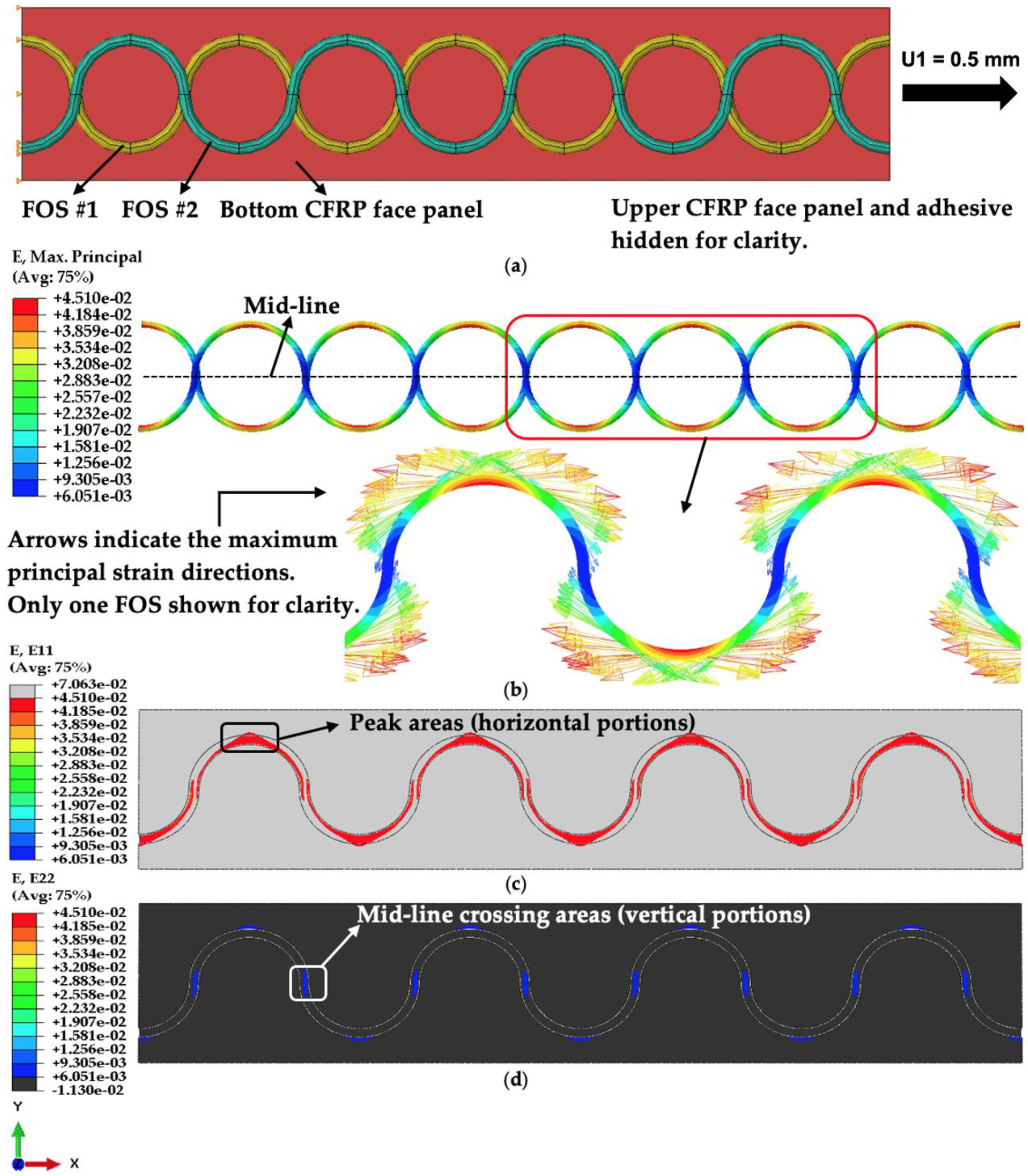
The following numerical results are evaluated and discussed based on multi-directional strain patterns, namely longitudinal (εx = E11), transverse (εy = E22), and shear (γxy = E12; γxz = E13; γyz = E23) strains, in the three quasi-static loading cases. The strain contours along the FOS cores can be regarded as the strains measured by FOSs in service. Note that the load levels chosen in Section 2.4 are for demonstration and are not necessarily based on experimental results or in-service data.

3.2.1. Tension

As shown in Figure 9b, in this loading case (tension along the X-axis), the maximum principal strain directions of FOS cores follow the tangents of their paths. In peak areas (horizontal portions), where the tangents are parallel to the X-axis (the loading direction), the longitudinal strain component (E11) dominates, whose value is much higher than other strain components. For example, the E11 in peak areas is more than five times the E22 in mid-line crossing areas (vertical portions), arising from transverse contraction. This strain pattern remains consistent throughout the whole longitudinal span.
Compared to strains in host materials, the strains measured in FOS peak areas (Figure 9b) can represent the E11 component of the corresponding FOS embedment areas in epoxy adhesive (Figure 9c); similarly, the strains measured in mid-line crossing areas in Figure 9b correspond to those in Figure 9d, the E22 component. Negligible discrepancies (around 5%) between each pair are due to the fact that there is a buffer layer of FOS coating between the FOS core and epoxy adhesive, whose modulus is closer to but not the same as that of epoxy adhesive.
The resulting strain contours from the tension case (Figure 9) are in accordance with expectations and confirm the strain-measuring advantages of the dual-antiphasic sinusoidal placement pattern by illustrating the capabilities of dual-sinusoidal FOSs to sense different strain components along their paths and to provide complementary strain-measuring areas. If structures are primarily under tension, where the main target should be to monitor longitudinal strains more accurately, it is desirable that the sinusoidal FOSs are stretched along the loading direction as much as possible to have larger period sizes.

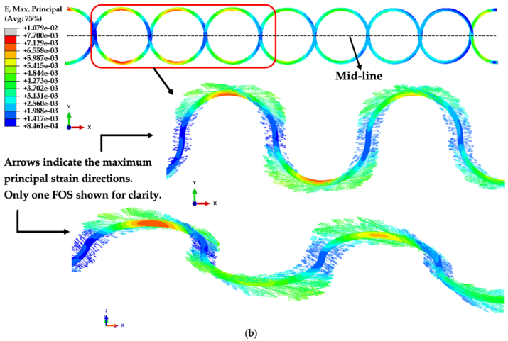
3.2.2. Cantilever Bending

In this loading case, FOSs and adhesive layers are on the tensile side, as shown in Figure 10a. From Figure 10b, it can be seen that both axial strains (due to bending moment) and vertical shear strains contribute to the maximum principal strains of the FOS cores. At the fixed end, where the model bears the highest bending moment, the strain pattern is similar to that in the tension case. E11 dominates the peak areas, and its value is over four times the E22 in mid-line crossing areas. Gradually moving to the loading end, the dominance of E11 fades away, and the difference between them diminishes. At the loading end, the strain values read in the FOS vertical portions are even higher than those in the peak areas.
Compared to strains in host materials, at the fixed end, observations are similar to those in the tension case: the peak-area strains of FOS cores, shown in Figure 10b, can represent the E11 component of the corresponding areas in epoxy adhesive; the strains measured in mid-line crossing areas correspond to the E22 component of epoxy adhesive. However, gradually moving to the loading end, the dominant effect from bending moment fades away, and the model is in more complex strain states. Thus, it becomes difficult to relate the strains in FOS cores to strain components in host materials.
Similar to those in Section 3.2.1, the strain contours of FOS cores under cantilever bending (Figure 10b) can also illustrate the capabilities of dual-sinusoidal FOSs. In comparison, the resulting strain pattern from cantilever bending varies when gradually moving from the fixed end to the loading end, which distinguishes cantilever bending from tension. Although the strain pattern is consistent with what is expected, to more accurately interpret the strains measured along dual-sinusoidal FOSs under cantilever bending, especially in areas closer to the loading end, further correlations need to be established between numerical and experimental results.

3.2.3. Torsion

Numerical results from this loading case are evaluated and discussed based on the strain contours of FOS #2, as it is closer to the surface and has higher strain values than FOS #1. Figure 11b shows that FOS #2 under torsion is in complex three-dimensional strain states, where both in-plane and out-of-plane strains contribute to its maximum principal strains. For example, as shown in Figure 11c, the E23 strain component dominates in mid-line crossing areas at both ends, while in the center of the longitudinal span, positive and negative E23 strain components cancel out. In peak areas, the maximum principal strains result from both E13 and E11 strain components, which are illustrated in Figure 11d,e, respectively. Furthermore, three major patterns can be derived from the comparison between the maximum principal strain values in peak areas and those in vertical portions in Figure 11b: (1) at the loading end, the peak-area-to-vertical-portion ratio is around 1.5; (2) in the center of the longitudinal span, the values in peak areas are more than four times those in vertical portions; (3) the fixed end sees a less than threefold difference between them.
However, due to the complex strain states, it is difficult to relate the strains along the FOS cores to strain components in host materials.
The resulting strain contours of the FOS cores from torsion agree with expectations and show specific patterns that are different from those in tension and cantilever bending. While the results from this loading case can also imply the capabilities of dual-sinusoidal FOSs to sense different strain components along their paths and to provide complementary strain measuring areas, to more accurately interpret the strains measured along sinusoidal FOSs under torsion, further correlations need to be established between numerical and experimental results.
To go somewhat toward the validation of the concept suggested in the current article, an analytical approach has been suggested in previous work (3). Glass-fiber-reinforced composite material manufactured by pultrusion was considered and specimens (800 mm × 30 mm × 20 mm) were cut for bending tests. Fiber-optic sensors (diameter 125 microns 80 mm microns acrylate coating) were embedded as double-sinusoids (Figure 12). The specimens were heated at 40 °C to ensure appropriate bonding and then mechanically tested under 3-point bending and displacement controlled. FOS signals were recorded continuously with a LUNA OBR-4600-type optical back-scattering reflectometer (LUNA company, Roanoke, VA, USA).
It is worthwhile to note that the analytical result listed hereafter is not a full validation of numerical modeling but is a verification that the assumptions upstream of our new concept are making sense. Sinusoidal placement has the advantage of covering a much larger surface of a structure with a single optical-fiber sensor than a linearly placed FOS by recording strain in the three dimensions. This tendency is much more reinforced when using double-sinusoid placement. The result pictured in Figure 13 emphasizes strain measurements under bending obtained with the double-sinusoid placement technique. It is clearly shown that both FOSs are able to measure bending same-strain signals (Both FOSs shows are recording the same value around 1200 µm/m), which is an encouraging result. However, we should avoid excessive satisfaction since additional experiments and deep analysis have to be performed so that the described concept of using double-sinusoid placed sensors be more convincing, either for scientists or users.

3.3. Discussion

The resulting strain contours from all three loading cases studied agree well with expectations. The strain-measuring advantages of the sinusoidal pattern compared to a linear placement pattern can be illustrated by the fact that sinusoidal FOSs can sense different strain components along their paths and obtain distinct strain contours from various loading conditions. Moreover, dual-sinusoidal placement, compared to a single-sinusoidal placement, can effectively further increase monitoring coverage by providing complementary strain-measuring areas.
When structures are primarily under in-plane strains, the strains measured along dual-sinusoidal FOSs can be readily related to the corresponding strain components of host materials, while if out-of-plane shear strains become dominant or comparable to in-plane strains, it becomes difficult to do so because the structures are in more complex strain states.
In order to more accurately interpret the strains measured by FOSs and reflect the mechanical responses of host materials, further correlations need to be established between numerical and experimental results. They must also include, among others, micromechanical analyses at the interfaces between FOSs and composite constituents [32], as well as the multi-physics (mechanical, thermal, and electrical) implications on real smart structures [33]. These additional aspects to this work can give readers a more comprehensive understanding of how complex the problem is to be solved at the scale of real structures. Last but not least, the current article is focusing solely on the use of optical fibers as strain sensors to monitor strain well below the onset of strain. Other articles that have provided research are using various techniques to monitor damage (for example, [34,35,36,37,38,39]) whereas others are using sinusoidal placements of FOSs
Since dual-sinusoidal placement has the potential for full coverage of a composite structure, it is worth studying its application in increasingly larger specimens. As discussed in Section 3.1, the three in-plane placement parameters have influences on the mechanical behavior and functionality of smart structures; therefore, the key parameters need to be further optimized quantitatively as functions of the length and width of the host composite structures by conducting parametric studies to strike a balance between mechanical influences and sensing functions. For example, if long blades are considered under uniaxial tensile loads only, larger period sizes (V4) of FOSs are desirable because the main target in this case is to more accurately measure longitudinal strains, while alleviating strain concentrations due to embedded sinusoidal FOSs. Under torsion, while smaller period sizes (V4) and larger amplitudes (V3) are required for monitoring shear strains, sufficient edge gaps (V1) need to be guaranteed to avoid initiating premature delamination/debonding.
On the other hand, the out-of-plane placement of FOSs also needs attention. For example, an overlap of two sinusoidal FOSs in the thickness direction, which results in stress concentrations, is a main drawback and must be assessed.
The concept described in the current article as applied science is new, and let us say, it is at very low TRL (around 1 to 2). The objective upstream is to conduct exploratory deep research that can lead us to TRL 3 to 4, that can be convincing about the potential of offshore engineering to use it, and raise the research issues (analytical and numerical) that have to be solved and the guidelines for future integrated research project that can lead us from the proof of concept (this current article) to the pilot wind-blade that is reliable enough for industrial use in the offshore industry. The pathway toward this goal is very complex and tedious, as the challenges are numerous. So many points need to be worked out, but not at this stage, unfortunately. For example, the effects of the interface FOS-Ply were not considered—neither were the rheology effects (epoxy behavior), the effects of fiber-optic coating (acrylate or polyimide), contact fatigue behavior, micromechanics, etc.

4. Conclusions

To gather maximum information concerning the health conditions of structures under various loading conditions, as well as to enhance the protection of sensors from external harsh environments, it is desirable to embed sensors into structures. Considering the three main drawbacks of SHM through embedded distributed FOSs, as listed in Section 1, FOSs are modeled as being embedded inside an adhesive joint between two CFRP laminates in a dual-sinusoidal pattern. The main conclusions are:
  • Based on an optimized set of sinusoidal placement parameters proposed in previous works [1,2,3], finite element modeling under various boundary conditions has been conducted.
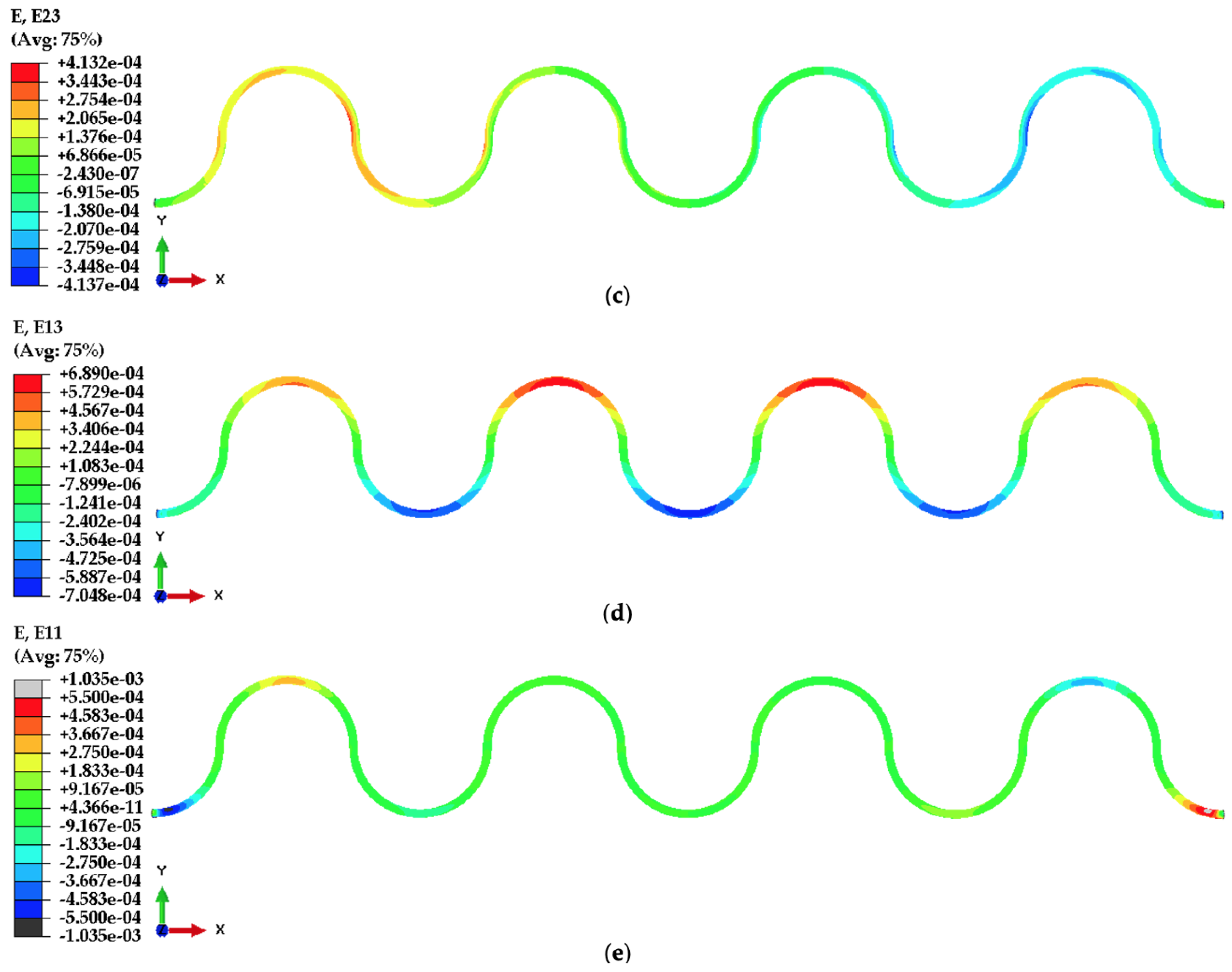
  • Numerical results have helped further identify the resulting strain patterns and sensing capabilities from the optimized dual-sinusoidal placement of FOSs in three loading cases.
  • Nonetheless, it is worth noting that the modeling suggested is nothing more than a proof of concept that targets the best combination of variables, which will be further applied in a more realistic project related to real smart composite structures for offshore applications.
  • The responses of dual-sinusoidal FOSs under tension, bending, and torsion agree with expectations and demonstrate their strain-measuring advantages.
  • On the one hand, dual-sinusoidal placement retains the multi-axial strain-sensing capability from a single-sinusoidal placement; on the other hand, it provides enlarged strain-measuring areas.
  • The strain measurements along dual-sinusoidal FOSs can be readily related to the corresponding strain components of host structures if the structures are primarily under in-plane strains; if out-of-plane shear strains become dominant or comparable to in-plane strains, it becomes difficult to do so.
  • Based on this research work, the following future studies are worth conducting: (1) correlations between numerical and experimental results to be further established to more accurately interpret the strains measured by FOSs and reflect the mechanical responses of host materials; (2) the three key in-plane placement parameters to be further optimized quantitatively as functions of the length and width of host composite structures by conducting parametric studies to strike a balance between their resulting mechanical influences and sensing functions; (3) the out-of-plane placement of dual-sinusoidal FOSs to be further characterized. Note also that the thickness of adhesive joints (elasto-plastic effects) and temperature play an important role in strain measurements, and they will be addressed in further studies.

Author Contributions

conceptualization, M.D.-H.; methodology, H.S., M.D.-H. and V.C.; formal analysis, M.D.-H., V.C. and H.S.; writing—original draft preparation, H.S.; writing—review and editing, M.D.-H. and V.C. All authors have read and agreed to the published version of the manuscript.

Funding

This research received no external funding.

Data Availability Statement

Data contained within the article will be made available on request.

Conflicts of Interest

The authors declare no conflict of interest.

References

  1. Drissi-Habti, M.; Raman, V.; Khadour, A.; Timorian, S. Fiber Optic Sensor Embedment Study for Multi-Parameter Strain Sensing. Sensors 2017, 17, 667. [Google Scholar] [CrossRef] [PubMed]
  2. Raman, V. A Smart Composite Based on Carbon Fiber and Epoxy Matrix for New Offshore Wind-Turbines. Multi-Scale Numerical and Analytical Modelings. Ph.D. Thesis, École Centrale de Nantes, Nantes, France, 2017. [Google Scholar]
  3. Raman, V.; Drissi-Habti, M.; Limje, P.; Khadour, A. Finer SHM-Coverage of Inter-Plies and Bondings in Smart Composite by Dual Sinusoidal Placed Distributed Optical Fiber Sensors. Sensors 2019, 19, 742. [Google Scholar] [CrossRef]
  4. Drissi-Habti, M.; Abhijit, N.; Sriharsha, M.; Carvelli, V.; Bonamy, P.-J. Concept of Placement of Fiber-Optic Sensor in Smart Energy Transport Cable under Tensile Loading. Sensors 2022, 22, 2444. [Google Scholar] [CrossRef] [PubMed]
  5. Drissi-Habti, M.; Neginhal, A.; Manepalli, S.; Carvelli, V. Fiber-Optic Sensors (FOS) for Smart High Voltage Composite Cables—Numerical Simulation of Multi-Parameter Bending Effects Generated by Irregular Seabed Topography. Sensors 2022, 22, 7899. [Google Scholar] [CrossRef] [PubMed]
  6. Drissi-Habti, M.; Raman, V. Fatigue Behavior of Smart Composites with Distributed Fiber Optic Sensors for Offshore Applications. J. Compos. Sci. 2022, 6, 2. [Google Scholar] [CrossRef]
  7. Schreyer, F.; Luderer, G.; Rodrigues, R.; Pietzcker, R.C.; Baumstark, L.; Sugiyama, M.; Brecha, R.J.; Ueckerdt, F. Common but Differentiated Leadership: Strategies and Challenges for Carbon Neutrality by 2050 across Industrialized Economies. Environ. Res. Lett. 2020, 15, 114016. [Google Scholar] [CrossRef]
  8. US Department of Energy. Levelized Costs of New Generation Resources in the Annual Energy Outlook 2022; US Department of Energy: Washington, DC, USA, 2022.
  9. Joyce, L.; Feng, Z. Global Wind Report 2022. Available online: https://gwec.net/global-wind-report-2022/ (accessed on 15 July 2023).
  10. Bilgili, M.; Alphan, H. Global Growth in Offshore Wind Turbine Technology. Clean Technol. Environ. Policy 2022, 24, 2215–2227. [Google Scholar] [CrossRef]
  11. Mishnaevsky, L.; Branner, K.; Petersen, H.N.; Beauson, J.; McGugan, M.; Sørensen, B.F. Materials for Wind Turbine Blades: An Overview. Materials 2017, 10, 1285. [Google Scholar] [CrossRef]
  12. Brondsted, P.; Nijssen, R.P.L.; Goutianos, S. (Eds.) Advances in Wind Turbine Blade Design and Materials; Woodhead Publishing Series in Energy; Elsevier Editora: Amsterdam, The Netherlands, 2023. [Google Scholar]
  13. Raman, V.; Drissi-Habti, M.; Guillaumat, L.; Khadhour, A. Numerical Simulation Analysis as a Tool to Identify Areas of Weakness in a Turbine Wind-Blade and Solutions for Their Reinforcement. Compos. Part B Eng. 2016, 103, 23–39. [Google Scholar] [CrossRef]
  14. Drissi-Habti, M.; El Assami, Y.; Raman, V. Multiscale Toughening of Composites with Carbon Nanotubes—Continuous Multiscale Reinforcement New Concept. J. Compos. Sci. 2021, 5, 135. [Google Scholar] [CrossRef]
  15. Zhou, G.; Sim, L.M. Damage Detection and Assessment in Fibre-Reinforced Composite Structures with Embedded Fibre Optic Sensors-Review. Smart Mater. Struct. 2002, 11, 925. [Google Scholar] [CrossRef]
  16. Lopez-Higuera, J.M.; Rodriguez Cobo, L.; Quintela Incera, A.; Cobo, A. Fiber Optic Sensors in Structural Health Monitoring. J. Light. Technol. 2011, 29, 587–608. [Google Scholar] [CrossRef]
  17. He, J.; Yang, J.; Wang, Y.; Waisman, H.; Zhang, W. Probabilistic Model Updating for Sizing of Hole-Edge Crack Using Fiber Bragg Grating Sensors and the High-Order Extended Finite Element Method. Sensors 2016, 16, 1956. [Google Scholar] [CrossRef]
  18. Glišić, B.; Inaudi, D. Fibre Optic Methods for Structural Health Monitoring; John Wiley & Sons: Chichester, UK; Hoboken, NJ, USA, 2007; ISBN 978-0-470-06142-8. [Google Scholar]
  19. Di Sante, R. Fibre Optic Sensors for Structural Health Monitoring of Aircraft Composite Structures: Recent Advances and Applications. Sensors 2015, 15, 18666–18713. [Google Scholar] [CrossRef]
  20. Chung, D.D.L. 10—Self-Sensing Structural Composites in Aerospace Engineering. In Advanced Composite Materials for Aerospace Engineering; Rana, S., Fangueiro, R., Eds.; Woodhead Publishing: Sawston, UK, 2016; pp. 295–331. ISBN 978-0-08-100939-0. [Google Scholar]
  21. Lammens, N.; Luyckx, G.; Voet, E.; Van Paepegem, W.; Degrieck, J. Finite Element Prediction of Resin Pocket Geometry around Embedded Optical Fiber Sensors in Prepreg Composites. Compos. Struct. 2015, 132, 825–832. [Google Scholar] [CrossRef]
  22. Güemes, A.; Fernández-López, A.; Díaz-Maroto, P.F.; Lozano, A.; Sierra-Perez, J. Structural Health Monitoring in Composite Structures by Fiber-Optic Sensors. Sensors 2018, 18, 1094. [Google Scholar] [CrossRef] [PubMed]
  23. Hartog, A.H. An Introduction to Distributed Optical Fibre Sensors; CRC Press: Boca Raton, FL, USA, 2017; ISBN 978-1-315-11901-4. [Google Scholar]
  24. Grattan, K.T.V.; Sun, T. Fiber Optic Sensor Technology: An Overview. Sens. Actuators Phys. 2000, 82, 40–61. [Google Scholar] [CrossRef]
  25. Bergmayr, T.; Winklberger, M.; Kralovec, C.; Schagerl, M. Structural Health Monitoring of Aerospace Sandwich Structures via Strain Measurements along Zero-Strain Trajectories. Eng. Fail. Anal. 2021, 126, 105454. [Google Scholar] [CrossRef]
  26. Janetzko-Preisler, A.; Wolf-Monheim, F.; Souschek, R.; Kaiser, D.; Wojtczyk, R.; Dafnis, A.; Schröder, K.-U.; David, W.; Zandbergen, P. Integration and Evaluation of a Meander-Shaped Fibre-Optical Sensor in a GFRP Leaf Spring. MATEC Web Conf. 2021, 349, 3013. [Google Scholar] [CrossRef]
  27. Palmieri, L.; Schenato, L. Distributed Optical Fiber Sensing Based on Rayleigh Scattering. Open Opt. J. 2013, 7, 104–127. [Google Scholar] [CrossRef]
  28. Shivakumar, K.; Emmanwori, L. Mechanics of Failure of Composite Laminates with an Embedded Fiber Optic Sensor. J. Compos. Mater. 2004, 38, 669–680. [Google Scholar] [CrossRef]
  29. Available online: https://www.3ds.com/support/hardware-and-software/simulia-system-information/abaqus-2021/ (accessed on 28 July 2023).
  30. Murayama, H.; Kageyama, K.; Uzawa, K.; Ohara, K.; Igawa, H. Strain Monitoring of a Single-Lap Joint with Embedded Fiber-Optic Distributed Sensors. Struct. Health Monit. 2012, 11, 325–344. [Google Scholar] [CrossRef]
  31. Canal, L.P.; Sarfaraz, R.; Violakis, G.; Botsis, J.; Michaud, V.; Limberger, H.G. Monitoring Strain Gradients in Adhesive Composite Joints by Embedded Fiber Bragg Grating Sensors. Compos. Struct. 2014, 112, 241–247. [Google Scholar] [CrossRef]
  32. Drissi-Habti, M.; Nakano, K. The Modelling of Shear Stress Transfer in Hi-Nicalonα-Si3N4 Ceramic-Matrix Composites by the Use of Micro-Indentation Tests. Compos. Sci. Technol. 1997, 57, 1381–1389. [Google Scholar] [CrossRef]
  33. Matine, A.; Drissi-Habti, M. On-Coupling Mechanical, Electrical and Thermal Behavior of Submarine Power Phases. Energies 2019, 12, 1009. [Google Scholar] [CrossRef]
  34. Sam-Daliri, O.; Faller, L.M.; Farahani, M.; Zangl, H. Structural health monitoring of adhesive joints under pure mode I loading using the electrical impedance measurement. Eng. Fract. Mech. 2021, 245, 107585. [Google Scholar] [CrossRef]
  35. Sam-Daliri, O.; Farahani, M.; Faller, L.M.; Zangl, H. Structural health monitoring of defective single lap adhesive joints using graphene nanoplatelets. J. Manuf. Process. 2020, 55, 119–130. [Google Scholar] [CrossRef]
  36. Yang, M.; Liu, Q.; Naqawe, H.S.; Fok, M.P. Movement detection in soft robotic gripper using sinusoidally embedded fiber optic sensor. Sensors 2020, 20, 1312. [Google Scholar] [CrossRef]
  37. Mekid, S.; Butt, A.M.; Qureshi, K. Integrity assessment under various conditions of embedded fiber optics based multi-sensing materials. Opt. Fiber Technol. 2017, 36, 334–343. [Google Scholar] [CrossRef]
  38. Gholamzadeh, B.; Nabovati, H. Fiber optic sensors. Int. J. Electron. Commun. Eng. 2008, 2, 1107–1117. [Google Scholar]
  39. Floris, I.; Adam, J.M.; Calderón García, P.A.; Sales Maicas, S. Fiber Optic Shape Sensors: A comprehensive review. Opt. Lasers Eng. 2021, 139, 1–17. [Google Scholar] [CrossRef]
Figure 1. Schematic of typical FOS cross-section.
Applsci 14 00932 g001
Figure 2. Numerical model with dual-sinusoidal FOSs embedded (dimensions in mm).
Applsci 14 00932 g002
Figure 3. Geometric characteristic of the numerical model (upper CFRP face panel and adhesive hidden for clarity, dimensions in mm).
Applsci 14 00932 g003
Figure 4. Mesh of the numerical model with dual-sinusoidal FOSs embedded.
Applsci 14 00932 g004
Figure 5. U1 = 0.5 mm applied on YZ-top-end-plane (arrows indicating the loading direction).
Applsci 14 00932 g005
Figure 6. U3 = −0.5 mm applied on the top row of nodes (arrows indicating the loading direction).
Applsci 14 00932 g006
Figure 7. Torsional moment applied to RP-1, linked to YZ-top-end-plane by coupling constraint.
Applsci 14 00932 g007
Figure 8. Three key placement parameters of a sinusoidal placement pattern [3].
Applsci 14 00932 g008
Figure 9. Tension loading case: (a) plan view of the numerical model under tension; (b) the maximum principal strain contours of FOS cores; (c) E11 strain component of epoxy adhesive; (d) E22 strain component of epoxy adhesive.
Applsci 14 00932 g009
Figure 10. Cantilever bending case: (a) Iso view of the numerical model under cantilever bending; (b) the maximum principal strain contours of FOS cores.
Applsci 14 00932 g010aApplsci 14 00932 g010b
Figure 11. Torsion case: (a) Iso view of the numerical model under torsion; (b) the maximum principal strain contours of FOS #2; (c) E23 strain component of FOS #2; (d) E13 strain component of FOS #2; (e) E11 strain component of FOS #2.
Applsci 14 00932 g011aApplsci 14 00932 g011b
Figure 12. Dual-sinusoidal FOSs’ placement embedded on a glass composite specimen [3].
Applsci 14 00932 g012
Figure 13. Bending strain measurement carried out with dual-sinusoidal FOSs alignment on a glass-fiber composite specimen [3].
Applsci 14 00932 g013
Table 1. Mechanical properties of the materials used in this research work [1].
MaterialsModulus (MPa)Poisson’s Ratio
CFRP laminaE1 = 103,000; E2 = 10,400; G12 = 54,000ν12 = 0.3; ν21 = 0.03
Epoxy resin35000.3
Acrylate27000.35
Silica glass72,0000.17
Disclaimer/Publisher’s Note: The statements, opinions and data contained in all publications are solely those of the individual author(s) and contributor(s) and not of MDPI and/or the editor(s). MDPI and/or the editor(s) disclaim responsibility for any injury to people or property resulting from any ideas, methods, instructions or products referred to in the content.

