Abstract
(1) Background: Lining voids and macroscopic water freezing are both prominent issues that threaten driving safety in high-speed railway tunnels. With the continuous expansion of the scale of high-speed rail tunnels in extremely cold areas in China, the issues of lining voids, water accumulation, and frost heaving have triggered heated discussions. The need to reveal the frost-heave mechanism is urgent. (2) Methods: Firstly, a simulation experiment of the frost heaving of accumulated water was carried out based on the discharge conditions of accumulated water. Secondly, a numerical model was used to study the evolution process of frost heaves caused by accumulated water in voids. Finally, a drainage coefficient was introduced to propose a method for calculating the frost-heave force of accumulated water in voids. (3) Results: The blockage of the drainage channel leads to the generation of frost-heave force; the freezing/thawing process of the void water develops from the thinnest part to the thickest part of the void edge, and the freeze/thaw cycle of the water body causes the frost-heave force to become greater and greater in the evacuated cavity. The higher the height and the closer the drainage channel is to the hollow bottom, the greater the frost-heave force when the accumulated water freezes. (4) Conclusions: When the evacuated water freezes, it develops from the thinner edge to the thicker center. The magnitude of the frost-heave force is affected by the freeze/thaw cycle, the height of the evacuated cavity, and the position of the drainage channel.
1. Introduction
High-speed rail tunnels in cold areas are a special type of tunnel that is very difficult to construct, operate, and maintain. Due to the obvious piston wind effect in high-speed railway tunnels, the temperature inside the tunnels fluctuates violently [1]. The length and extreme value of the negative temperature section are significantly longer than those of ordinary railway tunnels and highway tunnels. In addition, high-speed railway tunnels have faster driving speeds, higher safety requirements, and colder temperatures. The problem of freezing damage in regional tunnels is more complex, and the harm is more serious. The main manifestations of frost damage to tunnels in cold regions include ice accumulation on the tunnel bed, ice hanging on the lining, surface peeling, cracking, and the loss of blocks [2]. Among these, cracks, loss of blocks, and even damage caused by frost heaving can be caused by water accumulation behind the lining. The hazards of collapse are particularly serious. The conditions for freezing damage in tunnels are groundwater and negative temperatures. When preventing and controlling freezing damage, measures such as thermal insulation, heating and anti-freezing, anti-drainage optimization, and de-icing are usually implemented. However, these measures usually do not consider the short cycle. Problems include temperature fluctuations, high energy consumption [3,4], freezing of water in the drainage plate pores [5], potential safety hazards [6], and high costs [7,8,9].
Therefore, understanding the mechanism of frost-heave force caused by water accumulation in the lining and establishing models for its calculation and analysis are key prerequisites for the prevention and control of this type of frost damage. The accumulation of water in the cavity behind the lining is restricted in drainage during the freezing process, and the volume expands to generate frost-heave force [10]. Therefore, the formation and magnitude of the frost-heave force are directly related to the size and shape of the cavity, water drainage conditions, and temperature. The negative fluctuation process is directly related, and its formation mechanism and mechanical model are extremely complex. Zhang Yuwei [11] studied the influence of the surrounding rock temperature on frost-heave force through on-site measurements of the surrounding rock temperature and lining pressure. Zhang Mengya [12] studied tunnels in seasonally frozen soil areas and found that the frost-heave force decreased as the ambient temperature increased. Fan Lei [13] used the semi-formulaic and semi-empirical “elastic equivalent coefficient method” to calculate the magnitude of the frost-heave force of water accumulated between the lining and the surrounding rock. Zhang Jiabing [14] proposed a tunnel frost-heave force calculation model considering freeze/thaw damage and the lateral anisotropic characteristics of the surrounding rock. Cui Guangyao [15] comprehensively considered multiple factors, such as seasonal temperature changes and water body characteristics, and proposed a calculation model for the frost-heave force of freestanding water. The above studies all conducted certain analyses for the calculation of tunnel frost-heave force, but they did not comprehensively consider the effects of short-period temperature fluctuations, cavity size and shape, and water accumulation and drainage conditions on the frost-heave force.
In order to reveal the frost-heave mechanism of voids and accumulated water behind the lining of high-speed railway tunnels in cold regions, voids were first classified according to the positional relationship between voids and waterproof panels; then, the supply and discharge conditions of accumulated water in different types of voids were investigated, and the supply and drainage were studied experimentally to determine the effects of these conditions on the frost-heave force. Subsequently, circular wedge-shaped and flying-saucer-shaped deformation and freezing models of the tunnel vault were established, and the evolution process of frost heaving was analyzed based on the short-period temperature fluctuation conditions of the tunnel entrance section. Then, the drainage coefficient was introduced based on the relative position of the drainage channel and the void, and a calculation method for the frost-heave force caused by standing water was proposed to provide support for research on frost-heave prevention and control.
This study examines the influencing factors and influencing rules of the frost-heave force of void water in high-speed railway tunnels in cold areas, and it attempts to determine the formation mechanism of void water and frost heaving behind the lining. It aims to propose a criterion for the frost heaving of void water behind the lining. The core of this research is a monitoring system that uses real-time temperature field monitoring and tunnel disease characteristic parameters as basic data to predict and provide early warning of the degree and class of macroscopic freezing damage in the tunnel. It is helpful to propose targeted prevention and response measures to ensure the safety of various railway operations in cold areas and improve the efficiency of the operation and maintenance of various tunnels in cold areas.
2. Lining Void Form and Water Temperature Conditions
2.1. Lining Void Formation
The reasons for the formation of voids in the secondary lining of tunnels are very complex [16], mainly including the following: the excavation contour surface or the surface of the primary support is uneven, and the waterproof board is laid to form a cavity; the margin of the waterproof layer is insufficient, and the waterproof board cannot adhere to the surface of the primary support [17]; the workability of the concrete is poor, the density of steel bars in the lining is too high, the pumping pressure is insufficient, and the concrete cannot flow to the edge of the formwork [18]; the dry shrinkage of concrete and the influence of the longitudinal slope of the tunnel [19].
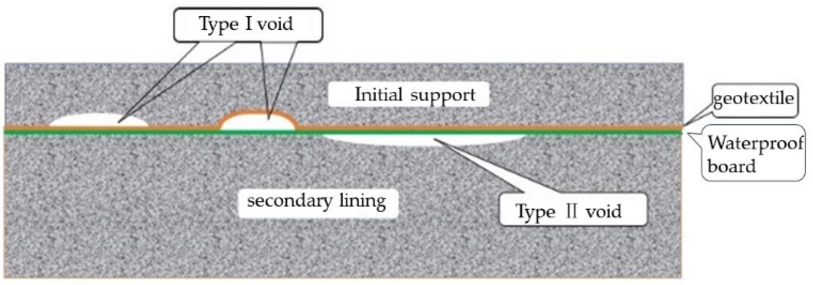
Voids behind the tunnel lining can be divided into two categories based on their positional relationship to the flashing: The voids between the initial support and the waterproof board are type I voids, such as the voids caused by an uneven excavation contour surface or primary support surface, insufficient margin of the waterproof layer, etc. The voids located between the secondary lining and the waterproof board are type II voids, such as voids caused by poor workability of the concrete, excessive density of steel bars in the lining, insufficient pumping pressure, dry shrinkage of concrete, etc., as shown in Figure 1.
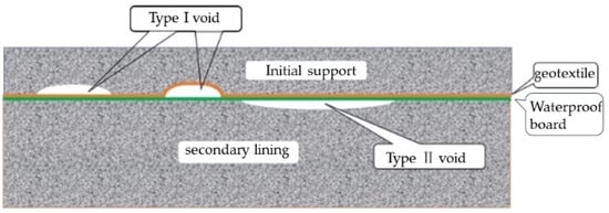
Figure 1.
Classification of voids behind the lining.
2.2. Conditions for Supply and Discharge of Empty Accumulated Water behind the Lining
For type I voids, because they are located outside the waterproof layer, the groundwater supply and discharge channels are open, and groundwater can penetrate the voids from any direction, leaving them in a state of water accumulation; when the water inside the voids freezes and expands, part of the accumulated water is discharged along the drainage channel.
For type II voids, they are located inside the waterproof layer, and the groundwater supply and discharge channels are fixed. The groundwater must pass through the waterproof layer through specific channels before it can flow into the hollowed cavities; when the water in the voids freezes and expands, if the supply and discharge channels are not frozen, part of the accumulated water will also be discharged; if the channels are frozen first, the accumulated water in the cavity cannot be discharged, and the frost heaving of the water body causes a large frost-heave force [20,21]. Therefore, the magnitude of the frost-heave force of void water is closely related to the freezing time of the excretion channel.
2.3. Short-Period Fluctuation Model of Lining Surface Temperature
In this study, the temperature field monitoring of high-speed railway tunnels in cold areas was carried out based on the Harbin–Mudanjiang high-speed railway, and the Hufengling Tunnel and Zhishan Tunnel, which have the highest altitude on the line, were selected for monitoring. In previous studies, the sine function with an annual cycle has been widely used to express tunnel temperature changes and has been used as a temperature load or boundary condition in model tests and numerical simulations, such as in the Hongfu Tunnel [22] and Galongla Tunnel [23], all using the temperature load function in the form of Equation (1):
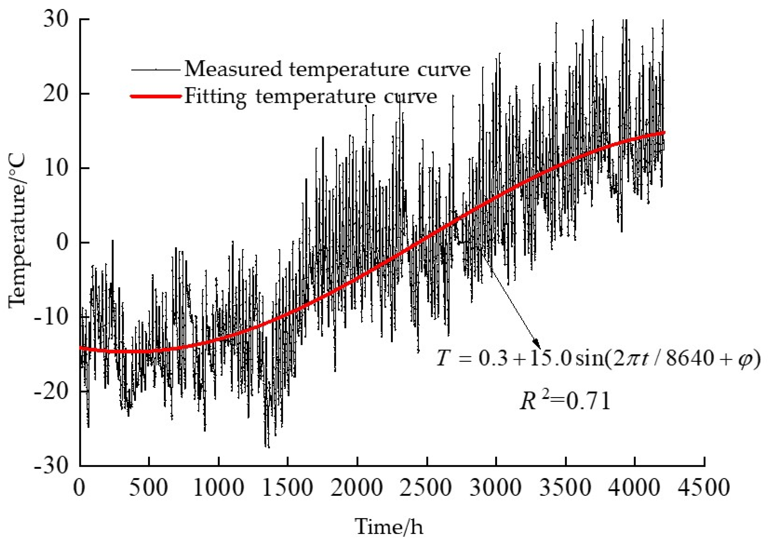
However, continuous measured results of the temperature field show that the diurnal temperature fluctuations caused by the alternation of day and night are very significant and widespread [24,25,26]. In on-site measurements, when the temperature difference in a day reaches more than 10 °C, it is considered that the temperature change on that day has obvious short-period temperature fluctuation characteristics. The temperature fluctuations at the entrance and exit of the Hufengling Tunnel reached 90 times in half a year, and at the entrance and exit of the Zhishan Tunnel the temperature fluctuated 130 times in half a year. The temperature curve of the entrance section of the Zhishan Tunnel from December 2018 to May of the following year is shown in Figure 2. When fitted by a sinusoidal function with an annual cycle, the correlation coefficient is 0.71, and it can be seen from the graph that the fitting using this function can only express the overall change trend of temperature and cannot express the characteristics of temperature fluctuations caused by the alternation of day and night.

Figure 2.
Zhishan Tunnel entrance temperature fitting.
Therefore, a sine function with a daily period was used to characterize the short−period fluctuations of the tunnel temperature field, as shown in Equation (2):
where t is the time (h), Tb is the amplitude of the short-period temperature change (°C), Tmb is the daily average temperature (°C), and is the daily initial phase (rad).
3. Simulation Analysis of the Formation Mechanism and Evolution Process of Frost-Heave Force
3.1. Effect of Excretion Conditions on Frost-Heave Force
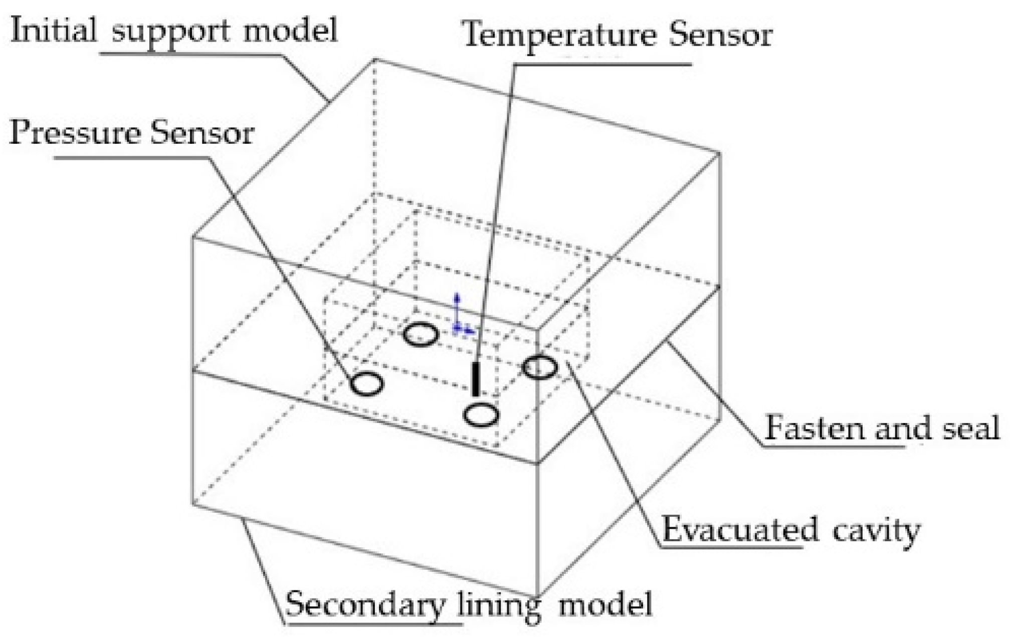
In order to explore the freezing process of the void water behind the lining and the formation mechanism of frost-heave force, a frost-heave test of void water behind the lining was carried out. The test model was composed of two concrete specimens with dimensions of 0.4 m × 0.4 m × 0.2 m, and the size of the hollow cavity was set to 0.2 m × 0.2 m × 0.1 m, as shown in Figure 3. A temperature sensor was embedded in the model to monitor whether the water in the cavity was frozen; a film pressure sensor was also installed to test the frost-heave force.

Figure 3.
Frost-heave test model for water accumulation in voids.
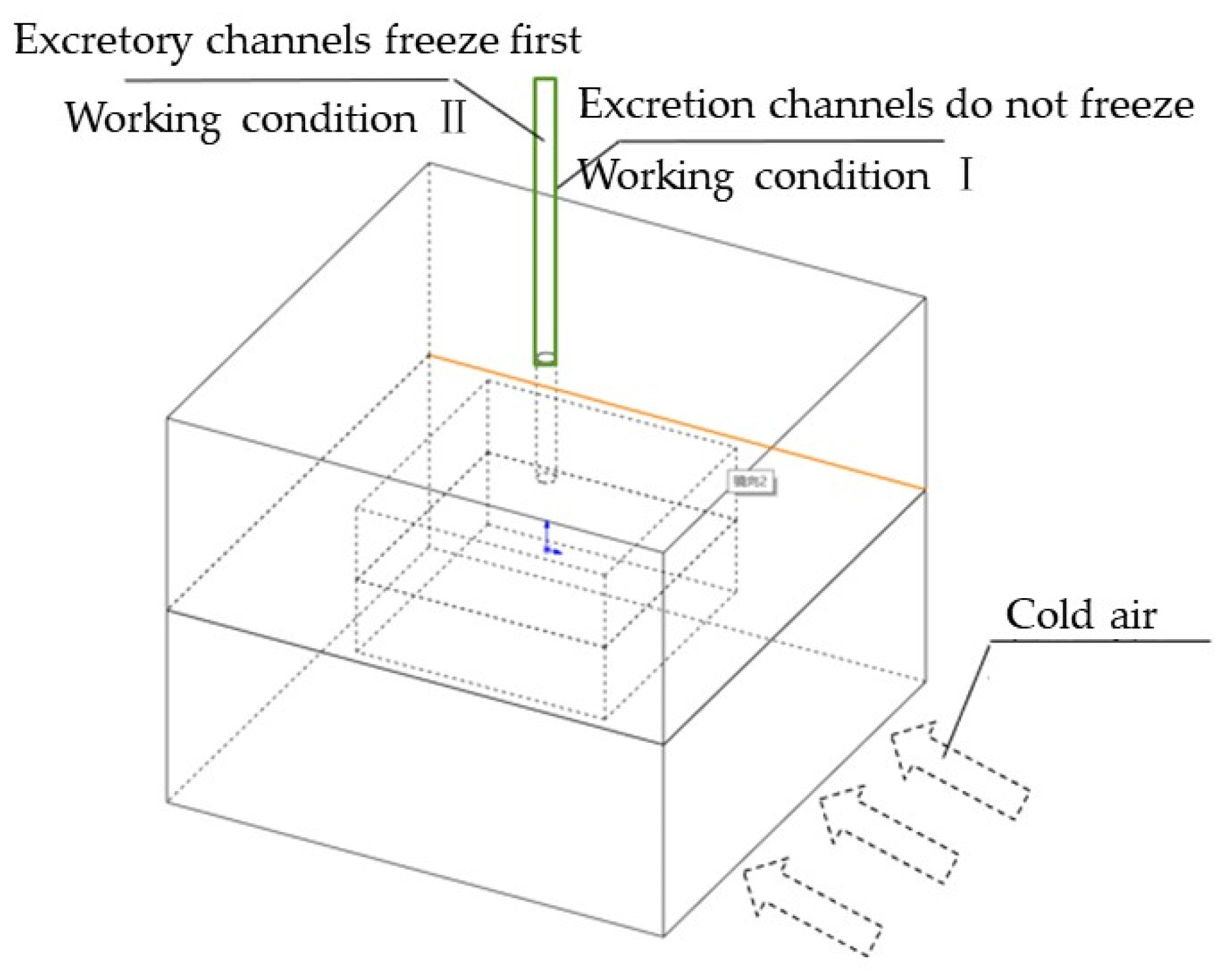
We set the test conditions according to the tunnel void form as follows: Working condition 1: during the freezing process of type I voids, the water supply and discharge channels do not freeze. Working condition 2: during the freezing process of type II voids, the water supply and drainage channels are frozen first, and the water body in the model freezes later, as shown in Figure 4.
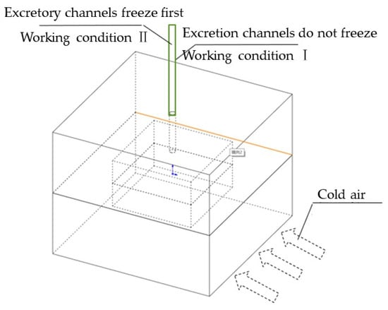
Figure 4.
Void water accumulation and frost-heave test conditions.
During the experiment, the top surface and four sides of the specimen were wrapped with insulation boards, leaving the bottom surface exposed to cold air. For working condition 1, the entire experimental process ensured that the drainage channel did not freeze and only the water in the cavity froze. For working condition 2, the drainage channel was frozen first, and then the water in the cavity was frozen.
By freezing the bottom of the specimen, it was found that, in working condition 1, the freezing process of the water body in the cavity developed from the bottom upward, and the frost-heave force in the cavity was almost zero; in working condition 2, the freezing process of the water body in the cavity also developed upward from the bottom of the cavity, and a large frost-heave force was generated in the cavity, with the average pressure reaching 0.16 MPa.
3.2. Numerical Simulation of Frost-Heave of Voided Water behind the Lining under Short-Period Temperature Fluctuation Conditions
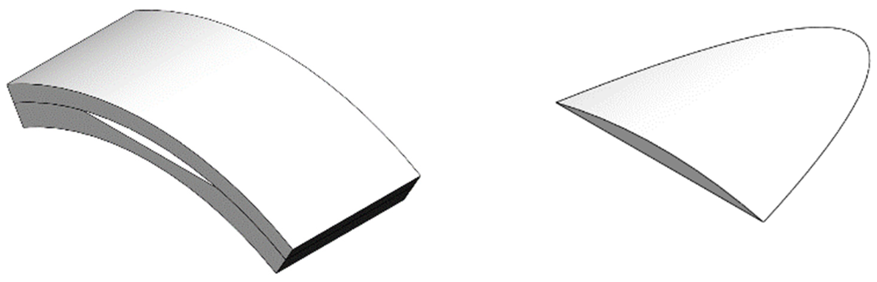
We used FLUENT simulation software based on the solidification/melting model to analyze the freezing process of the void water behind the lining under the condition of short-period fluctuations in the lining’s surface temperature. Considering that voids often occur in tunnel vaults, a model was established using vault voids as an example. Since voids often occur at the highest point of each mold lining near the end of the formwork, the void cavities formed by concrete pouring are mostly round wedge-shaped and flying-saucer-shaped, and we established circular wedge-shaped and flying-saucer-shaped void models.
3.2.1. Boundary Conditions
According to the temperature field monitoring results in the tunnel entrance section, considering a scenario where the short-period temperature amplitude of the tunnel reaches 15 °C under extreme conditions, the short-period fluctuation function of T0 = −5 + 15 × sin(2πt/24 + φ) was used as the temperature loading on the lining surface function, where the lining surface adopts a convective boundary.
3.2.2. Supply and Excretion Conditions
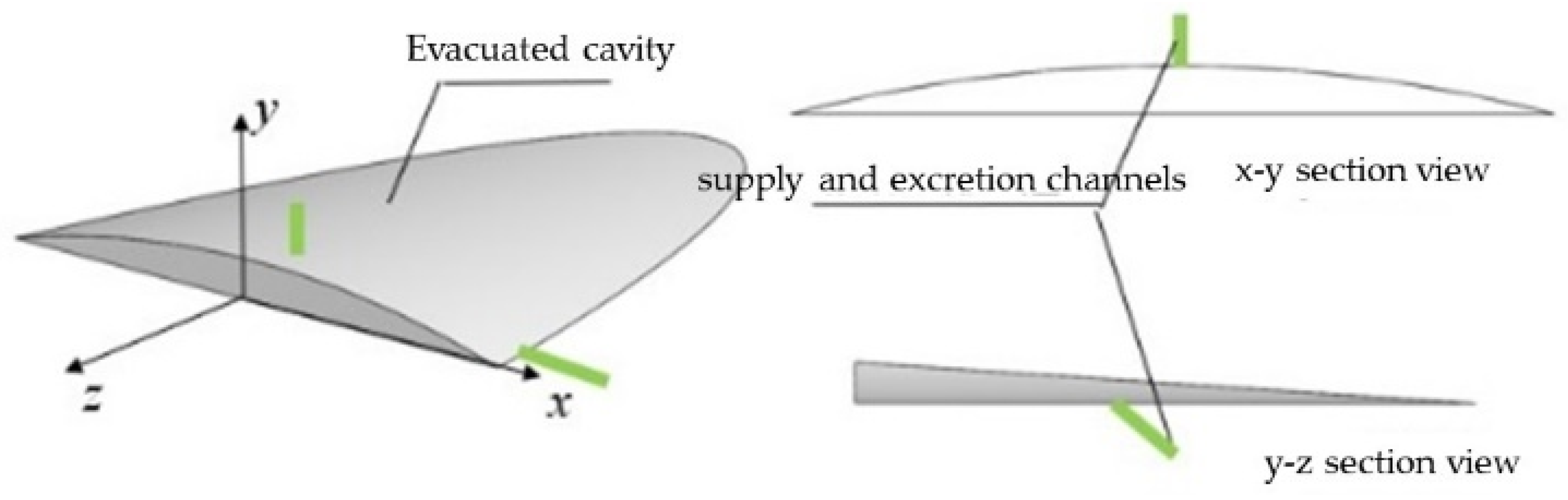
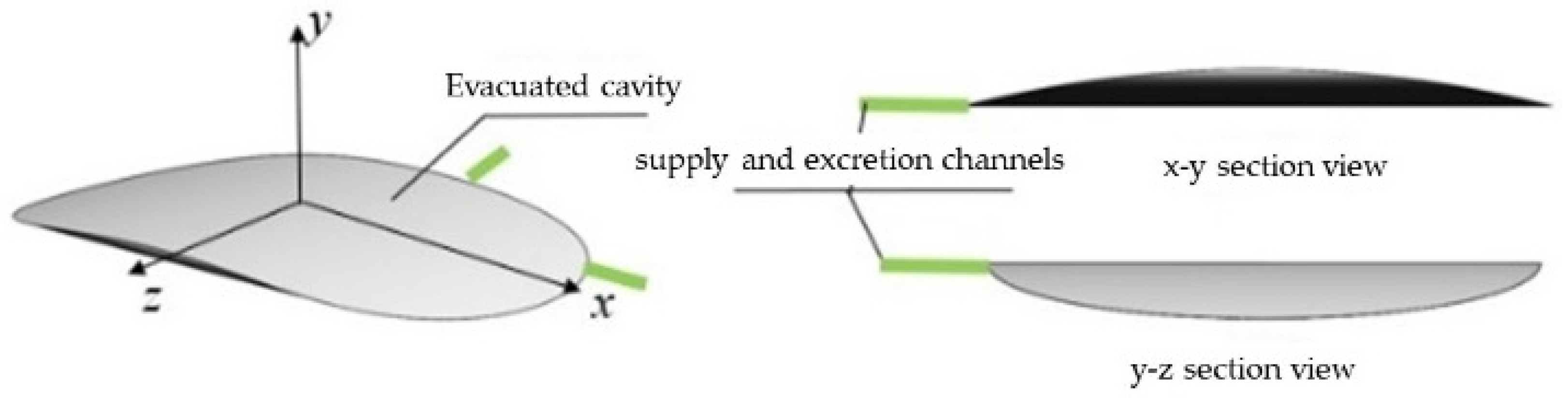
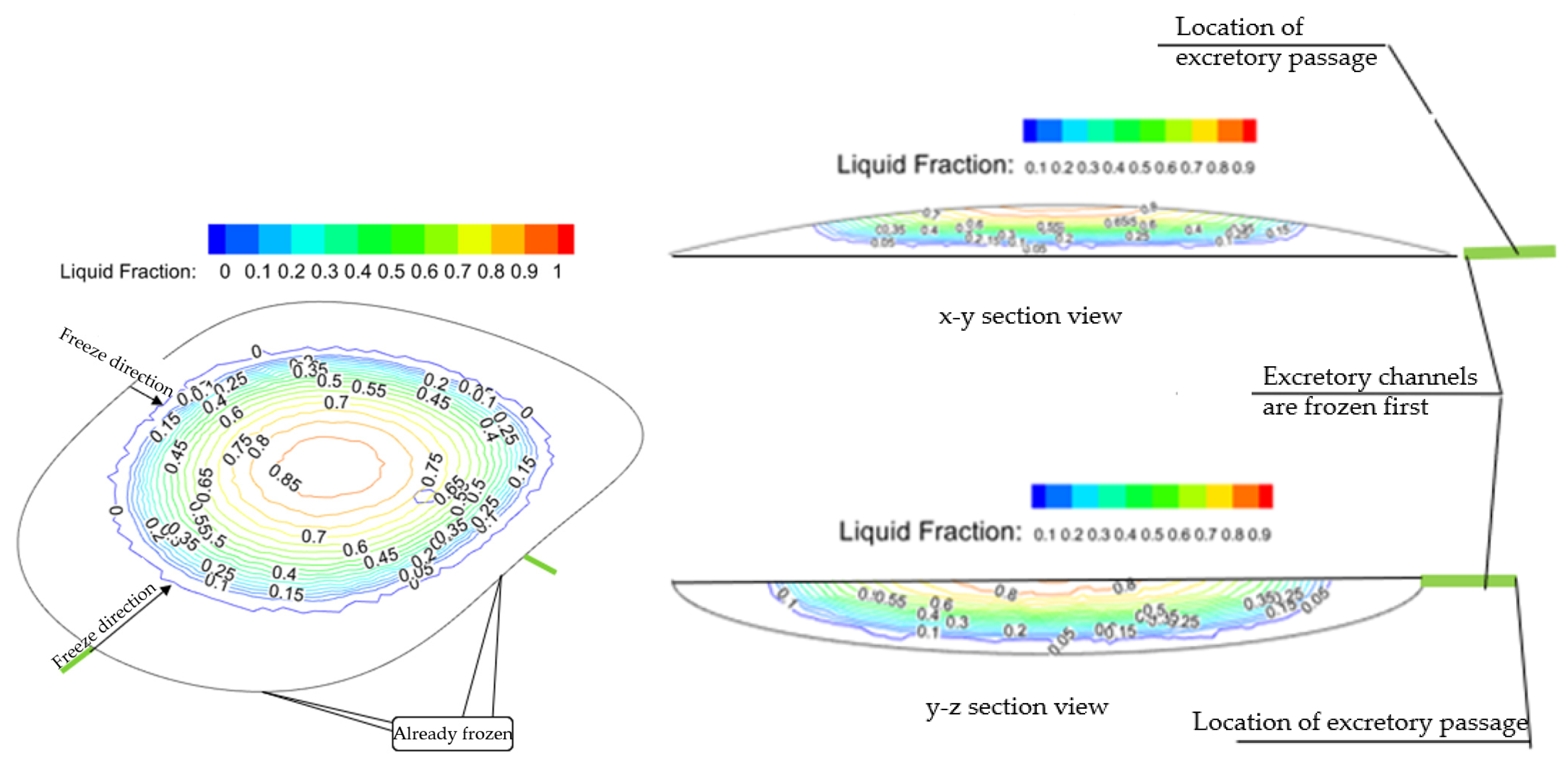
Based on the supply and discharge conditions of groundwater, two working conditions (top channel and lateral channel) were designed. In Figure 5 and Figure 6, the left side shows the shape of the hollow cavity, while the right side shows the location of the supply and excretion channels. In the x–y cross-sectional view in Figure 5, the drainage channel is located at the top of the hollow cavity, which corresponds to the working conditions in which water seeps into the cavity after the waterproof panel on the tunnel vault is damaged; in the y–z cross-section in Figure 5 and Figure 6, the drainage channel is located on the side of the cavity, corresponding to the tunnel arch waist and other parts. Water seepage enters the vault cavity along the waterproof board.
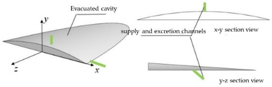
Figure 5.
Replenishment and discharge conditions for accumulated water in a circular wedge-shaped cavity.
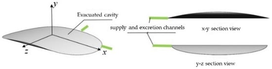
Figure 6.
Replenishment and discharge conditions of water accumulation in a flying-saucer-shaped cavity.
3.2.3. Grid and Parameters
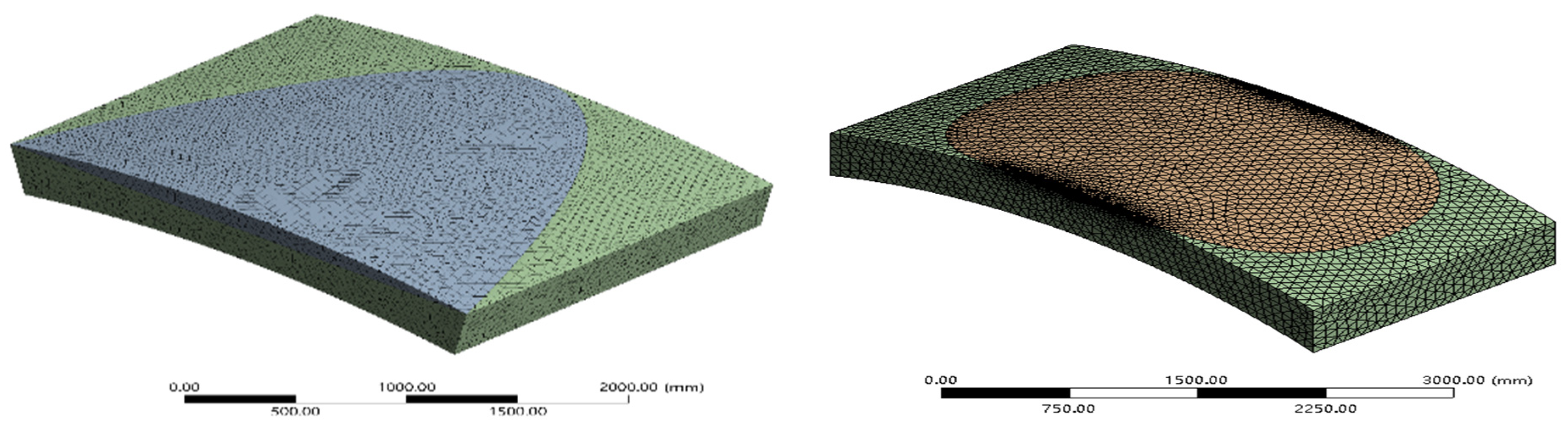
In order to reduce the calculation required by the model, the concrete- and water-filled cavities within the void range of the vault were selected as the research objects. The longitudinal length of the circular wedge-shaped voids and flying-saucer-shaped voids was 2.0 m, and the maximum height of the voids was 20 cm. A grid of the model is shown in Figure 7, and the parameters selected for simulation are shown in Table 1.
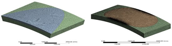
Figure 7.
Numerical simulation model grid.

Table 1.
Simulation parameters.
4. Results
4.1. Numerical Simulation Results
4.1.1. Freezing Process of Water Inside the Voids
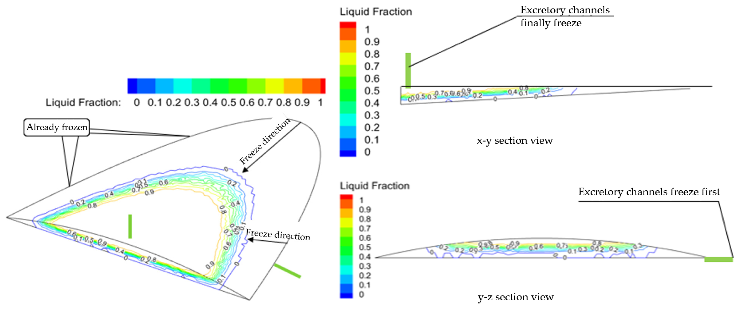
Figure 8 and Figure 9 show the freezing process of accumulated water in circular wedge-shaped voids and flying-saucer-shaped voids in the tunnel lining, respectively.
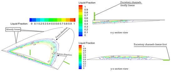
Figure 8.
Freezing process of circular wedge-shaped voids.
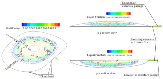
Figure 9.
Freezing process of flying-saucer-shaped voids.
It can be seen from Figure 8 that, during the cooling process, the freezing of the void water behind the lining starts from the edge of the void and develops from its thinnest part to the thickest part; during the freezing process, the freezing of the void water begins at the side of the void. The excretory channels (y–z cross-section) freeze first, and the channels at the top of the void freeze last (x–y cross-section).
It can be seen from Figure 9 that the freezing process of the void water behind the lining also starts from the edge of the void and develops from its thinnest part to the thickest part; during the freezing process, the freezing of the void water takes place at the side of the void (x–y cross-sectional view), and the excretory channels at the top (y–z cross-section view) are frozen first.
In general, the freezing sequence of water in the cavity is related to the height of the cavity and has nothing to do with temperature fluctuations. The smaller the thickness of the water body in the cavity, the easier it is for the water body to freeze. Under short-period temperature fluctuation conditions, temperature fluctuations only affect the freezing rate of the water and have no effect on the sequence of frozen parts.
4.1.2. Melting Process of Water Inside the Voids
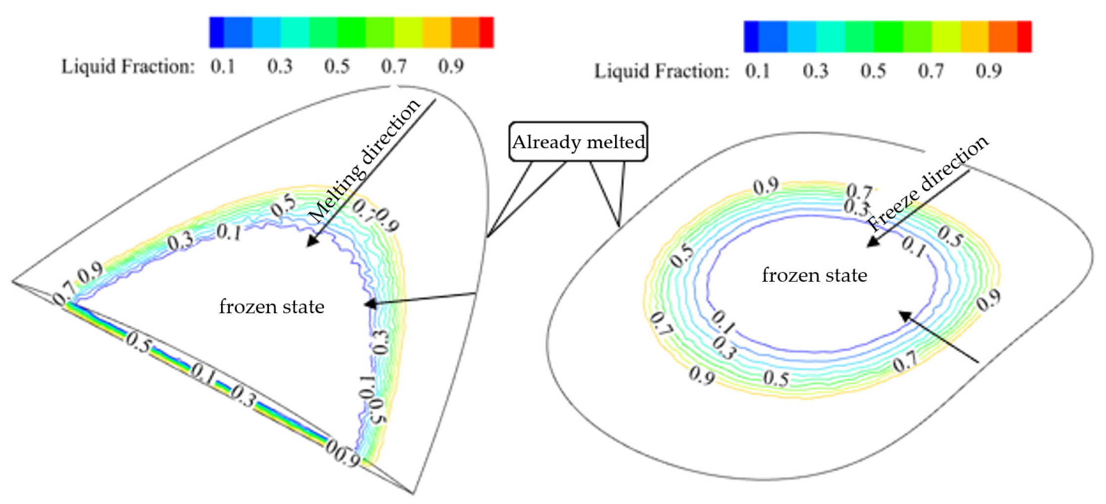
Under short-period temperature fluctuation conditions, when a positive temperature occurs in the lining structure, the ice formed starts to melt from the thinnest part, and then develops to the thickest part. This is the same as the freezing development process—that is, the ice that freezes first when cooling is also the first to melt when the temperature rises, as shown in Figure 10.
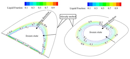
Figure 10.
The melting process of ice in the voids.
4.1.3. The Formation Mechanism of Frost-Heave Force within the Voids
For type I voids, the freeze/thaw cycle generally does not produce frost-heave force. Since the hollowed-out top surface is the initial support, we can considered the entire top surface a drainage channel. Under the condition of short-term temperature fluctuations, whether freezing or thawing, the groundwater supply and drainage channels will remain open, and frost heaving will essentially not occur.
For type II voids, the frost-heave force in the cavity will gradually increase under freeze/thaw cycles. Since the top surface of the hollow is a waterproof layer, the water accumulated within it is the seepage of groundwater flowing through the contact surface of the lining and the waterproof layer into the hollow cavity. The groundwater infiltration channels are located at the edge of the hollow cavity, where the thickness of the water body in the cavity is the greatest. The thin part is the first part to be frozen during the freezing process. Therefore, under the condition of short-term temperature fluctuations, when the temperature drops and freezing begins, the drainage channel freezes first, causing frost-heave force in the cavity; when the temperature rises and melting begins, the drainage channel melts first, and the cavity volume increases due to frost heaving caused by the accumulated water, and the new water body moves along the channel into the cavity. When freezing again, the excretion channel is also frozen first, causing frost-heave force in the cavity and causing the cavity volume to increase again. That is, under the condition of short-term temperature fluctuations, the water body in the cavity will undergo a cyclical process of frost heaving, melting, supplying water, and then further frost heaving. This causes the frost-heave force of the structure under the conditions of short-term temperature fluctuations to gradually increase, and lining cracks will occur, or even blockage, collapse, and other forms of damage.
4.2. Calculation and Analysis Model of Frost-Heave Force
After the formation mechanism and evolution process of frost-heave force are determined through numerical simulation, a more widely applicable frost-heave force calculation method should be proposed—that is, an analytical model that considers the calculation and analysis of frost-heave force under different drainage conditions.
4.2.1. Frost-Heave Force Calculation Model
At present, the frost-heave force of local water-retaining cavities is mostly calculated by referring to the theoretical definition of the tunnel’s overall freeze/thaw cycle. The frost-heave force calculated from the field tests ranged from 0.06 to 0.30 MPa [27], and the frost-heave force calculated analytically could reach more than 10 MPa [28]. The results of the two are quite different. There is currently no reliable basis for calculating the frost-heave force caused by the freezing of trapped water behind the tunnel lining.
Some scholars have conducted research on the frost-heave force of the local water storage space around tunnels [29]. Based on the cavity caused by the uneven early excavation surface of the tunnel, a frost-heave force calculation model considering the elastic resistance of the lining has been proposed. On this basis, Fan Lei [13] modified and re-derived the original local water frost-heave model by considering the elastic resistance of ice body deformation, using three series of springs to simulate the cavity deformation after the frost-heave force was generated. At the same time, the surrounding rock and the deformation coordination conditions for the simultaneous displacement of the lining structure were used to derive the frost-heave force calculation formula.
However, the above models all ignore the freezing process of water in the cavity and the supply and discharge conditions of groundwater during freezing. They assume that the water-retaining cavity is closed, which is different from the actual situation. Therefore, we propose a frost-heave force computational model that considers the excretion conditions of the empty cavity. Since tunnel vault voids often occur at the highest point of each mold lining near the end of the formwork, and the void cavities formed by concrete pouring are mostly circular wedge-shaped voids, the frost-heave force was calculated based on circular wedge-shaped voids, as shown in Figure 11.
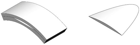
Figure 11.
Schematic diagram of void position and shape.
4.2.2. Frost-Heave Force of Circular Wedge-Shaped Voids without Considering Drainage Conditions
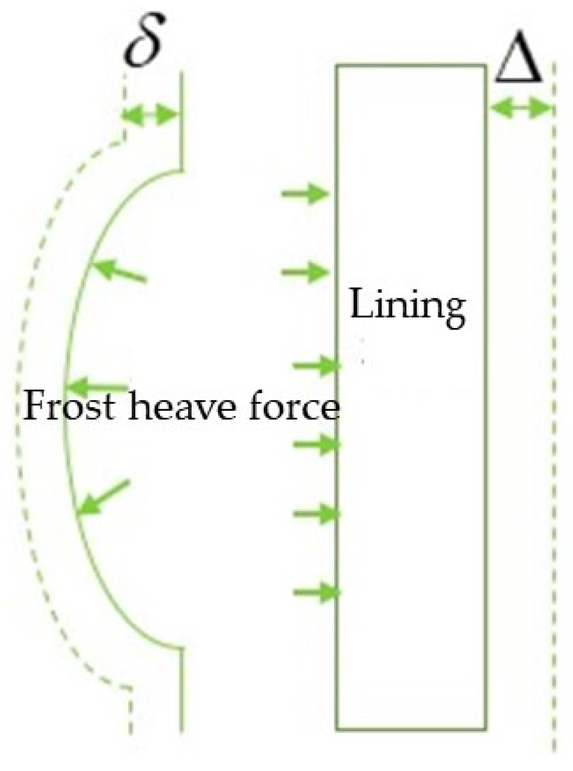
Assuming that the surrounding rock has the same properties and the gravity of the lining and the surrounding rock are not considered, the water storage space is formulated as a circular wedge shape. Referring to the calculation model in Figure 12, we must first calculate the frost-heave force caused by the void water without considering the drainage conditions.
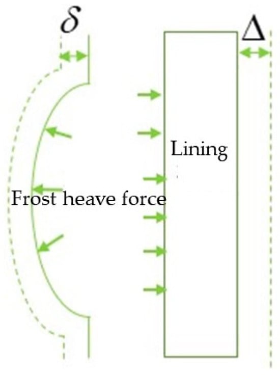
Figure 12.
Cross-sectional view of the void position.
According to the local deformation theory, under the action of frost-heave force, the deformation displacement value of the surrounding rock is
where is the elastic resistance coefficient of the surrounding rock (MPa/m), while is the elastic resistance coefficient of the ice (MPa/m).
The deformation displacement value of the lining is
where is the elastic resistance coefficient of the lining (MPa/m).
Since the frost-heave forces acting on the lining structure and the surrounding rock are the same,
Let
The calculation formula for the volume expansion of water in the cavity is
where Vi is the volume expansion of water in the cavity, α is the frost heave rate of ice, and Vv is the cavity volume or the volume of water in the cavity.
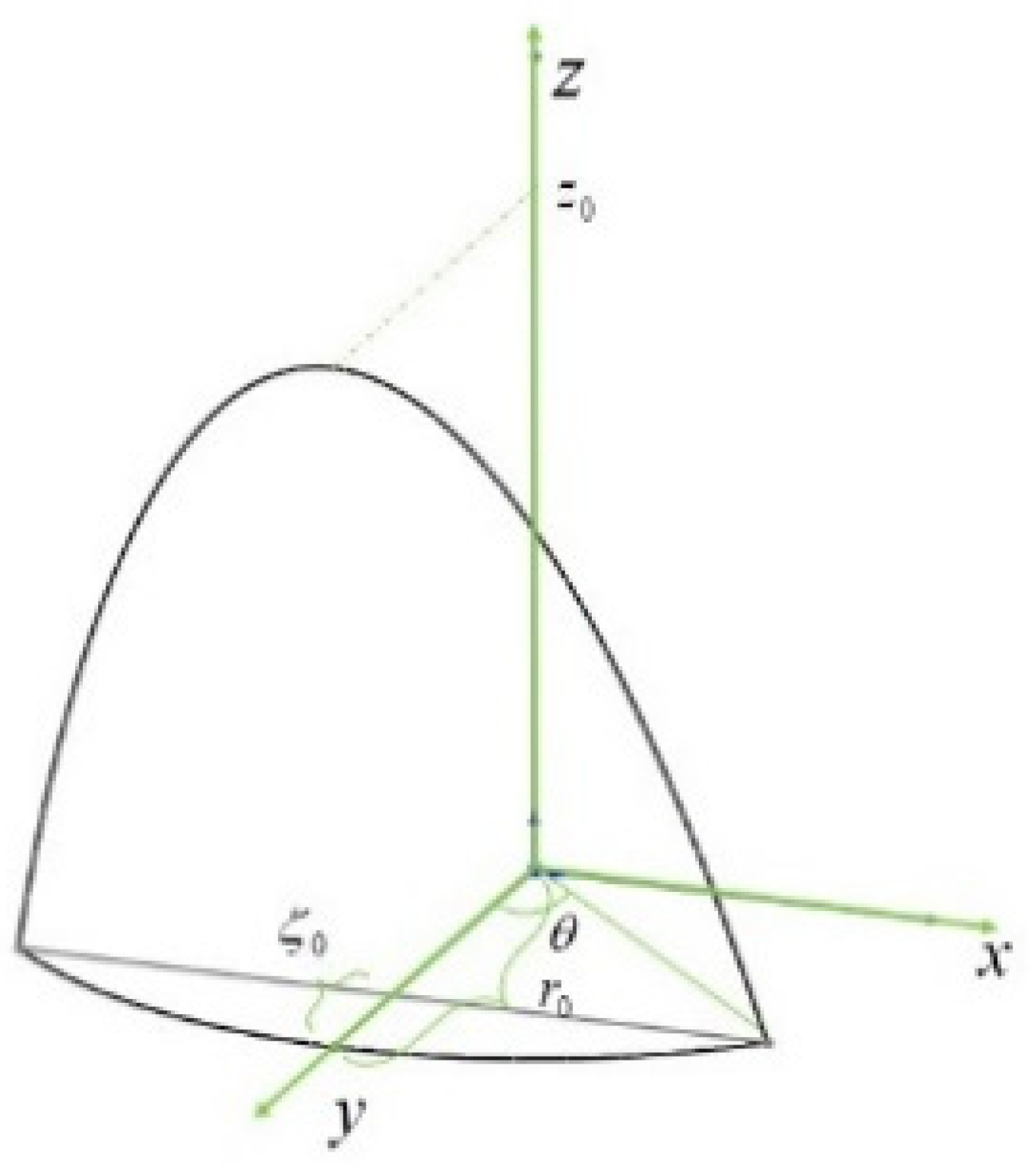
Now, assume that the outer radius of the lining is r0, the maximum height of the lining void is , the plane angle at the corresponding position is the void length z0, the center of the arc of the tunnel arch is the origin, and the longitudinal direction of the tunnel is the z-axis to establish a coordinate system. Its spatial model is as shown in Figure 13.

Figure 13.
Calculation model of frost-heave force in a circular wedge-shaped void.
The geometric equation of the cavity boundary curve is
Then, the volume of the cavity is
where
The cavity bottom area is
The cavity top surface area is
The amount of expansion caused by the freezing of water is equal to the volume deformation of the surrounding rock and lining, that is,
Combining Equations (8)–(14), the deformation value of the lining under the frost-heave force is
The frost-heave force on the lining structure is
Class IV surrounding rock conditions were selected for calculation; the outer radius r0 of the lining was taken to be 6.81 m, and the frost-heave rate α was taken to be 9%. The elastic resistance coefficient of the surrounding rocks was derived according to the “Railway Tunnel Design Code” [30]. As shown in Table 2, the elastic resistance coefficient of the lining was 75 MPa/m, and the elastic resistance coefficient of the ice was 50 MPa/m [31].
Table 2.
Elastic resistance coefficient of surrounding rocks at all levels.
4.2.3. Considering the Frost-Heave Force of Circular Wedge Hollowing under Drainage Conditions
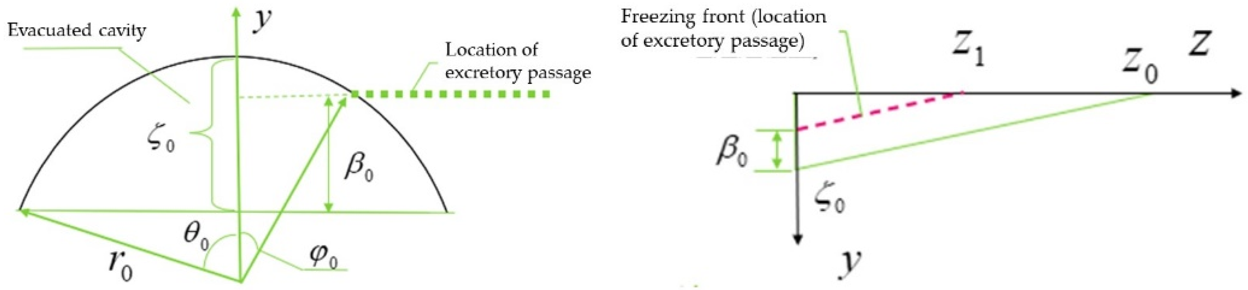
When there is a groundwater drainage channel in the cavity, part of the groundwater is extruded and discharged during the frost-heave process of the water body in the cavity, and then the drainage channel is frozen and the remaining water body freezes and heaves to generate frost-heave force. The volume of discharged water is mainly related to the location of the drainage channel and the shape of the cavity. The frost-heave force when there is a drainage channel was analyzed using a circular wedge-shaped cavity. As shown in Figure 14, the height of the emptying cavity was , and the drainage channel was located in the range of 0~. The water body froze from the bottom of the cavity. As the freezing front moved upward, the drainage channel was frozen, and the water body in the cavity could not be drained, resulting in the generation of frost-heave force.
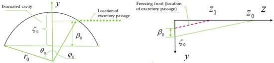
Figure 14.
Calculation model of frost-heave force in a circular wedge-shaped void considering the location of the excretion channel.
When selecting the instantaneous state, the heights of the freezing front and the excretion channel are the same, and when they are located at , the excretion channel freezes. When there is an excretion channel, the frost-heave force in the cavity is P−. Let
where is the discharge coefficient. When the water body in the cavity causes frost heaving, the ratio of the frost-heave force when there is water discharge to the frost-heave force when there is no discharge can be determined according to the relative position of the discharge channel and the void.
When the water body below the drainage channel is frozen, the volume of the water body that will generate frost-heave force during the subsequent freezing process is
At this time, the drainage channel has frozen. According to the calculation results of Equations (3)–(13), the frost-heave force generated by the remaining water body is
Comprehensive Equations (16), (17) and (22) show that
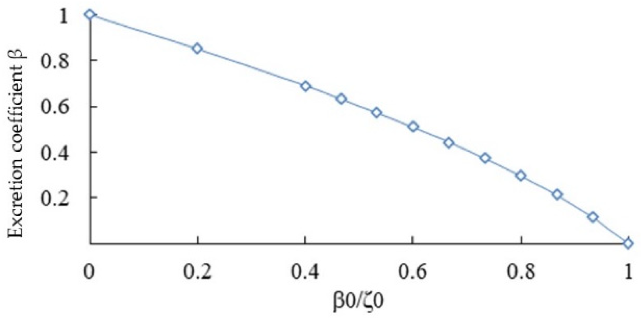
when = 0—that is, when the volume of water discharged during the freezing process is 0—the frost-heave force . When , the volume of discharged water is equal to the volume of water expanded when freezing, and the frost-heave force . The values of the excretion channel at different cavity heights can be obtained. During actual engineering use, the value can be determined by referring to the relative position of the excretion channel and the emptying cavity, as shown in Table 3. The graph of the relationship between the excretion coefficient and the excretion channel position is shown in Figure 15.
Table 3.
Elastic resistance coefficient of the surrounding rock at all levels.
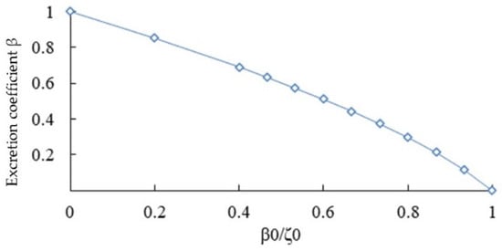
Figure 15.
Value curve of groundwater excretion coefficient.
It can be seen from Figure 15 that the magnitude of the frost-heave force is directly related to the location of the excretion channel. When the excretion channel is located at the top of the void, the water in the cavity is squeezed out during the freezing process, and there is essentially no frost-heave force in the cavity; when the excretion channel is located at the bottom edge of the void, the excretion channel is frozen first during the freezing process, and the void becomes a closed space, causing a large frost-heave force to be generated in the cavity. Both the discharge coefficient and the frost-heave force decrease as the distance between the discharge channel and the hollow bottom increases.
5. Discussion and Conclusions
In order to reveal the frost-heave mechanism of void water behind the lining of high-speed railway tunnels in cold areas, we first innovatively proposed the definition of two types of void water, classified the discharge conditions of these two types of void water during the freezing process, and experimentally analyzed the effects of the different discharge conditions on the frost-heave force. Then, based on the short-period temperature fluctuations and vault void morphological conditions, the circular wedge-shaped and flying-saucer-shaped void models were proposed, and numerical simulation was used to analyze the freezing process and characteristics of the two types of void water. Then, we comprehensively considered the relative position of the void and the drainage channel, introduced the drainage coefficient, and proposed an analytical model for calculating the frost-heave force in circular wedge-shaped voids, so as to understand the formation mechanism of frost heaving due to void accumulation.
Most existing research focuses on the effects of temperature, surrounding rock, and lining on frost-heave force. On this basis, this paper considers the influence of accumulated water discharge conditions, short-period temperature fluctuation conditions, and void formation on frost-heave force. In addition to discovering that the magnitude of the tunnel water frost-heave force is influenced by the elastic resistance coefficient of the surrounding rock, the elastic resistance coefficient of the lining, and the elastic resistance coefficient of the ice, we also found that blockage of the drainage channel leads to the generation of a large frost-heave force. The process of frost heaving, melting, water supply, and further frost heaving, caused by short-term temperature fluctuations, leads to the frost-heave force becoming greater and greater. The freezing and melting process of the accumulated water develops from the thinner area to the thicker area. The closer the drainage channel is to the relative position of the void bottom, the greater the drainage coefficient, the faster the drainage channel is frozen, and the greater the frost-heave force.
The above research helps to propose an early warning and prediction system based on temperature field fluctuations, water leakage in the tunnel, and tunnel voids. Due to the limitations of monitoring and measurement technology, it is impossible to accurately measure the frost-heave force and voids in the original tunnel. Therefore, it will be necessary to conduct further research on the relative positional relationship between voids and the excretory channel in the future. In addition, we can start from aspects such as the freezing situation of the drainage ditch, the degree of ice hanging on the lining surface, and the monitoring of void patterns to achieve early warning and prediction of macroscopic freezing damage for an entire tunnel.
Author Contributions
Conceptualization, Y.W.; Methodology, W.D.; Software, W.D.; Validation, Y.W.; Formal analysis, W.D.; Investigation, W.D. and Y.W.; Data curation, W.D.; Writing—original draft, W.D.; Writing—review & editing, W.D.; Visualization, K.H.; Supervision, Y.W.; Project administration, P.X.; Funding acquisition, P.X. All authors have read and agreed to the published version of the manuscript.
Funding
This research was funded by [National Key Research and Development Program of China] grant number [2022YFB2603301] and [National Natural Science Foundation of China] grant number [51478473].
Institutional Review Board Statement
Not applicable.
Informed Consent Statement
Not applicable.
Data Availability Statement
The data presented in this study are available on request from the corresponding author. The data are not publicly available due to privacy.
Conflicts of Interest
The authors declare no conflict of interest.
References
- Pan, H.; Li, H.; Zhang, T.; Laghari, A.; Zhang, Z.; Yuan, Y.; Qian, B. A Portable Renewable Wind Energy Harvesting System Integrated S-rotor and H-rotor for Self-Powered Applications in High-Speed Railway Tunnels. Energy Convers. Manag. 2019, 196, 56–68. [Google Scholar] [CrossRef]
- Li, Y.; Chen, S. Analytical Solution of Frost Heave Force for Noncircular Tunnels in Cold Region. Chin. J. Theor. Appl. Mech. 2019, 196, 56–68. [Google Scholar]
- Lai, J.; Liu, C.; Gong, C. Temperature Field Analysis of Electric Tracing for Pavement of Tunnel Portal in Cold-region by FEM. Procedia Eng. 2011, 15, 5468–5472. [Google Scholar] [CrossRef]
- Lai, J.; Qiu, J.; Fan, H.; Chen, J.; Xie, Y. Freeze-proof method and test verification of a cold region tunnel employing electric heat tracing. Tunn. Undergr. Space Technol. Inc. Trenchless Technol. Res. 2016, 60, 56–65. [Google Scholar] [CrossRef]
- Zhang, S.; Bao, T.; YOO, C.; Liu, C.; Li, P. Design, Test, and Engineering Application of a Composite Waterproof and Drainge System in Tunnels. China J. Highw. Transp. 2021, 34, 198–208. [Google Scholar]
- Zhao, T.; Dai, C. Analysis of Tunnel Deicing Technology based on Cold Region. Heilongjiang Sci. Technol. Water Conserv. 2021, 49, 1–5+83. [Google Scholar]
- Chen, Z.; Xiao, B.; Wang, Y.; Zhang, H.; Lv, X. Inhibition ofRunback Ice Via Superhydrophbic Electrothermal Film. Aeronaut. Sci. Technol. 2021, 32, 75–80. [Google Scholar]
- Yang, X.; Wu, X.; Zhou, D.; Min, T. Research on Design Method of Ceramic Piezoelectric Graphene Deicing System. Technol. Innov. Appl. 2022, 12, 108–109+112. [Google Scholar]
- Li, H.; Xue, C.; Jia, S. Preparation and anti-icing properties of carbon black/PDMS photothermal superhydrophobic coating. Fine Chem. 2021, 38, 934–940. [Google Scholar]
- Wu, H.B. A Research on Frost Heaveforce and Temperature Field Inside Long Road Tunnels in Cold Are. Master’s Thesis, Southwest Jiaotong University, Chengdu, China, 2015. [Google Scholar]
- Zhang, Y.; Fan, S.; Yang, D.; Zhou, F. Investigation About Variation Law of Frost Heave Force of Seasonal Cold Region Tunnels: A Case Study. Front. Earth Sci. 2022, 9, 806843. [Google Scholar] [CrossRef]
- Zhang, M.; Liu, H.; Yang, L.; Li, X.; Wang, Z. Experimental study on horizontal frost heave force on open-cut tunnels in seasonal frozen regions. Front. Earth Sci. 2023, 10, 1022058. [Google Scholar]
- Fan, L.; Zeng, Y.; He, C.; Cheng, X. Magnitude and Distribution of Frost Heave Force for Cold Region Strong Rock Tunnels. China Railw. Sci. 2007, 28, 44–49. [Google Scholar]
- Zhang, J.; Zhang, X.; Fu, H.; Wu, Y.; Huang, Z. An Analytical Solution for the Frost Heaving Force considering the Freeze-Thaw Damage and Transversely Isotropic Characteristics of the Surrounding Rock in Cold-Region Tunnels. Adv. Civ. Eng. 2020, 2020, 6654778. [Google Scholar] [CrossRef]
- Cui, G.; Ma, J.; Wang, X.; Wang, D. Model and calculation method of frost heaving stress of stagnant water of tunnel in seasonally frozen area. Geomat. Nat. Hazards Risk 2021, 12, 1669–1687. [Google Scholar] [CrossRef]
- Yang, J.; Gong, L. Research on Remediation Techniques for Insufficient Lining Thickness of Voided Arch Roof in Operational Tunnels. Highway 2022, 67, 321–329. [Google Scholar]
- Du, P. Discussion on Causes, Remediation and Precautionary Measures for Unseen Voids in the Secondary Linings of High-speed Railway Tunnel. Railw. Constr. Technol. 2019, 306, 101–104. [Google Scholar]
- Zhou, X.; Ren, X.; Ye, X.; Tao, L.; Zeng, Y.; Liu, X. Temperature field and anti-freezing system for cold-region tunnels through rock with high geotemperatures. Tunn. Undergr. Space Technol. 2021, 111, 103843. [Google Scholar] [CrossRef]
- Ding, Z.; Wen, J.; Ji, X.; Ren, Z.; Zhang, S. Experimental Investigation of the Mechanical Behavior of NC Linings in consideration of Voids and Lining Thinning. Adv. Civ. Eng. 2020, 2020, 8876785. [Google Scholar] [CrossRef]
- Liu, H.; Yuan, X.; Xie, T. A damage model for frost heaving pressure in circular rock tunnel under freezing-thawing cycles. Tunn. Undergr. Space Technol. 2019, 83, 401–408. [Google Scholar] [CrossRef]
- Gao, Y.; Jiang, Y.; Li, B. Estimation of effect of voids on frequency response of mountain tunnel lining based on microtremor method. Tunn. Undergr. Space Technol. 2014, 42, 184–194. [Google Scholar] [CrossRef]
- Wu, Y.; Li, W.; Fu, H.; Liu, M. Numerical simulation of freeze-thaw in short period of secondary lining at tunnel transition section in seasonal frozen area. Chin. J. Geotech. Eng. 2017, 39, 1930–1935. [Google Scholar]
- Tan, X.; Chen, W.; Yang, D.; Dai, Y.; Wu, G.; Yang, J.; Yu, H.; Tian, H.; Zhao, W. Study on the influence of airflow on the temperature of the surrounding rock in a cold region tunnel and its application to insulation layer design. Appl. Therm. Eng. 2014, 67, 320–334. [Google Scholar] [CrossRef]
- Xu, P.; Wu, Y.; Wang, Z.; Huang, L. Distribution Laws of Freeze-Thaw Cycles and Unsaturated Concrete Experiments in Cold-Region Tunnels. Cold Reg. Sci. Technol. 2020, 172, 102981–102985. [Google Scholar]
- Wu, Y.; Xu, P.; Huang, L.; Cai, Z.; Hu, K. Progressive deterioration of tunnel lining in seasonal freezing zone and its engineering influence. J. Chang. Univ. Nat. Sci. Ed. 2021, 41, 63–72. [Google Scholar]
- Xu, P.; Wu, Y.; Huang, L.; Zhang, K. Study on the Progressive Deterioration of Tunnel Lining Structures in Cold Regions Experiencing Freeze–Thaw Cycles. Appl. Sci. 2021, 11, 5903. [Google Scholar] [CrossRef]
- Feng, Q.; Jiang, B. Analytical Calculation on Temperature Field of Tunnels in Cold Region by Laplace Integral Transform. J. Min. Saf. Eng. 2012, 29, 391–395. [Google Scholar]
- Feng, Q.; Jiang, B. Analytical method for insulation layer thickness of highway tunnels with multilayer dielectric in cold regions. Chin. J. Geotech. Eng. 2014, 36, 1879–1887. [Google Scholar]
- Wang, J.; Hu, Y. A Discussion on Frost Heave Force Acting on Tunnel Lining. J. Railw. Eng. Soc. 2004, 87–93. [Google Scholar]
- TB10003-2016; Code for Design of Railway Tunnel. State Railway Administration: Beijing, China, 2016.
- Zhang, Z.; Wang, L. Discussion on the design of tunnels in high elevation and bitter cold region. Mod. Tunn. Technol. 2004, 41, 6. [Google Scholar]
Disclaimer/Publisher’s Note: The statements, opinions and data contained in all publications are solely those of the individual author(s) and contributor(s) and not of MDPI and/or the editor(s). MDPI and/or the editor(s) disclaim responsibility for any injury to people or property resulting from any ideas, methods, instructions or products referred to in the content. |
© 2024 by the authors. Licensee MDPI, Basel, Switzerland. This article is an open access article distributed under the terms and conditions of the Creative Commons Attribution (CC BY) license (https://creativecommons.org/licenses/by/4.0/).