Article

Zinc Plating on Inkjet-Printed Ti3C2Tx MXene: Effect of Electrolyte and PEG Additive

Dipartimento di Chimica, Materiali e Ingegneria Chimica “Giulio Natta”, Politecnico di Milano, Via Mancinelli, 7, 20131 Milano, Italy
*
Author to whom correspondence should be addressed.
Appl. Sci. 2024, 14(2), 682; https://doi.org/10.3390/app14020682
Submission received: 12 December 2023 / Revised: 9 January 2024 / Accepted: 10 January 2024 / Published: 13 January 2024
(This article belongs to the Special Issue Advances in Graphene and Graphene Related Materials)

Abstract

:
Zinc-ion batteries (ZIBs) are currently being studied as an alternative to lithium-ion batteries (LIBs). The nucleation and growth of the zinc deposition mechanism is a critical field of research in ZIBs, as it directly affects the battery efficiency and lifespan. It is of paramount importance in mitigating the formation of porous, dendritic Zn structures that may cause cell inefficiency and, eventually, short-circuiting failures. Interfacial engineering plays a key role in providing reversible plating and stripping of metallic Zn in ZIBs through the proper regulation of the electrode–electrolyte interface. In this work, we investigated the behavior and characteristics of Zn plating on inkjet-printed Ti3C2Tx MXene-coated substrates according to the different electrolyte compositions. Specifically, ZnCl2 and ZnSO4 solutions were employed, evaluating the effect of a relatively low-molecular-weight polyethylene glycol (PEG400) addition to the electrolyte as additive. Electrochemical analyses demonstrated higher deposition kinetics in chloride-based electrolytes rather than sulfate ones, resulting in lower nucleation overpotentials. However, the morphology and microstructure of the plated Zn, investigated via scanning electron microscopy (SEM) and X-ray diffraction (XRD), revealed that the electrolytic solution played a predominant role in the Zn crystallite formation rather than the Ti3C2Tx MXene coating. Specifically, the preferential Zn [002] orientation could be favored when using additive-free ZnSO4 solution, and a PEG addition was found to be an efficient texturing agent only in ZnCl2 solution.

1. Introduction

Environmentally responsible, reliable, and long-lasting energy power sources are nowadays highly demanded and are at the core of research and industry attention. In this frame, electrochemical energy storage systems represent valid solutions as they reliably store energy in case of necessity, being able to compensate for the limitations of renewable energies linked to intermittency and instability. Lithium-ion batteries (LIBs) are nowadays the dominant technology in electric vehicles and portable electronics applications because of their high power and energy densities [1,2]. However, LIB alternatives are currently under study because of the limited availability of lithium and the general high costs associated with the production of these devices. Moreover, safety concerns associated with the use of organic, poisonous electrolytes pose severe limitations on the large-scale adoption of LIBs [3,4,5]. Among such alternatives, zinc-ion batteries (ZIBs) have attracted interest because of their high element earth-abundance, high Zn specific capacity (820 mAh g−1) and lower estimated costs (US $65 kW h−1 for ZIBs vs. over US $300 kW h−1 for LIBs) [6]. In particular, the low Zn redox potential, i.e., −0.763 V vs. SHE, allows ZIBs with aqueous electrolyte chemistry that are intrinsically safer with respect to the organic one used in LIBs [7,8]. However, ZIBs are usually plagued by zinc mossy growth, resulting in poor coulombic efficiency of charge and discharge cycles as a result of the poor electrification of the loosely bounded Zn mossy structures, eventually leading to battery failures [9,10,11,12]. Such phenomenon, which is worsened in alkaline electrolytes, is usually associated with a low surface potential and/or uneven Zn ion diffusion toward the anode electrode surface. In this case, Zn ions are preferentially reduced on Zn protuberances rather than on the flat Zn surface, according to the well-known “tip effect” [13,14,15]. Considering this, researchers are applying considerable effort toward finding solutions able to erase or mitigate Zn dendritic growth, favoring a homogeneous Zn-plating process. These include the development of novel structural designs of Zn anodes, electrode–electrolyte interface optimization by the formation of in-situ or ex-situ interfacial coatings and protective layers, and electrolyte additives as well as functionalized separators [11,16,17,18].
Organic and inorganic electrolyte additives can efficiently inhibit Zn dendrite formation, favoring the growth of a smooth and bright surface, usually achieved thanks to the preferential [002] orientation of Zn crystals [19,20]. More specifically, such additives are able to create a blocking barrier for the reactants, i.e., zincates, at the electrode surface, favoring a more even deposition and suppressing preferential Zn growth on dendrites [21]. In particular, among the various organic additives, polyethylene glycols (PEGs) were extensively investigated, whose inhibiting effects derive from the oxygen radicals used for adsorption [22], in which it was shown how their addition to an electrolyte can influence the morphology of the zinc deposit. Specifically, grain sizes were reduced, producing smooth deposits [22,23].
In terms of interfacial engineering, “zincophilic” coatings such as Ti3C2Tx MXene (MX) were recently demonstrated to be particularly effective as an interfacial layer to achieve smooth deposition on metal anodes such as Li, Na, K, and Zn [24,25,26,27]. Ti3C2Tx MXene can unlock fast electrochemical kinetics in the plating/stripping process due to its high electronic conductivity and rapid Zn-ion diffusion. In fact, Ti3C2Tx MXene has also been employed in Zn-ion supercapacitors owing to their outstanding Zn-ion adsorption capability [28,29]. Moreover, their hydrophilic functional groups improve electrode wettability [30,31,32,33] with electrolytes, resulting in lower interface impedance and more uniform ion flux [34,35]. In particular, the HCP crystal structure of Ti3C2 MXene was recently demonstrated to be particularly “zincophilic” [24,27,34,36,37,38,39] because of the synergistic effect of a matching lattice degree between Ti3C2Tx and Zn and because the presence of halogenated terminations on the Ti3C2Tx surface favors the production of a coherent heterogeneous MX/Zn interface, which influences and regulates the subsequent homogeneous Zn growth [35,40,41].
In this work, we investigated the effect on the Zn nucleation and growth of both a thin, zincophilic Ti3C2Tx substrate and a PEG400 additive in Zn aqueous electrolytes. Inkjet printing was employed as a suitable technique to quickly achieve Ti3C2Tx uniform coatings on SS316 substrates. The mechanism of Zn plating in ZnCl2 and ZnSO4 solutions with and without PEG400 was investigated by electrochemical potentiodynamic techniques as well as microstructural and morphological analyses in order to assess the best condition for optimal Zn growth. It was found that the quality of the Zn layer grown on the Ti3C2Tx layer, in terms of microstructure, strictly depends on the kind of electrolyte used, and PEG400 was demonstrated to effectively improve the homogeneity of Zn plating only in ZnCl2 electrolytes.
In this work, inkjet printing was employed as a non-conventional technique, rarely reported in the literature, for the surface modification of battery electrodes. A printable Ti3C2Tx MXene ink was formulated and jetted onto SS316 substrates, providing uniform Ti3C2Tx coatings. We focused our investigations on the effect of the thin Ti3C2Tx coating and the electrolyte composition with and without PEG400 additive on the Zn nucleation and growth behavior. Electrochemical potentiodynamic techniques as well as microstructural and morphological analyses assessed the best conditions for optimal Zn growth. It was found that, in terms of microstructure, the quality of Zn grown on the printed Ti3C2Tx strictly depends on the kind of electrolyte used, and PEG400 was demonstrated to effectively improve the homogeneity of Zn plating only in ZnCl2 electrolytes.

2. Materials and Methods

Ti3C2Tx MXene Synthesis—Ti3C2Tx MXene was synthesized through the mixed-acid approach [31,42]. A mass of 10 g of Ti3AlC2 MAX phase (Luoyang Advanced Material Co., Ltd., Luoyang, China) was added to an etchant solution composed of 30 mL of HF, 120 mL of HCl, and 60 mL of H2O. The solution was left to stir at 300 rpm for 24 h at 35 °C. The obtained multilayered Ti3C2Tx was washed multiple times by centrifugation at 3500 rpm for 5 min until a pH of 5–6 was obtained. A final delamination step of the multilayered Ti3C2Tx phase was performed, adding 2 g of Ti3C2Tx to a solution of 40 mL of water and 2 g of LiCl. The solution was placed in a vial and agitated with a mixer homogenizer for 30 min at 2400 rpm. Then the solution was subjected to this series of centrifuges: 3 cycles at 3500 rpm for 10 min, 1 cycle at 5000 rpm for 1 h, and 1 cycle at 8000 rpm for 20 min, discarding the transparent supernatant and redispersing the sediment between each cycle.
Ti3C2Tx MXene Ink Preparation and Printing—The Ti3C2Tx ink preparation was re-adapted from a previously reported protocol [43] and prepared according to the following procedure: 40 mL of the delaminated suspension were placed in a beaker, and 0.1 g of Na-asc was added. The solution was stirred for 10 min, transferred to a bath sonicator (20 W/L) for 30 min, and then to a probe sonicator (2 s on, 2 s off, 180 W, 30 min of total time). The Ti3C2Tx dispersion was finally centrifuged for 10 min at 1000 rpm, and ultimately, 3 mM of LDS (lithium dodecyl sulfate) were added to obtain the final ink. A flat-bed thermal inkjet printer (Breva, IJet2L, San Vittore Olona, Italy) equipped with a Ti3C2Tx ink-filled HP45 cartridge was employed for inkjet printing operations. The native printer resolution was 600 dpi. Typically, the substrates were placed on the flat bed and heated at 40 °C, and 20 layers of the Ti3C2Tx ink were consecutively overprinted to achieve a consistent MXene load. After printing, the Ti3C2Tx-coated samples were dried in an oven at 70 °C for 1 h.
Characterization—electrolytes were prepared by dissolving 2M ZnCl2 or 2M ZnSO4 in water solution with and without 10% wt. PEG400 (Sigma-Aldrich, Saint Louis, MO, USA). Electrolyte conductivity was investigated through a portable multi-range conductometer (Hanna Instruments, Villafranca Padovana, Italy). For electrochemical analyses, 20 layers of the Ti3C2Tx ink were printed on an SS316 disk of 15 mm diameter. Cyclic voltammetries were performed through a Squidstat Plus potentiostat (Admiral Instruments, Tempe, AZ, USA) using a pure Zn wire (diameter 1.5 mm) as the counter electrode and Ag/AgCl (3M KCl) as the reference electrode. All the electrochemical tests were performed without stirring the solution. Tafel plots were built on the cathodic scan only of the 2 mV s−1 cyclic voltammetries. Electrochemical impedance spectroscopy (EIS) measurements were performed with the same three-electrode configuration described above using a Biologic VSP-300 potentiostat equipped with an EIS channel in the frequency range 100 kHz–100 mHz using 10 mV as pulse amplitude at open circuit potential. All measurements were performed at room temperature. Hull cell tests were carried out using a small 3D-printed (polypropylene) trapezoidal-shape Hull cell (33 mL volume, long side of 65 mm, short side of 25 mm, height of 32 mm). A 20-printed layer of Ti3C2Tx on a steel plate (34 mm × 50 mm × 1 mm) and a Pt plate (32 mm × 32 mm × 2 mm) were used as the cathode and anode panels, respectively, fixing the current at 100 mA for 20 min.
Zn deposit morphology was investigated through a scanning electron microscope (SEM, Zeiss EVO 50 EP) equipped with an EDX detector (x-sight detector, Oxford instruments, Abingdon, UK), and microstructure was analyzed with an X-ray diffraction (XRD) microscope (model PW1830, Kα1Cu = 1.54058 Å, Philips, Eindhoven, The Netherland). The crystallite size (D) of plated Zn crystals at 5 mA cm−2 was calculated by means of the Scherrer equation, D = (0.94 λ)/(β cosθ), where λ is the X-ray wavelength (λ = 1.54058 Å), β is the line broadening at half the maximum intensity (FWHM), and θ is the Bragg angle of the [002] peak. Dynamic light scattering (DLS) was used to investigate the Ti3C2 MXene nanosheet size distribution in the aqueous ink (Zeta sizer Nano, Malvern, UK) at a scattering angle of 173° (backscatter).

3. Results

Ti3C2Tx MXenes were successfully obtained by the well-known procedure of mixed acid (HF-HCl) etching and subsequent delamination in LiCl solution. Successful etching was confirmed by SEM analyses (Figure S1a), which clearly showed the “open-book” morphology of the particles as a result of the Al selective etching [33]. EDX analyses (Figure S1b,c) also reported a very low average Al-to-Ti atomic ratio (0.041), confirming successful Al removal. On the other hand, XRD (Figure S2) assessed the successful delamination into individual Ti3C2Tx MXenes sheets because of the left shift of the intense [002] peak to a very low diffraction angle (6°) as well as the progressive disappearance of the higher-order peaks [44,45]. According to the average hydrodynamic diameter measured by DLS analysis (Figure S3), the average lateral size of the 2D MXene sheets was estimated to be 302 nm [41].
Inkjet printing is a well-known technique capable of quickly producing thin coatings on any substrate by the jetting of small droplets of a colloidal nanoparticle suspension through the nozzles of the printhead. Despite its wide industrial employment and suitability for the interfacial engineering regulation of the electrodes, poor attention was devoted to inkjet printing, and the usual slurry electrode coating is usually preferred. The Ti3C2Tx MXene ink we formulated was easily printable, and Ti3C2Tx-coated electrodes could be quickly produced. The consistency and repeatability of the printing process were checked by weighting the samples. Figure S4 shows that even after more than 1 month of ink storage, the printed Ti3C2Tx mass was highly reproducible, meaning that the as-prepared ink was stable and no agglomeration or nozzle clogging occurred. Samples were prepared by printing 20 consecutive overlayers, resulting in a Ti3C2Tx mass load of 0.452 mg cm−2. The EDX mapping (Figure S5) of the bright bluish Ti3C2Tx-coated electrodes revealed a very smooth surface and uniform elemental distribution. The thickness of the dried Ti3C2Tx 20-layer coating was estimated to be ~2 µm by the SEM analysis of the cross-section (Figure S6).
The CVs of the Ti3C2Tx-coated electrodes in chloride or sulfate-based zinc electrolytes, with and without 10% wt. PEG400 as additive, are reported in Figure 1a. At a low scan rate (2 mV s−1), the typical Zn plating and stripping behavior was clearly visible for each of the investigated electrolytes, with a sloped cathodic curve and a broad anodic peak corresponding to the Zn reduction (plating) and oxidation (stripping), respectively. As reported in Table 1, in terms of charges and current density peaks, the chloride-based electrolyte generally resulted in the highest values when compared to the sulfate-based one.
For instance, the charge related to Zn plating (Qplat) in the PEG-free 2M ZnCl2 electrolyte was 3.34 higher than the PEG-free 2M ZnSO4. Evidently, PEG addition induced a reduction of the electrochemical activity, suggesting that the kinetics of the Zn plating were partially hindered by the PEG400 macromolecules. In fact, when the Qplat is considered, a 10% wt. PEG400 addition resulted in a 36.8% reduction in ZnCl2-based electrolytes and 55.4% in the ZnSO4-based one. The higher extent of the zinc ion reduction and consecutive zinc metal oxidation, with respect to the electrolyte composition, can be related to faster nucleation and growth rate. In particular, the nucleation process strongly depends on the nucleation overpotential (η), as defined in the following equation [46,47]:
η = η o n s e t η c r o s s
where η c r o s s is the crossover potential corresponding to the equilibrium growth regime, and η o n s e t is the onset potential of the reduction process [46]. Both η o n s e t and   η c r o s s were extracted by cyclic voltammetries, as shown in Figure 1b. Values of the nucleation overpotential are reported in Table 1, and η coherently increased when shifting from ZnCl2 to ZnSO4-based electrolytes as well as when adding PEG400. More specifically, the η values increased to different extents when PEG400 was added to the ZnCl2 or ZnSO4 solutions. In 2M ZnCl2 + 10 wt.% PEG400, the overpotential value increased just slightly from 62 mV to 71 mV, while in the case of 2M ZnSO4 + 10 wt.% PEG400, it consistently rose from 80 mV to 121 mV. This effect can be explained considering the different Zn-ion oligomer formations with PEG400 molecules. In fact, previous work demonstrated that the Zn2+-PEG oligomer strength strictly depends on the counter-ions because of the different Zn ion solvation environments in zinc sulfate solutions with respect to zinc halide (Cl, I, Br) ones [48]. Contrary to zinc halide electrolytes, in ZnSO4 solution, zinc ions are strongly shielded by H2O molecules that firmly bind to PEG through H-bondings, resulting in stronger Zn-ion oligomer formation and, as a consequence, an overpotential increase. The nucleation overpotential is known to have an impact on the Zn nuclei radius, which is given by the following equation [14,46]:
r n = 2 γ V m F η    
where γ is the surface energy of the interface between Zn and electrolyte, Vm is the molar volume of Zn, and F is the Faraday constant. As a consequence, a higher η should result in a higher density of smaller nuclei. That was demonstrated to be a favorable condition for dendrite-free growth of Zn. Moreover, the variation of η suggested that the nucleation process on the Ti3C2Tx surface was strictly affected by the electrolyte composition. It is noteworthy to recall that nucleation and growth processes are affected both by the rate of charge transfer and mass transport, and the substrate mostly plays a role in the nucleation through the surface energy regulation in Equation (2). Mass transport is instead ruled by the ionic conductivity of the electrolyte, and, as reported in Table 2, the ionic conductivity decreased 2-fold from 2M ZnCl2 to 2M ZnSO4, and it further dropped when PEG400 was included in the electrolyte. The ionic conductivity reduction in PEG400 was reasonable considering the increase in solution viscosity as well as the complexing ability of PEG macromolecules with Zn2+, forming bulky zinc-ion oligomers [48].
Considering the cyclic voltammetries in a wide scan-rate range (2–100 mV s−1, Figure S7), it is evident that the mass transport limitation regime strictly depended on the electrolyte composition and its ionic conductivity. In fact, at all scan rates, the reduction curves in chloride-based solutions remained sloped, as is typical of a charge-transfer kinetically controlled process. Contrarily, in zinc sulfate-based electrolytes, mass transfer limitations to the reduction process appeared, starting from 25 mV s−1 and 10 mV s−1 for the ZnSO4 electrolytes with and without PEG, respectively, as the transition from a sloped branch to a well-defined cathodic peak. Comparing the ionic conductivity and nucleation overpotentials, a coherent trend could be pointed out. The exchange current density (i0) values reported in Table 1, obtained by the fitting of linear branches in Tafel plots (Figure 1c), showed that the highest i0 was reported for the ZnCl2 electrolyte, representative of a faster intrinsic rate of the redox reaction at the equilibrium. In PEG-free zinc sulfate electrolyte, the i0 decreased to 2.95 mA cm−2 and i0 values lowered by the addition of PEG400, both in ZnCl2 and ZnSO4 electrolytes, consistent with the hypothesis of the Zn-oligomer adsorption, or more generally speaking of the PEG400 macromolecules, which can increase the de-solvation energy of zinc ions [48]. Nyquist plots (Figure 1d) clearly showed a right shift on the Z’ axis with respect to the electrolyte composition as well as an increase in charge transfer resistance. In particular, the electrolyte ionic conductivity was related to the R1 value, while the charge transfer resistance was the diameter of the semicircle and was noted as R2. Both R1 and R2 values are reported in Table 3.
It can be easily demonstrated that R1 is representative of the ohmic resistance of the electrolyte since the ratio of ionic conductivities with respect to the 2M ZnCl2 solution corresponded to the ratio of R1 values with respect to the one of 2M ZnCl2 (   σ σ Z n C l 2   =   R 1 R 1 ,   Z n C l 2   ). On the other hand, the charge-transfer resistance (R2) depends on the energy of de-solvation of ions from the surface, and it is directly related to the rate of the redox reaction and nucleation overpotential, according to the equation (derived by the Butler–Volmer equation) [14,49]:
i = i 0 z F R T η ,       R c t = R T z F i 0      
where η is the applied overpotential, T is the temperature, R is the gas constant (8.314 J mol−1 K−1), F is the Faraday constant (96,485 A s mol−1), z is the electron moles, and i0 is the exchange current density. The R2, Eq.3, calculated from Equation (3), and the i0 values reported in Table 1 were in good agreement with the R2 obtained by the fitting of Nyquist plots. In summary, both R2 and i0 reflected the fact that in chloride-based solutions, the fast rate of charge transfer, i.e., the fast rate of reversible Zn2+ de-solvation and adsorption to the Ti3C2Tx surface, resulted in the lowest nucleation overpotential values, different from the zinc sulfate electrolytes. As a consequence, it was possible that the anions (Cl or SO42−) were adsorbed differently on the Ti3C2Tx surface, affecting the charge transfer resistance, as already demonstrated for other species as saccharin anions [47]. Reasonably, PEG400 always increased the R2 for the aforementioned mechanisms [48,50,51].
The electrochemical results were correlated to the morphological and microstructural properties by SEM and XRD analyses on samples prepared by Hull cell. Hull cell is a useful tool widely employed in the galvanic plating industry to reproduce the cathodic plating process. The trapezoidal shape of the Hull cell was designed to allow the investigation of the electroplating characteristic over a wide range of current densities in a single experiment. A picture of the employed Hull cell setup is reported in Figure S8. Figure 2 reports the SEM images of the Zn deposits plated on the Ti3C2Tx-coated electrodes according to the specific electrolytes and local current density. Compared to the pristine Ti3C2Tx-coated surface (Figure S9), Zn crystals always appeared at both low (1 mA cm−2) and higher (5 mA cm−2) current densities after 20 min of plating. PEG-free ZnCl2 solutions (Figure 2a–c) produced a compact Zn deposition without a well-defined surface texture and irregular crystal morphology. Moreover, Zn crystal density was evidently higher in the case of 5 mA cm−2, as a result of the higher current density, which produced a superior nuclei density. PEG-free ZnSO4 electrolyte (Figure 2g,h) clearly improved the preferential orientation of the zinc HCP crystals, resulting in a more defined morphology of hexagonal-like Zn particles, particularly evident at 5 mA cm−2 (Figure 2i). Individual Zn crystals seemed to grow vertically from the Ti3C2Tx substrate rather than forming a very compact and dense layer. A few perfectly hexagonal Zn crystals were evidently growing from the surface of the MXene coating (Figure 2i), with an approximate size of 100 µm. Comparing the PEG-free electrolytes, the electrolyte itself (specifically the counter-ions Cl or SO42−) seemed to play a major role in the growth of textured Zn rather than the Ti3C2Tx layer itself. In fact, the Ti3C2Tx coating should promote epitaxial-like growth of the plated Zn layer because of the good matching between the two crystal lattices [40]. However, SEM analyses supported the electrochemical results, suggesting that ion mobility and/or a different anion adsorption at the electrolyte/Ti3C2Tx interface mostly ruled the surface overpotential and the resulting Zn electro crystallization. Increasing surface overpotential was, in fact, demonstrated to be the key feature enabling the smooth growth of compact Zn. Specifically, higher surface overpotential (or higher current density) produces more spatially uniform current distribution and faster growth rate of the [002] planes with respect to the [001] one [14,46,52,53,54]. Actually, the higher nucleation overpotential and charge-transfer resistance in ZnSO4 electrolytes, contrary to the fast deposition kinetic in ZnCl2 resulting from the electrochemical analyses, were coherent with this view and the actual plated-Zn morphology. A 10% wt. PEG400 addition to the electrolyte greatly affected the plated-Zn morphology but, in the opposite way, when added to the ZnCl2 or ZnSO4 solutions. In ZnCl2 + 10% wt. PEG400, the coating homogeneity was macroscopically greatly improved compared to the PEG-free chloride-based electrolyte. In fact, polyethylene glycols are known to act as a leveling agent; PEG macromolecules adsorbed at the Ti3C2Tx surface hinder the lateral 2D diffusion of zinc ions and the restricted surface migration, resulting in a higher density of small nuclei and more homogeneous Zn. However, SEM images (Figure 2d–f) didn’t show any evident difference at the microscopic scale with respect to PEG-free ZnCl2 in the surface morphology of Zn grains. Oppositely, in ZnSO4 + 10% wt. PEG400 (Figure 2g–j), lamellar structures formed, as typical of zinc hydroxide byproducts (e.g., zinc hydroxide sulfate). Zn crystals were scarcely visible and appeared in the whole current density range as irregular, small particles with undefined morphology beneath and within the zinc hydroxide lamellar network. Specifically, the lamellas were more clearly visible at 5 mA cm−2, suggesting that the ZnSO4 + 10% wt. PEG400 electrolyte was characterized by a low Zn deposition faradaic efficiency. The local pH rise due to the side hydrogen evolution reaction likely induced the precipitation of the zinc hydroxide structures. The highest charge transfer resistance and limited ionic conductivities detected for the ZnSO4 + 10% wt. PEG400 solution corroborated this hypothesis [50].
XRD analyses, reported in Figure 3, showed the highest intensity [002] peak associated with the Ti3C2Tx MXene coating at 7.5°, while the diffraction peaks of metallic Zn were centered at 36.2°, 38.9°, and 43.2°, corresponding to the [002], [001], and [101] planes, respectively (JCPDS card # 03-065-5973). Insets show the magnified portion of the XRD patterns, where the significant Zn peaks are present. The [002] preferential orientation is widely recognized to be the most favorable to achieve a low-porosity, dendrite-free metallic Zn coating for highly-reversible plating and stripping in Zn-ion battery applications [53,54,55]. The ratio between the intensity of the [002] peak and the [101] one (I002/I101) was considered to quantify the preferential surface texture [53,54]. In general, the I002/I101 increased when moving from a chloride-based to a sulfate-based electrolyte, i.e., 0.49 vs. 1.5, respectively, indicating how the [002] orientation growth was favored, which was compatible with the results obtained by SEM images, where apparently hexagonal-like Zn crystals were obtained with the 2M ZnSO4 electrolyte. Moreover, PEG400 addition induced a slight increase in the I002/I101 ratio in both chloride and sulfate-based solutions, i.e., 0.87 and 2.3, respectively. This result suggested that the increased surface overpotential produced by PEG400 effectively improved preferential [002] direction growth, which, however, was not evidently clear from the SEM results. However, as predicted from the SEM analyses, 2M ZnSO4 + 10 wt.% PEG400 electrolyte XRD patterns (Figure 3d) confirmed the presence of small peaks located at ~12°, associated with the formation of Zn hydroxide sulfate structures (JCPDS #39-0690). In terms of crystallite dimensions, ZnCl2 with and without PEG400 and 2M ZnSO4 gave similar results, corresponding to average crystallite sizes of 48.8 nm, 57 nm, and 48.8 nm, respectively. Only in the case of 2M ZnSO4 + 10 wt.% PEG400 was the calculated crystallite size sensibly lower, counting to 37.92 nm coherently with the low efficiency of Zn deposition and lower grain growth rate.
In general, SEM and XRD results suggest that the inkjet-printed Ti3C2Tx coating seemed to not play any role in the preferential orientation alignment by epitaxial growth of the zinc crystals, and the surface texture was solution-controlled rather than substrate-controlled. In fact, previous work demonstrated that the substrate zincophilicity could effectively regulate the Zn growth up to very narrow Zn thickness, and above a 1 nm-thick layer, the Zn electrolcrystallization was kinetically controlled rather than thermodynamically, so that the substrate affinity became negligible [56]. However, it is also likely that the very limited average lateral size of the Ti3C2Tx 2D sheets used in our work (required for inkjet printing) negatively affected the epitaxial growth of the first Zn nuclei. In fact, the restacking of the small Ti3C2Tx 2D sheets produced a huge density of Ti3C2Tx edges and boundaries. As a consequence, this work may suggest that inkjet printing is not a convenient technique to prepare Ti3C2Tx zincophilic coatings for [002]-textured Zn deposition in Zn-ion battery applications. Future works may finally address this question and will be devoted to the investigation of the effect of Ti3C2Tx MXene sheet size on the texturing of plated Zn and its reversibility by multiple plating–stripping cycles.

4. Conclusions

This work focused on the Zn nucleation and growth behavior of inkjet-printed Ti3C2Tx MXene substrates. Different electrolytes were investigated, namely zinc chloride- and sulfate-based solutions with and without PEG400 as an organic additive to improve the surface texture. We showed that, in chloride-based electrolytes, the fastest reaction rates were achieved. On the contrary, SO42− solutions were characterized by the highest nucleation overpotentials and charge transfer resistance as a consequence of the slower ion mobility in sulfate-based solutions or the adsorption of different anions at the Ti3C2Tx surface. In agreement with recent literature, SEM and XRD analyses demonstrated that to achieve more [002]-textured Zn plating, excessively high reaction rates are unfavorable. In this regard, PEG400 effectively improved the preferential [002] orientation in both the Cl and SO42− electrolytes, but, in the latter one, the excessive surface overpotential induced poor Zn deposition, favoring zinc hydroxide sulfate precipitation. This work also suggests that inkjet-printed Ti3C2Tx MXene coatings are not effective in promoting the epitaxial growth of a Zn layer that is electrolyte-controlled.

Supplementary Materials

The following supporting information can be downloaded at: https://www.mdpi.com/article/10.3390/app14020682/s1, Figure S1: (a) SEM image of the multi-layered Ti3C2Tx flakes after etching step and (b,c) the corresponding EDX quantiative analysis results; Figure S2: XRD pattern of the delaminated Ti3C2Tx MXenes. For the analysis, a diluted delaminated Ti3C2Tx aqueous suspension was vacuum filtered and dried to obtain a free-standing Ti3C2Tx film; Figure S3: DLS of the Ti3C2Tx ink employed for electrode MXene-coated electrode preparation; Figure S4: Deposited areal (dry) Ti3C2Tx mass loaded as function of overprinting layers with (a) the fresh ink and (b) aged ink after 50 days of storage; Figure S5: EDX mapping of the 20 layer printed Ti3C2Tx on SS316 disk substrate; Figure S6: (a) Picture of the SS316 disk coated with 20 layer of Ti3C2Tx by inkjet printing. The typical bright bluish colour the Ti3C2Tx MXene is visible. In (b) is reported the SEM of the cross section of the Ti3C2Tx coating, showing a thickness of roughly 2 µm; Figure S7: CVs of Ti3C2Tx electrode in different electrolytes, i.e., 2M ZnCl2 (a), 2M ZnCl2 + 10 wt.% PEG (b), 2M ZnSO4 (c) and 2M ZnSO4 + 10 wt.% PEG (d), recorded varying scan rate, i.e., 2, 5, 10, 25, 50, 100 mV s−1; Figure S8: (a) picture of the Hull-cell employed in this work. The Ti3C2Tx coated SS316 plate is placed on the oblique side of the trapezoidal cell while a Pt plate on the short side of the cell; (b) card for the local current density estimation with the cathode coupon underneath; Figure S9: SEM image of the pristine Ti3C2Tx coated electrode.

Author Contributions

Conceptualization, E.G. and P.V.; methodology, P.V., V.M. and E.G.; software, P.V. and V.M.; validation, P.V. and V.M.; formal analysis, P.V., V.M. and E.G.; investigation, P.V. and V.M.; resources, V.M. and E.G.; data curation, V.M., P.V. and E.G.; writing—original draft preparation, P.V. and E.G.; writing—review and editing, P.V., L.M. and E.G.; supervision, L.M. and E.G. All authors have read and agreed to the published version of the manuscript.

Funding

This research received no external funding.

Institutional Review Board Statement

Not applicable.

Informed Consent Statement

Not applicable.

Data Availability Statement

Data are contained within the article.

Conflicts of Interest

The authors declare no conflicts of interest.

References

  1. Huang, J.; Wang, Z.; Hou, M.; Dong, X.; Liu, Y.; Wang, Y.; Xia, Y. Polyaniline-Intercalated Manganese Dioxide Nanolayers as a High-Performance Cathode Material for an Aqueous Zinc-Ion Battery. Nat. Commun. 2018, 9, 2906. [Google Scholar] [CrossRef] [PubMed]
  2. Blanc, L.E.; Kundu, D.; Nazar, L.F. Scientific Challenges for the Implementation of Zn-Ion Batteries. Joule 2020, 4, 771–799. [Google Scholar] [CrossRef]
  3. Tang, B.; Shan, L.; Liang, S.; Zhou, J. Issues and Opportunities Facing Aqueous Zinc-Ion Batteries. Energy Environ. Sci. 2019, 12, 3288–3304. [Google Scholar] [CrossRef]
  4. Nitta, N.; Wu, F.; Lee, J.T.; Yushin, G. Li-Ion Battery Materials: Present and Future. Mater. Today 2015, 18, 252–264. [Google Scholar] [CrossRef]
  5. Ge, J.; Fan, L.; Wang, J.; Zhang, Q.; Liu, Z.; Zhang, E.; Liu, Q.; Yu, X.; Lu, B. MoSe2/N-Doped Carbon as Anodes for Potassium-Ion Batteries. Adv. Energy Mater. 2018, 8, 1801477. [Google Scholar] [CrossRef]
  6. Cao, J.; Zhang, D.; Yue, Y.; Wang, X.; Pakornchote, T.; Bovornratanaraks, T.; Zhang, X.; Wu, Z.-S.; Qin, J. Oxygen Defect Enriched (NH4)2V10O25·8H2O Nanosheets for Superior Aqueous Zinc-ion Batteries. Nano Energy 2021, 84, 105876. [Google Scholar] [CrossRef]
  7. He, P.; Chen, Q.; Yan, M.; Xu, X.; Zhou, L.; Mai, L.; Nan, C.-W. Building Better Zinc-Ion Batteries: A Materials Perspective. EnergyChem 2019, 1, 100022. [Google Scholar] [CrossRef]
  8. Xie, S.; Li, Y.; Dong, L. Stable Anode-Free Zinc-Ion Batteries Enabled by Alloy Network-Modulated Zinc Deposition Interface. J. Energy Chem. 2023, 76, 32–40. [Google Scholar] [CrossRef]
  9. Yang, Q.; Li, Q.; Liu, Z.; Wang, D.; Guo, Y.; Li, X.; Tang, Y.; Li, H.; Dong, B.; Zhi, C. Dendrites in Zn-Based Batteries. Adv. Mater. 2020, 32, 2001854. [Google Scholar] [CrossRef]
  10. Zuo, Y.; Wang, K.; Pei, P.; Wei, M.; Liu, X.; Xiao, Y.; Zhang, P. Zinc Dendrite Growth and Inhibition Strategies. Mater. Today Energy 2021, 20, 100692. [Google Scholar] [CrossRef]
  11. Zhang, X.; Hu, J.-P.; Fu, N.; Zhou, W.-B.; Liu, B.; Deng, Q.; Wu, X.-W. Comprehensive Review on Zinc-Ion Battery Anode: Challenges and Strategies. InfoMat 2022, 4, e12306. [Google Scholar] [CrossRef]
  12. Du, W.; Ang, E.H.; Yang, Y.; Zhang, Y.; Ye, M.; Li, C.C. Challenges in the Material and Structural Design of Zinc Anode towards High-Performance Aqueous Zinc-Ion Batteries. Energy Environ. Sci. 2020, 13, 3330–3360. [Google Scholar] [CrossRef]
  13. Qin, R.; Wang, Y.; Yao, L.; Yang, L.; Zhao, Q.; Ding, S.; Liu, L.; Pan, F. Progress in Interface Structure and Modification of Zinc Anode for Aqueous Batteries. Nano Energy 2022, 98, 107333. [Google Scholar] [CrossRef]
  14. Kim, M.; Lee, J.; Kim, Y.; Park, Y.; Kim, H.; Choi, J.W. Surface Overpotential as a Key Metric for the Discharge–Charge Reversibility of Aqueous Zinc-Ion Batteries. J. Am. Chem. Soc. 2023, 145, 15776–15787. [Google Scholar] [CrossRef] [PubMed]
  15. Wang, S.-B.; Ran, Q.; Yao, R.-Q.; Shi, H.; Wen, Z.; Zhao, M.; Lang, X.-Y.; Jiang, Q. Lamella-Nanostructured Eutectic Zinc–Aluminum Alloys as Reversible and Dendrite-Free Anodes for Aqueous Rechargeable Batteries. Nat. Commun. 2020, 11, 1634. [Google Scholar] [CrossRef]
  16. Nie, W.; Cheng, H.; Sun, Q.; Liang, S.; Lu, X.; Lu, B.; Zhou, J. Design Strategies toward High-Performance Zn Metal Anode. Small Methods 2023, 2201572. [Google Scholar] [CrossRef] [PubMed]
  17. Yi, Z.; Chen, G.; Hou, F.; Wang, L.; Liang, J. Strategies for the Stabilization of Zn Metal Anodes for Zn-Ion Batteries. Adv. Energy Mater. 2021, 11, 2003065. [Google Scholar] [CrossRef]
  18. Li, C.; Xie, X.; Liang, S.; Zhou, J. Issues and Future Perspective on Zinc Metal Anode for Rechargeable Aqueous Zinc-Ion Batteries. Energy Environ. Mater. 2020, 3, 146–159. [Google Scholar] [CrossRef]
  19. Chladil, L.; Čech, O.; Smejkal, J.; Vanýsek, P. Study of Zinc Deposited in the Presence of Organic Additives for Zinc-Based Secondary Batteries. J. Energy Storage 2019, 21, 295–300. [Google Scholar] [CrossRef]
  20. Zhu, J.; Zhou, Y.; Gao, C. Influence of Surfactants on Electrochemical Behavior of Zinc Electrodes in Alkaline Solution. J. Power Sources 1998, 72, 231–235. [Google Scholar] [CrossRef]
  21. Lan, C.J.; Lee, C.Y.; Chin, T.S. Tetra-Alkyl Ammonium Hydroxides as Inhibitors of Zn Dendrite in Zn-Based Secondary Batteries. Electrochim. Acta 2007, 52, 5407–5416. [Google Scholar] [CrossRef]
  22. Sorour, N.; Zhang, W.; Ghali, E.; Houlachi, G. A Review of Organic Additives in Zinc Electrodeposition Process (Performance and Evaluation). Hydrometallurgy 2017, 171, 320–332. [Google Scholar] [CrossRef]
  23. Li, M.; Luo, S.; Qian, Y.; Zhang, W.; Jiang, L.; Shen, J. Effect of Additives on Electrodeposition of Nanocrystalline Zinc from Acidic Sulfate Solutions. J. Electrochem. Soc. 2007, 154, D567. [Google Scholar] [CrossRef]
  24. Wei, C.; Tao, Y.; An, Y.; Tian, Y.; Zhang, Y.; Feng, J.; Qian, Y. Recent Advances of Emerging 2D MXene for Stable and Dendrite-Free Metal Anodes. Adv. Funct. Mater. 2020, 30, 2004613. [Google Scholar] [CrossRef]
  25. Fang, Y.; Zhang, Y.; Zhu, K.; Lian, R.; Gao, Y.; Yin, J.; Ye, K.; Cheng, K.; Yan, J.; Wang, G.; et al. Lithiophilic Three-Dimensional Porous Ti3C2Tx-rGO Membrane as a Stable Scaffold for Safe Alkali Metal (Li or Na) Anodes. ACS Nano 2019, 13, 14319–14328. [Google Scholar] [CrossRef] [PubMed]
  26. Luo, J.; Wang, C.; Wang, H.; Hu, X.; Matios, E.; Lu, X.; Zhang, W.; Tao, X.; Li, W. Pillared MXene with Ultralarge Interlayer Spacing as a Stable Matrix for High Performance Sodium Metal Anodes. Adv. Funct. Mater. 2019, 29, 1805946. [Google Scholar] [CrossRef]
  27. Tian, Y.; An, Y.; Wei, C.; Xi, B.; Xiong, S.; Feng, J.; Qian, Y. Flexible and Free-Standing Ti3C2Tx MXene@Zn Paper for Dendrite-Free Aqueous Zinc Metal Batteries and Nonaqueous Lithium Metal Batteries. ACS Nano 2019, 13, 11676–11685. [Google Scholar] [CrossRef]
  28. Mateen, A.; Ansari, M.Z.; Hussain, I.; Eldin, S.M.; Albaqami, M.D.; Bahajjaj, A.A.A.; Javed, M.S.; Peng, K.-Q. Ti2CTx–MXene Aerogel Based Ultra–Stable Zn–Ion Supercapacitor. Compos. Commun. 2023, 38, 101493. [Google Scholar] [CrossRef]
  29. Shi, B.; Li, L.; Chen, A.; Jen, T.-C.; Liu, X.; Shen, G. Continuous Fabrication of Ti3C2Tx MXene-Based Braided Coaxial Zinc-Ion Hybrid Supercapacitors with Improved Performance. Nano-Micro Lett. 2021, 14, 34. [Google Scholar] [CrossRef]
  30. Xin, M.; Li, J.; Ma, Z.; Pan, L.; Shi, Y. MXenes and Their Applications in Wearable Sensors. Front. Chem. 2020, 8, 297. [Google Scholar] [CrossRef]
  31. Alhabeb, M.; Maleski, K.; Anasori, B.; Lelyukh, P.; Clark, L.; Sin, S.; Gogotsi, Y. Guidelines for Synthesis and Processing of Two-Dimensional Titanium Carbide (Ti3C2Tx MXene). Chem. Mater. 2017, 29, 7633–7644. [Google Scholar] [CrossRef]
  32. Ferrara, C.; Gentile, A.; Marchionna, S.; Ruffo, R. Ti3C2Tx MXene Compounds for Electrochemical Energy Storage. Curr. Opin. Electrochem. 2021, 29, 100764. [Google Scholar] [CrossRef]
  33. Shekhirev, M.; Shuck, C.E.; Sarycheva, A.; Gogotsi, Y. Characterization of MXenes at Every Step, from Their Precursors to Single Flakes and Assembled Films. Progress. Mater. Sci. 2021, 120, 100757. [Google Scholar] [CrossRef]
  34. Zhu, X.; Li, X.; Essandoh, M.L.K.; Tan, J.; Cao, Z.; Zhang, X.; Dong, P.; Ajayan, P.M.; Ye, M.; Shen, J. Interface Engineering with Zincophilic MXene for Regulated Deposition of Dendrite-Free Zn Metal Anode. Energy Storage Mater. 2022, 50, 243–251. [Google Scholar] [CrossRef]
  35. Li, X.; Li, Q.; Hou, Y.; Yang, Q.; Chen, Z.; Huang, Z.; Liang, G.; Zhao, Y.; Ma, L.; Li, M.; et al. Toward a Practical Zn Powder Anode: Ti3C2Tx MXene as a Lattice-Match Electrons/Ions Redistributor. ACS Nano 2021, 15, 14631–14642. [Google Scholar] [CrossRef]
  36. Tian, Y.; An, Y.; Liu, C.; Xiong, S.; Feng, J.; Qian, Y. Reversible Zinc-Based Anodes Enabled by Zincophilic Antimony Engineered MXene for Stable and Dendrite-Free Aqueous Zinc Batteries. Energy Storage Mater. 2021, 41, 343–353. [Google Scholar] [CrossRef]
  37. Liu, C.; Li, Z.; Zhang, X.; Xu, W.; Chen, W.; Zhao, K.; Wang, Y.; Hong, S.; Wu, Q.; Li, M.-C.; et al. Synergic Effect of Dendrite-Free and Zinc Gating in Lignin-Containing Cellulose Nanofibers-MXene Layer Enabling Long-Cycle-Life Zinc Metal Batteries. Adv. Sci. 2022, 9, 2202380. [Google Scholar] [CrossRef]
  38. Park, J.M.; Jana, M.; Baek, S.H.; Kang, T.; Xiong, P.; Park, J.H.; Kim, J.S.; Zeraati, A.S.; Shekhirev, M.; Braun, P.V.; et al. MXene Ink Hosting Zinc Anode for High Performance Aqueous Zinc Metal Batteries. J. Energy Chem. 2023, 76, 187–194. [Google Scholar] [CrossRef]
  39. Zhang, Y.; Cao, Z.; Liu, S.; Du, Z.; Cui, Y.; Gu, J.; Shi, Y.; Li, B.; Yang, S. Charge-Enriched Strategy Based on MXene-Based Polypyrrole Layers Toward Dendrite-Free Zinc Metal Anodes. Adv. Energy Mater. 2022, 12, 2103979. [Google Scholar] [CrossRef]
  40. Li, X.; Li, M.; Luo, K.; Hou, Y.; Li, P.; Yang, Q.; Huang, Z.; Liang, G.; Chen, Z.; Du, S.; et al. Lattice Matching and Halogen Regulation for Synergistically Induced Uniform Zinc Electrodeposition by Halogenated Ti3C2 MXenes. ACS Nano 2022, 16, 813–822. [Google Scholar] [CrossRef]
  41. Li, M.; Li, X.; Qin, G.; Luo, K.; Lu, J.; Li, Y.; Liang, G.; Huang, Z.; Zhou, J.; Hultman, L.; et al. Halogenated Ti3C2 MXenes with Electrochemically Active Terminals for High-Performance Zinc Ion Batteries. ACS Nano 2021, 15, 1077–1085. [Google Scholar] [CrossRef] [PubMed]
  42. Shuck, C.E.; Ventura-Martinez, K.; Goad, A.; Uzun, S.; Shekhirev, M.; Gogotsi, Y. Safe Synthesis of MAX and MXene: Guidelines to Reduce Risk During Synthesis. ACS Chem. Health Saf. 2021, 28, 326–338. [Google Scholar] [CrossRef]
  43. Gibertini, E.; Lissandrello, F.; Bertoli, L.; Viviani, P.; Magagnin, L. All-Inkjet-Printed Ti3C2 MXene Capacitor for Textile Energy Storage. Coatings 2023, 13, 230. [Google Scholar] [CrossRef]
  44. Anasori, B.; Lukatskaya, M.R.; Gogotsi, Y. 2D Metal Carbides and Nitrides (MXenes) for Energy Storage. Nat. Rev. Mater. 2017, 2, 16098. [Google Scholar] [CrossRef]
  45. Zhang, T.; Pan, L.; Tang, H.; Du, F.; Guo, Y.; Qiu, T.; Yang, J. Synthesis of Two-Dimensional Ti3C2Tx MXene Using HCl+LiF Etchant: Enhanced Exfoliation and Delamination. J. Alloys Compd. 2017, 695, 818–826. [Google Scholar] [CrossRef]
  46. Bhoyate, S.; Mhin, S.; Jeon, J.; Park, K.; Kim, J.; Choi, W. Stable and High-Energy-Density Zn-Ion Rechargeable Batteries Based on a MoS2-Coated Zn Anode. ACS Appl. Mater. Interfaces 2020, 12, 27249–27257. [Google Scholar] [CrossRef] [PubMed]
  47. Huang, C.; Zhao, X.; Liu, S.; Hao, Y.; Tang, Q.; Hu, A.; Liu, Z.; Chen, X. Stabilizing Zinc Anodes by Regulating the Electrical Double Layer with Saccharin Anions. Adv. Mater. 2021, 33, 2100445. [Google Scholar] [CrossRef]
  48. Jin, S.; Yin, J.; Gao, X.; Sharma, A.; Chen, P.; Hong, S.; Zhao, Q.; Zheng, J.; Deng, Y.; Joo, Y.L.; et al. Production of Fast-Charge Zn-Based Aqueous Batteries via Interfacial Adsorption of Ion-Oligomer Complexes. Nat. Commun. 2022, 13, 2283. [Google Scholar] [CrossRef]
  49. Xie, X.; Liang, S.; Gao, J.; Guo, S.; Guo, J.; Wang, C.; Xu, G.; Wu, X.; Chen, G.; Zhou, J. Manipulating the Ion-Transfer Kinetics and Interface Stability for High-Performance Zinc Metal Anodes. Energy Environ. Sci. 2020, 13, 503–510. [Google Scholar] [CrossRef]
  50. Mitha, A.; Yazdi, A.Z.; Ahmed, M.; Chen, P. Surface Adsorption of Polyethylene Glycol to Suppress Dendrite Formation on Zinc Anodes in Rechargeable Aqueous Batteries. ChemElectroChem 2018, 5, 2409–2418. [Google Scholar] [CrossRef]
  51. Cao, Z.; Zhu, X.; Gao, S.; Xu, D.; Wang, Z.; Ye, Z.; Wang, L.; Chen, B.; Li, L.; Ye, M.; et al. Ultrastable Zinc Anode by Simultaneously Manipulating Solvation Sheath and Inducing Oriented Deposition with PEG Stability Promoter. Small 2022, 18, 2103345. [Google Scholar] [CrossRef] [PubMed]
  52. Liu, H.; Zhang, Y.; Wang, C.; Glazer, J.N.; Shan, Z.; Liu, N. Understanding and Controlling the Nucleation and Growth of Zn Electrodeposits for Aqueous Zinc-Ion Batteries. ACS Appl. Mater. Interfaces 2021, 13, 32930–32936. [Google Scholar] [CrossRef] [PubMed]
  53. Zhang, J.; Huang, W.; Li, L.; Chang, C.; Yang, K.; Gao, L.; Pu, X. Nonepitaxial Electrodeposition of (002)-Textured Zn Anode on Textureless Substrates for Dendrite-Free and Hydrogen Evolution-Suppressed Zn Batteries. Adv. Mater. 2023, 35, 2300073. [Google Scholar] [CrossRef]
  54. Yuan, W.; Nie, X.; Ma, G.; Liu, M.; Wang, Y.; Shen, S.; Zhang, N. Realizing Textured Zinc Metal Anodes through Regulating Electrodeposition Current for Aqueous Zinc Batteries. Angew. Chem. Int. Ed. 2023, 62, e202218386. [Google Scholar] [CrossRef] [PubMed]
  55. Song, X.; Bai, L.; Wang, C.; Wang, D.; Xu, K.; Dong, J.; Li, Y.; Shen, Q.; Yang, J. Synergistic Cooperation of Zn(002) Texture and Amorphous Zinc Phosphate for Dendrite-Free Zn Anodes. ACS Nano 2023, 17, 15113–15124. [Google Scholar] [CrossRef]
  56. Zhao, Z.; He, Y.; Yu, W.; Shang, W.; Ma, Y.; Tan, P. Revealing the Missing Puzzle Piece of Concentration in Regulating Zn Electrodeposition. Proc. Natl. Acad. Sci. USA 2023, 120, e2307847120. [Google Scholar] [CrossRef]
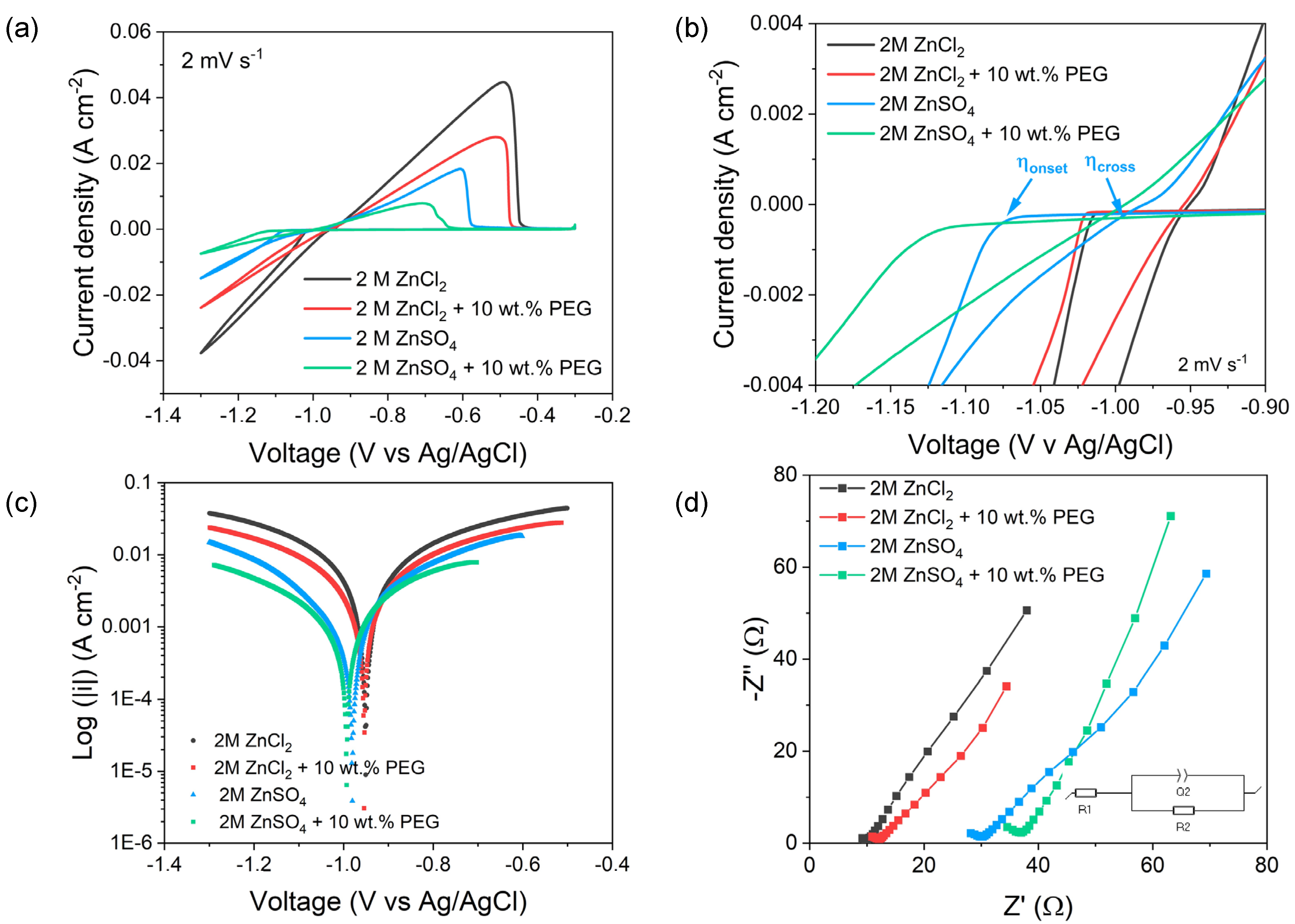
Figure 1. (a) Cyclic voltammetries of Ti3C2Tx-coated electrode in different electrolytes recorded at a scan rate of 2 mV s−1, (b) magnified part of the cyclic voltammetries, highlighting the cross potential and onset potential (an example is pointed out for the 2M ZnSO4 solution), (c) Tafel plots obtained from the cathodic scan of CVs in (a), (d) Nyquist plots of the Ti3C2Tx electrodes in different electrolytes (inset: equivalent circuit used for the fitting).
Applsci 14 00682 g001
Figure 2. SEM images (25 KX) of the Zn structures grown on Ti3C2Tx substrate by Hull cell preparation in: (ac) 2M ZnCl2, (df) 2M ZnCl2 + 10 wt.% PEG400, (gi) 2M ZnSO4 and (jl) 2M ZnSO4 + 10 wt.% PEG400 electrolytes. The corresponding current density value is indicated at the top of each column.
Applsci 14 00682 g002
Figure 3. XRD diffractograms of Zn deposits obtained by Hull cell sample preparation in different electrolytes: (a) 2M ZnCl2, (b) 2M ZnCl2 + 10 wt.% PEG400, (c) 2M ZnSO4, (d) 2M ZnSO4 + 10 wt.% PEG400, varying the applied current density. Insets: magnified portion of each XRD diffraction patterns in the range 35–45°.
Applsci 14 00682 g003
Table 1. Electrochemical parameters extracted by cyclic voltammetries at 2 mV s−1 according to different electrolytes, i.e., 2M ZnCl2, 2M ZnCl2 + 10 wt.% PEG400, 2M ZnSO4 and 2M ZnSO4 + 10 wt.% PEG400.
2M ZnCl22M ZnCl2 + 10 wt.% PEG4002M ZnSO42M ZnSO4 + 10 wt.% PEG400
|ip,plat|(A cm−2)0.0370.0240.0140.007
Qplat (C)5.963.701.810.84
Ip,strip (A cm−2)0.0440.0270.0180.008
Qstrip (C)5.863.701.750.78
η (mV)627180121
i0 (mA cm−2)10.946.662.951.47
Table 2. Ionic conductivities of the different electrolytes, as measured by a conductivity meter probe at room temperature.
2M ZnCl22M ZnCl2 + 10 wt.% PEG4002M ZnSO42M ZnSO4 + 10 wt.% PEG400
σ (mS cm−1)100.268.15429.1
Table 3. R1 and R2 values obtained from fitting the semicircle in Nyquist plots with the equivalent circuit reported in Figure 1d. The R2, Eq.3 is the charge transfer resistance calculated using Equation (3) and i0 values reported in Table 1.
2M ZnCl2 2M ZnCl2 + 10 wt.% PEG400 2M ZnSO4 2M ZnSO4 + 10 wt.% PEG400
R14.987.215.7123.27
R25.555.8510.5514.94
R2, Eq.34.427.3310.6916.45
Disclaimer/Publisher’s Note: The statements, opinions and data contained in all publications are solely those of the individual author(s) and contributor(s) and not of MDPI and/or the editor(s). MDPI and/or the editor(s) disclaim responsibility for any injury to people or property resulting from any ideas, methods, instructions or products referred to in the content.

