Abstract
Intense physical activity and high ambient temperature cause construction workers to be exposed to an increased risk of overheating, especially in the summer season. Personal cooling systems have great potential to support workers’ thermoregulation and reduce this risk. In particular, solutions based on the thermoelectric effect can provide high cooling effectiveness and ergonomics at the same time. In this paper, a newly developed active clothing solution with flexible thermoelectric modules intended for outdoor activities is presented. The active clothing was subjected to utility tests on a treadmill under laboratory conditions with the participation of potential end users. A comparison of results from cooled and uncooled places indicated a reduction in local skin temperature of as much as 2.7 °C. Moreover, a gradual decrease in temperature in the uncooled place during the experiment was observed. Based on the positive results from this evaluation, the personal cooling system was integrated into active clothing within the ASSIST-IoT NGIoT reference architecture. This allows contextual and personalized adjustment of the cooling power to be provided using AI techniques and, additionally, by using data from a weather station and a smartwatch. Training procedures and models for the AI system are proposed, with special attention paid to the privacy aspect.
1. Introduction
The problem of thermal load in the work environment due to the exposure to a hot microclimate still persists for a significant number of people and is expected to increase significantly with climate change [1]. Construction workers are one of the groups experiencing this problem due to their work outdoors, often in full sun. It is worth mentioning that 2022 was the warmest year on record for a large part of Europe [2]. According to the analysis conducted by Ballester et al. [3], as many as 61,672 deaths in Europe between 30 May and 4 September that year were related to heat. Therefore, it is recommended that construction companies provide additional solutions that will support workers’ thermoregulation.
From a technical point of view, preventing excessive thermal load while working outdoors is particularly problematic. In this case, in order to guarantee cooling effectiveness without negatively affecting ergonomics, the use of a personal cooling system seems to be the only possible solution. There are several cooling mechanisms that, when integrated with clothing, can significantly reduce a worker’s thermal load. In particular, non-electric and electric cooling can be distinguished [4]. There are several methods currently available to provide personal cooling [5,6]; however, considering the recent technological revolution that has led to Industry 4.0, including Construction 4.0 [7], particular attention should be paid to electronic solutions that enable their integration within Internet-of-Things architectures in the work environment (a construction site, in this case).
A promising direction in this field is the application of thermoelectric modules (TEMs) whose operation is based on the Peltier effect [8]. The temperature difference created between the two sides of these TEMs can be used for either cooling or heating [9]. Since the cooling intensity of TEMs is adjusted through their electric supply power, their control by electronic devices is simple, direct, and efficient, without the need for any intermediate stages of energy conversion. The use of moving mechanical parts can be avoided, reducing the system weight and size and minimizing energy consumption, as well as increasing product reliability and service life. Supply voltages may be as small as just a few volts, making them safe for use in clothing and easily supplied from low-voltage energy storage devices, such as powerbanks. Recently, TEMs have been offered as flexible items, making their integration with clothing easy without compromising the ergonomic properties of the latter [10,11,12]. This feature is particularly important when TEMs are implemented into protective clothing as it makes it possible to avoid loose or protruding elements that could easily get caught, e.g., by operating tools or machines. In addition, TEMs are considered to be an environment-friendly alternative to other cooling technologies, which is an additional advantage considering the climate crisis [13].
In spite of the great potential of TEMs in personal cooling, there have been only a few solutions using this technology so far. Moreover, scientific reports related to the application of flexible TEMs mainly come from recent years, which additionally confirms the novelty of this research direction. One of the wearable thermoelectric devices for personal cooling was presented by Hong et al. [12]. They proposed a vest and a band intended for use directly on the body. Using the developed devices, a temperature reduction of 5 °C was achieved, depending on the physical activity performed. A T-shirt with flexible TEMs and heat sinks containing phase-change materials was proposed by Huo et al. [14]. The authors confirmed the cooling capability of the developed clothing in tests carried out in 23 °C and 32 °C using a thermal-imaging camera. The reduction in skin temperature underneath the TEM reached over 8 °C. Moreover, a reduction in skin temperature next to the TEM was also observed. On the other hand, Xu et al. [15] used the thermoelectric effect for indirect body cooling, where the role of a TEM was to cool a liquid distributed in the garment, while the reduction in skin temperature resulted from the circulation of the liquid. In this case, during the tests, a temperature reduction of about 2.7 °C was observed.
TEM-based personal cooling systems (PCSs) offer similar or even higher maximum reductions in skin temperature compared with other types of active PCSs described in the literature (Table 1), such as liquid-based [16,17] or PCM-based systems [18,19,20] without TEMs. At the same time, the total weight (including batteries) of TEM-based solutions may be much lower for comparable operating times. It is related to both the low mass of active components and to the high possible value of the coefficient of performance (COP), which helps to reduce the required battery capacity. A low total weight of the system is, in turn, important in terms of the metabolic cost for the user who carries the PCS [18]. The above observations apply especially to PCSs with flexible TEMs that are in direct thermal contact with the skin [12,14] and, to some extent, to other PCSs where TEMs are used to cool down a circulating liquid [15,21,22].

Table 1.
Different active PCS and their parameters.
Importantly, the electronic sub-system already on board for TEM control may be used for several additional purposes. For example, microcontroller modules usually offer communication interfaces. The TEM controller may thus become a node of an IoT system with little or no additional hardware; it is only necessary to develop suitable software extensions. If low-power communication technology is used, energy-storage requirements will not considerably increase, as most of the power will still be consumed by the TEMs. Moreover, the ultra-wideband (UWB) technology has embedded features that enable, i.e., node tracking and real-time data collection. This makes it particularly well-suited for the integration of TEM-based protective clothing within smart work environments oriented toward improved worker safety, but such a concept has not been considered so far.
For the above reasons, a model of active clothing with Peltier-based PCS was developed and integrated within a Next-Generation Internet-of-Things (NGIoT) reference architecture. The integration enables a seamless functioning of the PCS within a larger Cloud-Edge-IoT ecosystem, leveraging artificial intelligence (AI) methods. Moreover, by using the interoperability mechanisms of the NGIoT platform, AI can use measurements from other sensors for an intelligent control of the PCS. In the considered case, this includes a locally installed weather station and a low-cost smartwatch for heart-rate monitoring [23].
The aim of this contribution is to discuss selected results of the PCS validation tests, as well as its expected functioning in the Smart Safety of Workers pilot study within the ASSIST-IoT reference architecture (an EU Horizon 2020 project) [24].
2. Materials and Methods
2.1. Test Objects
For the purpose of this research, a model of active clothing with a personal cooling system was developed and tested using appropriately selected high-visibility protective clothing that meets the requirements of EN ISO 20471 [25] (Figure 1). Both the model of the active clothing and the protective clothing worn underneath it were produced by PW Krystian sp. z o.o. The design of the developed model was based on the conclusions from previously conducted tests [5,26].
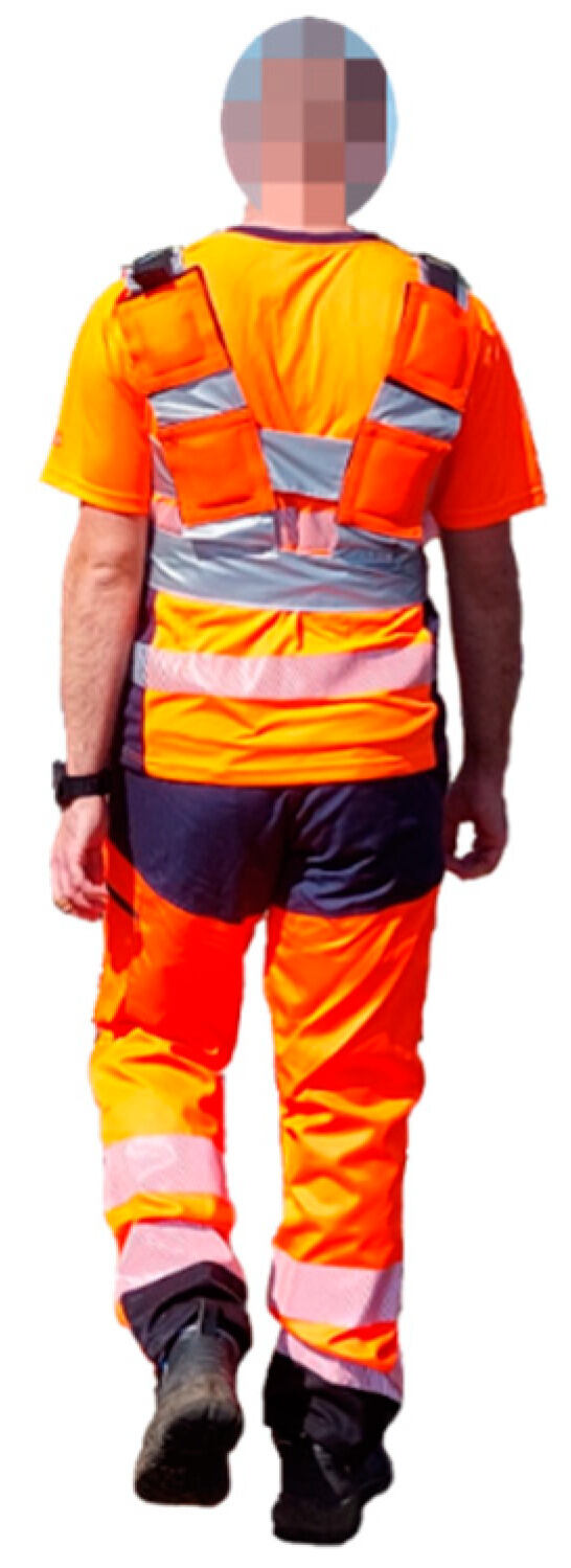
Figure 1.
Tested object: active clothing with PCS worn over high-visibility protective clothing.
2.1.1. Clothing Set Design
The developed model of active clothing with a TEM-based PCS (Figure 2) consists of a vest with integrated TEMs, six heat sinks, a controller, an undergarment temperature sensor, a powerbank, and a pocket for the controller. The cooling function is performed by six flexible FTE-01 (TEGway) thermoelectric modules. Each of them is composed of many elementary cells, based on bismuth and tellurium (BiTe), within a small surface area. These cells are connected mechanically, through a flexible plastic filling, as well as electrically. The heat sinks use a super-absorbent non-woven SAF Type 2644 fabric, and the top and bottom fabrics of these heat sinks were selected so as to have the lowest possible thermal resistance (0.012 m2K/W and 0.006 m2K/W, respectively) to maximize heat removal from the hot side of the modules by evaporation. The vest is made of retroreflective tapes of 7 cm width, with adjustments on the arms and at the front. The latter enable the vest to be fitted to the user’s body. The TEMs are integrated with the vests by sewing, while the heat sinks are mounted on them by means of Velcro tape. The powerbank used in this work is a standard device with a 5 V output. It has a capacity of 15 Ah, which corresponds to an energy of 55.5 Wh at its nominal internal voltage of 3.7 V. The controller is described in detail in Section 2.1.2.
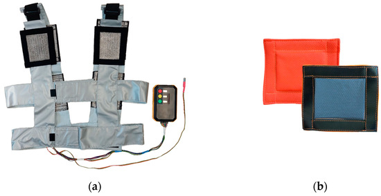
Figure 2.
Tested objects: (a) active clothing with PCS intended to be worn over the high-visibility protective clothing; (b) heat sink (top side and bottom side).
To guarantee the safety of the potential users of the active clothing, the design was made to be compatible with a T-shirt and trousers (Figure 3) of high visibility (class 1 and class 2, respectively, according to EN ISO 20471 [25]). This has been achieved by arranging the retroreflective stripes on the vest so that two horizontal retroreflective stripes encircling the torso are kept visible even when the T-shirt is covered by the vest (see Figure 1).
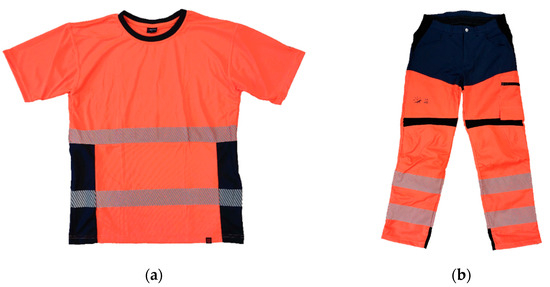
Figure 3.
High-visibility protective clothing intended for a use with active clothing: (a) T-shirt; (b) trousers.
2.1.2. Dedicated Electronic Controller for TEM Power Supply
An essential part of the developed PCS is the controller, which is a dedicated embedded electronic system whose main role is to provide a controlled electric power supply to the TEMs. The electric energy is drawn from a powerbank with a 5 V output voltage. The controller is connected to an undergarment temperature sensor, and it executes a program for the temperature and power regulation [5]. This regulation is performed independently in each of its three output channels, with two TEMs connected to each channel.
The block diagram of the electronic system is shown in Figure 4. Its main components are:
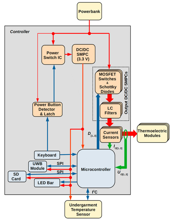
Figure 4.
Electronic controller block diagram (digital signals: blue; analog signals: green; power paths: red).
- an auxiliary DC/DC switched-mode power converter (SMPC) with an integrated analog controller—to supply the control electronics with a 3.3 V voltage;
- a semiconductor power switch—for turning on and off the auxiliary SMPC;
- a power-button-pressing detector with a latched output state—for controlling the power switch;
- three digitally controlled output DC/DC SMPCs (one per output channel)—for supplying the TEMs in each channel;
- current sensors (one per channel) in the form of shunt resistors with dedicated voltage amplifiers—for measuring the channel output currents;
- a microcontroller;
- a three-button keyboard;
- a light-emitting diode (LED) bar display;
- a Micro Secure Digital (SD) card interface—for configuration and measurement data storage;
- a UWB radio module—for communicating with the rest of the smart work environment infrastructure using the NGIoT architecture.
The output power converters employ the buck topology, with each one containing a MOSFET (Metal-Oxide-Semiconductor Field-Effect Transistor) switch, a Schottky diode, and an LC (inductance–capacitance) filter. The MOSFET switches are driven by pulse-width-modulated (PWM) signals generated by the microcontroller, with variable duty cycles D[1..3] that are continuously updated according to the control program. The LC filters ensure constant output voltages with low ripple, which is crucial for an efficient TEM operation.
The microcontroller measures the output channel voltages Uo[1..3] and currents Io[1..3] using a built-in analog-to-digital converter (ADC) to obtain feedback information on the output power in each channel. It also communicates with the undergarment temperature sensor via the Inter-Integrated Circuit (I²C) interface as well as with the SD card and the UWB module via the Serial Peripheral Interface (SPI) bus. Two buttons of the keyboard are polled by the microcontroller to check if the user wants to increase or decrease the cooling intensity. The current setting of the TEM power levels is indicated on the LED bar display.
The TEMs operate in an alternating mode, as described in more detail in [5]. The supply power per module is either regulated to obtain the requested temperature, with a maximum limit of 1.5 W, or to bring it down to a standby value of 0.5 W. The duration of each of these phases is 60 s.
2.1.3. Thermoelectric Module Arrangement and Supply Voltage
A separate DC converter has been provided for each of the three TEM pairs to minimize the electric supply power discrepancies between them, which is caused by their resistance spread. Within each pair, a series connection might initially seem to be more advantageous because of the higher converter output voltage, which is equal to the sum of the two TEM voltages (Figure 5a):
To simplify, both TEM voltages have been assumed to be approximately equal at some value UTEM. The converter must deliver to the TEMs a power equal to:
Uo = UTEM1 + UTEM2 ≈ 2UTEM,
Po = PTEM1 + PTEM2 = Io Uo.
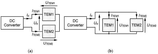
Figure 5.
Possible TEM connection topologies within each pair: (a) in series; (b) parallel.
The currents of the two TEMs are equal, i.e., ITEM1 = ITEM2 = Io, so this common current is expressed by:
Io = (PTEM1 + PTEM2)/(2UTEM),
In contrast, in the parallel arrangement (Figure 5b), all the voltages are equal, i.e., UTEM1 = UTEM2 = Uo, while the converter’s output current is the sum of the two TEM currents:
which is twice the value yielded by (3).
Io = ITEM1 + ITEM2 = PTEM1/VTEM + PTEM2/UTEM = (PTEM1 + PTEM2)/UTEM,
The higher output current in the parallel connection results in two principal drawbacks of this option:
- higher necessary current ratings of the converter’s components; hence, their greater cost and size, as well as, most probably, power losses;
- higher power losses in common wiring, making the efficiency lower and the battery operating time shorter. It must be noted that with worn electronics, the possibility of decreasing losses by increasing the wire diameters is limited by the requirement of flexibility.
Nevertheless, when an electronic system is to be integrated with clothing, one must consider that live parts may enter into contact with the skin, either directly (e.g., due to damage to the insulation) or through humidity. When cooling is needed, sweating is especially likely to occur as a natural mechanism of body temperature regulation, and sweat is highly conductive electrically due to the content of NaCl and KCl, which are strong electrolytes [27].
The IEC 60479-1 standard [28] contains data that may be used to determine safe voltage levels for a number of specific cases. As justified above, saltwater-wet conditions should be considered, corresponding to a 3% water solution of NaCl, which, according to the standard, may represent sweat. As far as physiological effects are concerned, only the DC-1 zone may be allowed for worn electronics, where a slight sensation is possible upon rapid changes of current flow, such as by switching the TEMs on or off. The current threshold between the DC-1 zone and the DC-2 zone (where involuntary muscle contractions occur) is given as 2 mA.
The standard provides tabulated values of a reference total body resistance Rt(ref) as a function of the touch voltage Ut. It is reasonable to use data for a small contact-surface area, which is set at 100 mm². To obtain the most conservative voltage limits, data applicable to the 5th percentile of the population having the lowest body resistance were used. From the point of view of physiology, the critical path is the one between the left hand and the chest, where the resistance Rt is 63% of the reference one.
To calculate the touch voltage corresponding to a given current, the Rt versus Ut relationship was approximated using a function that proved suitable for all the cases included in the standard (see Figure 6):
Rt = exp(p4 (0.5 – atan(p3 (ln Ut – p2))/π) + p1).
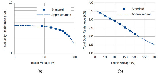
Figure 6.
Total body resistance for the path between the left hand and the chest, for a small contact-surface area and saltwater-wet conditions, as provided in [28] and approximated with Equation (5): (a) logarithmic scale; (b) linear scale.
The constant parameters p1 through p4 were obtained by data fitting in Octave using the nonlin_curvefit function from the optim package. For a Ut below the lower end of the data range, linear extrapolation was applied. Using these data and the fzero function, the left-hand-to-chest voltage corresponding to the current threshold of 2 mA was determined to be 7.1 V, with an estimated total body resistance of 3.53 kΩ.
From an electrical point of view, TEMs are of a resistive nature, exhibiting some resistance RTEM, ranging between 4.5 Ω and 5.9 Ω for the modules used. Therefore, their electric supply power follows Joule’s law:
PTEM = UTEM2/RTEM.
For the target maximum supply power of 1.5 W, the worst-case TEM voltage was estimated at 3.0 V, based on measurements.
The above value would make it possible to connect two TEMs in series without exceeding the 7.1 V limit. However, this would make it impossible to use a standard 5 V output powerbank for energy storage without employing a step-up DC converter. Such converters have lower efficiencies than the step-down (buck) topology, which can only be applied when TEMs are connected in parallel so that their total voltage is lower than that of the powerbank. For this reason, the parallel arrangement was ultimately selected.
2.2. Research Methodology
The aim of the research was to evaluate the reduction in thermal discomfort by the developed active clothing under simulated conditions of use in a laboratory environment. These tests are a first step toward an integration of the active clothing within an NGIoT architecture. Laboratory conditions were preferred over field ones to guarantee their stability and repeatability. Six workers participated in the tests as potential users of the active clothing. The average age, height, and weight of the participants were (29.5 ± 7.58) years, (179.33 ± 3.20) cm, and (80.00 ± 10.49) kg, respectively. Before the tests, the volunteers were informed about the research purpose and plan and gave their informed written consent to participate. The tests were carried out at similar times of the day (morning hours), with different participants on each particular day.
2.2.1. Test Conditions
The tests of the active clothing were carried out in the Research and Demonstration Laboratory in the Department of Personal Protective Equipment at the Central Institute for Labour Protection—National Research Institute, at a temperature of 25 °C and a relative humidity of 65%. This ambient temperature was selected on the basis of survey responses, where the majority of respondents indicated the need for cooling as starting from 25 °C [29]. Test participants were dressed in the dedicated protective clothing described in Section 2.1.
2.2.2. Measured Parameters
The tests included the measurement of physiological parameters of the research participants and the collection of their subjective thermal sensations. In terms of the former, local skin temperature was measured in cooled places (under the thermoelectric modules) and in uncooled places (next to the thermoelectric modules) (Figure 7). Local skin temperatures in cooled places were measured under the modules located on the right side of the chest and under the module located on the left shoulder blade. The measurement of local skin temperature in uncooled places was carried out in the center of the chest and between the shoulder blades at the same level as the temperature in cooled places. AC1913-A sensors from Rotronic were used for these measurements because of their small size, so as not to create an additional distance between the active-clothing user’s skin and the TEM. The measured temperature was recorded using the HygroLog HL-NT2-D recorder and the HL-DS-U2 docking station from Rotronic, which allows four AC1913-A sensors to be connected simultaneously.
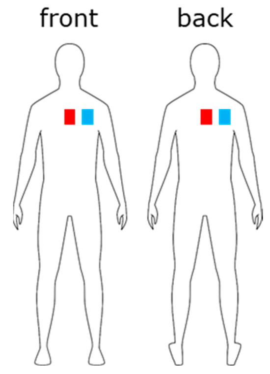
Figure 7.
Locations of the local skin temperature sensors on the front and on the back, with the cooled places marked in blue and uncooled places in red.
The obtained local skin temperatures extracted at every fifth minute of the test were subjected to a statistical analysis using the STATISTICA 13.1 PL software in order to determine the statistical significance of the obtained differences. Before starting the analysis, the normality of the distribution of the variables was checked using the Shapiro–Wilk test. The homogeneity of variances was checked using the Levene’s test. The Student’s t-test was used to assess the statistical significance of differences between the results obtained at cooled and at uncooled places. The significance level was set at 0.05.
The participants assessed the sensations related to their overall thermal comfort using the scale presented in Table 2.
Table 2.
Scale for the rating of overall thermal comfort [30].
2.2.3. Research Procedure
Before starting the tests, the clothing set was acclimatized in an air-conditioned laboratory room at a temperature of 23 °C. The participants stayed in the same conditions for 30 min before the test to stabilize their physiological parameters and to minimize the influence of external factors thereon. The heat sinks were soaked in water at a room temperature of approximately 23 °C and then mounted on the TEMs. After this preparatory phase, the participants went directly to the laboratory room where the tests took place. Local skin temperature recording was started 5 min in advance to confirm the stability and the repeatability of the test conditions.
The laboratory research procedure included each participant performing a physical activity over 15 min intervals with 5 min breaks between them. The activity involved walking on a Zebris FDM-THM-M-3i treadmill from Zebris Medical GmbH at a speed of 5 km/h, corresponding to a high physical exertion. Figure 8 shows the detailed test procedure. During the study, the thermal comfort assessment by the participant was collected every 5 min.
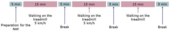
Figure 8.
Research procedure phases.
3. Results
Figure 9 shows graphs of the average temperature in cooled places (under modules) and in uncooled places (next to modules) on both the chest and the shoulder blades. The greatest difference in the measured skin temperature between the cooled and uncooled places, amounting to 2.66 °C, was recorded on the back around the 24th minute of the test. For the chest, the largest difference of 2.34 °C was recorded around the 44th minute of the study and a difference of 2.25 °C around its 13th minute. Qualitatively, the cooling effect was maintained throughout the entire study period. At the end of the study, the measured temperatures on the chest and the shoulder blades were approximately 1 °C lower than at the beginning. The measured temperature in the cooled place on the chest remained at a relatively similar level from about the 10th minute of the test, ranging from 31.2 °C to 32.0 °C, which is close to the thermally neutral state and confirms that the system operated as intended. The statistical analysis showed that in the case of the chest, the temperature difference between the cooled and the uncooled place was statistically significant only in the 20th minute of the test. For the back, statistically significant differences occurred at the 10th, 15th, 20th and 25th minutes of the test.
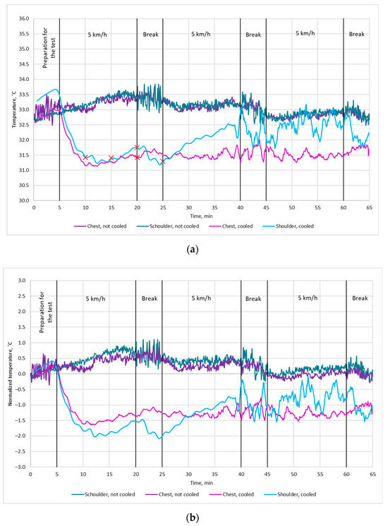
Figure 9.
Measured local skin temperatures in cooled and uncooled places: (a) absolute; (b) normalized. ✕ indicates statistically significant differences at a significance level <0.05.
It is noteworthy that the local skin temperatures measured in places not directly cooled, i.e., next to the module, increased in the initial phase (up to approx. 25 min), but then they decreased. This is a very positive result, indicating that although thermoelectric modules collect heat from the human body locally, a cooling effect is also observed in other places.
When the PCS was active, the average rating of the thermal sensations oscillated around the value of 0, mostly between −1 and 1, corresponding to “slightly cool”, “neutral”, and “slightly warm” (Figure 10). The ratings given after the breaks (i.e., in the 25th and the 45th minute of the test) indicate an increased feeling of cooling and, thus, an improvement in thermal comfort. At these moments, the average ratings were the lowest obtained during the entire study.
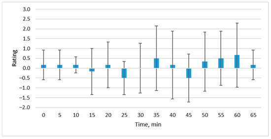
Figure 10.
Participants’ assessment of thermal sensations using the scale from Table 2.
The average resistance of the TEMs was determined to be 5.2 Ω. A single TEM current was therefore 0.54 A at maximum in the regulation phase, when the output power was 1.5 W per module, and 0.30 A in the standby phase. The respective voltage values were 2.9 V and 1.7 V, respectively. The input power from the powerbank was 11.40 W and 3.69 W, respectively. As mentioned in Section 2.1.2, the phase durations were equal, so the average power consumption was 7.55 W.
4. Integration of the PCS with the ASSIST-IoT Reference Architecture
4.1. ASSIST-IoT Smart Worker Safety System
The results of the laboratory tests provided a basis for further work related to the integration of the PCS within the broader Cloud-Edge-IoT ecosystem, using the ASSIST-IoT reference architecture [24]. Figure 11 presents an overview of the proposed system in the context of the ASSIST-IoT Smart Safety of Workers pilot study. The PCS communicates with Gateway Edge Nodes (GWENs) located on the construction site using the UWB technology. In the virtualized (Kubernetes) environment provided by the GWENs, several ASSIST-IoT enablers and other components are deployed. The enablers are easily reusable software components, each providing a set of generic functionalities. The streams of data to and from the PCS are routed efficiently on the edge using the Edge Data Broker enabler. The measurements from the weather station and the smartwatch take a similar route—the smartwatch is paired via Bluetooth Low Energy to a UWB location tag that then relays the heart-rate measurements. The Location Tracking enabler interfaces with the UWB location tag and sends the measurements (including the user’s heart rate) to the Edge Data Broker enabler. The data from all sensors (including the PCS) are annotated semantically using the Semantic Annotation enabler to enable interoperability between devices. The Semantic Repository enabler plays a supporting role by managing the needed data models, such as domain ontologies, or the annotation configuration for the Semantic Annotation enabler.
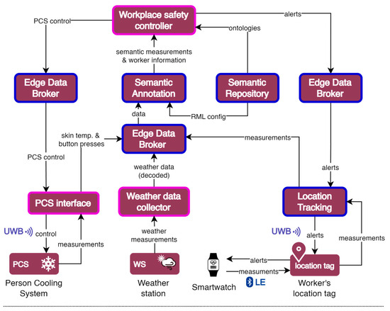
Figure 11.
Overview of the proposed system, integrating the PCS with the rest of the construction site infrastructure, using the ASSIST-IoT reference architecture.
The collected measurements are streamed to the Workplace safety controller, which is responsible for determining the adequate cooling power at a given moment considering the current conditions, using AI methods. Moreover, it remembers user preferences and takes them into account in future decisions. The AI can issue commands to the PCS (to increase or decrease the cooling power) and send alerts to the user, which are displayed on the smartwatch. The commands and the alerts are similarly routed via the Edge Data Broker enabler.
4.2. Concept of AI-Based Personalized Cooling
Ensuring the privacy of the user’s biometric parameters in the system (Figure 11) is a very challenging task. It should be stressed here that one of the main requirements for the system is for it to be able to personalize the cooling power based on the user’s preferences. Although there is some literature on preserving the privacy of users in personalized learning systems [31,32,33,34], those studies mostly tackle a different formulation of the problem. Usually (e.g., in federated learning systems), we can assume that the model can be trained on a device fully controlled by the user, and then the model’s parameters can be sent in a private way to the server (e.g., using differential privacy [35]). This is not the case in the application considered in this work—the user, in fact, does not fully control any device in the system. The PCS itself has very little computational capacity, and thus any work must be deferred to the GWENs. However, the user is not assigned to any specific GWEN—by moving around the construction site, the worker can encounter dozens of different GWENs. Therefore, there must exist some centralized location (a server) that stores the personal preferences of users.
Bearing in mind the presented limitations of the use case, an AI system was designed that aims to maximize the users’ privacy while retaining the element of personalization (Figure 12). The proposed system hinges on the GWEN not storing any data permanently, which can be guaranteed by adequate routing rules in the Edge Data Broker. The GWEN gathers four types of data: the user identifier (needed for personalization), the cooling power (target variable), weather data describing the environmental conditions, and the user’s biometric data. It is the biometric data that are particularly sensitive and thus must not be associated with the user identifier (as depicted in the lower half of Figure 12). We can, however, build two separate models: one which includes the user’s identifier but not biometric data, and another which includes the biometric data but not the identifier. This way, the system would be able to learn (1) the user’s preferences depending on the outside conditions, and (2) the aggregated preferences of all users depending on the outside conditions and the biometric parameters. This, of course, limits the potential for personalization, but still allows the system to consider all available measurements when making the decision. The presented models can be implemented using any regression technique. Particularly useful should be the k-nearest neighbors algorithm due to its very elastic training procedure (simply adding an observation to the database) and flexibility in the face of non-linear relationships.
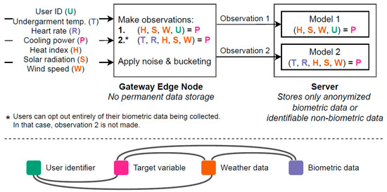
Figure 12.
Upper half: proposed training procedure. The GWEN makes two observations, adds noise and bucketing, and sends them separately to the server to be included in the respective models. Lower half: types of data encountered in the use case and the possible associations that can be made between them to preserve the user’s privacy.
It should be stressed here that although the separation of the user identifiers and the biometric data does improve the privacy of the users, it could still be compromised. The two models share the target variable and three of their inputs (the weather data). It might be possible to work out the correspondence between the user and their biometric data if there is a direct, one-to-one match between the weather data and the cooling power in both models. Although formally determining the degree of privacy given by such a system is out of the scope of this contribution, additional provisions can be made to increase the privacy level. Firstly, the GWEN can apply noise and bucketing to the observed data independently for each model. This reduces the chance that a direct correspondence between the models can be established, especially when there are many users. Furthermore, the two models can be updated asynchronously. The users can also opt out entirely of their biometric data being collected, thus not contributing to the second model. This would mean that predictions can be made about the cooling power based only on the environmental conditions, but still maintain a degree of personalization. Nonetheless, establishing the level of privacy in this system should be the subject of future work, using frameworks such as k-anonymity [36], ε-differential privacy [37], or others [38]. Figure 13 presents how the AI system can use the learned observations to determine the adequate cooling power at a given moment. The GWEN makes two separate requests to the server, to which the same privacy-preserving measures as with learning can be applied (noise, bucketing, asynchrony). The two models give two answers about the cooling power to be applied, which are then aggregated by some function f. This function can be as simple as an arithmetic mean, or, for example, an average weighted by the confidences of the models. Here the biometric data collection is also optional, and the user can opt out of it. Alternatively, the inference could be performed on the edge (in the GWEN), allowing the user’s biometric data to be used with no risk of compromising their privacy.
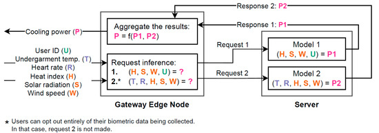
Figure 13.
Proposed inference procedure. The GWEN sends the requests to two models independently and then aggregates them.
5. Discussion
Laboratory utility tests have shown that the developed active clothing is able to reduce the local skin temperature by up to 2.66 °C during intense physical activity and that the cooling effect was maintained throughout the entire study period. This reduction was in between the results of other personal cooling systems presented in the literature [14,15], which makes it possible to positively evaluate the developed solution. It was lower than the one yielded by the T-shirt proposed by Huo et al. [14]. This may be due to additional fabrics applied under the proposed active clothing model, which, in the considered use case, were required for the worker’s safety. Fabrics constitute additional layers of thermal insulation that decrease heat conduction between the skin and the TEM.
A positive effect of the applied cooling was also visible in users’ sensations as thermal comfort sensation ratings decreased during the experiment to below the initial value despite the physical activity being performed. The lowest ratings, being a result of both the cooling effect and lower work expenditure, were observed during the breaks. The influence of the physical activity performed by the PCS’s user on its performance was also noticed by Hong et al. [12].
Skin temperature is one of the physiological indicators used for the evaluation of the human thermal state [39,40]. Its mean value of about 33 °C is considered to be comfortable [41]; however, local skin temperatures on various body parts can differ significantly [42]. The obtained results show that, as a result of the application of active cooling, local skin temperature values both in a cooled place and in an uncooled one (both on the torso) were kept close to the comfort one.
Moreover, the applied cooling positively affects the user’s thermal comfort sensations through the reduction in the temperature measured outside the TEMs. This observation is consistent with the results reported by Huo et al. [14], who argue that such an effect results from the thermal conduction of the skin and the circulation of the cooled blood. This outcome is particularly important in the context of the simulations performed by Baek et al. [43], who concluded that local cooling with a use of a TEM may only provide limited protection against extreme thermal environments. However, in that study, the TEM was used for cooling the air in a PCS, not the human skin directly [44]. Heat transfer mechanisms from the skin are different in both cases, i.e., direct conduction in this work versus convection of a cooling medium in [43].
According to the body map created by Luo et al. [45], the cheek, back of neck, and seat area are the body regions most sensitive to cooling. However, considering the ergonomics, workers’ preferences, and requirements resulting from the working conditions, the body regions selected to be covered by TEMs in the proposed PCS appear to be a good compromise between sensitivity to cooling and comfort of use. Moreover, it has been proved that local cooling can significantly contribute to overall thermal comfort sensations [46,47,48]. Based on their research performed with 30 volunteers, Belyamani et al. [49] also proved that local cooling provided by a wristband, besides influencing the overall thermal comfort sensation, can lead to a reduction in negative emotions and a rise in positive emotions.
Under the maximum observed power consumption of 7.55 W, the 15 Ah powerbank used can supply the system for 7.35 h. This is sufficient for a typical work shift, since the PCS is normally not constantly operated at full power.
Based on earlier measurements [50], the heat flux through the TEMs for a current of 0.30 A (corresponding to an electric power of 0.48 W) is 0.99 W, and it may be approximated by linear regression as 1.24 W for a current of 0.54 A (corresponding to an electric power of 1.50 W). This gives a maximum COP value of 2.1 and a minimum average one of 1.1, which is consistent with results obtained in other works for similar temperature reductions, as presented in Table 1.
Extending the functionality of the PCS by means of its integration with the ASSIST-IoT reference architecture to include an automatic control using heart rate, undergarment temperature and environmental data will allow it to better adapt its operation to prevailing conditions. However, the use of biometric data must respect the user’s privacy. The proposed approach does not directly link the user’s ID to such data, preventing their unambiguous identification by third parties.
6. Conclusions
The tests of the PCS model showed that the developed solution, including the dedicated electronic controller, can effectively reduce the local skin temperature and stabilize its value even outside the TEMs at the appropriate level, thus positively affecting the subjective sensation of overall thermal comfort. The obtained results are promising and encourage further research aimed at (1) a comprehensive evaluation of the PCS, including an analysis of its influence on human thermal states expressed by differences in mean skin temperature and body temperature, and an ergonomics evaluation under simulated utility conditions; (2) increasing energy effectiveness; (3) improving wearability and maintenance; as well as (4) adjusting to the requirements of other specific working environments (e.g., glass factory or mine).
The implementation of three separate output channels of the electronic controller provided a greater coherence between different TEMs in terms of cooling power. The parallel arrangement of TEMs in pairs decreased their required maximum supply voltage to about 3 V, which enhanced the electrical safety of the user even in the presence of sweat. Moreover, this allowed a 5 V powerbank to be used for energy storage without requiring a step-up power converter.
The integration of the developed PCS model within ASSIST-IoT will increase the level of automation of the former, reducing the required amount of user interaction. The use of biometric data and environmental data will allow the cooling intensity to be adjusted to the current worker’s activity and site conditions. Moreover, taking into account possible changes to system controls made by the user will make it possible for the system to learn about their individual preferences, and the use of AI to adapt cooling to these changes will allow it to find appropriate cooling settings. The proposed architecture takes special care to preserve the user’s privacy while using data from several sources to adjust the cooling power in real time.
7. Patents
The described active clothing with PCS is the subject of a utility model application number W.131106 titled “Szelki chłodzące” at the Patent Office of the Republic of Poland (UPRP).
Author Contributions
Conceptualization, A.D., M.K., Ł.S., B.P. and P.S.; methodology, A.D. and M.K.; software, Ł.S., B.P., P.S. and M.K.; validation, A.D. and M.K.; investigation, A.D. and M.K.; resources, A.D.; data curation, A.D. and M.K.; writing—original draft preparation, A.D., M.K., Ł.S., B.P. and P.S.; writing—review and editing, A.D., M.K., Ł.S., B.P. and P.S.; visualization, A.D., M.K., Ł.S., B.P. and P.S.; supervision, A.D.; project administration, A.D.; funding acquisition, A.D. All authors have read and agreed to the published version of the manuscript.
Funding
This paper is published and based on the results of a research task carried out within the scope of the fifth stage of the national program “Improvement of safety and working conditions” supported by resources from the National Centre for Research and Development; task no. III.PB.09, titled “Development of the protective clothing with an active cooling function based on the thermoelectric effect (Peltier modules)” (with the Central Institute for Labour Protection—National Research Institute as the program’s main coordinator); and project ASSIST-IoT, grant number 957258, funded by the European Commission under the Horizon 2020 program.
Institutional Review Board Statement
Ethical review and approval were waived for this study since the experiments carried out were not classified as medical research and they did not involve more than a minimal risk to the subjects.
Informed Consent Statement
Informed consent was obtained from all subjects involved in the study.
Data Availability Statement
The data presented in this study are available on request from the corresponding author. The data are not publicly available due to privacy.
Conflicts of Interest
The authors declare no conflicts of interest.
References
- Kjellstrom, T.; Maître, N.; Saget, C.; Otto, M.; Karimova, T. Working on a Warmer Planet: The Effect of Heat Stress on Productivity and Decent Work; International Labour Organization (ILO): Geneva, Switzerland, 2019. [Google Scholar]
- ESOTC 2022. Extreme Heat. Available online: https://climate.copernicus.eu/esotc/2022/extreme-heat#6ccc1ccb-aabc-4716-b375-d77d9620e9cb (accessed on 16 November 2023).
- Ballester, J.; Quijal-Zamorano, M.; Méndez Turrubiates, R.F.; Pegenaute, F.; Herrmann, F.R.; Robine, J.M.; Basagaña, X.; Tonne, C.; Antó, J.M.; Achebak, H. Heat-Related Mortality in Europe during the Summer of 2022. Nat. Med. 2023, 29, 1857–1866. [Google Scholar] [CrossRef] [PubMed]
- Ren, S.; Han, M.; Fang, J. Personal Cooling Garments: A Review. Polymers 2022, 14, 5522. [Google Scholar] [CrossRef]
- Dąbrowska, A.; Kobus, M.; Starzak, Ł.; Pękosławski, B. Evaluation of Performance and Power Consumption of a Thermoelectric Module-Based Personal Cooling System—A Case Study. Energies 2023, 16, 4699. [Google Scholar] [CrossRef]
- Dąbrowska, A.; Kobus, M. Directions of development of protective clothing with active cooling function. Occup. Saf. Sci. Pract. 2023, 3, 10–14. (In Polish) [Google Scholar]
- Casini, M. (Ed.) Construction 4.0. Advanced Technology, Tools and Materials for the Digital Transformation of the Construction Industry; Woodhead Publishing Series in Civil and Structural Engineering; Woodhead Publishing: Sawston, UK, 2022; ISBN 978-0-12-821797-9. [Google Scholar]
- Chen, W.-Y.; Shi, X.-L.; Zou, J.; Chen, Z.-G. Thermoelectric Coolers: Progress, Challenges, and Opportunities. Small Methods 2022, 6, 2101235. [Google Scholar] [CrossRef] [PubMed]
- Tian, Z.; Lee, S.; Chen, G. Comprehensive review of heat transfer in thermoelectric materials and devices. Annu. Rev. Heat Transf. 2014, 17, 425–483. [Google Scholar] [CrossRef]
- Ding, J.; Zhao, W.; Jin, W.; Di, C.; Zhu, D. Advanced Thermoelectric Materials for Flexible Cooling Application. Adv. Funct. Mater. 2021, 31, 2010695. [Google Scholar] [CrossRef]
- Wang, Y.; Yang, L.; Shi, X.-L.; Shi, X.; Chen, L.; Dargusch, M.S.; Zou, J.; Chen, Z.-G. Flexible Thermoelectric Materials and Generators: Challenges and Innovations. Adv. Mater. 2019, 31, 1807916. [Google Scholar] [CrossRef]
- Hong, S.; Gu, Y.; Seo, J.K.; Wang, J.; Liu, P.; Meng, Y.S.; Xu, S.; Chen, R. Wearable Thermoelectrics for Personalized Thermoregulation. Sci. Adv. 2019, 5, eaaw0536. [Google Scholar] [CrossRef]
- Sun, W.; Liu, W.-D.; Liu, Q.; Chen, Z.-G. Advances in Thermoelectric Devices for Localized Cooling. Chem. Eng. J. 2022, 450, 138389. [Google Scholar] [CrossRef]
- Huo, W.; Xia, Z.; Gao, Y.; Guo, R.; Huang, X. Flexible Thermoelectric Devices with Flexible Heatsinks of Phase-Change Materials and Stretchable Interconnectors of Semi-Liquid Metals. ACS Appl. Mater. Interfaces 2023, 15, 29330–29340. [Google Scholar] [CrossRef] [PubMed]
- Xu, Y.; Li, Z.; Wang, J.; Zhang, M.; Jia, M.; Wang, Q. Man-Portable Cooling Garment with Cold Liquid Circulation Based on Thermoelectric Refrigeration. Appl. Therm. Eng. 2022, 200, 117730. [Google Scholar] [CrossRef]
- Bartkowiak, G.; Dabrowska, A.; Marszalek, A. Assessment of an active liquid cooling garment intended for use in a hot environment. Appl. Ergon. 2017, 58, 182–189. [Google Scholar] [CrossRef] [PubMed]
- Xu, J.; Chen, G.; Wang, X.; Chen, Z.; Wang, J.; Lu, Y. Novel Design of a Personal Liquid Cooling Vest for Improving the Thermal Comfort of Pilots Working in Hot Environments. Indoor Air 2023, 2023, e6666182. [Google Scholar] [CrossRef]
- Lu, Y.; Wei, F.; Lai, D.; Shi, W.; Wang, F.; Gao, C.; Song, G. A novel personal cooling system (PCS) incorporated with phase change materials (PCMs) and ventilation fans: An investigation on its cooling efficiency. Therm. Biol. 2015, 52, 137–146. [Google Scholar] [CrossRef] [PubMed]
- Qiao, Y.; Cao, T.; Muehlbauer, J.; Hwang, Y.; Radermacher, R. Experimental study of a personal cooling system integrated with phase change material. Appl. Therm. Eng. 2020, 170, 115026. [Google Scholar] [CrossRef]
- Song, W.; Wang, F. The hybrid personal cooling system (PCS) could effectively reduce the heat strain while exercising in a hot and moderate humid environment. Ergonomics 2016, 59, 1009–1018. [Google Scholar] [CrossRef]
- Li, Z.; Zhang, M.; Yuan, T.; Wang, Q.; Hu, P.; Xu, Y. New wearable thermoelectric cooling garment for relieving the thermal stress of body in high temperature environments. Energy Build. 2023, 278, 112600. [Google Scholar] [CrossRef]
- Itao, K.; Hosaka, H.; Kittaka, K.; Takahashi, M.; Lopez, G. Wearable Equipment Development for Individually Adaptive Temperature-conditioning. J. Jpn. Soc. Precis. Eng. 2016, 82, 919–924. [Google Scholar] [CrossRef][Green Version]
- Sowiński, P.; Rachwał, K.; Danilenka, A.; Bogacka, K.; Kobus, M.; Dąbrowska, A.; Paszkiewicz, A.; Bolanowski, M.; Ganzha, M.; Paprzycki, M. Frugal Heart Rate Correction Method for Scalable Health and Safety Monitoring in Construction Sites. Sensors 2023, 23, 6464. [Google Scholar] [CrossRef]
- Szmeja, P.; Fornés-Leal, A.; Lacalle, I.; Palau, C.E.; Ganzha, M.; Pawłowski, W.; Paprzycki, M.; Schabbink, J. ASSIST-IoT: A Modular Implementation of a Reference Architecture for the Next Generation Internet of Things. Electronics 2023, 12, 854. [Google Scholar] [CrossRef]
- ISO 20471:2013; High Visibility Clothing—Test Methods and Requirements. ISO—International Organization for Standardization: Geneva, Switzerland, 2013.
- Dąbrowska, A.; Kobus, M.; Starzak, Ł.; Pękosławski, B. Analysis of Efficiency of Thermoelectric Personal Cooling System Based on Utility Tests. Materials 2022, 15, 1115. [Google Scholar] [CrossRef] [PubMed]
- Liu, G.; Alomari, M.; Sahin, B.; Snelgrove, S.E.; Edwards, J.; Mellinger, A.; Kaya, T. Real-Time Sweat Analysis via Alternating Current Conductivity of Artificial and Human Sweat. Appl. Phys. Lett. 2015, 106, 133702. [Google Scholar] [CrossRef]
- IEC 60479-1:2018; Effects of Current on Human Beings and Livestock—Part 1: General Aspects. IEC—International Electrotechnical Commission: London, UK, 2018.
- Dąbrowska, A.; Kobus, M. Oczekiwania pracowników sektora kolejowego w odniesieniu do odzieży ochronnej z funkcją chłodzenia—Wyniki badań ankietowych. Przegląd Włókienniczy Włókno Odzież Skóra 2023, 2023, 146617. [Google Scholar] [CrossRef]
- ISO 7330:2005; Ergonomics of the Thermal Environment. Analytical Determination and Interpretation of Thermal Comfort Using Calculation of the PMV and PPD Indices and Local Thermal Comfort Criteria. ISO—International Organization for Standardization: Geneva, Switzerland, 2005.
- Zhou, J.; Su, Z.; Ni, J.; Wang, Y.; Pan, Y.; Xing, R. Personalized Privacy-Preserving Federated Learning: Optimized Trade-off Between Utility and Privacy. In Proceedings of the GLOBECOM 2022—2022 IEEE Global Communications Conference, Rio de Janeiro, Brazil, 4–8 December 2022; pp. 4872–4877. [Google Scholar]
- Tan, A.Z.; Yu, H.; Cui, L.; Yang, Q. Towards Personalized Federated Learning. IEEE Trans. Neural Netw. Learn. Syst. 2022, 34, 9587–9603. [Google Scholar] [CrossRef] [PubMed]
- Kaaniche, N.; Laurent, M.; Belguith, S. Privacy Enhancing Technologies for Solving the Privacy-Personalization Paradox: Taxonomy and Survey. J. Netw. Comput. Appl. 2020, 171, 102807. [Google Scholar] [CrossRef]
- Hassan, M.U.; Rehmani, M.H.; Chen, J. Differential Privacy Techniques for Cyber Physical Systems: A Survey. IEEE Commun. Surv. Tutor. 2020, 22, 746–789. [Google Scholar] [CrossRef]
- Dwork, C. Differential Privacy. In Automata, Languages and Programming, Proceedings of the 33rd International Colloquium, Venice, Italy, 10–14 July 2006; Bugliesi, M., Preneel, B., Sassone, V., Wegener, I., Eds.; Springer: Berlin/Heidelberg, Germany, 2006; pp. 1–12. [Google Scholar]
- Samarati, P.; Sweeney, L. Protecting Privacy When Disclosing Information: K-Anonymity and Its Enforcement through Generalization and Suppression; Electronic Privacy Information Centre: Washington, DC, USA, 1998. [Google Scholar]
- Dwork, C.; McSherry, F.; Nissim, K.; Smith, A. Calibrating Noise to Sensitivity in Private Data Analysis. In Theory of Cryptography, Proceedings of the Third Theory of Cryptography Conference, New York, NY, USA, 4–7 March 2006; Halevi, S., Rabin, T., Eds.; Springer: Berlin/Heidelberg, Germany, 2006; pp. 265–284. [Google Scholar]
- Wagner, I.; Eckhoff, D. Technical Privacy Metrics: A Systematic Survey. ACM Comput. Surv. 2018, 51, 1–38. [Google Scholar] [CrossRef]
- Sparks-DeFriese, B.J. Chapter 29—Vascular Ulcers. In Physical Rehabilitation; Cameron, M.H., Monroe, L.G., Eds.; W.B. Saunders: Saint Louis, MO, USA, 2007; pp. 777–802. ISBN 978-0-7216-0361-2. [Google Scholar]
- Wu, Y.; Cao, B. Recognition and Prediction of Individual Thermal Comfort Requirement Based on Local Skin Temperature. J. Build. Eng. 2022, 49, 104025. [Google Scholar] [CrossRef]
- Liu, W.; Lian, Z.; Deng, Q. Use of Mean Skin Temperature in Evaluation of Individual Thermal Comfort for a Person in a Sleeping Posture under Steady Thermal Environment. Indoor Built Environ. 2015, 24, 489–499. [Google Scholar] [CrossRef]
- Yeom, D.J.; Delogu, F. Local Body Skin Temperature-Driven Thermal Sensation Predictive Model for the Occupant’s Optimum Productivity. Build. Environ. 2021, 204, 108196. [Google Scholar] [CrossRef]
- Baek, S.-O.; Wee, D. Influence of Personal Cooling at Local Body Parts on Workers’ Thermal Comfort Levels under Thermal Environments with Elevated Ambient Temperatures: A Model Study. Int. J. Ind. Ergon. 2023, 95, 103456. [Google Scholar] [CrossRef]
- Zhao, D.; Lu, X.; Fan, T.; Wu, Y.S.; Lou, L.; Wang, Q.; Fan, J.; Yang, R. Personal Thermal Management Using Portable Thermoelectrics for Potential Building Energy Saving. Appl. Energy 2018, 218, 282–291. [Google Scholar] [CrossRef]
- Luo, M.; Wang, Z.; Zhang, H.; Arens, E.; Filingeri, D.; Jin, L.; Ghahramani, A.; Chen, W.; He, Y.; Si, B. High-density thermal sensitivity maps of the human body. Build. Environ. 2020, 167, 106435. [Google Scholar] [CrossRef]
- Qian, X.; Lan, L.; Xiong, J. Effect of Local Cooling on Thermal Comfort of People in a Sleeping Posture. Procedia Eng. 2017, 205, 3277–3284. [Google Scholar] [CrossRef]
- Chen, M.; Farahani, A.V.; Kilpeläinen, S.; Kosonen, R.; Younes, J.; Ghaddar, N.; Ghali, K.; Melikov, A.K. Thermal comfort chamber study of Nordic elderly people with local cooling devices in warm conditions. Build. Environ. 2023, 235, 110213. [Google Scholar] [CrossRef]
- Wang, Y.; Lian, Z.; Chang, H. The correlation between the overall thermal comfort, the overall thermal sensation and the local thermal comfort in non-uniform environments with local cooling. Indoor Built Environ. 2022, 31, 1822–1833. [Google Scholar] [CrossRef]
- Belyamani, M.A.; Hurley, R.F.; Djamasbi, S.; Somasse, G.B.; Strauss, S.; Zhang, H.; Smith, M.J.; Van Dessel, S.; Liu, S. Local Wearable Cooling May Improve Thermal Comfort, Emotion, and Cognition. Soc. Sci. Res. Netw. 2023, 1–19. [Google Scholar] [CrossRef]
- Dąbrowska, A.; Kobus, M.; Pękosławski, B.; Starzak, Ł. A Comparative Analysis of Thermoelectric Modules for the Purpose of Ensuring Thermal Comfort in Protective Clothing. Appl. Sci. 2021, 11, 8068. [Google Scholar] [CrossRef]


Disclaimer/Publisher’s Note: The statements, opinions and data contained in all publications are solely those of the individual author(s) and contributor(s) and not of MDPI and/or the editor(s). MDPI and/or the editor(s) disclaim responsibility for any injury to people or property resulting from any ideas, methods, instructions or products referred to in the content. |
© 2024 by the authors. Licensee MDPI, Basel, Switzerland. This article is an open access article distributed under the terms and conditions of the Creative Commons Attribution (CC BY) license (https://creativecommons.org/licenses/by/4.0/).