1. Introduction
Composite materials are an integral part of everyday life, and their usage is expanding into various industrial sectors. They are known for their unique properties, including low weight, high strength characteristics and corrosion resistance. Their application in the transport industry is particularly significant. They are used for the manufacture of aircraft fuselages, engine cowls, ship keels, car bodies and other components. To implement these materials in more complex systems, which are subject to stricter safety and strength criteria, it is essential to understand their behavior under different conditions and to explore their unique properties. Our research focuses on the internal damping of such composite materials. Internal damping is a key property of rigid bodies, characterizing their ability to irreversibly dissipate the energy of mechanical vibrations. This property is quantified using various resonant methods, which are guided by other authors in several publications. Each of these methods may be more suitable for measuring different damping mechanisms and different materials. A study by Hajime Kishi et al. used DMA (dynamic mechanical analysis) to analyze the damping properties of epoxy composites with carbon fibers, layered with an embedded thermoplastic elastomer layer. The goal was to investigate the effect of different types of elastomers on the damping characteristics of laminates, as well as the effect of various sequences of carbon fiber prepreg layers. It was shown that laminates with an embedded elastomer layer exhibited higher viscoelastic damping properties than laminates without it [
1]. We aim to monitor the change in internal damping with various reinforcement fiber arrangements in the specimen, evaluate which configuration absorbs vibrations the most and determine the mechanisms governing damping. This knowledge is useful for utilizing composites in various applications where vibration reduction is necessary. The study by Xiaoyuan Pei et al. focuses on analyzing the impact of different reinforcement structures on the vibrational properties of composite materials. This research provides an overview of how various reinforcement methods affect the dynamic behavior of composites, particularly comparing woven and laminated structures [
2]. These properties depend on the combination of the matrix and reinforcement fibers. Different types of matrices (epoxy, polyester, etc.) and different types of fibers (carbon, glass, Kevlar) have different damping properties. Research shows that damping is influenced not only by the material but also by the orientation of the fibers. Fibers arranged in specific directions can enhance the material’s ability to absorb vibrations. This damping occurs primarily at the interface of the composite components. Friction arises between the layers of the matrix and the reinforcement layers and their mutual interaction leads to energy absorption and thus vibration damping. By changing the orientation of the fibers, the amount of energy transferred from layer to layer also changes, thereby altering the structure’s ability to dampen vibrations. A similar study was published by Weiqun Gu et al. [
3] wherein they investigated the relationship between interphase adhesion and the damping properties of laminate composites reinforced with glass fibers with various surface treatments. The quality of interphase adhesion was evaluated based on the relationships (Equations (1) and (2)) developed Murayama [
4].
where
tanδin represents the internal energy dissipation caused by adhesion at the composite’s interface components,
tanδcomp is the measured loss factor,
tanδs is the loss factor for composites with perfect interphase adhesion,
E is Young’s modulus of elasticity,
V is the volume fraction and the indices
f and
m represent the fiber and matrix.
The results of the study showed that there is an inverse relationship between the level of interphase adhesion and the damping properties of the composites, meaning that lower adhesion leads to higher energy dissipation. This is advantageous for applications where high damping properties are required.
2. The Effect of Internal Structure on Damping
Further studies by authors S. Lurie et al. addressing the unusual damping properties of composites enhanced by dispersion discuss significant improvements in damping properties through the use of coated spherical and fibrous inclusions. These inclusions were chosen to alter the internal microstructure of the composite to increase its ability to dissipate vibrational energy. This approach significantly enhances the effective loss properties of the composite, suggesting a new way to improve damping by manipulating the microstructure [
5]. Additional studies focus on optimizing the thickness of coating layers to enhance loss mechanisms in layered metal–polymer composites through viscoelastic interfaces [
6,
7] and optimizing the internal structure by changing the orientation of layers and the volumetric fractions of components to ensure both maximum stiffness and damping of composite materials [
8].
The issues of wave propagation and natural vibration analysis are addressed in studies such as that by B. Nuriddinov et al., which focuses on analyzing the natural vibrations of viscoelastic composite shells. The goal is to develop mathematical models that quantify energy dissipation in multilayer structures and demonstrate how the damping characteristics of these materials change with variations in physical and geometric parameters [
9]. The study by I. I. Safarov et al. deals with the development of algorithms to address the problem of non-axial wave propagation in viscoelastic three-layer cylindrical shells. These shells are structures used in modern technologies due to their efficient design solutions. Viscoelastic materials, such as polymers, are commonly used as intermediate layers in these structures, serving as vibration and thermal insulators [
10].
The effects of temperature on the damping capabilities of polymer and rubber fiber composites are addressed in a study by E. G. Kurzin et al. This study shows how properly configured rubber fiber composite materials can improve the damping effect by manipulating dynamic stiffness and mechanical losses during deformation cycles [
11].
A complex analysis of the damping and strength properties based on the influence of the volume and orientation of E-glass fibers was carried out by Bao Zhang et al. The research team used a vacuum infusion molding process to prepare composite laminates with different fiber volume fractions and laying angles of E-glass fibers. They examined three different fiber volume fractions (50%, 55%, 60%) and three different laying angles (0°, ±45°, 90°). They found that increasing the fiber volume increases mechanical strength but decreases damping properties due to the reduced mobility of the matrix. However, changing the fiber laying angle had a significant impact on the damping properties. Angles from 45° to 90° significantly improved damping properties compared to the 0° angle [
12]. We present similar findings in this paper using different materials as well as a different specimen fabrication method and experimental method. This is because different types of composites can achieve different results. For example, a study by Hajer Hadiji et al. examined the dynamic properties of unbound composites reinforced with natural fibers, focusing on the impacts of reinforcement type, fiber/matrix weight ratio, fiber orientation and porosity content on the damping behavior of these unbound composites. They found that fiber orientation does not significantly affect the damping properties of unbound composites, while porosity and fiber/matrix ratio have a much greater impact [
13]. Another publication by C. Bennet et al. explores the influence of layer composition on the mechanical and vibrational behavior of hybrid composites made of natural fibers in a polyester matrix and also evaluates the effect of chemical treatment of the fibers. The study shows that proper layer composition and fiber treatment can significantly enhance the mechanical and damping properties of natural composites. Chemical treatment improves the adhesion between the fibers and the polyester matrix, thereby increasing load transfer and overall strength [
14].
One of the challenges in manipulating composite structures to improve damping properties is that increased damping often results in decreased structural strength. The study by Yan Li et al. presents experimental results examining the damping properties of carbon fiber composites using flax fibers and carbon nanotubes (CNT). Their combination provides multi-level reinforcement of the composite, enhancing its ability to absorb and dissipate mechanical energy. The improvement in damping did not lead to a significant loss of strength and stiffness of the composites [
15]. A study by J. Zapoměl et al. showed that the carbon composite bar investigated exhibited a hysteretic rather than viscous damping character. The investigated material was produced by a pultrusion process where dry long fibers were drawn through a resin bath [
16].
3. The Issue of 3D-Printed Specimens
Previous studies primarily focus on the research of resin or woven composite materials. However, our research focuses on composites made by 3D-printing methods. This manufacturing method is currently being extensively studied. New methods and procedures are constantly being discovered to optimize the 3D-printing process to achieve the best possible properties of the printed product. The most commonly used 3D-printing methods are described in a paper by Tuan D. Ngo et al., which outlines the advantages, disadvantages and practical applications of each method [
17]. Authors S M Fijul Kabir et al. in their study investigated various mechanical properties of composites reinforced with long fibers, such as ductility, flexibility, compressibility and impact resistance. They found significant improvements, even by multiple times, compared to non-reinforced composites. However, commercial use is very limited due to anisotropic behavior, weak interlayer adhesion and high porosity [
18]. The advantage of 3D printing is that the properties of the final product can be influenced by different shapes and densities of internal infill. This printing method can save material and reduce the weight of the product. The results of a study by F. Bárnik et al. show that a rectangular infill shape withstands higher loads and, as the density increases, the maximum load force increases significantly, while a triangular infill shape withstands lower loads and the increase in strength with increasing density is not as pronounced [
19]. Authors L. Martulli et al. also reached similar results in their studies, where they tested the given structures for bending. They found that the hexagonal infill achieves a 13% to 25% lower bending stiffness compared to the triangular and rectangular infill. The influence of the infill density on the bending stiffness has a linear character [
20]. Another study focuses on analyzing the impact of fiber placement and orientation on stress distribution in specimens of various shapes. The study results suggest that the proper selection of fiber placement strategy and optimization of specimen design are critical for maximizing mechanical properties and production efficiency in the application of 3D-printed composites [
21]. In the publication by J. Majko et al., the authors examined the impact of print setting parameters on the strength of specimens. Parameters such as specimen shape, the position of fiber reinforcement termination, reinforcement orientation, cavities in the structure, the number of layers and the effect of moisture were studied. All these parameters have a significant impact on the strength and quality of the printed material.
5. Comparison of Results
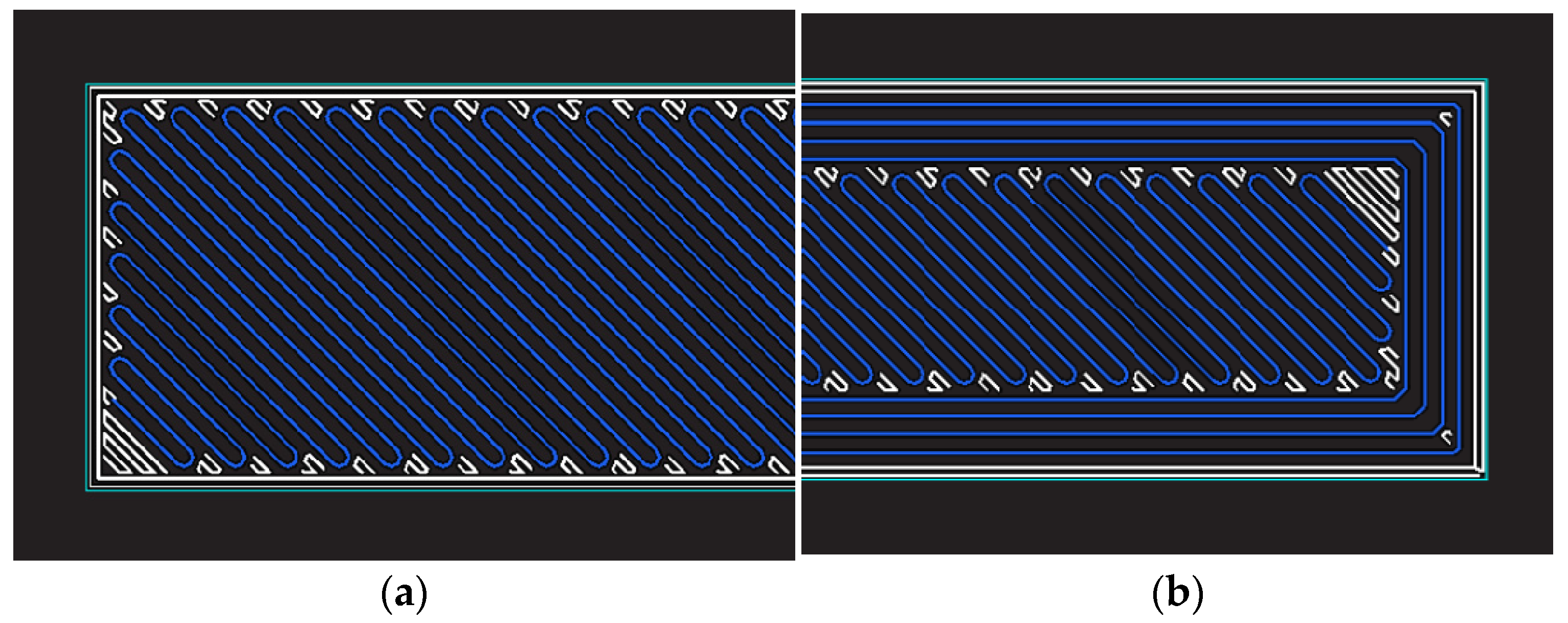
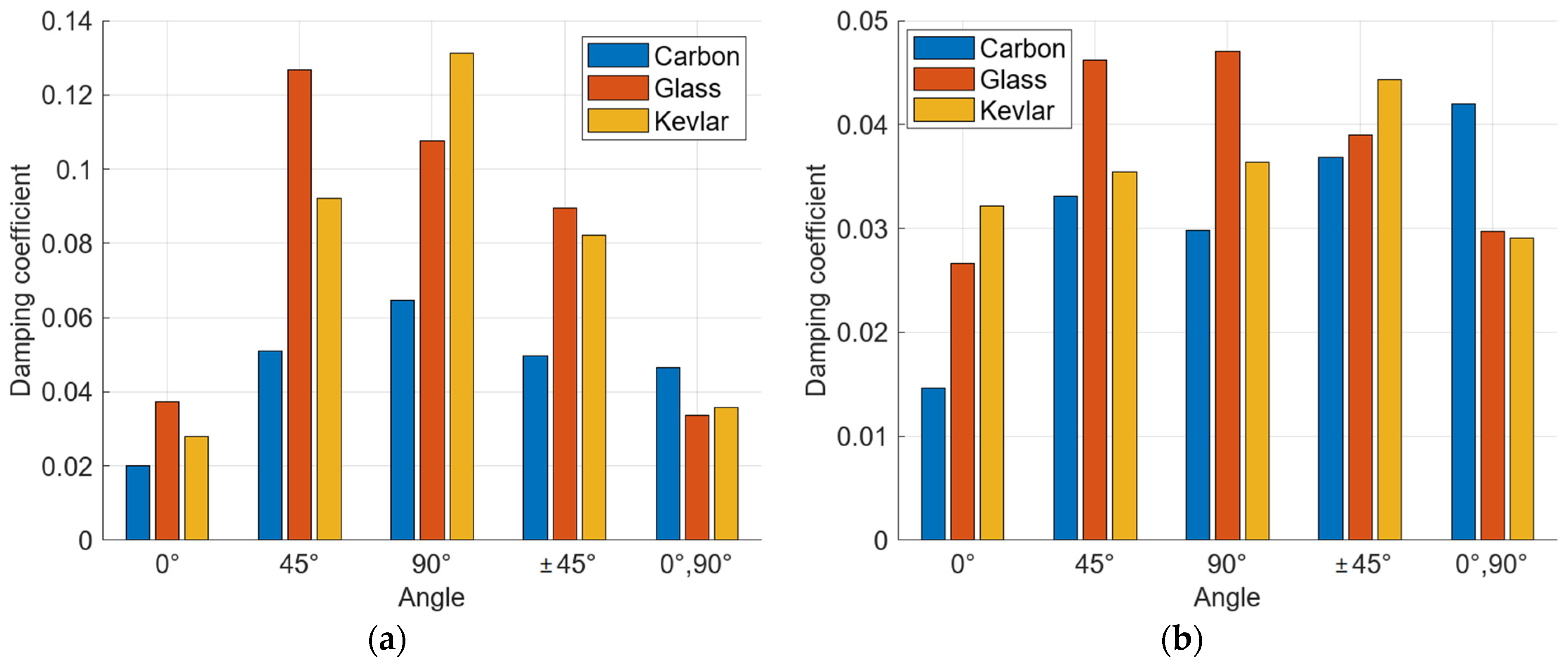
For comparison, specimens with five different configurations of reinforcement fiber orientations for three material compositions were used. The first series of specimens is reinforced with carbon fibers, the second series is reinforced with glass fibers, and the third series is reinforced with Kevlar fibers. The same fiber arrangement configurations are used in each series. The first configuration has fibers arranged longitudinally, the second configuration has fibers oriented transversely at a 45° angle to the longitudinal axis, the third configuration has fibers oriented perpendicularly, the fourth configuration has fibers oriented alternately at ±45° and the fifth configuration has fibers arranged alternately in the longitudinal and perpendicular directions.
The damping results varied depending on the examined specimen variants and their structural configurations, the type of reinforcement material used and the type of measuring equipment.
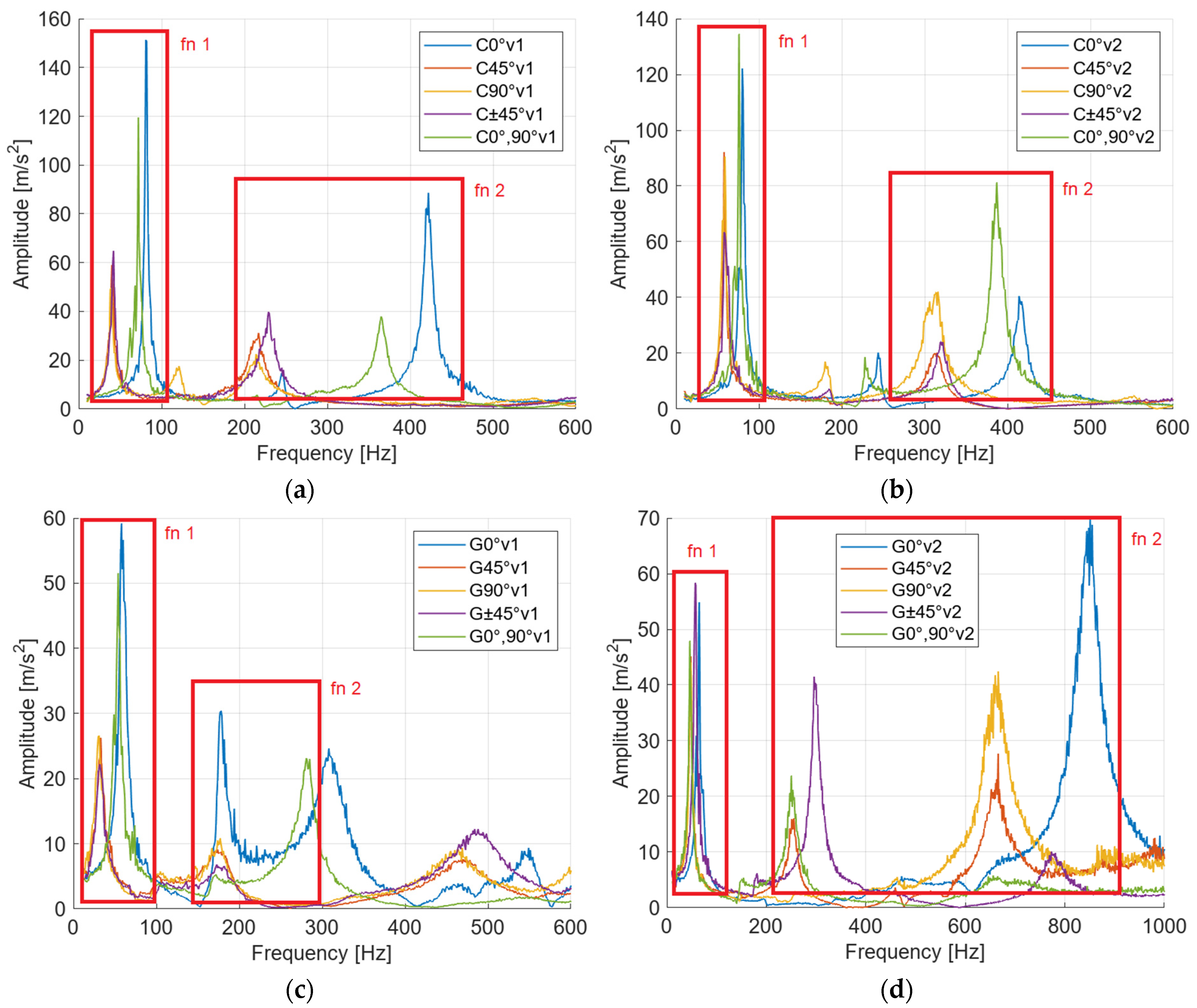
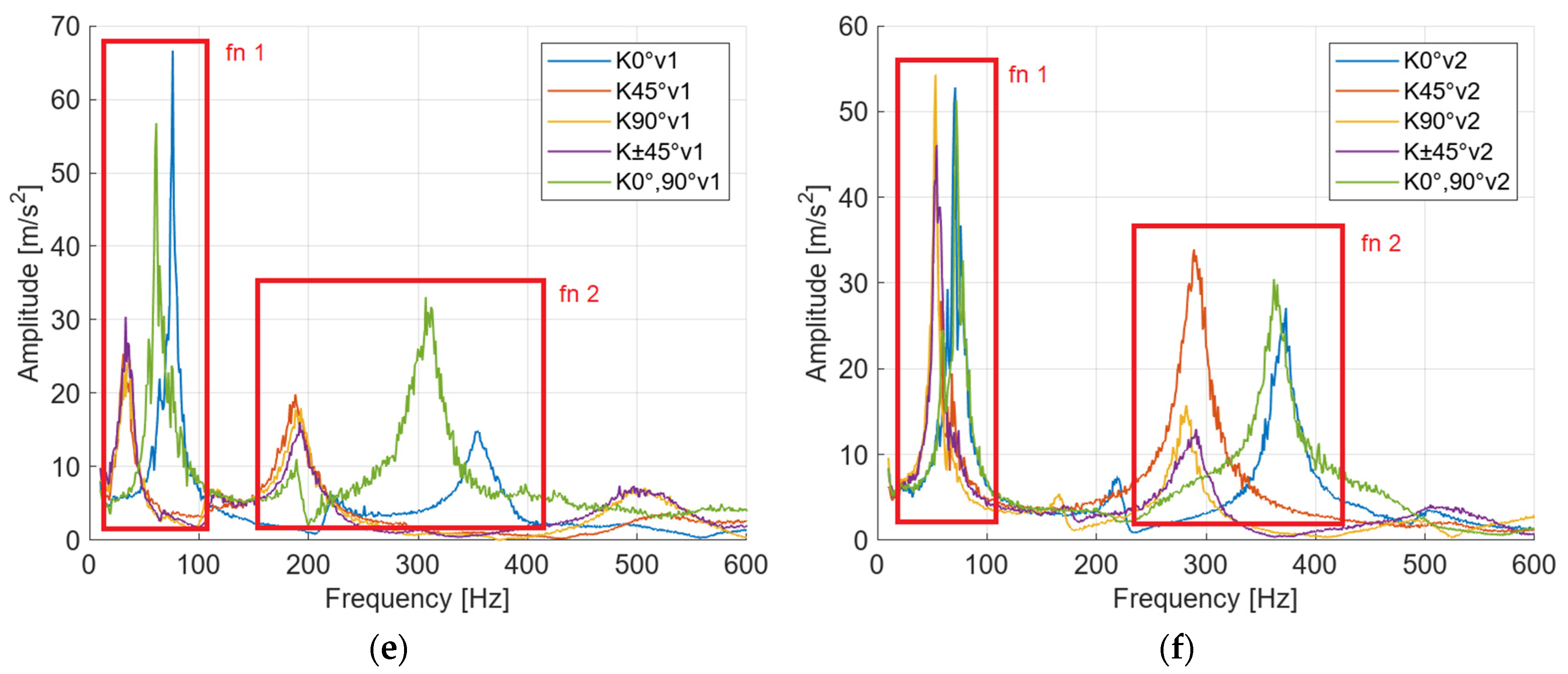
From a material perspective, the glass-reinforced specimens achieved the second highest damping values (0.232) and the lowest values were obtained by the carbon-reinforced specimens (0.087) (
Figure 5,
Figure 6 and
Figure 7). The highest damping coefficient values were achieved by the Kevlar-reinforced specimens (0.249) in the 45° configuration, except in the case of the second natural frequency of variant 1 (
Figure 6a) and variant 2 from the second workplace (
Figure 7b), where the maximum damping values were obtained by the glass-reinforced specimens.
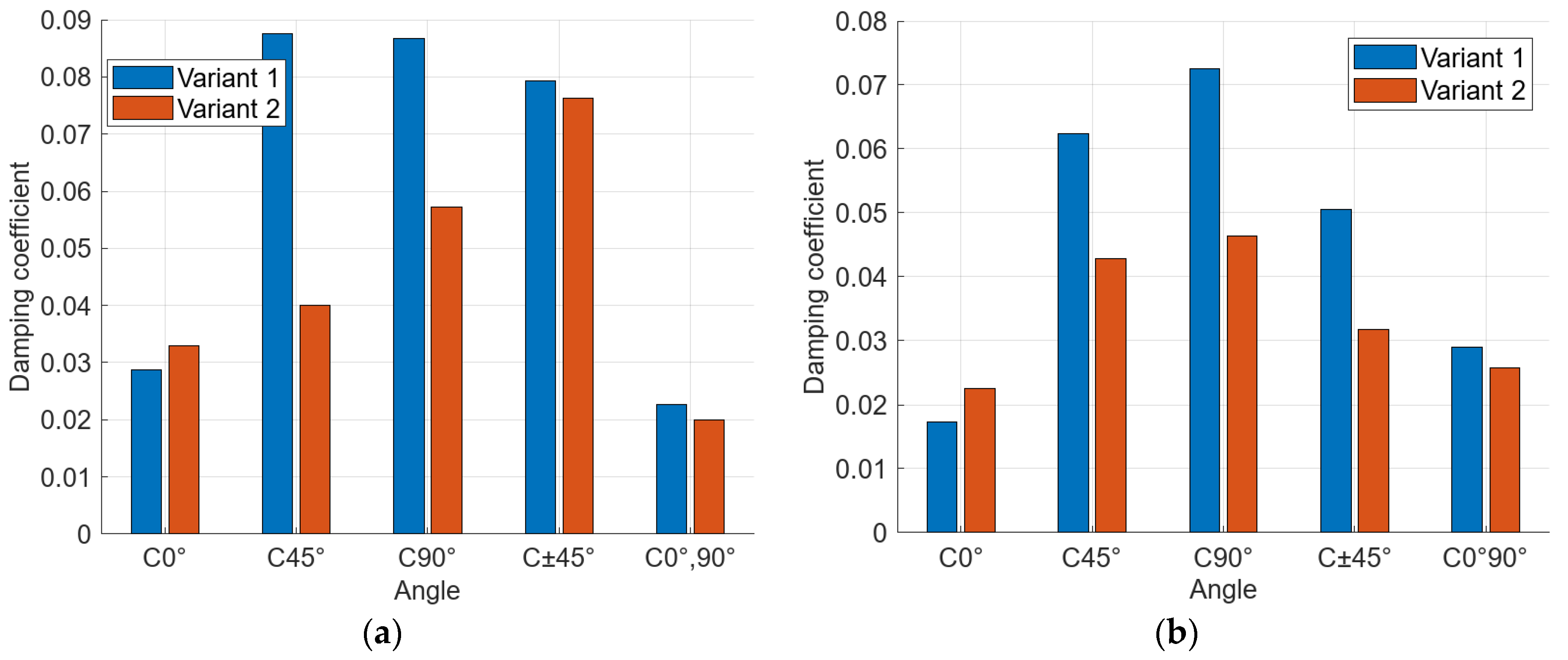
From a structural configuration perspective, the damping coefficient values for the first variant (without circumferential fibers) for the first natural frequency of the series of carbon-fiber-reinforced specimens ranged from 0.023 (5th configuration) to 0.087 (2nd configuration), representing an increase of 278%. The damping values for the second natural frequency were on average 24% lower than the damping values for the first natural frequencies. The maximum damping value in this case is, in both variants, in the 90° configuration. For variant 1, the maximum damping value is 0.073 (
Figure 6a), and for variant 2, the maximum damping value is 0.046 (
Figure 6b).
The damping coefficient values for the series of glass-fiber-reinforced specimens ranged from 0.066 (5th configuration) to 0.232 (4th configuration), representing an increase of 251%. The damping values for the second natural frequency were on average 42% lower than the damping values for the first natural frequencies. The maximum damping value in this case is in the 45° variant 1 configuration (0.134) (
Figure 6a) and in the ±45° variant 2 configuration (0.054) (
Figure 6b).
The damping coefficient values for the series of Kevlar-fiber-reinforced specimens ranged from 0.045 (1st configuration) to 0.249 (2nd configuration), representing an increase of 453%. The damping values for the second natural frequency were on average 56% lower than the damping values for the first natural frequencies. The maximum damping value in this case is in the 45° variant 1 configuration (0.09) (
Figure 6a) and in the ±45° variant 2 configuration (0.072) (
Figure 6b).
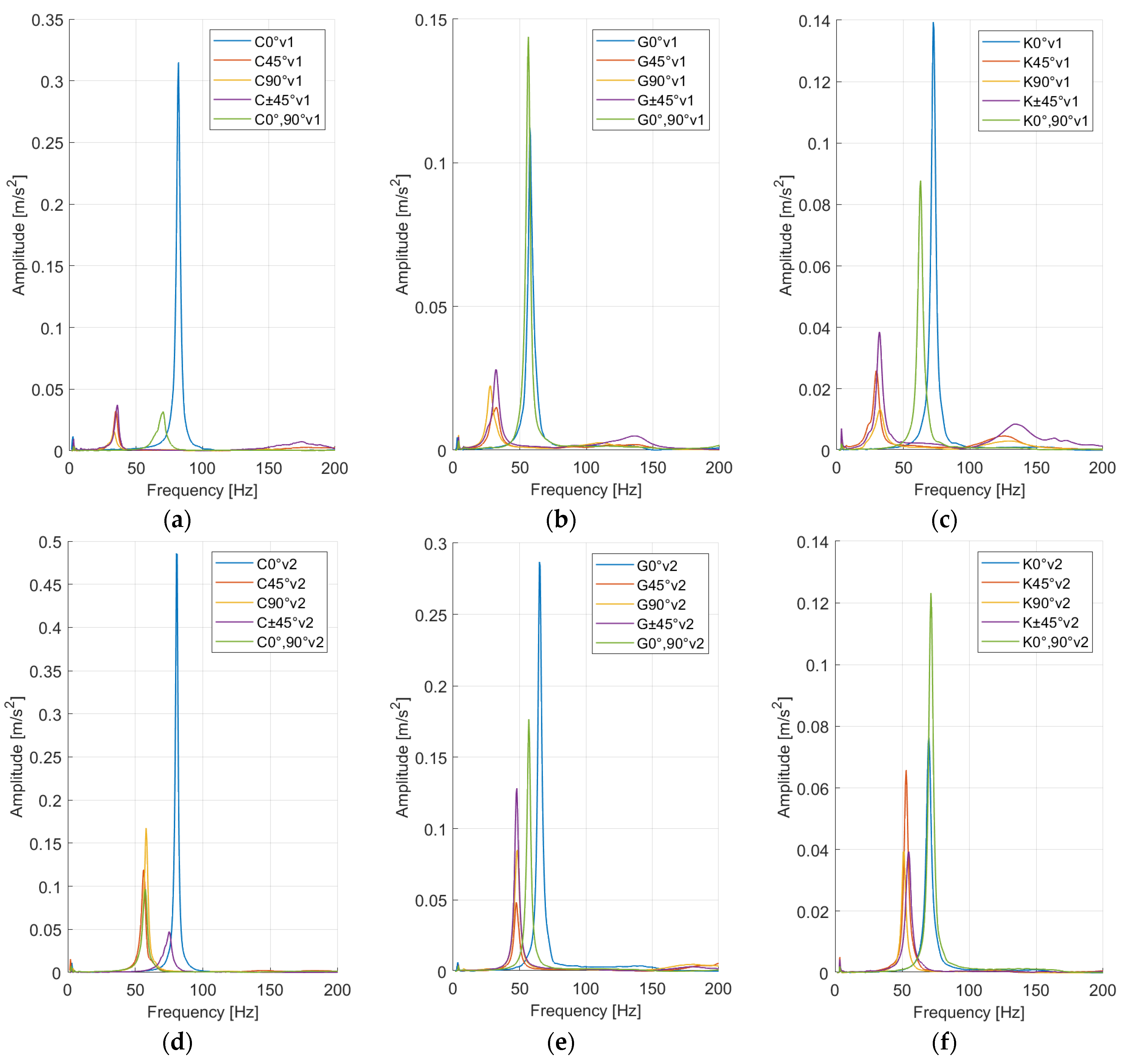
By comparing the specimens of variant 1 and variant 2, for the first natural frequency, we found that the average damping values are significantly lower in variant 2 (specimens with circumferential fibers) (
Figure 8a,c,e). For the second natural frequency, the difference in values is smaller, but there is still a significant decrease in damping in the second variant (
Figure 8b,d,f). Carbon-fiber-reinforced specimens have on average 28% lower damping values in variant 2, glass-fiber-reinforced specimens have 51% lower values and Kevlar-reinforced specimens have 48% lower values compared to variant 1 (without circumferential fibers).
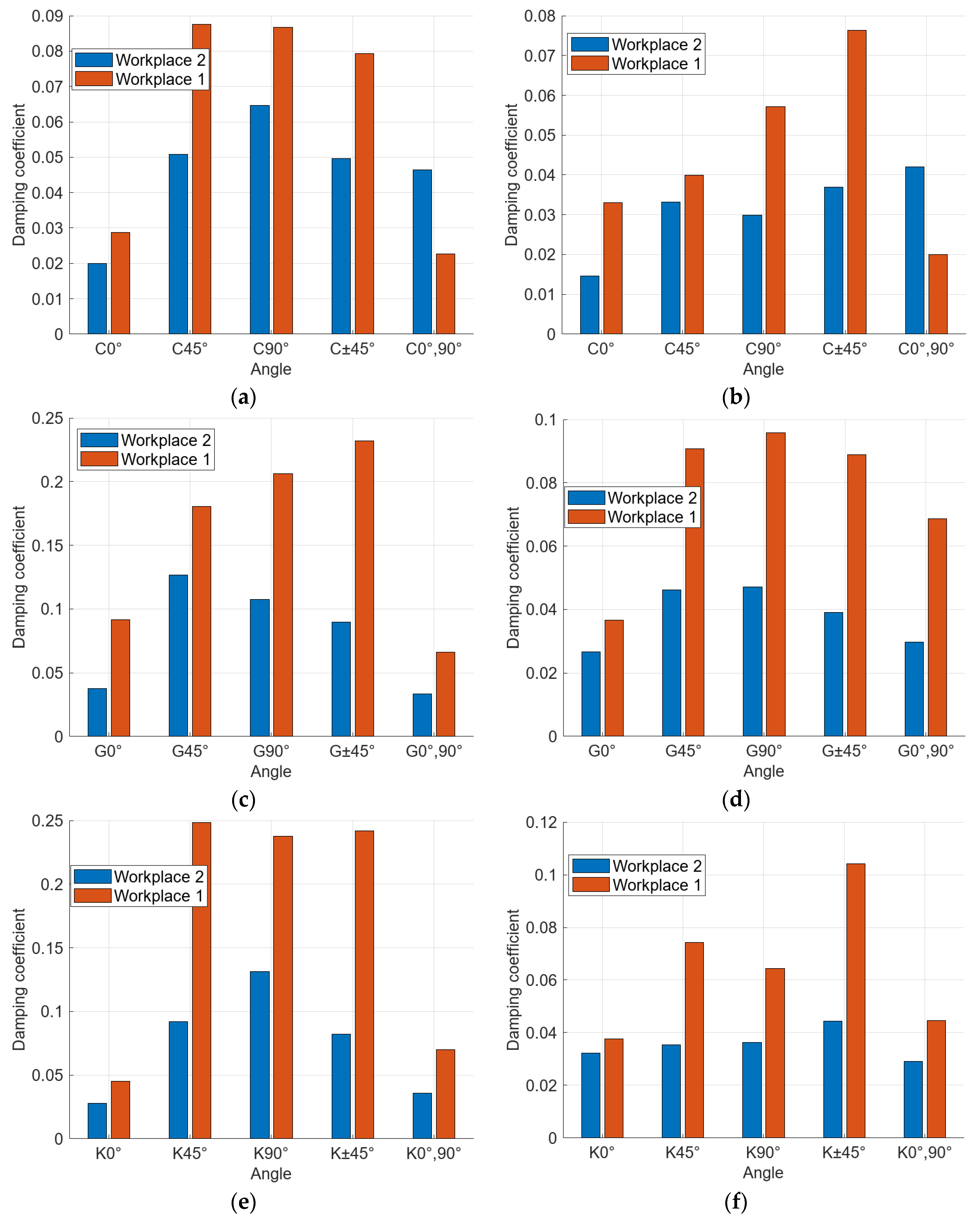
At the second workplace, the measuring devices indicated lower damping coefficient values for all materials and configurations, except for one case. In the carbon fiber reinforced specimens with the 5th configuration (
Figure 9a,b), we observed higher damping in both variants (with and without circumferential fibers). In other cases, the damping trends relative to individual configurations were similar to those observed in the measurements from the first workplace (
Figure 9). This means that the lowest damping values are in configurations 1 and 5, i.e., specimens with longitudinal fibers. In the other configurations, we observed significantly higher values.
The percentage differences in values between the workplaces are as follows. For specimens with carbon fiber reinforcement, the values from workplace 2 are on average 27% lower, for glass fiber reinforcement the values are on average 50% lower and for Kevlar reinforcement, the values are on average 51% lower than the values obtained from the first workplace. These discrepancies can be mainly attributed to the different weights of the accelerometers, as the weight ratio of the accelerometer to the specimen has a significant impact on the resonant frequencies according to findings in the paper by Drvárová et al. [
22]. The specific damping coefficient values for each specimen are shown in
Table 3 and
Table 4.
From the analysis results of the first natural frequency, it can be concluded that the lowest damping values are achieved with fiber orientations of 0° and 0°,90° for all three materials. For carbon- and Kevlar-reinforced specimens, the maximum damping values are achieved with a fiber orientation of 45° and for glass-fiber-reinforced specimens, the maximum damping is at a fiber orientation of ±45°. Furthermore, the experiment indicates that the presence of longitudinally oriented fibers significantly reduces the ability to damp vibrations. This is also evidenced by the results of variant 2 specimens (with circumferential fibers), where almost all cases showed lower damping values compared to variant 1 (
Figure 8).
The damping values expressed from the second natural frequency show lower values compared to those derived from the first natural frequency. This observation suggests that the specimens exhibit a viscoelastic damping model, which is frequency dependent. Additionally, an interface damping model is also observed, which is dependent on the fiber orientation. These damping models are more pronounced in specimens reinforced with glass and Kevlar fibers, while in carbon-fiber-reinforced specimens the changes in damping are less evident, whether depending on fiber orientation, frequency dependence or the presence of circumferential fibers.
Calculation of Mechanical Properties
The analytical calculation of the mechanical properties is based on the values of the first natural frequency. To calculate the stiffness of each specimen, we used relation (7). For the calculation of elastic modulus, we used the derived relation for the calculation of the first natural frequency of the free-loaded beam (Equations (8) and (9)).
where
k is the stiffness of the sample,
m is the mass of the sample and
ω is the natural circular frequency.
where
f1 is the first natural frequency,
λ1 is the eigenvalue for the beam with free ends,
L is the length of the beam,
E is the flexural modulus of elasticity,
I is the quadratic moment,
ρ is the density of the specimen and
A is the cross-sectional area of the specimen [
23].
All stiffness and modulus of elasticity values are shown in
Table 5 and
Table 6.
The highest values of stiffness and modulus of elasticity are achieved by the specimens with the least damping, i.e., the specimens with fiber configuration 0° and 0°,90°. The carbon fiber reinforced specimen in configuration 1 of variant 2 has the maximum flexural modulus (12.07 GPa). Conversely, the Kevlar-fiber-reinforced specimen in configuration 2 of variant 1 has the lowest modulus of elasticity (1.62 GPa).
6. Discussion
These findings have significant implications for engineering applications involving composite materials. By understanding how the arrangement of internal reinforcement affects internal damping, engineers and designers can optimize the design and performance of composite structures. This knowledge can lead to the development of more efficient and reliable mechanical components and systems across various fields of engineering, from aerospace to the automotive industry. For example, when designing composite parts where both strength and high vibration-damping capability are important, it may not be suitable in some cases to use a 0°,90° fiber orientation, since this configuration has lower damping capabilities. The study by Michal (2023) indicates that such a structure has a higher probability of fiber damage under stress [
24]. A more suitable solution might be to use a fiber orientation of 90° or ±45°, where the probability of fiber damage is lower and the damping capability is significantly higher.
To gain a deeper understanding of the impact of internal reinforcement arrangement on the internal damping of composite materials, it is essential to delve into the mechanisms that govern energy dissipation in the material. One of the critical factors to consider is the interphase bonding between the reinforcement fibers and the matrix material. The quality and strength of this bonding interface can significantly influence the material’s ability to dissipate energy through internal damping mechanisms. Future research efforts could focus on elucidating the correlation between interphase bonding characteristics and the internal damping exhibited by composite materials with different reinforcement arrangements.
Understanding how different reinforcement materials interact with the matrix and contribute to energy dissipation can pave the way for the development of composite materials with tailored damping properties suited to specific engineering applications. Therefore, it is essential to continue broadening the scope of research to include a diverse range of reinforcement materials. Investigating the internal damping behavior of composites reinforced with materials such as glass fibers, aramid fibers or even natural fibers like bamboo or jute could reveal unique damping properties, thereby enabling the advantages of composite materials to be utilized in new fields.
7. Conclusions
The article examined the impact of changes in the internal structure of composite specimens on their damping capabilities. It is important to acknowledge that the experimental methods used provide only indicative values; however, they offer advantages such as speed, simplicity and the ability to perform measurements in almost any environment. To ensure more accurate results, it is preferable to use non-contact vibration sensing, which eliminates errors caused by the mass of physical sensors. Despite differences in results from various facilities, similar conclusions can be drawn that correlate with findings from other researchers.
Our measurements indicate that the orientation of reinforcement fibers significantly affects the damping and mechanical properties. The main finding is that specimens with circumferential fibers, or the presence of longitudinal fibers combined with different fiber orientations in the center of the specimen, significantly reduced the damping of the structure. From a material point of view, the glass- and Kevlar-fiber-reinforced specimens show better damping capabilities compared to the carbon-fiber-reinforced specimens but, on the contrary, the mechanical properties are lower.


