Article

Security Performance Analysis of Full-Duplex UAV Assisted Relay System Based on SWIPT Technology

School of Electronics and Information Engineering, Liaoning University of Technology, Jinzhou 121001, China
*
Author to whom correspondence should be addressed.
Appl. Sci. 2024, 14(12), 4987; https://doi.org/10.3390/app14124987
Submission received: 30 April 2024 / Revised: 1 June 2024 / Accepted: 3 June 2024 / Published: 7 June 2024
(This article belongs to the Section Electrical, Electronics and Communications Engineering)

Abstract

:
In this paper, a new methodology is developed for modeling and analyzing a full-duplex UAV-assisted relay system to facilitate solving the problems of UAV energy constraints and the vulnerability of UAVs to eavesdropping in the air. Combining simultaneous wireless information and power transfer (SWIPT) technology, we model the downlink UAV eavesdropping channel and propose a secure transmission protocol for a full-duplex UAV-assisted relay system. Using this transmission protocol, we analyze and derive the connectivity and security of the entire communication link, including connection probability and lower bounds on secrecy outage probability. A key intermediate step in our analysis is to derive the signal-to-digital noise ratio of the destination and eavesdropping nodes of the full-duplex UAV relay link. The analyses show that the power allocation factor λ is a trade-off between system connectivity and security, while greater eavesdropping interference needs to be sacrificed for an equal magnitude of security performance improvement under high security demand conditions.

1. Introduction

In recent years, UAVs have been widely used in the military, agriculture, monitoring and prediction, transportation and logistics, and disaster rescue [1,2,3,4,5] because of their advantages, such as high mobility and low-cost networking. UAV signal transmission has line-of-sight link transmission and broadcasting characteristics, which will make the UAV communication system easier to eavesdrop on, therefore, how to guarantee the security of signal transmission has gradually become a hot issue in the study of UAV communication [6]. Compared to traditional network layer encryption techniques, physical layer security techniques have attracted a lot of attention in the field of wireless communications because they reduce the high complexity of the system and solve the problem of limited resources [7].
The combination of UAV communication and physical layer security techniques has led to a wider field of research, while UAUs play more roles in the application process. In literature [8], UAU acts as a receiver to receive signals in the presence of randomly distributed eavesdropper scenarios. In the literature [9], the UAV is used as a transmitter, and the proposed algorithm shows better convergence speed as well as good throughput by optimizing the UAV trajectory design scheme. In literature [10], the UAV acts as a jammer, moves along with the eavesdropper, and transmits a jamming signal to the eavesdropper when it reaches the optimal position, ensuring the reachable security rate of the system by reducing the eavesdropping channel capacity.
It is also possible to combine multiple uses of UAVs in the design of communication systems. For example, in the literature [11], the UAV acts as both a jammer and a transmitter, sending signals to the base station while sending jamming to the eavesdropper, maximizing the Expected Sum Rate (ESR) by optimizing the position and target rate of the UAV. When the UAV works in full-duplex mode, it can act as a transmitter and a receiver at the same time [12,13,14], which can effectively improve the spectral efficiency of the communication system. In the literature [12], the authors combine the full-duplex technique with Reconfigurable Intelligent Surface (RIS) technique and propose a joint optimization algorithm, which improves the overall secrecy rate of the UAV system. Literature [13] introduces Non-Orthogonal Multiple Access (NOMA) technique and Idle Energy Access Point (EAP) and constructs a full duplex UAV relay system. The proposed model and strategy outperform the traditional maximum-minimum relay selection scheme in terms of throughput gain. The literature [14] considers Artificial Noise (AN)-enhanced covert wireless communication in UAV networks. In the article, the UAV uses a full duplex mode of operation and sends interference to the monitor while receiving signals, and the results show that the proposed scheme significantly enhances the covert transmission performance of the system compared to the interference-free scheme.
Since the small size of the UAV leads to less energy storage, the energy limitation problem of the UAV has also attracted extensive attention from scholars. SWIPT technology was first proposed by Varshney in 2008 [15], which is a combination of signaling and energy harvesting technologies to draw energy from the received radio frequency (RF) signals. This technique is widely used in communication systems [16] and has been applied in UAV communication systems to alleviate the energy constraints of UAVs. Based on SWIPT technology and noise interference technology in the literature [17], the authors propose a new UAV-assisted relay security transmission protocol, and compared with the traditional terrestrial relay transmission protocol, the proposed protocol enhances the security performance of the system. Aiming at the scenario of a relay UAV with limited energy and active attack by full-duplex eavesdroppers, in the literature [
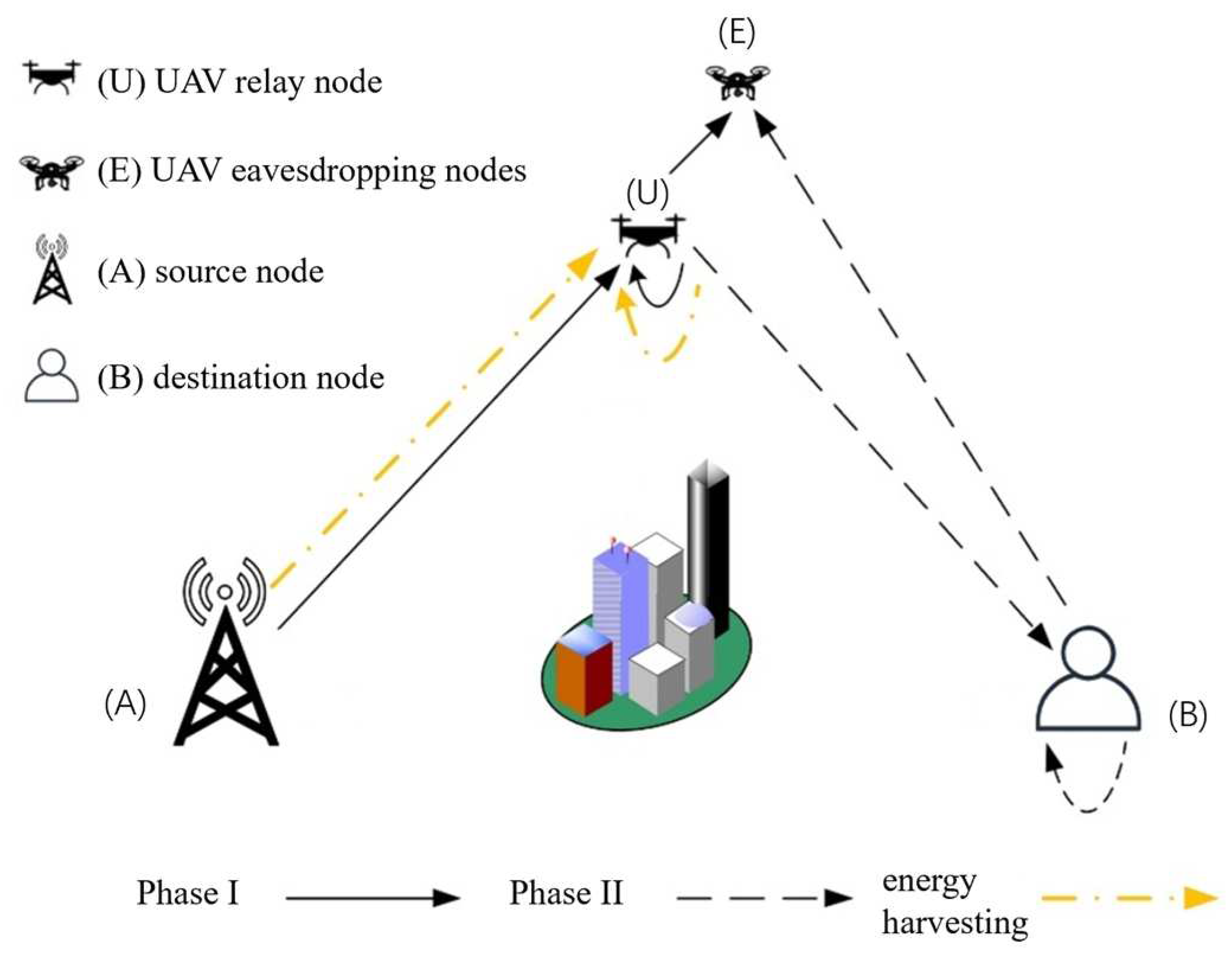
18], the authors propose a model of UAV wireless power supply technology based on SWIPT technology and analyze the impact of factors such as the base station’s transmit power, the energy harvesting time factor, and the environment on the security performance of the UAV communication system. In the existing literature, the physical layer security research of UAV relay systems by combining SWIPT technology and full-duplex technology is limited, and the research for the airborne UAV eavesdropping scenario still needs to be explored. Therefore, to address the above problems, firstly, this paper establishes a UAV downlink communication system model under an airborne eavesdropping scenario; then, it proposes a secure transmission protocol for a full-duplex UAV relay system based on SWIPT technology; then, it analyzes and derives the connection probability and secrecy outage probability of the downlink transmission; and finally, it explores the influence of system parameters such as environmental parameters, UAV altitude, energy allocation efficiency, power allocation factor, and other system parameters on the safety performance of the UAV system.

2. System Models and Transmission Protocols

2.1. System Model

This paper proposes a secure transmission model for a UAV full-duplex relay communication system based on an aerial eavesdropping scenario, which is shown in Figure 1, where all the nodes are fixed points and the source node is set as A, the destination node is set as B, the UAV trustworthy relay node is set as U, and the UAV eavesdropping node is set as E. Passive eavesdropping is adopted. Assuming that the source node A and the UAV eavesdropping node E are single antenna nodes and the UAV relay node U and the destination node D are multi-antenna nodes, the node U utilizes its own battery energy storage to control hovering and sends noise to the eavesdropping node. The UAV relay node U adopts the Amplify-and-Forward (AF) protocol and the power splitting-based relaying (PSR) strategy, and the full-duplex UAV relay communication process is divided into two phases. In the first phase, the UAV relay node U adopts the full-duplex mode of operation to receive signals from the source node A and send interference to the UAV eavesdropping node E while using the SWIPT technique to collect energy; in the second phase, the destination node B adopts the full-duplex mode and sends noise interference to node E while receiving the signal from node U. A three-dimensional Cartesian coordinate system is established for the system model, then the coordinates of the four nodes A, B, U and E are: W A = x A , y A , 0 , W B = x B , y B , 0 , W U = x U , y U , H 1 , W E = x E , y E , H 2 , Where H 1 is the height of the UAV relay node U and H 2 is the height of the UAV eavesdropping node E.
The communication links of the UAV relay system consider both large-scale fading and small-scale fading, and because the air-ground links are in the line-of-sight propagation mode, the Rician model is used to describe the small-scale fading for all air-ground links. Considering channel reciprocity, the normalized channel power gain is expressed as: S i j h i j 2 , i j a u , u b , u e , b e . Both node U and node B operate in full duplex mode, considering that the existing self-interference cancellation techniques do not completely eliminate the self-interference signals; therefore, it is assumed that the self-interference channel fading of node U and node B are f u and f B , which are the residual self-interference cancellation channels after the actual isolation and cancellation techniques, and the normalized channel power gains are S u f u 2 and S B f B 2 , respectively. In this paper, the antenna isolation method in passive interference suppression is used. This method reduces the power of the self-interference signal by increasing the distance between the transmitting antenna and the receiving antenna, which makes the self-interference cancellation performance better. At this time, the self-interference gains can be as low as 0.235 [19].
Considering the line-of-sight link signal transmission condition, the probability density function (PDF) and cumulative distribution function (CDF) of Rician fading are expressed as:
f i j x = K i j + 1 · e x p K i j + 1 x K i j · I 0 2 K i j K i j + 1 x
F i j x = 1 Q 2 K i j , 2 1 + K i j x
where i j a u , u b , u e , b e , x is an arbitrary non-negative number, I 0 · denotes the first type of zero−order corrected Bessel function and Q · , · is the first type of Marcu−Q function. The unit of K i j is dB and the expression [17] for K i j is:
K i j θ i j = k m + k M k m 2 θ i j π
where k m and k M are constants, determined by the environmental parameters and transmission rate, and θ i j 180 π a r c s i n H d i j is the elevation angle between the two nodes in radians. When θ i j is 0, it indicates that the two nodes are located in the same horizontal plane, and when θ i j converges infinitely to π 2 , it indicates that the two nodes converge to the same vertical plane. d i j is the Euclidean distance between any two points, d i j = W i W j . Considering the hindered LOS model, the path loss (PL) component related to the elevation angle is used [20]:
α i j θ i j = α L α N 1 + ω 1 · e x p ω 2 θ i j ω 1 + α N
where α L and α N denote the PL indices of the LOS link and NLOS link between two nodes, respectively. ω 1 and ω 2 are constants that change according to the specific application environment. When the signal transmitted by node i reaches the receiver of the node through the intermediate wireless medium, the large-scale fading is expressed as L i j d i j α i j , and the elevation angle between the nodes, the height of the UAV, and the environmental factors all affect the large-scale fading. The large-scale fading problem is neglected when node U and node B receive self-interfering signals in full-duplex mode.

2.2. Transmission Protocols

In the UAV eavesdropping scenario, a secure transmission protocol for the communication system is proposed. This protocol is based on SWIPT technology (the SWIPT technique follows the nonlinear RF to DC conversion model in practice [21], but a nonlinear model in this model would make the system performance analysis too complicated, so in this paper the SWIPT technique is treated according to the linear DC conversion model) and adopts PSR policy and AF protocol to realize the secure transmission of full-duplex relay communication system for UAV. Assuming that the total time slot length of the entire a full-duplex relay transmission is T, dividing T into two distinct phases, with both the first and second phase transmission times being T 2 (as shown in Table 1), β is the power splitting ratio 0 β 1 , which denotes the proportion of the transmitting power that is used for energy harvesting, and 1 β denotes the proportion used to process the received signal.
The first stage consists of signal transmission and energy harvesting processes:
The received signal y u of the UAV relay node U is:
y u = 1 β P a L a u · h a u · x a u + 1 β P u · f u · x u e + 1 β · n u + n p
where x a u is the useful signal sent by node U to node A, x u e denotes the interference signal sent by node U to node E and also the self-interference signal received by node U (This interference is assumed to be Gaussian white noise), E x a u 2 = E x u e 2 = 1 , n p is the signal processing noise under the power splitting component with power N p and n u is the channel impairments caused by the thermal noise at the UAV relay node U, which was simulated as additive complex Gaussian white noise, n u ~ C N 0 , N 0 . P a is the transmit power of the source node A in the first stage, P u is the interference noise power sent by the drone relay node U to the drone eavesdropping node E in the first stage, therefore, the total transmit power in the first stage is P = P a + P u . λ is the power allocation factor 0 < λ 1 , P a = λ P , P u = 1 λ P . When λ = 1 , the UAV relay node U does not send jamming signals to the eavesdropping node E in the first stage, and only works as a receiver.
The drone eavesdropping node E intercepts the signal sent by node A and also receives the jamming signal sent by the drone relay node U. Therefore, the received signal from node E is:
y E = P a L a e · h a e · x a u + P u L u e · h u e · x u e + n e
where n e is the additive complex Gaussian white noise received by node E, n e ~ C N 0 , N 0 .
The energy collected by the UAV relay node U comes from the signal sent by the source node A and the jamming signal sent by itself to the eavesdropping node E. The energy gained by node U is:
E = η β P a L a u S a u + P u S u + N 0 · T 2
where η is the power conversion efficiency factor.
In the second phase, the power of the node U to send a signal to the destination node B is derived from the energy captured in the first phase, and the sending power is denoted as:
P u b = E T / 2 = η β P a L a u S a u + P u S u + N 0
The signal sent by node U to destination node B is denoted as:
x u b = G · y u
where G is the amplification factor, is:
G = P u b 1 β · ( P a L a u S a u + P u S u + N 0 ) + N p
The second stage of the signal transmission process is analyzed as follows:
The destination node B receives the signal sent by the UAV relay node U and, at the same time, sends interference to the UAV eavesdropping node E. The node B is also affected by the self-interference signal:
y b = L u b · h u b · x u b + P b · f b · x b e + n b         = G 1 β P a L a u L u b · h a u · h u b · x a u + G 1 β P u L u b · h u b · f u · x u e + G 1 β L u b · h u b · n u + G L u b · h u b · n p + P b · f b · x b e + n b
where n b is the additive complex Gaussian white noise at node B, the, n b ~ C N 0 , N 0 .
The eavesdropping node E intercepts the signal x u b amplified and forwarded by node U, and also receives the jamming signal sent by node B. In this case, the signal received by node E is:
y e = L u e · h u e · x u b + P b L b e · h b e · x b e + n e         = G 1 β P a L a u L u e · h a u · h u e · x a u + G 1 β P u L u e · h u e · f u · x u e + G 1 β L u e · h u b · n u + G L u e · h u e · n p + P b L b e · h b e · x b e + n e
According to the above-proposed secure transmission protocol, the signal-to-interference plus noise ratio (SINR) of the destination node B and the drone eavesdropping node E can be obtained, and the SINR at the destination node B is:
γ A B = η β 1 β P a L a u L u b S a u S u b η β 1 β P u L u b S u b S u + η β 1 β + ξ L u b S u b N 0 + P b S b + N 0 1 β + ϵ
where ξ = N p N 0 and ϵ = N p P a L a u S a u + P u S u + N 0 .
The SINR received by the drone eavesdropping node E contains the first and second phases, which are respectively γ E 1 and γ E 2 :
γ E 1 = P a L a e S a e P u L u e S u e + N 0
γ E 2 = η β 1 β P a L a u L u b S a u S u b η β 1 β P u L u e S u e S u + η β 1 β + ξ L u e S u e N 0 + P b L b e S b e + N 0 1 β + ϵ
Since there is information eavesdropping in both the first and second phases, considering the worst-case scenario, node E applies the Maximum Ratio Combining (MRC) strategy to the received two-phase signals to process the intercepted confidential messages [15], and therefore, the SINR received by node E is γ E = γ E 1 + γ E 2 . Where γ E 1 and γ E 2 are given by Equations (14) and (15).

3. Performance Analysis

It is assumed that the channel coefficients remain constant for all nodes during each communication frame. For computational simplicity, the connection probability (CP) and secrecy outage probability (SOP) of the UAV-assisted relay system are derived for the airborne eavesdropping scenario, assuming that the system operates under medium- to high-SINR conditions. For simplicity of calculation, it is assumed that ϵ = 0 in Equations (13) and (15), and this assumption is valid for medium- to high-SINR conditions. According to the Shannon channel formula, the channel capacity of the legitimate channel in the system is defined as C M = 1 2 log 2 1 + γ A B and the channel capacity of the eavesdropping channel about the drone eavesdropping node E is defined as C E = 1 2 log 2 1 + γ E , where γ A B and γ E are the signal-to-interference plus noise ratios at node B and at node E in the communication system. Based on the first type of Marcu-Q and Bessel functions [22,23] and the literature [24], a series of complex calculations and simplifications are performed to finally derive closed expressions for the system’s probability of connectivity and the probability of safety interruption.

3.1. Connection Probability

For a full-duplex UAV-assisted relay system, the message in the legal channel undergoes two stages of transmission: A U B . R t * is the instantaneous information transmission rate when the condition is satisfied: The entire communication system is in a connected state when the channel capacity is C M > R t * . If C M R t * , the system is in a disconnected state. Therefore, the connection probability (PC) is defined as P c P r C M > R t . Assuming that δ t 2 2 R t 1 under the constraint of the threshold R t , the following theorem is obtained:
Theorem 1. 
Throughout the link transmission of  A U B , the UAV relay node U adopts the relaying method of Amplify-and-Forward, at this time, the connection probability closure expression of the legal channel is:
P c P r C M > R t = 2 1 + K u b · exp K a u K u b A 1 + K a u · d = 0 D u = 0 d s = 0 u r = 0 R Γ D + d D 1 2 d Γ R + r R 1 2 r K a u 2 d 1 + K a u u K u b r 1 + K u b r Γ D d + 1 Γ d + 1 · Γ 2 r + 1 Γ R r + 1 Γ u s + 1 Γ s + 1 A s · B u s · K s + r u + 1 ( 2 B ( 1 + K a u ) ( 1 + K u b ) ) · 1 + K a u B 1 + K u b s + r u + 1 2
where,  A = 1 β P u S u + N 0 1 β + ξ δ t 1 β P a L a u , B = P b S b 1 β + N 0 1 β δ t η β 1 β P a L a u L u b , D and R are integers used to control the precision, Γ · is the gamma function.
With the proposed system transmission protocol and the calculated SINR, after a series of complex calculations, we can derive a closed expression for the connectivity probability, as shown in Equation (16).
Proof of Theorem 1. 
The process is detailed in Appendix A. □

3.2. Probability of Safety Interruption

The secrecy capacity of the system is defined as the difference between the legitimate channel capacity and the eavesdropping channel capacity of the system, C s = m a x C A B C E , 0 , and R s * is the threshold of the secrecy transmission rate for the whole information transmission process. When C s > R s * , it indicates that the system is securely connected and the signal can be securely transmitted; when C s R s * , it indicates that the secure transmission is interrupted. C E is the instantaneous capacity of the eavesdropping link, C E = C A B C S , defined as C E = 1 2 l o g 2 1 + γ E . When C E greater than the rate difference R E = R t R s , the message is intercepted and the node E has access to the transmitted confidential information, again indicating an interruption of the secure transmission.
Theorem 2. 
Assuming  R e  as the threshold for secrecy transmission, let  δ e 2 2 R e 1 , the lower bound of the system’s secrecy outage probability in an aerial drone eavesdropping scenario is denoted by:
P s o p = P r C E > R E = P r γ E > δ e = P r m a x γ E 1 , γ E 2 = 1 P r γ E 1 δ e · γ E 2 δ e = 1 D e 1 · D e 2
D e 1 = P r γ E 1 δ e = 1 exp K a e K u e a 2 1 + K a e · d 1 = 0 D 1 u 1 = 0 d 1 s 1 = 0 u 1 r 1 = 0 R 1 Γ D 1 + d 1 D 1 1 2 d 1 Γ R 1 + r 1 R 1 1 2 r 1 K u e r 1 1 + K u e r 1 + 1 K a e d 1 1 + K a e u Γ D 1 d 1 + 1 Γ d 1 + 1 Γ u 1 s 1 + 1 Γ s 1 + 1 Γ 2 r 1 + 1 Γ R 1 r 1 + 1 a 2 u 1 s 1 · a 1 s 1 · 1 + K u e + 1 + K a e a 1 v · Γ v
where  a 1 = δ e P u L u e P a L a e ,  a 2 = δ e N 0 P a L a e ,  v = s 1 + r 1 + 1 .
D e 2 = P r γ E 2 δ e = 1 exp K a u K u e K b e c 3 1 + K a u · d 2 = 0 D 2 u 2 = 0 d 2 s 2 = 0 u 2 r 2 = 0 R 2 r 3 = 0 R 3 Γ D 2 + d 2 D 2 1 2 d 2 Γ D 2 d 2 + 1 Γ d 2 + 1 Γ u 2 s 2 + 1 Γ s 2 + 1 · c 1 c 2 s 2 · c 3 u 2 s 2 · Γ v 1 · K a u d 2 K u e r 2 K b e r 3 · 1 + K b e r 3 + 1 1 + K u e r 2 1 + K a u u 2 1 + K u e s 2 r 2 · Γ R 2 + r 2 R 2 1 2 r 2 Γ r 2 + 1 Γ R 2 r 2 + 1 · Γ R 3 + r 3 R 3 1 2 r 3 Γ r 3 + 1 Γ R 3 r 3 + 1 · { 1 + K b e 1 + K a u · c 1 c 2 s 2 + r 3 + 1 · Γ s 2 + r 3 + 1 + τ ( 1 + K a u ) · c 1 c 2 · 1 + K b e 1 + K a u · c 1 c 2 s 2 + r 3 + 2 · Γ s 2 + r 3 + 2 }
where c 1 = δ e P b L b e 1 β + 1 β N 0 , c 2 = η β 1 β P a L a e L u e , c 3 = δ e P u S u P a L a u + 1 β + ξ N 0 1 β P a L a u   τ = v 2 1 + K u e 1 1 .
Since m a x a , b a + b , a lower bound on the secrecy outage probability can be derived after a series of complex calculations as shown in Equations (17)–(19). Where D 1 , D 2 , R 1 , R 2 , R 3 are integers of definite precision, Γ · is the gamma function, and γ E 1 and γ E 2 are given by Equations (14) and (15).
Proof of Theorem 2. 
The process is detailed in Appendix B. □

4. Experimentation and Simulation

In this section, the impact of the established model and the proposed new transmission protocol on the security and reliability of the system is verified through simulation experiments, and the applicability of the communication system in the airborne UAV eavesdropping scenario in real scenarios is explored by analyzing the simulation results of the proposed scheme in this paper. If not specified later, the experimental parameters were set as shown in Table 2. In order not to lose the generality of the experiment, the Cartesian 3D coordinate system parameters are all normalized distances, where D x = 1 (CP* denotes the value taken in the calculation of CP, and SOP* denotes the value taken in the calculation of SOP).
Figure 2 shows the variation of CP versus total transmit power P for UAV relay node U under different self-interference channel gain conditions. It can be seen that when the total transmit power increases, the connection probability CP shows a trend of increasing and then stabilizing. This is because when the power allocation factor λ and the power splitting ratio β are certain, the total transmit power increases, so the power P A used for transmitting information in the first stage increases, and the channel capacity for effective information transmission increases; therefore, the connection probability shows an upward trend. When the total transmit power continues to increase, the channel capacity for effective information transmission tends to be close to the maximum transmission capacity, so the connection probability value of CP tends to stabilize. When the total transmit power P is certain, the CP increases as the self-interference channel gain of the UAV relay node U decreases. Because S u smaller means smaller path loss, the SINR at the destination node B increases, and the channel capacity for effective information transmission increases, so the connection probability increases and the system connectivity performance is enhanced.
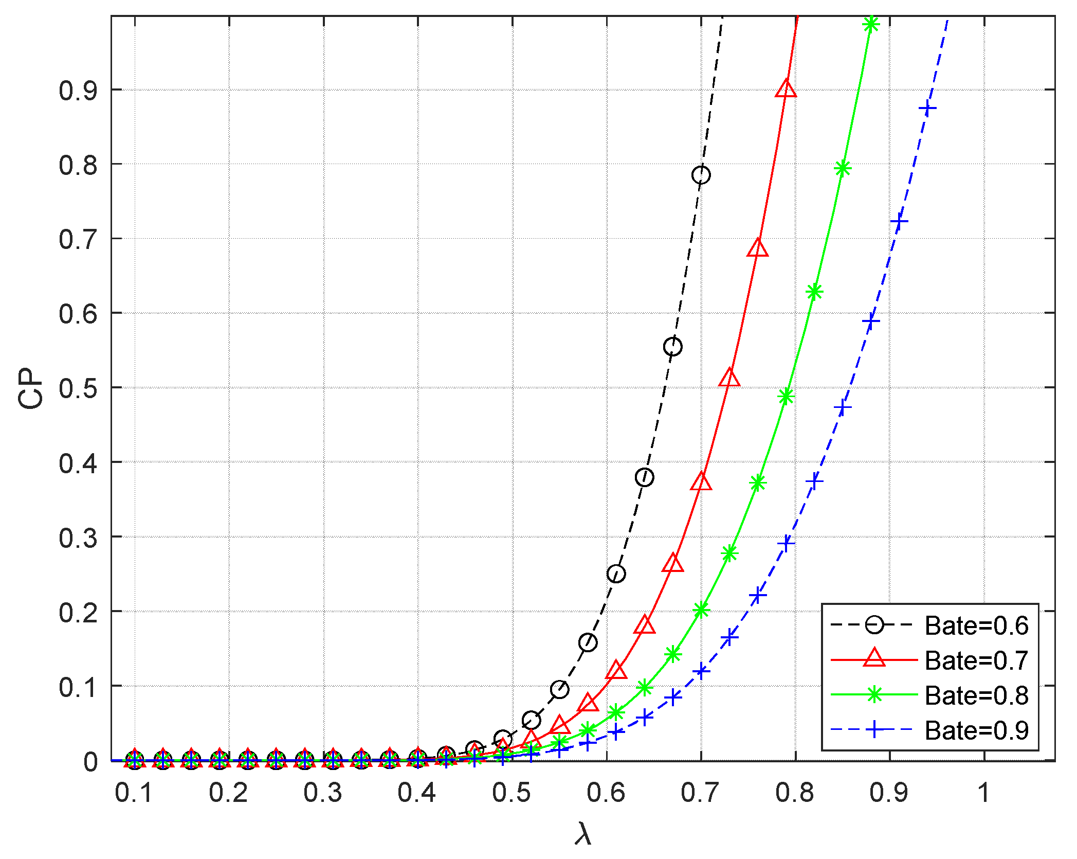
Figure 3 gives the variation of CP with respect to the power allocation factor λ for different power splitting ratios β . As can be seen from the figure, CP tends to be close to 0 when the power allocation factor λ is small, and CP increases as λ increases. An increase in λ means that the more power P A is used to transmit information in the first stage, therefore, the channel capacity for effective information transmission increases, which confirms the correctness of the conclusions of Figure 2. When the power splitting ratio β is certain, there exists a system connection initiation value λ * . When λ < λ * , the power allocated to the signal transmission is not enough to transmit a valid signal, at this time the system is in the unconnected state; when λ λ * , the system can only be in the connected state. From the figure, it can be seen that when the other condition parameters are certain, the larger the value of power splitting ratio β is taken, the larger the value of system connection initiation λ * is. When the power splitting ratio β decreases from 0.9 to 0.6 at a certain value of λ , the power used for energy harvesting decreases while the power used for the first stage of signal processing increases, and therefore the connection probability is enhanced.
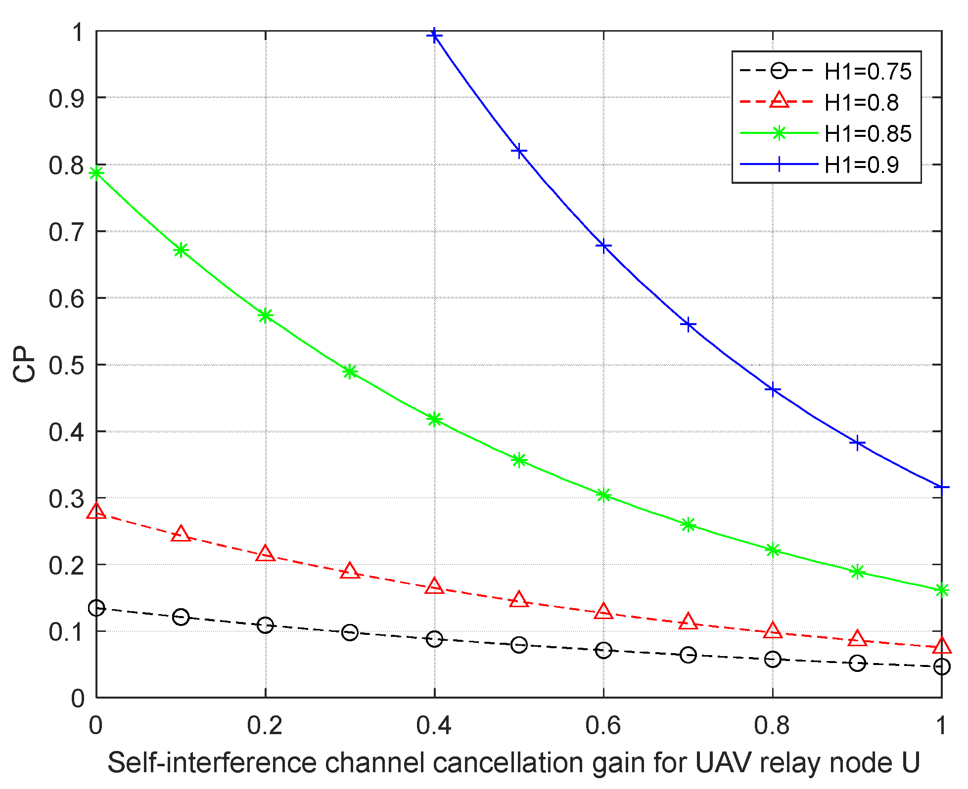
Figure 4 investigates the variation relationship between connection probability CP and UAV self-interference gain S u under different flight altitudes of UAV relay node U. From the figure, it can be seen that when S u increasing, CP decreases, and the higher the height H 1 of UAV relay node U, the greater the decreasing trend of CP; when S u is certain, the higher the normalized height of UAV relay node U, the greater the CP. When H 1 increasing from 0.75 to 0.9, the line-of-sight channel link for effective information transmission is enhanced and the probability of transmission of LOS increases, and therefore, the probability of connectivity CP increases.
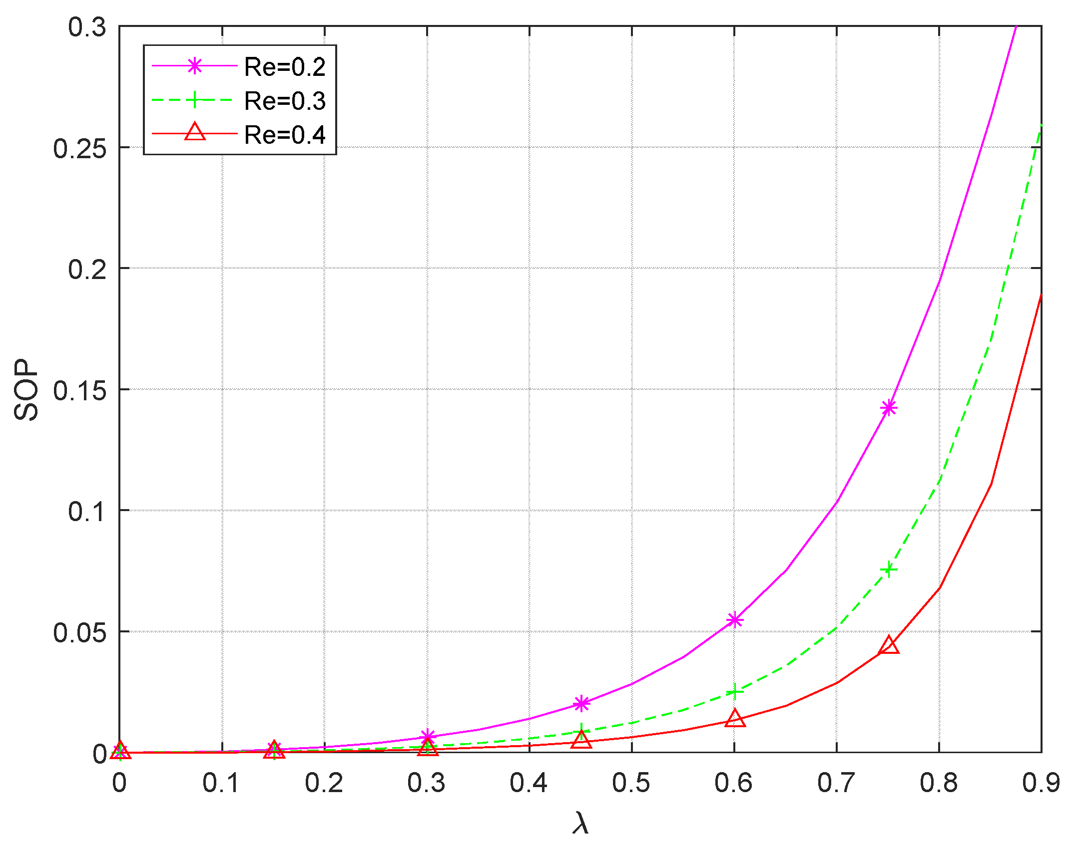
Figure 5 reveals the relationship between SOP and power allocation factor λ under different eavesdropping rate thresholds R E . As can be seen from the figure, when the total transmit power P is certain, the SOP increases with the increase of λ . This is because an increase in λ for a certain P leads to an increase in P A and a decrease in the power P U used to send the jamming signal to the UAV eavesdropping node E. This causes the channel capacity of the eavesdropping link to become larger, at which point the information is more likely to be eavesdropped and the secrecy outage probability SOP increases. The smaller the power allocation factor λ is, the better the secure transmission of the system is, but the security of the system is limited by the system connectivity. From the conclusion of Figure 1, it can be seen that the system can only be connected when λ λ * , and the larger the λ is, the better the connectivity is, so there is a trade-off between the system’s connectivity and security. In addition, when λ is certain, the SOP decreases as the eavesdropping rate threshold R E increases, and the smaller the threshold R E the greater the change in the value of the power allocation factor λ is required when raising the same value of the security interruption probability. This suggests that when security needs are high, increasing security by an equal margin comes at a greater cost in terms of eavesdropping interference.
Plot (a) in Figure 6 compares the effect of different environmental parameters on the secrecy outage probability SOP. The (b) plot in Figure 6 is a localized enlargement of the (a) plot, where A takes values from 0.58 to 0.62. When the environmental parameters ω 1 = 4.88 , ω 2 = 0.43 , it corresponds to a suburban environment; when the environmental parameters ω 1 = 9.61 , ω 2 = 0.1 , the environment is urban; when the environment is a dense urban area, the environmental parameters ω 1 = 12.08 , ω 2 = 0.11 ; when the environment is a high-rise building, the environmental parameters ω 1 = 27.23 , ω 2 = 0.08 . From the (b) graph in Figure 6, it can be seen that the system’s secrecy outage probability is minimized in the environment of a high-rise city. This is because in the environment of high-rise buildings, the fading of the system will increase, but at this time, the interference signal sent by the UAV relay node U to the UAV eavesdropping node E belongs to the high-altitude transmission, which is less affected, so the eavesdropping channel capacity will become smaller, the SOP of the system decreases, and the security of the system is enhanced.
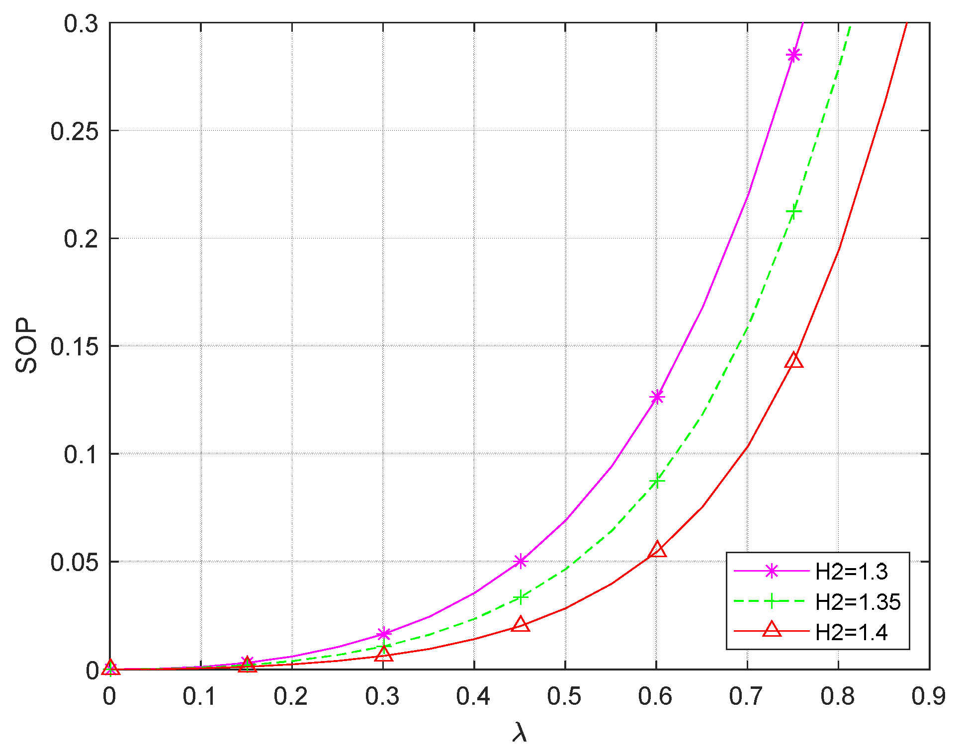
From Figure 7, it can be seen that when the H 1 normalized height is 1, the SOP of the system decreases as the height of the eavesdropping UAV increases from 1.3 to 1.4, causing an increase in the security performance of the system. This is because when the eavesdropping UAV height H 2 increases, the probability of line-of-sight propagation of the eavesdropping signal transmission increases, and at the same time, the eavesdropping interference decreases, which reduces the security performance of the system. But if it continues to increase H 2 , it will lead to a higher path loss, which will cause a reduction in the channel capacity of the system’s eavesdropping channel link, and the security performance of the system will be enhanced.
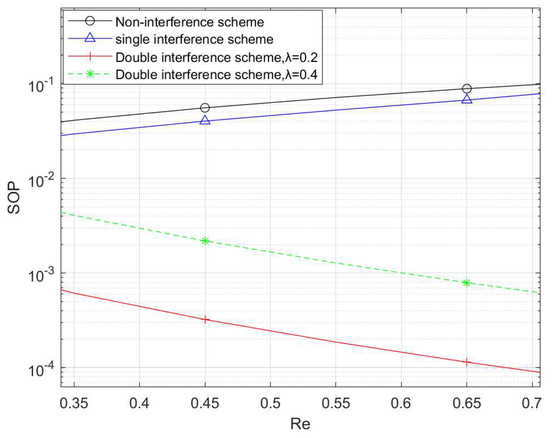
Figure 8 compares the variation of SOP with the eavesdropping rate threshold R e for different eavesdropping interference schemes. Scenario 1 is a no interference scenario, where there is no interference signal in the first and second phases of the whole communication system; Scenario 2 is a single interference scenario, where only the destination node sends interference in the second phase; and Scenario 3 is the double interference scenario proposed in this paper, where the relay UAV U is in full-duplex mode and there are eavesdropping interferences in both the first and second phases of the relay communication link. From the figure, it can be seen that the size relationship of secrecy outage probability under different eavesdropping interference schemes is: double interference scheme < single interference scheme < no interference scheme, so the relationship of system security performance is double interference scheme > single interference scheme > no interference scheme. For the dual interference scheme proposed in this paper, as λ decreases, for example, A changes from 0.4 to 0.2, the SOP decreases. This is because when the total transmit power is certain, the decrease in λ implies that the jamming signals acting on the eavesdropping node increase; therefore, the SOP of the whole communication link decreases, and the security performance of the system is enhanced, which verifies the relationship between the SOP and λ once again. The results show that the proposed scheme in this paper outperforms the half-duplex UAV scheme as well as the non-interference scheme in terms of security performance.

5. Conclusions

In this paper, a communication system model of a full-duplex UAV-assisted relay based on SWIPT technology is established for the airborne UAV eavesdropping scenario. A new secure transmission protocol is proposed according to the model, and the lower bound analytic closure expressions for the connection probability and secrecy outage probability of the downlink transmission are derived. The effects of power splitting ratio, power allocation factor, self-interference channel gain, and UAV flight altitude on the performance of the system are derived from the experimental simulation, which provides a reference for the model design of the actual scenario.

Author Contributions

Conceptualization, S.Y.; methodology, S.Y.; software, S.Y.; validation, S.Y.; formal analysis, S.Y.; investigation, S.Y.; resources, S.Y.; data curation, S.Y.; writing—original draft preparation, S.Y. and H.M.; writing—review and editing, S.Y. and H.M.; visualization, S.Y. and H.M.; supervision, H.M.; project administration, H.M.; funding acquisition, H.M. All authors have read and agreed to the published version of the manuscript.

Funding

This work is supported by the Liaoning Provincial Education Department Fund (LJKZ0624, JYTZD2023083, LJKFZ20220238, LJKMZ20220965).

Institutional Review Board Statement

Not applicable.

Informed Consent Statement

Not applicable.

Data Availability Statement

The original contributions presented in the study are included in the article, further inquiries can be directed to the corresponding author/s.

Conflicts of Interest

The authors declare no conflicts of interests.

Appendix A

Connection Probability (CP) Derivation Procedure:
Assuming that X = S a u , Y = S u b ,
P c P r C M > R t = P r γ A B > δ t = P r η β 1 β P a L a u L u b X Y η β 1 β P u L u b Y S u + η β 1 β + ξ L u b Y N 0 + P b S b + N 0 1 β > δ t
assuming that
A = 1 β P u S u + N 0 1 β + ξ δ t 1 β P a L a u
B = P b S b 1 β + N 0 1 β δ t η β 1 β P a L a u L u b
Since the nodes A and U are Rice fading between them, the calculations are based on the PDF and CDF of the Rice distribution, which leads to Equations (A4).
P c = P r X > A + B Y = 1 E Y F X | Y A + B Y = 0 Q 2 K a u , 2 1 + K a u A + B y · 1 + K u b · e K u b · e x p 1 + K u b y · I 0 2 K u b K u b + 1 y d y
where, Q · , · is a first-order Marcu-Q function and I 0 · is a first-order modified Bessel function of order 0.
I 0 y = r = 0 R Γ R + r R r 2 r Γ 2 r + 1 Γ R r + 1 y 2 2 r
Q x , y = d = 0 D u = 0 d Γ D + d D 1 2 d x 2 d y 2 u Γ D d + 1 d ! u ! 2 d + u e x 2 + y 2 2
Substituting Equations (A5) and (A6) into Equation (A4) the simplification leads to:
P c 1 + K u b · exp K a u K u b A 1 + K a u · d = 0 D u = 0 d s = 0 u r = 0 R Γ D + d D 1 2 d Γ R + r R 1 2 r K a u d 1 + K a u u K u b r 1 + K u b r Γ D d + 1 Γ d + 1 · Γ 2 r + 1 Γ R r + 1 Γ u s + 1 Γ s + 1 A s · B u s · 0 e x p ( 1 + K a u ) B y ( 1 + K u b ) y ) y s + r u d y
According to the formula equation (Equation (3.471.9) [24]), the integral of Equation (A7) is calculated, and the final closed expression for the connection probability is obtained after complex calculations, which is represented by Equation (16).

Appendix B

Safety Outage Probability (SOP) Derivation Procedure:
From Equation (17), the derivation of P s o p requires the separate computation of the two parts D e 1 and D e 2 , so:
P s o p = 1 D e 1 · D e 2
Defining V = S a e , W = S u e , it follows:
D e 1 = P r P a L a e V P u L u e W + N 0 δ e = P r V δ e P u L u e P a L a e W + δ e N 0 P a L a e = E w { F v w ( δ e P u L u e P a L a e w + δ e N 0 P a L a e ) }
Defining a 1 = δ e P u L u e P a L a e , a 2 = δ e N 0 P a L a e , Equation (A9) reduces to:
D e 1 = E w F v w a 1 w + a 2 = 0 F a e a 1 w + a 2 f u e w d w = 0 1 Q 2 K a e , 2 ( 1 + K a e ) ( a 1 w + a 2 ) f u e ( w ) d w = 0 f u e ( w ) d w 0 Q 2 K a e , 2 ( 1 + K a e ) ( a 1 w + a 2 ) f u e ( w ) d w
Since the derivation of Equation (A10) is similar to that of Theorem 1, the derivation will not be repeated, and the expression for D e 1 is finally obtained according to (Equation (3.481.4) [24]) and is given in Equation (18), where v = s 1 + r 1 + 1 .
Since X = S a u , W = S u e , here Z = S b e is defined, and the expression (15) for γ E 2 is obtained by substituting it into Equation (19):
D e 2 = P r γ E 2 δ e = P r X δ e P u S u P a L a u + N 0 1 β + ξ δ e 1 β P a L a u + δ e P b L b e Z + N 0 δ e η β P a L a u L u e W
Defining c 1 = δ e P b L b e , c 2 = N 0 δ e , c 3 = η β P a L a u L u e , c 4 = δ e P u S u P a L a u + 1 β + ξ N 0 1 β P a L a u , Equation (A11) is further simplified to obtain:
D e 2 = E z E w z F x | w , z c 1 z + c 2 c 3 w + c 4 = 1 0 ψ x ( z ) f z ( z ) d z
where ψ x ( z ) is represented by Equation (A13).
ψ x ( z ) = 0 Q ( 2 K a u , 2 1 + K a u c 1 z + c 2 c 3 w + c 4 f w ( w ) d w = d 2 = 0 D 2 u 2 = 0 d 2 s 2 = 0 u 2 s 3 = 0 s 2 Γ D 2 + d 2 D 2 1 2 d 2 Γ D 2 d 2 + 1 Γ d 2 + 1 · Γ u 2 s 2 + 1 Γ s 2 s 3 + 1 Γ s 3 + 1 · e x p K a u K u e 1 + K a u c 4 · c 1 s 3 c 2 s 2 s 3 c 3 s 2 c 4 u 2 s 2 · 0 w s 2 · e x p ( 1 + K u e ) w ( 1 + K a u ) c 1 z + c 2 c 3 w w 1 · I 0 ( 2 K u e ( K u e + 1 ) w ) d w
Let the integral in Equation (A13) be D D , and Equation (A14) is obtained by simplification according to the Taylor series formula and the equation (Equation (3.381.4) [24]).
D D = 0 w s 2 · e x p 1 + K u e w 1 + K a u c 1 z + c 2 c 3 w w 1 · I 0 2 K u e K u e + 1 w d w = r 2 = 0 R 2 Γ R 2 + r 2 R 2 1 r 2 · K u e r 2 ( 1 + K u e r 2 ) r 2 · e Ω Γ 2 r 2 + 1 Γ R 2 r 2 + 1 [ ( 1 Ω ) ( 1 + K u e ) v 1 Γ ( v 1 ) + Ω ( 1 + K u e ) v 2 · Γ ( v 2 ) ]
where Ω = ( 1 + K a u ) ( c 1 c 3 z + c 2 c 3 ) .
Substituting Equations (A13) and (A14) into Equation (A12) and further simplifying according to equation (Equation (3.381.4) [24]), the final expression for SOP can be obtained as shown in Equation (17). Where τ = ( v 1 + 1 ) 1 + K u e 1 1 , v 1 = 1 + r 2 s 2 .

References

  1. Zaharia, S.M.; Pascariu, I.S.; Chicos, L.A.; Buican, G.R.; Pop, M.A.; Lancea, C.; Stamate, V.M. Material Extrusion Additive Manufacturing of the Composite UAV Used for Search-and-Rescue Missions. Drones 2023, 7, 602. [Google Scholar] [CrossRef]
  2. Ma, J.; Chen, P.; Wang, L. A Comparison of Different Data Fusion Strategies’ Effects on Maize Leaf Area Index Prediction Using Multisource Data from Unmanned Aerial Vehicles (UAVs). Drones 2023, 7, 605. [Google Scholar] [CrossRef]
  3. Song, C.; Wang, Q.; Wang, G.; Liu, L.; Zhang, T.; Han, J.; Lan, Y. Study on the Design and Experiment of Trichogramma Ball Delivery System Based on Agricultural Drone. Drones 2023, 7, 632. [Google Scholar] [CrossRef]
  4. Shen, H.; Wang, T.; Heng, Y.; Bai, G. Joint Resource Slicing and Vehicle Association for Drone-Assisted Vehicular Networks. Drones 2023, 7, 534. [Google Scholar] [CrossRef]
  5. Chen, X.Y.; Sheng, M.; Li, B.; Zhao, N. An overview of 6G-oriented UAV communications. J. Electron. Inf. 2022, 44, 781–789. [Google Scholar]
  6. Zeng, Y.; Zhang, R.; Lim, T.J. Wireless communications with unmanned aerial vehicles: Opportunities and challenges. IEEE Commun. Mag. 2016, 54, 36–42. [Google Scholar] [CrossRef]
  7. Dong, R.Z.; Wang, B.H.; Feng, D.G.; Cao, K.R.; Tian, J.W.; Cheng, T.H.; Diao, D.Y. Secure Transmission Techniques for Physical Layer of UAV Communication Networks. J. Electron. Inf. 2022, 44, 803–814. [Google Scholar]
  8. Wang, D. A Theoretical Study of Physical Layer Security for Unmanned Aircraft Communication Systems. Master’s Thesis, Chongqing Post and Communications University, Chongqing, China, 2020. [Google Scholar]
  9. Wu, Q.; Zeng, Y.; Zhang, R. Joint trajectory and communication design for multi-UAV enabled wireless networks. IEEE Trans. Wirel. Commun. 2018, 17, 2109–2121. [Google Scholar] [CrossRef]
  10. Gao, Y.; Tan, R.J.; Deng, Z.X. Confidentiality performance optimization under UAV-assisted physical layer security. J. Electron. Inf. 2022, 44, 2730–2738. [Google Scholar]
  11. Duan, Z.; Yang, X.; Zhang, T.; Wang, L. Optimal Position and Target Rate for Covert Communication in UAV-Assisted Uplink RSMA Systems. Drones 2023, 7, 237. [Google Scholar] [CrossRef]
  12. Lai, H.; Li, D.; Xu, F.; Wang, X.; Ning, J.; Hu, Y.; Duo, B. Optimization of Full-Duplex UAV Secure Communication with the Aid of RIS. Drones 2023, 7, 591. [Google Scholar] [CrossRef]
  13. Li, T.S.; Shi, A.N.; Wang, Z.; He, L. SWIPT-based throughput-optimized NOMA full-duplex relay selection strategy. Commun. Lett. 2021, 42, 87–97. [Google Scholar]
  14. Zhou, X.B.; Peng, X.; Yu, H.; Zhao, F.Y.; Wu, Q.Q. Artificial Noise Enhanced Short Packet Covert Communication in UAV Networks. J. Signal Process. 2022, 38, 1601–1609. [Google Scholar]
  15. Varshney, L.R. Transporting information and energy simultaneously. In Proceedings of the 2008 IEEE International Symposium on Information Theory, Toronto, ON, Canada, 6–11 July 2008; pp. 1612–1616. [Google Scholar]
  16. Krikidis, I.; Timotheou, S.; Nikolaou, S.; Zheng, G.; Ng, D.W.; Schober, R. Simultaneous wireless information and power transfer in modern communication systems. IEEE Commun. Mag. 2014, 52, 104–110. [Google Scholar] [CrossRef]
  17. Mamaghani, M.T.; Hong, Y. On the performance of low-altitude UAV-enabled secure AF relaying with cooperative jamming and SWIPT. IEEE Access 2019, 7, 153060–153073. [Google Scholar] [CrossRef]
  18. Yan, Y.F.; Zhang, S.W. Energy Efficiency Study of SWIPT-Based Full-Duplex Trunking Collaboration System. J. Nanjing Univ. Posts Telecommun. (Nat. Sci. Ed.) 2019, 39, 55–62. [Google Scholar]
  19. Zeng, Y.; Zhang, R. Full-duplex wireless-powered relay with self-energy recycling. IEEE Wirel. Commun. Lett. 2015, 4, 201–204. [Google Scholar] [CrossRef]
  20. Azari, M.M.; Rosas, F.; Chen, K.C.; Pollin, S. Ultra reliable UAV communication using altitude and cooperation diversity. IEEE Trans. Commun. 2017, 66, 330–344. [Google Scholar] [CrossRef]
  21. Boshkovska, E.; Ng, D.W.K.; Zlatanov, N.; Schober, R. Practical non-linear energy harvesting model and resource allocation for SWIPT systems. IEEE Commun. Lett. 2015, 19, 2082–2085. [Google Scholar] [CrossRef]
  22. Sofotasios, P.C.; Freear, S. Novel expressions for the Marcum and one dimensional Q-functions. In Proceedings of the 2010 7th International Symposium on Wireless Communication Systems, York, UK, 19–22 September 2010; pp. 736–740. [Google Scholar]
  23. Cao, K.; Gao, X. Solutions to Generalized Integrals Involving the Generalized Marcum Q-Function with Application to Energy Detection. IEEE Commun. Lett. 2016, 20, 1780–1783. [Google Scholar] [CrossRef]
  24. Gradshteyn, I.S.; Ryzhik, I.M. Table of Integrals, Series, and Products; Academic Press: Cambridge, MA, USA, 2014. [Google Scholar]
Figure 1. Full-duplex UAV relay communication system based on airborne UAV eavesdropping scenario.
Applsci 14 04987 g001
Figure 2. CP vs. total transmit power P for different UAV node U self-interference channel gain conditions.
Applsci 14 04987 g002
Figure 3. CP vs. power allocation factor λ for different power splitting ratio β conditions.
Applsci 14 04987 g003
Figure 4. Relationship between CP and UAV self-interference gain S u under different flight altitude conditions at UAV relay node U.
Applsci 14 04987 g004
Figure 5. SOP versus power allocation factor λ for different eavesdropping transmission rate thresholds R E .
Applsci 14 04987 g005
Figure 6. Relationship between SOP and power allocation factor under different environmental parameter conditions.
Applsci 14 04987 g006
Figure 7. SOP vs. power allocation factor for different eavesdropping UAV altitudes H 2 .
Applsci 14 04987 g007
Figure 8. Relationship between eavesdropping thresholds and SOPs under different scenarios.
Applsci 14 04987 g008
Table 1. PS-based secure transmission protocol.
Transmission ProcessPhase I: 0 ~ T 2 Phase II: T 2 ~ T
signal transmissionA → U (Effective signal transmission)
U → E (Sending Interference Noise)
U → U (Self-interference)
U → B (relay amplification and forwarding)
B → E (Sending Interference Noise)
B → B (Self-interference)
energy harvestingA → U (SWIPT)
U → U (SWIPT)
not have
Table 2. Simulation parameters.
ParametricSimulation Value
W A 0,0 , 0
W B D x , 0,0
H 1 1
H 2 1.4
W U 0.3 D x , 0 , H 1 (CP*)
0.8 D x , 0.8 , H 1 (SOP*)
W E 0.4 D x , 0 , H 2 (CP*)
0.4 D x , 0.4 , H 2 (SOP*)
Environmental parameters: ω 1 4.88 (CP*)
27.27 (SOP*)
Environmental parameters: ω 2 0.48 (CP*)
0.08 (SOP*)
Self-interference channel power gain at destination node B: S B 0.1 (CP*)
0.2 (SOP*)
Self-interference channel power gain for UAV U: S u 0.5
Path loss index: α L 2
Path loss index: α N 3.5
network transmission rate: R t (bps/Hz)0.5
eavesdrop transmission rate: R E (bps/Hz)0.2
noise power: N 0 (dBm)10
k m 1
k M 10
p o w e r d i s t r i b u t i o n f a c t o r : λ 0.7
power split ratio: β 0.4
Power conversion efficiency factor: η 0.9
noise-to-power ratio: ξ 5
Total Transmit Power: P (W)150
Noise transmission power at destination node B: P B (W)100
Disclaimer/Publisher’s Note: The statements, opinions and data contained in all publications are solely those of the individual author(s) and contributor(s) and not of MDPI and/or the editor(s). MDPI and/or the editor(s) disclaim responsibility for any injury to people or property resulting from any ideas, methods, instructions or products referred to in the content.

