Abstract
An uplink multi-user tracking problem aided by multiple passive reconfigurable intelligent surfaces (RISs) is addressed in this work. Under a near-field circumstance, a multi-antenna base station (BS) localizes multiple moving single-antenna users by processing the received signals transmitted by users and reflected by RISs. Considering the users’ mobility and the potential obstruction of line-of-sight paths, a multi-user tracking system based on the extended Kalman filter (EKF) which fully exploits the temporal correlations between each user’s coordinate changes is designed. Then, the Bayesian Cramér–Rao bound (BCRB) of tracking errors is derived in a pattern consistent with the EKF process. Subsequently, an optimization scheme for passive phase shift design at the RISs is devised by minimizing the derived BCRB and is solved using the Gradient Descent method. Numerical results indicate that the accuracy of our tracking algorithm can approach the BCRB. With abundant RISs deployed and optimized, high-precision multi-user tracking via a single BS can be realized even in harsh localization environments.
1. Introduction
High-precision positioning, as an essential concern in sensing, holds great promise for future sixth-generation (6G) mobile networks, encompassing various applications such as augmented reality, Internet of Vehicles, virtual reality, and unmanned aerial vehicle communications [1,2,3]. As carrier frequencies move toward millimetre waves (mmWaves) and higher sub-THz spectrum, large antenna arrays enabling high sensing resolution can be widely used, making radio-based high-precision positioning from signals possible [1,2,3,4]. Typical radio localizing methods consist of measuring received signal strength (RSS), angle of arrival (AOA), angle of departure (AOD), time of arrival (TOA), and time difference of arrival (TDOA) of incident signals from multiple base stations (BSs) [5,6,7,8,9].
According to the electromagnetic (EM) propagation theory, increasing the radio frequency to meet the demands of ultra-high-speed data transmission in 6G networks can significantly weaken the effects of diffraction [1,2]. Therefore, there is heavy reliance on line-of-sight (LoS) paths to guarantee satisfactory RSS and carry location information of targets. The existing methods may suffer from severe performance degradation in harsh EM environments, especially in mobile scenarios, where complex conditions such as multipath, clutter, and non-line-of-sight (NLoS) propagation frequently occur [10].
To solve the aforementioned positioning problem, reconfigurable intelligent surfaces (RISs) are introduced as energy-saving and low-cost devices [11,12,13,14]. RISs are essentially large EM meta-surfaces; each element is capable of independently adjusting the amplitude and phase of an incident radio wavefront passively, thereby enabling precise control over the reflection of the waves [15]. Once installed in wireless environments, RISs can precisely direct signals towards the desired direction, thus significantly enhancing the virtual line-of-sight (VLoS) links [11,16]. From a positioning perspective, RISs can serve as an extra reference point, offering supplementary measurements that help to avoid dependence on the LoS path [17].
Introducing RISs into positioning recently sparked widespread interest due to its promising benefits. For instance, Björnson et al. [18] analyzed a downlink orthogonal frequency division multiplexing (OFDM) scenario aided by RIS from both the communication and positioning perspectives. Similarly, Wymeersch et al. [19] derived the Cramér–Rao lower bound (CRLB) for positioning error in a downlink setting, emphasizing how deploying RIS in the far field can outperform conventional methods relying solely on naturally occurring scatterers for better positioning accuracy. Elzanaty et al. [20] explored the upper limits of positioning performance of an uplink multiple-input multiple-output (MIMO) system, proposed a near-field propagation model, and demonstrated the significant promotion of positioning accuracy brought by a single RIS. Zhang et al. [21] applied a RIS-assisted user positioning scheme based on RSS in an indoor scenario, where a high-resolution signal intensity map was built to localize the target through iterative optimization of RIS phase shift. Lin et al. [22] introduced a beam searching method based on hierarchical codebook design to achieve accurate positioning indirectly by utilizing RIS-assisted channel parameters. Similarly, the user position was estimated from the channel information of RIS, and channel angle parameters were obtained through the maximum likelihood method [23]. For MIMO-OFDM systems, He et al. [24] implemented a twin-RIS structure and applied advanced signal processing techniques to extract relevant information from the received signals. Dardari et al. [25] considered a single-anchor positioning problem under NLoS conditions characterized by frequent applications. More practical RIS-assisted localization schemes can be found in [26,27].
The design of the RIS is the most critical part of assisting either positioning or communication. Literature concerning the optimization of RIS-assisted communications under various channel state information (CSI) and a priori location knowledge is abundant [28,29,30]. However, existing optimization solutions for RIS aimed at improving communication are not necessarily practical or optimal in improving positioning. RIS optimization focusing on positioning is less frequently investigated. Lin et al. [31] proposed a new RIS conformal structure that can be used to estimate the AoD and AoA of RISs and solve scatterer and user localization problems based on it. Fascista et al. [32] studied joint positioning and synchronization problems and optimized the BS precoding and RIS phase shift based on their proposed novel beamforming codebook. Rahal et al. [33] and Gao et al. [34] optimized a RIS by minimizing positioning error bounds (PEB), where the blockage of LoS and hardware limitations were considered. Feng et al. [35] proposed an optimization scheme of RIS based on CRLB for positioning and transmit power minimization and adopted a semi-positive semi-definite relaxation method for the power minimization part.
Most existing works involving RIS-assisted localization consider snapshot localization, and only a few works address the user tracking problem. Teng et al. [36] proposed a Bayesian tracking scheme which is realized indirectly by estimating AoAs. If the user’s initial location information is known, better positioning accuracy can be achieved through directional beamforming on the BS side [32]. Furthermore, works in [37,38,39,40] resolve the problem in a double-scale way, significantly reducing the RIS reconfiguration rate. Fewer works consider multi-user tracking problems. Recently, Yu et al. [41] studied a multi-user localization problem and introduced two semi-passive RISs to estimate the AoA on the RIS; the consequent hardware overhead would be inconsistent with the low-cost intention of introducing RIS. Teng et al.proposed a multi-user tracking algorithm based on Bayesian theory, carrying out positioning by estimating AoA and optimizing passive beamforming of RIS [42]. However, the model adopted is only valid for the far-field scenario, and a two-step approach starting from intermediate parameters is suboptimal to direct means, as it demands an appropriate characterization of the measurement statistics.
Methods and types of the most relevant RIS-assisted positioning literature are listed in Table 1. With carrier frequencies moving toward mmWaves and higher sub-THz spectrum, large antenna arrays are widely used in tracking scenarios, where the targets often move in near-field regions. However, the signal model adopted in existing works is only valid for the far-field scenario. Among existing works involving RIS-assisted localization, most consider snapshot localization without exploiting the temporal correlations of user locations. In dynamic scenarios, the localization performance of these methods can be severely limited. Further, few works investigate the multi-user tracking problems in RIS-assisted systems.

Table 1.
Methods and types of the most relevant RIS-assisted positioning literature.
Enlightened by the correlated works and considering their limitations, we study an uplink multi-user tracking problem aided by multiple passive RISs under the near-field circumstance, where the BS and users are equipped with multiple antennas and a single antenna, respectively. As indicated in Figure 1, the LoS paths between the BS and users are presumed to be blocked during the tracking process. The core insights offered by this research include:
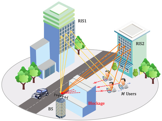
Figure 1.
RIS-aided multi-user tracking scenario.
- Considering the temporal correlations between each user’s coordinates changes, a multi-user tracking system is designed based on the extended Kalman filter (EKF), where the non-linear relationships between the signals received at the BS antennas and the coordinates of the moving users are directly utilized.
- Based on the near-field model accounting for the incident spherical wavefront, its geometric properties are further exploited. Additional measurement dimensions can be provided by the RISs to suffice high-precision multi-user tracking with a single BS, thus avoiding the reliance on the LoS paths.
- The Bayesian Cramér–Rao bound (BCRB) is derived for the multi-user tracking system in a pattern consistent with the EKF process, providing a theoretical lower bound of mean square error (MSE) for the tracking problem.
- An optimizing scheme of passive phase shift design at the RISs is devised. The issue is formatted as a problem of minimizing the derived BCRB of tracking errors and solved by leveraging the Gradient Descent (GD) method. Numerical results indicate that the accuracy of the proposed tracking scheme can approach the derived BCRB.
The remainder of the study unfolds as follows. The tracking scenario, geometry, and signal model of the proposed system are described in Section 2. The basic navigation framework, including the transition model, observation model, and proposed tracking algorithm, is elaborated in Section 3. The BCRB of the proposed RIS-aided tracking scheme and the optimization of RISs’ phase shift are presented in Section 4. A series of simulations are conducted, and the validity and accuracy of the proposed tracking system are demonstrated in Section 5. The conclusions are stated in Section 6. Additionally, notations and operators used in this work are enumerated in Table 2.
Table 2.
Notations and operators.
2. System Model
2.1. Tracking Scenario and Geometry
We set up a multi-RIS-aided localization scenario in a Cartesian coordinate system, where a multi-antenna BS localizes M moving single-antenna users by processing the received signals transmitted by users and reflected by K RISs consisting of multiple elements.
According to Figure 2, we denote as the centre of BS, as the coordinate of the b-th antenna on the BS with , as the centre of k-th RIS, as the coordinate of the p-th element on the k-th RIS with and , as the coordinate of the m-th user with . The distances between elements can be represented as , , and . The elevation and azimuth angles between two elements are and , respectively. The local reflection coefficient of an element of RIS is , where is the gain of the unit element and is the unit-norm load coefficient [25,28]. The variable set includes , and represents the normalized power radiation pattern per element, which remains constant across the frequencies of interest and is characterized in an exponential-Lambertian radiation pattern with parameter q as
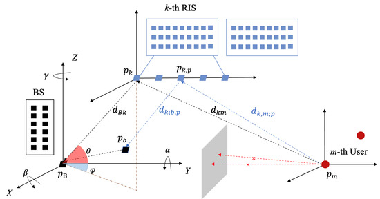
Figure 2.
Geometry of tracking system.
2.2. Signal Model for Incident Spherical Wavefronts
In the uplink, M users operate on orthogonal frequencies but share the same configurations of RISs. Given the carrier frequency , subcarrier spacing , the frequency of the m-th user can be expressed with , and the signal bandwidth is . Each user transmits a single data symbol , which meets the criteria of . The LoS paths between the BS and users are presumed to be blocked, while VLoS paths reflected by RISs always exist. The received signal from the m-th user at the BS, , is
where P denotes the transmit signal power, and are the channel matrices of BS-(k-th)RIS and (k-th)RIS-(m-th)user links, respectively. Here, we put the normalized power radiation pattern and gain of each RIS element into the channel matrices. Thus, only contains the unit-norm load coefficient of each RIS element, i.e., denotes the unit-norm load coefficient of the p-th element of the k-th RIS and . denotes the additive white Gaussian noise (AWGN) sequences with variance . BS estimates the users’ positions by exploiting the spherical waveform model. The components of the channel matrix are modelled as
where , are the attenuation due to propagation of the LoS components, and satisfies the relation of , where c is the speed of light. We adopt a simple Rice channel model to describe the links between RISs and users, and are the Ricean factors for (k-th)RIS-(m-th)user links. We assume that the LoS paths always exist, as the probability of the LoS condition is close to 1 in the near-field region [37]. denotes the random complex fading coefficients of the NLoS components. The received signal at the b-th antenna on the BS from the m-th user results in
where is the interference-plus-noise term containing the AWGN noise and the multipath components and is given by
4. RIS-Aided Tracking Error Bound and Optimization
4.1. Derivation of BCRB
The inaccuracy in modelling users’ dynamic patterns and the limitations of the adopted measurement method may bring uncertainty to the users’ state estimates. Denote the users’ estimated state as ; the MSE of the users’ state estimation satisfies
where denotes mathematical expectations for users’ states and observations; is the Bayesian Fisher information matrix (BFIM) of users’ states , which can be expressed as [43]
where and are the BFIM of the users’ a priori information [44] and the data of observations[45], respectively. Specific expressions of them are
Given initialized , the Fisher information matrix at time can be recursively calculated, and the BCRB of users’ state estimation error can be attained by
Note that should be parameterized by theoretically but may not always be available. Instead, we rely on the predictions made during the previous time interval. Since the diagonal elements of the BCRB include the lower bound of the MSE of both users’ position and velocity estimates, (26) cannot be used directly as the metric of tracking accuracy. Here, we denote
and . Thus, the metric of tracking accuracy can be prescribed as
The derived BCRB serves as a benchmark for the proposed tracking scheme, based on which an optimization scheme for the phase shift of RISs is proposed in the subsequent section.
4.2. GD-Based RIS Phase Shift Optimization
To achieve high-precision multi-user tracking, we design the phase shift induced at the RISs to minimize the BCRB mentioned above, i.e.,
where denotes the set of RISs’ reflection coefficient matrices . To tackle the optimization problem, we utilize the classical GD-based method. By applying the second-order Taylor expansion at the given point , the approximate function is given by [46]
As long as the GD updating step is chosen properly, which can be determined by the Armijo rule [47], the approximation function satisfies the following three properties[48,49]
Then, the optimal solution of at the -th iteration is given by
It is proved in [46] that the optimal follows the update rule of the GD method, which is given by
Notably, the calculation of can be converted into the gradient calculation of the phase shift of each element, which is given by [50]
the detailed derivation of which is shown in Appendix B. The corresponding update process of is given by
This procedure will repeat until it satisfies the stopping criteria. The whole procedure entailing the RISs’ phase shift design is sketched in Algorithm 2.
| Algorithm 2 Optimization for RISs’ phase shift |
| Initialization . Set iteration index .
repeat Compute and according to (19) and (28), respectively. For each element in , calculate by (34). For each element in , update by (35). Set . until the fractional decrement of the target value is below a certain threshold. Output: |
5. Results
A series of simulations are conducted in this section to assess the validity of the proposed tracking algorithm. With different parameter settings, the performance of our tracking algorithm against the BCRB is compared.
5.1. Simulation Scenario and Parameter Settings
Unless otherwise indicated, we focus on the tracking scenario as sketched in Figure 3.
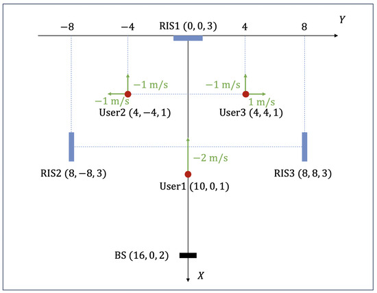
Figure 3.
The simulation scenario.
For the channel settings, we consider a simple scenario where each single-antenna user transmits a single data symbol at a unique frequency. We set carrier frequency , subcarrier spacing , the frequency of the m-th user , and the signal bandwidth . The gain of the RIS unit element , and the gain of the antenna of users and BS are and , respectively. In our tracking scheme, the LoS paths between BS and users are presumed to be blocked. The interference power caused by large-scale fading and reflection loss is weaker than the LoS path in general [51]. Thus, at the receiver, we fix the noise variance per subcarrier at , and at the transmitter, we consider that transmitted power per subcarrier P varies from to .
For system geometry, the only BS is located at , and RISs are deployed at , including , and . The BS consists of a uniform planar array of elements lying on the plane and the RISs are equipped with a uniform linear array of elements on the , , and planes, respectively. According to , the antenna spaces on the BS array and the element spaces on the RISs’ array are . Notably, the elements in RISs are mainly deployed horizontally as long stripes, by which the radiating near-field scope is extended over about .
For the kinematic model of users, single-antenna users move in a uniform linear pattern with , and . The initial positions of users are , , and , the first of which has an initial velocity of in the x direction, and the other two users both have initial velocities of in the x direction and and in the y direction, respectively. The initial state is assumed to be relatively accurately measured with minor errors generated based on randomly.
For clearer declarations, the parameter settings of simulations are given in Table 3.
Table 3.
Simulation parameter settings.
5.2. Simulation Results and Discussions
5.2.1. Convergence and Error Analysis of Tracking
We first study the convergence and error of our tracking scheme by executing a 3-second trajectory once with the experimental method and parameters in Section 5.1, which contains 100 discrete samplings of users’ positions. Other simulations conducted within the range of our parameter settings follow the same path.
The number of operations is hard to generalize as it depends on the choice of GD updating step size and other parameters. However, the convergence characteristics of the algorithm are worthy of study. As illustrated in Figure 4, this cluster of curves represents the convergence process of the optimization algorithm in 100 discrete sampling time slots, where the ordinate denotes the value of the objective function, and the abscissa denotes the number of iterations. The phase shift matrix of all RISs in each sampling time slot is randomly generated. We set the value of the objective function MSE at the end of the first tracking time slot as the metric for subsequent time slots, where the optimization procedure will repeat until it satisfies the stopping criteria. It can be found that the optimization of the phase shift design converges well, which validates the effectiveness of Algorithm 2. Further, our algorithm exploits temporal correlation and continuity during the tracking process, requiring fewer adjustments in subsequent time slots. Thus, except for the first optimization of RISs’ phase shift at the first tracking time slot, the optimization process takes much fewer operations in the subsequent time slots.
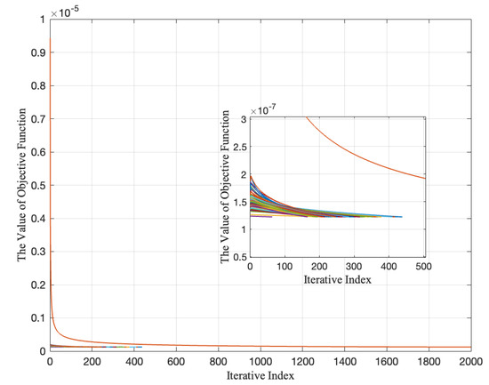
Figure 4.
The convergence of Algorithm 2. ; other parameters follow Table 3.
The accuracy of our proposed tracking scheme is evaluated by the root mean square error (RMSE) of tracking errors. As indicated in Figure 5, the abscissa denotes 100 consecutive time slots and the ordinate denotes the RMSE of the tracking errors. The RMSE of the tracking errors with random phase shift is divergent, as the LoS paths between users and the BS are presumed to be blocked, which is a relatively harsh tracking scenario. However, our tracking scheme with optimized phase shift can achieve significant accuracy and can approximate the theoretical BCRB, which validates the effectiveness of Algorithm 1. Further, in the optimized case, it can be found that at some certain sampling slots, the RMSE of tracking errors is larger than other slots. This indicates that even if our tracking scheme is temporarily underperforming, it will not cause major interference with the subsequent tracking process, since the EKF procedure is a data fusion process based on both model prediction and data measurement.
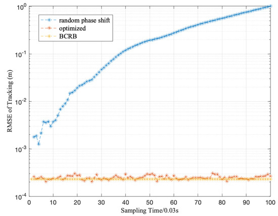
Figure 5.
The performance illustration of Algorithm 1. ; other parameters follow Table 3.
5.2.2. Effect of the Number of BS Antennas
We first investigate the effect of the number of BS antennas on the RMSE of tracking with varying transmit power. In this and all the subsequent simulations, the performance of our tracking scheme is evaluated by the RMSE of tracking errors averaging from 30 conducted 3-second trajectories, each containing 100 discrete samplings of users’ positions. The tracking error with random phase shift on RISs, the averaging of which has no practical significance, will not be further studied because it is divergent.
With other variable parameters fixed at , , , , , the transmit power P varying from to and the number of BS antennas is set by , , and as a comparison, respectively.
As illustrated in Figure 6, from three groups of simulations with different numbers of BS antennas, it is easy to find that the accuracy of our tracking algorithm can approximate the theoretical BCRB. With the increment of BS antennas, our tracking algorithm performs significantly better and approaches closer to the BCRB. This is reasonable as the increment of BS antennas extends the dimension of measurements, which contributes to the accuracy of the estimation procedure. Moreover, the performance of our tracking scheme improves and approximates BCRB more closely with the increment of transmit power.
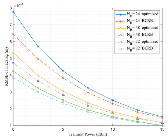
Figure 6.
Performance illustration with different numbers of BS antennas set by , , and and transmit power P varying from to . Other variable parameters are fixed at , , , , .
5.2.3. Effect of Users’ Mobility
To study the effect of the mobility of users, we have a fixed sampling frequency, which means that the localization and optimization procedure is conducted at the same time slot length. Thus, users’ mobility can be characterized by both covariance matrix . With other variable parameters fixed at , , , , the transmit power P varies from to . Controlled simulations are conducted where the velocities of users are fixed, and in vary within the range of , , and .
It is obvious in Figure 7 that the tracking of trajectories with minor covariance attains higher accuracy and can reach a relatively good accuracy even under a high-covariance circumstance. Moreover, the performance of our tracking scheme improves and approximates BCRB more closely with the increment of transmit power.
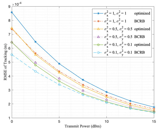
Figure 7.
Performance illustration of the effect of users’ mobility , set by , , and 1 and transmit power P varying from to . Other variable parameters are fixed at , , , .
5.2.4. Effect of the Number of RISs and RIS Elements
We exploit the influence of both the number of RISs and RIS elements.
To assess the influence of the number of RISs, with other variable parameters fixed at , , , , , the transmit power P varying from to and the RIS deployed at is removed in the case. As indicated in Figure 8, the performance of tracking in the case is significantly better than in the case. With the increment in the number of RISs, our tracking algorithm approaches much closer to the BCRB as well.
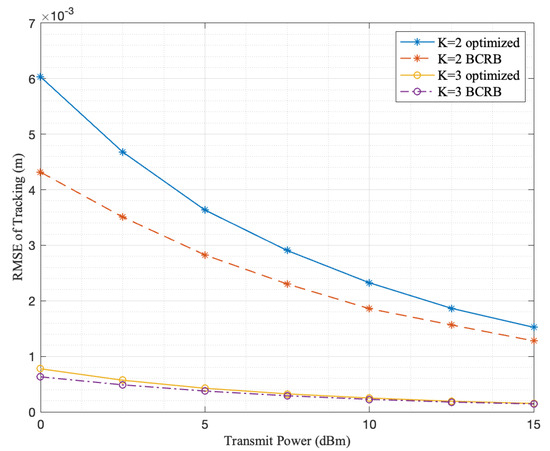
Figure 8.
Performance illustration with different numbers of RISs K set by 2 and 3 and transmit power P varying from to . Other variable parameters are fixed at , , , , .
To exploit the effect of the number of RIS elements, we consider other variable parameters fixed at , , , , , the transmit power P varying from to , and the numbers of RISs’ elements varying in , , and . As illustrated in Figure 9, with the increment in the number of RIS elements, the performance of our tracking algorithm improves. Further, we can find that with the increment in the number of elements, the tracking accuracy of the proposed scheme is closer to the BCRB. Moreover, as indicated by the gaps between three groups of lines with different , the improvement of accuracy with the increment of becomes less significant when the same number of elements is added.
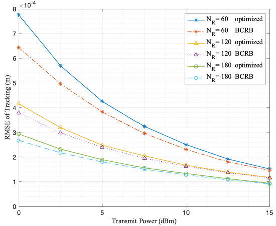
Figure 9.
Performance illustration with different numbers of RIS elements set by , and and transmit power P varying from to . Other variable parameters are fixed at , , , , .
From the above two sets of experiments, it can be concluded that with abundant RISs deployed and optimization of their phase shift, high accuracy can be achieved in harsh localization environments. In all cases, the performance of our tracking scheme improves and approximates BCRB more closely with the increment of transmit power.
6. Conclusions
In summary, concerning the mobility of users and the potential obstruction of LoS paths, a multi-user tracking system based on EKF is designed by directly utilizing the non-linear relationship between the signals received at the BS antennas and the coordinates of the moving targets, where the temporal correlations between each user’s coordinate changes are fully exploited. An optimization scheme of passive phase shift design at the RISs is devised by minimizing the derived BCRB and solving the problem by leveraging the GD method.
Numerical results indicate that the accuracy of our tracking scheme is affected by a series of factors. With the increment of transmit power, the number of BS antennas, users’ mobility, and the number of RISs or RIS elements, the proposed method attains higher tracking accuracy and approaches closer to the BCRB in the conducted simulations. High-precision multi-user tracking via a single BS can be realized by abundant RISs deployed and optimized, even in harsh localization environments. Future works will entail the tracking of multiple users under more variable scenarios, i.e., monitoring the existence of the LoS path between the RISs and the users and switching the adopted tracking model under varied circumstances.
Author Contributions
Conceptualization, Y.M. and R.W.; methodology, Y.M. and R.W.; software, Y.M. and R.W.; validation, Y.M. and R.W.; formal analysis, Y.M. and R.W.; investigation, Y.M.; resources, Y.M. and R.W.; data curation, Y.M. and R.W.; writing—original draft preparation, Y.M.; writing—review and editing, Y.M., R.W., E.L. and I.S.; visualization, Y.M.; supervision, R.W., E.L. and I.S.; project administration, R.W., E.L. and I.S.; funding acquisition, R.W., E.L. and I.S. All authors have read and agreed to the published version of the manuscript.
Funding
This research was funded by the National Natural Science Foundation of China under Grant 62271352, the Shanghai Science and Technology Innovation Action Plan Project No. 21220713100 and the Natural Science Foundation of Shanghai under Grant 22ZR1465100.
Institutional Review Board Statement
Not applicable.
Informed Consent Statement
Not applicable.
Data Availability Statement
The data presented in this study are available in this article.
Conflicts of Interest
The authors declare no conflicts of interest.
Appendix A
Corresponding to the above processing of received signals, we expand the Jacobian matrix into , and . Denote , and , and can be calculated by
For each item in and , we can denote
where
where and . It is assumed that the vertical displacements of the users are almost negligible, i.e., in changes slowly with respect to and , where and .
Appendix B
References
- Wymeersch, H.; Shrestha, D.; De Lima, C.M.; Yajnanarayana, V.; Richerzhagen, B.; Keskin, M.F.; Schindhelm, K.; Ramirez, A.; Wolfgang, A.; De Guzman, M.F.; et al. Integration of communication and sensing in 6G: A joint industrial and academic perspective. In Proceedings of the 2021 IEEE 32nd Annual International Symposium on Personal, Indoor and Mobile Radio Communications (PIMRC), Helsinki, Finland, 13–16 September 2021; pp. 1–7. [Google Scholar]
- Zhang, J.A.; Liu, F.; Masouros, C.; Heath, R.W.; Feng, Z.; Zheng, L.; Petropulu, A. An overview of signal processing techniques for joint communication and radar sensing. IEEE J. Sel. Top. Signal Process. 2021, 15, 1295–1315. [Google Scholar] [CrossRef]
- Liu, F.; Cui, Y.; Masouros, C.; Xu, J.; Han, T.X.; Eldar, Y.C.; Buzzi, S. Integrated sensing and communications: Toward dual-functional wireless networks for 6G and beyond. IEEE J. Sel. Areas Commun. 2022, 40, 1728–1767. [Google Scholar] [CrossRef]
- Bourdoux, A.; Barreto, A.N.; van Liempd, B.; de Lima, C.; Dardari, D.; Belot, D.; Lohan, E.S.; Seco-Granados, G.; Sarieddeen, H.; Wymeersch, H.; et al. 6G white paper on localization and sensing. arXiv 2020, arXiv:2006.01779. [Google Scholar]
- Jeong, S.; Simeone, O.; Haimovich, A.; Kang, J. Beamforming design for joint localization and data transmission in distributed antenna system. IEEE Trans. Veh. Technol. 2014, 64, 62–76. [Google Scholar] [CrossRef]
- Zheng, Y.; Sheng, M.; Liu, J.; Li, J. Exploiting AoA estimation accuracy for indoor localization: A weighted AoA-based approach. IEEE Wirel. Commun. Lett. 2018, 8, 65–68. [Google Scholar] [CrossRef]
- Zhang, W.; Yin, Q.; Chen, H.; Gao, F.; Ansari, N. Distributed angle estimation for localization in wireless sensor networks. IEEE Trans. Wirel. Commun. 2012, 12, 527–537. [Google Scholar] [CrossRef]
- Zou, Y.; Liu, H. TDOA localization with unknown signal propagation speed and sensor position errors. IEEE Commun. Lett. 2020, 24, 1024–1027. [Google Scholar] [CrossRef]
- Lohrasbipeydeh, H.; Gulliver, T.A. Unknown RSSD-based localization CRLB analysis with semidefinite programming. IEEE Trans. Commun. 2019, 67, 3791–3805. [Google Scholar] [CrossRef]
- Wang, Z.; Liu, Z.; Shen, Y.; Conti, A.; Win, M.Z. Location awareness in beyond 5G networks via reconfigurable intelligent surfaces. IEEE J. Sel. Areas Commun. 2022, 40, 2011–2025. [Google Scholar] [CrossRef]
- Wu, Q.; Zhang, S.; Zheng, B.; You, C.; Zhang, R. Intelligent reflecting surface-aided wireless communications: A tutorial. IEEE Trans. Commun. 2021, 69, 3313–3351. [Google Scholar] [CrossRef]
- Di Renzo, M.; Zappone, A.; Debbah, M.; Alouini, M.S.; Yuen, C.; De Rosny, J.; Tretyakov, S. Smart radio environments empowered by reconfigurable intelligent surfaces: How it works, state of research, and the road ahead. IEEE J. Sel. Areas Commun. 2020, 38, 2450–2525. [Google Scholar] [CrossRef]
- Yuan, X.; Zhang, Y.J.A.; Shi, Y.; Yan, W.; Liu, H. Reconfigurable-intelligent-surface empowered wireless communications: Challenges and opportunities. IEEE Wirel. Commun. 2021, 28, 136–143. [Google Scholar] [CrossRef]
- Huang, C.; Hu, S.; Alexandropoulos, G.C.; Zappone, A.; Yuen, C.; Zhang, R.; Di Renzo, M.; Debbah, M. Holographic MIMO surfaces for 6G wireless networks: Opportunities, challenges, and trends. IEEE Wirel. Commun. 2020, 27, 118–125. [Google Scholar] [CrossRef]
- Xing, Z.; Wang, R.; Yuan, X. Passive beamforming design for reconfigurable intelligent surface enabled integrated sensing and communication. arXiv 2022, arXiv:2206.00525. [Google Scholar] [CrossRef]
- Cai, C.; Yuan, X.; Yan, W.; Huang, Z.; Liang, Y.C.; Zhang, W. Hierarchical passive beamforming for reconfigurable intelligent surface aided communications. IEEE Wirel. Commun. Lett. 2021, 10, 1909–1913. [Google Scholar] [CrossRef]
- Wymeersch, H.; He, J.; Denis, B.; Clemente, A.; Juntti, M. Radio localization and mapping with reconfigurable intelligent surfaces. arXiv 2019, arXiv:1912.09401. [Google Scholar]
- Björnson, E.; Wymeersch, H.; Matthiesen, B.; Popovski, P.; Sanguinetti, L.; de Carvalho, E. Reconfigurable intelligent surfaces: A signal processing perspective with wireless applications. IEEE Signal Process. Mag. 2022, 39, 135–158. [Google Scholar] [CrossRef]
- Wymeersch, H.; He, J.; Denis, B.; Clemente, A.; Juntti, M. Radio localization and mapping with reconfigurable intelligent surfaces: Challenges, opportunities, and research directions. IEEE Veh. Technol. Mag. 2020, 15, 52–61. [Google Scholar] [CrossRef]
- Elzanaty, A.; Guerra, A.; Guidi, F.; Alouini, M.S. Reconfigurable intelligent surfaces for localization: Position and orientation error bounds. IEEE Trans. Signal Process. 2021, 69, 5386–5402. [Google Scholar] [CrossRef]
- Zhang, H.; Zhang, H.; Di, B.; Bian, K.; Han, Z.; Song, L. Metalocalization: Reconfigurable intelligent surface aided multi-user wireless indoor localization. IEEE Trans. Wirel. Commun. 2021, 20, 7743–7757. [Google Scholar] [CrossRef]
- Lin, Y.; Jin, S.; Matthaiou, M.; You, X. Channel estimation and user localization for IRS-assisted MIMO-OFDM systems. IEEE Trans. Wirel. Commun. 2021, 21, 2320–2335. [Google Scholar] [CrossRef]
- Wang, W.; Zhang, W. Joint beam training and positioning for intelligent reflecting surfaces assisted millimeter wave communications. IEEE Trans. Wirel. Commun. 2021, 20, 6282–6297. [Google Scholar] [CrossRef]
- He, J.; Wymeersch, H.; Sanguanpuak, T.; Silvén, O.; Juntti, M. Adaptive beamforming design for mmWave RIS-aided joint localization and communication. In Proceedings of the 2020 IEEE Wireless Communications and Networking Conference Workshops (WCNCW), Seoul, Republic of Korea, 25–28 May 2020; pp. 1–6. [Google Scholar]
- Dardari, D.; Decarli, N.; Guerra, A.; Guidi, F. LOS/NLOS near-field localization with a large reconfigurable intelligent surface. IEEE Trans. Wirel. Commun. 2021, 21, 4282–4294. [Google Scholar] [CrossRef]
- Zhang, H.; Zhang, H.; Di, B.; Bian, K.; Han, Z.; Song, L. Towards ubiquitous positioning by leveraging reconfigurable intelligent surface. IEEE Commun. Lett. 2020, 25, 284–288. [Google Scholar] [CrossRef]
- Nguyen, C.L.; Georgiou, O.; Gradoni, G.; Di Renzo, M. Wireless fingerprinting localization in smart environments using reconfigurable intelligent surfaces. IEEE Access 2021, 9, 135526–135541. [Google Scholar] [CrossRef]
- Abrardo, A.; Dardari, D.; Di Renzo, M. Intelligent reflecting surfaces: Sum-rate optimization based on statistical position information. IEEE Trans. Commun. 2021, 69, 7121–7136. [Google Scholar] [CrossRef]
- Zhou, W.; Xia, J.; Li, C.; Fan, L.; Nallanathan, A. Joint precoder, reflection coefficients, and equalizer design for IRS-assisted MIMO systems. IEEE Trans. Commun. 2022, 70, 4146–4161. [Google Scholar] [CrossRef]
- Dai, J.; Zhu, F.; Pan, C.; Ren, H.; Wang, K. Statistical CSI-based transmission design for reconfigurable intelligent surface-aided massive MIMO systems with hardware impairments. IEEE Wirel. Commun. Lett. 2021, 11, 38–42. [Google Scholar] [CrossRef]
- Lin, Y.; Jin, S.; Matthaiou, M.; You, X. Conformal IRS-Empowered MIMO-OFDM: Channel Estimation and Environment Mapping. IEEE Trans. Commun. 2022, 70, 4884–4899. [Google Scholar] [CrossRef]
- Fascista, A.; Keskin, M.F.; Coluccia, A.; Wymeersch, H.; Seco-Granados, G. RIS-aided joint localization and synchronization with a single-antenna receiver: Beamforming design and low-complexity estimation. IEEE J. Sel. Top. Signal Process. 2022, 16, 1141–1156. [Google Scholar] [CrossRef]
- Rahal, M.; Denis, B.; Keykhosravi, K.; Keskin, M.F.; Uguen, B.; Wymeersch, H. Constrained RIS phase profile optimization and time sharing for near-field localization. In Proceedings of the 2022 IEEE 95th Vehicular Technology Conference: (VTC2022-Spring), Helsinki, Finland, 19–22 June 2022; pp. 1–6. [Google Scholar]
- Gao, P.; Lian, L.; Yu, J. Wireless area positioning in RIS-assisted mmWave systems: Joint passive and active beamforming design. IEEE Signal Process. Lett. 2022, 29, 1372–1376. [Google Scholar] [CrossRef]
- Feng, Z.; Wang, B.; Zhao, Y.; Luan, M.; Hu, F. Power optimization for target localization with reconfigurable intelligent surfaces. Signal Process. 2021, 189, 108252. [Google Scholar] [CrossRef]
- Teng, B.; Yuan, X.; Wang, R.; Jin, S. Bayesian user localization and tracking for reconfigurable intelligent surface aided MIMO systems. IEEE J. Sel. Top. Signal Process. 2022, 16, 1040–1054. [Google Scholar] [CrossRef]
- Palmucci, S.; Guerra, A.; Abrardo, A.; Dardari, D. Two-Timescale Joint Precoding Design and RIS Optimization for User Tracking in Near-Field MIMO Systems. IEEE Trans. Signal Process. 2023, 71, 3067–3082. [Google Scholar] [CrossRef]
- Han, Y.; Tang, W.; Jin, S.; Wen, C.K.; Ma, X. Large intelligent surface-assisted wireless communication exploiting statistical CSI. IEEE Trans. Veh. Technol. 2019, 68, 8238–8242. [Google Scholar] [CrossRef]
- Hu, C.; Dai, L.; Han, S.; Wang, X. Two-timescale channel estimation for reconfigurable intelligent surface aided wireless communications. IEEE Trans. Commun. 2021, 69, 7736–7747. [Google Scholar] [CrossRef]
- Zhi, K.; Pan, C.; Ren, H.; Wang, K.; Elkashlan, M.; Di Renzo, M.; Schober, R.; Poor, H.V.; Wang, J.; Hanzo, L. Two-timescale design for reconfigurable intelligent surface-aided massive MIMO systems with imperfect CSI. IEEE Trans. Inf. Theory 2022, 69, 3001–3033. [Google Scholar] [CrossRef]
- Yu, Z.; Hu, X.; Liu, C.; Peng, M.; Zhong, C. Location sensing and beamforming design for IRS-enabled multi-user ISAC systems. IEEE Trans. Signal Process. 2022, 70, 5178–5193. [Google Scholar] [CrossRef]
- Teng, B.; Yuan, X.; Wang, R. Variational Bayesian Multiuser Tracking for Reconfigurable Intelligent Surface Aided MIMO-OFDM Systems. arXiv 2023, arXiv:2304.11884. [Google Scholar]
- Tichavsky, P.; Muravchik, C.; Nehorai, A. Posterior Cramer-Rao bounds for discrete-time nonlinear filtering. IEEE Trans. Signal Process. 1998, 46, 1386–1396. [Google Scholar] [CrossRef]
- Yan, J.; Liu, H.; Jiu, B.; Bao, Z. Power allocation algorithm for target tracking in unmodulated continuous wave radar network. IEEE Sens. J. 2014, 15, 1098–1108. [Google Scholar]
- Xie, M.; Yi, W.; Kirubarajan, T.; Kong, L. Joint node selection and power allocation strategy for multitarget tracking in decentralized radar networks. IEEE Trans. Signal Process. 2017, 66, 729–743. [Google Scholar] [CrossRef]
- Razaviyayn, M.; Hong, M.; Luo, Z.Q. A unified convergence analysis of block successive minimization methods for nonsmooth optimization. SIAM J. Optim. 2013, 23, 1126–1153. [Google Scholar] [CrossRef]
- Bertsekas, D.P. Nonlinear programming. J. Oper. Res. Soc. 1997, 48, 334. [Google Scholar] [CrossRef]
- Song, J.; Babu, P.; Palomar, D.P. Sequence design to minimize the weighted integrated and peak sidelobe levels. IEEE Trans. Signal Process. 2015, 64, 2051–2064. [Google Scholar] [CrossRef]
- Sun, Y.; Babu, P.; Palomar, D.P. Majorization-minimization algorithms in signal processing, communications, and machine learning. IEEE Trans. Signal Process. 2016, 65, 794–816. [Google Scholar] [CrossRef]
- Hjorungnes, A.; Gesbert, D. Complex-valued matrix differentiation: Techniques and key results. IEEE Trans. Signal Process. 2007, 55, 2740–2746. [Google Scholar] [CrossRef]
- Akdeniz, M.R.; Liu, Y.; Samimi, M.K.; Sun, S.; Rangan, S.; Rappaport, T.S.; Erkip, E. Millimeter wave channel modeling and cellular capacity evaluation. IEEE J. Sel. Areas Commun. 2014, 32, 1164–1179. [Google Scholar] [CrossRef]
Disclaimer/Publisher’s Note: The statements, opinions and data contained in all publications are solely those of the individual author(s) and contributor(s) and not of MDPI and/or the editor(s). MDPI and/or the editor(s) disclaim responsibility for any injury to people or property resulting from any ideas, methods, instructions or products referred to in the content. |
© 2023 by the authors. Licensee MDPI, Basel, Switzerland. This article is an open access article distributed under the terms and conditions of the Creative Commons Attribution (CC BY) license (https://creativecommons.org/licenses/by/4.0/).