Abstract
Urban railway tracks are the primary modes of transportation in many cities worldwide. Track vehicles mostly use DC from overhead lines, and rails are used as return conductors. Because it is challenging to fully insulate the rail and ensure high rail-to-ground resistance, current leaks from the rail to the lower part of the track. This current is referred to as stray current. To determine the detrimental effects of stray current on the rail and fastening system components, we performed a laboratory simulation of the stray current on four real-scale samples of the entire rail with all fastening components. The difference among these four samples was the type of fastening system used. Tests were performed under dry condition and at different water levels. After testing, the samples were visually inspected. Under dry conditions, corrosion occurred on the elements in contact with the concrete, and under immersed conditions, the current leaked from all components of the fastening system directly into the water, causing harmful local deterioration. The characteristics of the fastening systems are defined to satisfy other parameters, but not to prevent stray currents and ensure high rail-to-ground resistance. The aim of this study was to demonstrate the effects of stray current on the rail and fastening system and to prove the importance of providing adequate drainage of the track and using a fastening system that is insulated and does not allow the current to leak from the rail.
1. Introduction
Owing to their high capacity and velocity, urban railway tracks are the main type of transportation in many cities worldwide. Currently, urban track systems mostly use the DC traction power supply mode, and rails are normally used as return conductors from vehicles to substation [1,2,3,4]. The electrical resistance of the rail results from creating a potential drop in the rail, and because it is impossible to completely insulate the rail from its surroundings, part of the current leaks into the track bed and soil [1,5,6,7]. This current is called stray current. Stray current enters nearby metal objects that have a lower resistance than soil, such as buried metal pipelines or steel in reinforced concrete, and flows back to the source [8,9,10].
The current path through a rail or other metal object can be very long and not harmful; however, stray current corrosion starts at the point where the current leaves the metal and enters the electrolyte [11,12]. Stray current corrosion became a source of concern for transit authorities and utility companies immediately after the first electrified tracks began to operate. Initially, it was thought that the corrosion problem was caused by a chemical mixture of the soil; however, after some research, it became clear that soil alone could not cause the severe corrosion found in rail bases and nearby utilities. It was concluded that the cause of this corrosion was a stray current [13,14]. Stray current corrosion is an electrochemical process that involves two simultaneous reactions. A cathodic reaction occurs in the cathodic zone, where the current enters the metal structure or rail, whereas an anodic reaction occurs where the current leaves the rail or metal structure and enters the soil or other electrolyte, called the anodic zone [15,16,17,18,19]. Corrosion and metal loss occur in the anodic zone.
Currently, most studies [20,21,22,23,24,25] focus on stray current corrosion in pipelines or on stray current simulations and modeling [7,16,26,27]. The main objectives of some conducted studies are listed in Table 1. Even though minor corrosion damage is sufficient to compromise the integrity of pipelines, it is not surprising that many researchers have focused on analyzing the detrimental impact of stray current corrosion on pipelines; however, stray current can also have detrimental effects on urban tracks and lead to the degradation of rails and rail fastening systems. Corrosion itself does not cause a significant mass loss in the track and is generally hidden and difficult to detect by visual inspection [28]. This could be one of the main reasons why rail corrosion has not yet attracted sufficient attention and has become a major concern for operators. However, a small loss of rail material can lead to a significant change in the material properties or even act as a “stress concentrator” for the development of cracks [28,29,30,31,32]. Conditions such as sunlight, relative humidity, temperature, and atmosphere have major impacts on corrosion. In addition, salt deposition is an important factor that increases the corrosion rate [33].

Table 1.
Review of studies focusing on stray current.
According to Faraday’s law of electrolysis, a current of 1 A results in a loss of 9.1 kg of steel per year [26]. The EN 50122-2:2022 standard [41] states that experience indicates that no damage occurs in tracks if the average stray current per length does not exceed 2.5 mA/m. The methods used to reduce the stray current at the source can be divided into two groups [19,20,42,43].
- -
- Decreasing the longitudinal electrical resistance of the rails, and
- -
- Increasing the rail-to-ground resistance.
The shape and material properties of rails are mainly selected according to mechanical requirements, whereas the electrical properties are related to the background [44,45,46]. However, the longitudinal electrical resistance of the rail can be reduced by methods such as using rails with a larger cross section and reducing the distance between substations [47]. Because the electrical resistance of the rail depends on the rail cross section, the resistance increases during exploitation owing to rail head wear and cross-sectional thinning due to the corrosion process. According to [34], rail wear can be caused by increasing the rail electrical resistance by 19%.
According to [35], the rail-to-ground resistance is required to control the stray current. The resistance depends on the type of track and rail insulation [17]. For tracks with continuously supported and fastened rails, where the rails are fully insulated with an elastic material, a high rail-to-ground resistance is achieved and stray current is prevented. For tracks with discretely supported and fastened rails, it is very difficult to ensure sufficient resistance between the rail and ground; therefore, stray currents can greatly affect the track and metal objects near the track. Because the type and properties of fastening systems are selected depending on the required elasticity of the track, planned traffic load, and type of rail [48], the electrical resistance of the fastening system is not defined in the specifications. According to [36,42], even perfect rail insulation lasts only a few years if the tracks are not properly maintained; therefore, rail-to-ground resistance depends on the electrical resistance of the concrete base layer and the soil, which can vary greatly depending on the location of the tracks. Consequently, the rail-to-ground resistance values provided in the guidelines vary across countries for the same type of track construction, as shown in [49,50]. The corrosion rate and stray current are higher in closed urban tracks because it is very difficult to provide adequate drainage, and the tracks dry very slowly. Thus, the remaining water accelerates the corrosion and stray current. Urban tracks embedded in lanes shared by road vehicles (Figure 1a,b) are also exposed to chlorides that are used in winter to prevent icing of the pavement [29]. These chlorides dissolve in water and enter the tracks [30], which results in a decrease in the electrical resistance between the rail and ground.
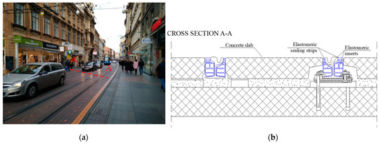
Figure 1.
(a) Paved tram track structure in Zagreb, Croatia, built as part of the road surface, as a discretely fastened track and its (b) cross section.
Compared to the mass of the rail and the metal parts of the fastening system, stray current corrosion does not cause a significant loss of material on the track, but the deterioration caused by stray current is localized. If it occurs in the places where the rail is fastened to the concrete base using a discrete fastening system, the corrosion combined with the traffic load may lead to breakage of the rail foot and the elements of the fastening system [51]. In this case, the rail is no longer fastened to the base, and traffic safety may be compromised. According to [48], in most urban track systems the main task of the rail fastening system is to position and fasten the rails and transfer the vehicle load from the rails to the track substructure. The type and characteristics of the fastening system are selected depending on the required elasticity of the track, planned load, and rail type. The research carried out in this study shows that the type of fastening system also has an influence on the stray current and that the prevention of stray current must be one of the tasks that the fastening system must fulfill.
This paper is divided into five sections. State-of-the-art methods are presented in the introduction (Section 1). Section 2 explains the motivation for conducting this study and research objectives. The materials and methods are described in Section 3. Section 3 also describes the test samples and the differences between them. The results are presented in Section 4. In Section 5, a tabular overview of the influence of stray currents on the observed test samples is provided, and the results of the research are summarized. Finally, Section 6 presents the main conclusions.
2. Research Objectives
Based on the state of the art, it can be concluded that previous studies are mostly focused on the following:
- -
- modeling of stray currents in track construction, especially in metro systems
- -
- analysis of rail potential
- -
- the effects of stray currents on endangered structures near the tracks, particularly pipelines
- -
- analysis of methods for protecting buried pipelines from the effects of stray currents.
However, previous research has not analyzed the effects of stray currents on rails and fastening systems in urban railway tracks, which are the main sources of stray currents. After identifying the damage caused by the stray currents in the track, effective measures to protect the track can be determined. This reduces the stray current and prevents damage to structures near the track.
To define the negative effects of stray currents on urban railway tracks, the authors performed a laboratory simulation of stray currents on four real-scale samples of the entire rail with all the fastening components. The difference among these four samples was the type of fastening system used. The fastening systems used for this test are characteristic of the tramway infrastructure in the city of Zagreb, Croatia, which has one of the highest traffic loads in Europe and where the problem of stray currents has been recognized. The samples prepared for testing were placed in plastic tubs to allow the tests to be performed under dry conditions and at different water levels. Different water levels simulate different conditions that can occur in tracks when drainage is inadequate and water is retained in the track.
3. Materials and Methods
3.1. Sample Description and Preparation
Laboratory tests were performed on four different types of fastening systems that are characteristic of the tram track infrastructure in Zagreb: ZG 3/2, PPE, DEPP, and ZG 21-CTT. ZG 3/2 and PPE are direct fastening systems, where the rails are laid on elastic rail pads and steel plates and fastened using clips and anchor bolts (Figure 2 and Figure 3). Anchor bolts were used to anchor the fastening system to a concrete base. In the PPE fastening system, an elastomer pad was placed between the steel plate and the leveling layer, whereas in the ZG 3/2 fastening system, the steel plate was in direct contact with the leveling layer. In the ZG 3/2 fastening system, the SKL-2 clip was placed on a steel rib, whereas in the PPE fastening system, the SKL-1 clip was placed on a plastic rib.
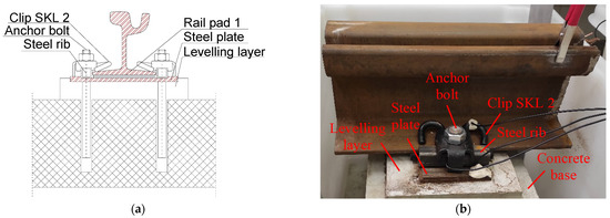
Figure 2.
Fastening system ZG 3/2: (a) cross section and (b) sample for testing.
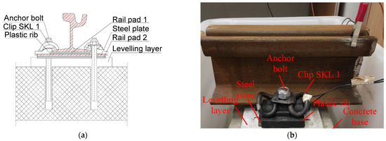
Figure 3.
Fastening system PPE: (a) cross section and (b) sample for testing.
In the DEPP and Zagreb 21-CTT fastening systems, the rails are laid on the rail pad and steel plate but are fastened to the steel plate using clips and T-bolts (Figure 4 and Figure 5). The anchor bolts are dislocated and used only to anchor the fastening system to the concrete base. In the Zagreb 21-CTT fastener, the underside of the steel plate is vulcanized. The bores for the anchor bolts on the steel plate are also vulcanized such that the anchor bolts do not directly contact the steel plate (Figure 5a).
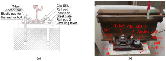
Figure 4.
Fastening system DEPP: (a) cross section and (b) sample for testing.
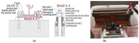
Figure 5.
Fastening system Zagreb 21-CTT: (a) cross section and (b) sample for testing.
First, concrete bases with dimensions of 60 × 30 × 25 cm were fabricated for the samples. The leveling layers were created as in situ, with the rails adjusted primarily by direction and height. For the test samples, the steel base plates were raised approximately 5 cm above the concrete block, corresponding to the height of the leveling layer on the tracks. For the PPE, DEPP, and Zagreb 21-CTT fastening systems, the leveling layers of the concrete reinforced with synthetic microfibers were cast at the middle of the height of the elastomeric pads, whereas for the ZG 3/2 fastening system, the leveling layer was cast at half the height of the steel plate because there was no elastomer pad under the steel plate.
3.2. Methodology
The samples were placed in plastic tubes and treated with a DC current from a laboratory power supply. Each sample was connected to a separate DC source. A voltage of 26 V was applied to the samples, and the current value depended on their electrical resistance. The rail was connected to the positive terminal of the power supply, and the circuit was closed using a steel rib built into the concrete (Figure 6a). In this circuit, current flows into the rail and fastening system and through the electrolyte (in these cases, concrete or water) back to the negative terminal of the power supply.
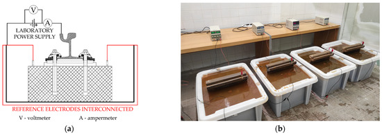
Figure 6.
(a) Current circuit during testing and (b) samples during testing.
The experiment was performed in three different states of the samples:
- -
- The samples are dry (Figure 7a),
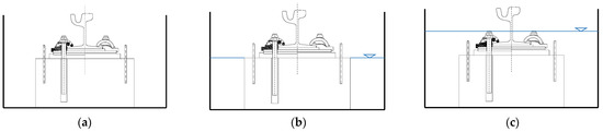 Figure 7. Different water levels in which the samples were immersed: (a) dry condition, (b) water level to the top of the concrete block, and (c) immersed condition.
 - -
- Water on the top of the concrete base (Figure 7b)
- -
- In the immersed condition: the water level was half the height of the neck of the rail (Figure 7c).
Different water levels simulate different conditions that can occur on tram tracks. In tracks embedded in lanes shared by road vehicles, the drying process is very slow; therefore, the concrete base is wet for most of the year. These conditions were simulated using the water level at the top of the concrete base. If track drainage is inadequate, water will remain in the track, resulting in direct contact between the rail and the fastening system with the electrolyte. These conditions were simulated by immersing the samples in water to half the height of the neck of the rail. Before immersing the samples in water, the electrical conductivity of water was measured using an SI Analytics Lab 945 conductometer. The electrical conductivity of water was 0.0775 S/m. The electrical conductivity of water affects the electrical resistance of the entire sample. Therefore, it is important that the conductivity of water be the same in all samples. Notably, the electrical resistance of the water retained in the track structure depends on the substances dissolved in the water, mainly salt. This experiment can also be performed using water containing dissolved salts to accelerate the corrosion process. However, because the aim of this study was to determine the influence of stray currents on rails and fasteners, the experiment was carried out with tap water with a defined electrical conductivity.
The experiment lasted 191 days, during which, for 92 days, the water level was at half the height of the rail neck, and for 74 days, the water level was on the concrete base.
During testing, the current and voltage were measured, and the samples were periodically visually inspected. The current was recorded using a multimeter GWInstek GDM9061, and the voltage was measured for all the components of the fastening systems. Measurements were taken at the beginning of the test, when the samples were dry, when the water level was at the top of the concrete base (case I), in the immersed condition (case II), and after the test was finished and the water level was lowered by the top of the concrete base (case III). The voltage was measured between the analyzed elements (rail, clip, anchor bolt, steel plate, T-bolt, and steel rib) and the negative terminal of the current source. Before starting the measurements, the resistance of the testing equipment was measured to exclude its influence on the measurement results.
Because the accumulation of corrosion products under immersion conditions increased the electrical resistance, the water in the tubs was changed every week to maintain a constant current.
4. Results
4.1. Analysis of the Voltage in Fastening System Components
The average currents detected in each sample in all three test cases are listed in Table 2.
Table 2.
Measured current value for each testing case.
In the PPE and ZG 3/2 fastening systems, the same voltage was observed for all components (Table 3), which indicates that all components of the fastening systems were in direct contact; no insulating material was present that could stop the flow of current from the rail to the clip and from the clip to other elements of the fastening system. Owing to this direct contact, when dry, the current leaks from the rail through the fastening system to the concrete base and track substructure. The only factor affecting the resistance between the rail and ground in this case is the electrical resistance of the concrete base. Thus, it can be concluded that the direct fastening system does not exhibit good properties for preventing stray currents.
Table 3.
Measured voltage in fastening system components before, during, and after testing.
For the DEPP and Zagreb 21-CTT indirect fastening systems, a voltage drop between the anchor bolts and the steel plate was observed at the beginning of the test (Table 3). This voltage drop indicates that the bolts are not in direct contact with the steel plate, which will be analyzed in more detail in the following subsection.
4.1.1. Analysis of the Voltage in Anchor Bolts in the DEPP Fastening System
In the DEPP fastening system, the diameters of the bores for the anchor bolts on the steel plate were larger than those for the bolts (Figure 8a). The contact between the steel plate and anchor bolt was made by the elastomer pad for the anchor bolts, which was proven by measuring the voltage in the anchor bolts in two cases:
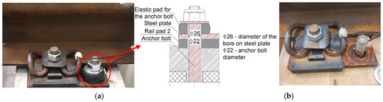
Figure 8.
DEPP fastening system: (a) Case 1: elastic pad and nut at the anchor bolt. (b) Case 2: elastic pad and nut removed from the anchor bolts.
The measured voltages are shown in Figure 9. After removing the elastic pads from the anchor bolts (case 2), the voltage in the anchor bolts was 1.7 V on bolt 1 and 1.4 V on bolt 2, indicating that the electrical connection between the anchor bolt and steel plate was established through the elastomer pad.
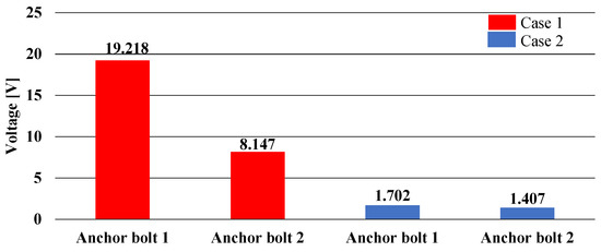
Figure 9.
Measured voltages in anchor bolts for cases 1 and 2 for the DEPP fastening system.
In addition, notably, a large difference was observed between the voltages measured in Case 1 for anchor bolts 1 and 2 (Figure 9), even though the anchor bolts were connected to the steel plates with the same type of nuts and elastic pads. The electrical resistance of the elastic pads was measured to determine whether the different resistance values were responsible for the different voltages in the anchor bolts. The resistance of the elastic pad for anchor bolt 1 was 2.29 kΩ, and the resistance of the pad for anchor bolt 2 was 1980.28 kΩ, which confirmed the original assumption that the differing values of the electrical resistance of the elastic pads caused the difference in the measured voltages in the anchor bolts.
4.1.2. Voltage in Anchor Bolts in Zagreb 21-CTT Fastening System
In the Zagreb 21-CTT fastening system, the underside of the steel plate and bores for the anchor bolts at the plate were vulcanized (Figure 10a) to prevent current from leaking from the steel plate to the anchor bolts and lower parts of the track. Because the steel plate of the Zagreb 21-CTT fastening system is vulcanized, the anchor bolts should be isolated from the plate. However, a high voltage was detected in anchor bolt 2. All elastomer elements of the Zagreb 21-CTT fastening system were made of the same material during vulcanization. To determine the electrical resistivity of the material, measurements were performed using a GWInstek GDM9061 multimeter and a direct-current source on the rail pad. The rail pad was placed between the steel plate and rail. The rail was connected to the positive terminal of the current source, and the steel plate was connected to the negative terminal (Figure 10b). The current and voltage were measured using a multimeter, and the calculated electrical resistivity of the rail pad was 1.14 kΩm. The low electrical resistivity of the elastomer elements in the Zagreb 21-CTT fastening system resulted in a current flow from the steel plate to the anchor bolts, which led to a high voltage detected in the anchor bolts.
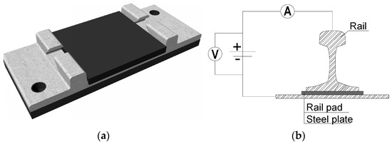
Figure 10.
(a) Vulcanized steel plate for the Zagreb 21-CTT fastening system with the rail pad. (a) Cross section of the Zagreb 21-CTT fastening system in contact with the steel plate and anchor bolt CTT. (b) Current circuit during the measurement of the electrical resistance of the rail pad.
Because electrical resistance is not one of the defined properties that elastomer elements used in these fastening systems must satisfy, the electrical resistance between the steel plate and anchor bolt depends on the materials and fillers used to vulcanize the steel plate and produce an elastic pad for the anchor bolt. Currently, the most used filler is soot, whose electrical resistivity varies from 0.0044 to 1.50 Ωm. To prevent current from flowing from the steel plate to the anchor bolts, the electrical resistance of the elastomer elements used should be high.
4.2. Visual Inspection and Corrosion Classification on Fastening System Components
During and after the experiment, the samples were visually inspected and the detrimental effects of stray currents on the rail and fastening system were determined. Before the samples were immersed in water, only surface corrosion was observed; however, after the testing was completed, severe localized damage to the rail foot and fastening system components was observed in all samples. Furthermore, because the corrosion products have a significantly larger volume, their deposits at the contact of the anchor bolts with the concrete cause cracks in the concrete base and leveling layer. The conditions of all the samples after testing are shown in Figure 11.
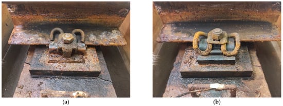
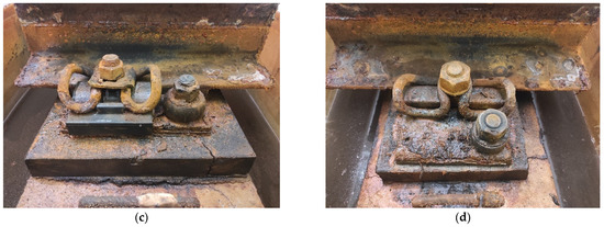
Figure 11.
Conditions of all samples after testing was completed: (a) ZG 3/2, (b) PPE, (c) DEPP, (d) Zagreb 21-CTT.
When the ZG 3/2 fastening system was dry, and the water level was at the top of the concrete base, no local corrosion was observed in the elements of the rail or fastening system. Under these conditions, current flows from the rail through the rail clip and steel rib to the steel plate and anchor bolts. From the bolts and plate, the current flowed into the concrete base and leveling layer, such that corrosion occurred only at the point of contact of the steel plate with the leveling layer and at the point of contact of the anchor bolts with the concrete base. Under immersed conditions, current flows from the rail, steel rib, and steel plate directly into the water, causing corrosion and deterioration of the components of the fastening system. In the PPE fastening system, under dry conditions, despite the insulation pads used under the rail, clip, and steel plate, current can leak directly into the concrete and return to the negative terminal at the laboratory power supply because of the direct contact between the rail, clip, and anchor bolt. When dry, only the anchor bolts are in contact with the concrete; therefore, they corrode. When the water level reaches half the height of the rail neck, the current from all the elements flows into the water and causes corrosion. Under dry conditions, in the DEPP and Zagreb 21-CTT fastening systems, corrosion can also occur only at the anchor bolt, i.e., at the part of the bolt that is in contact with the electrolyte; however, because the anchor bolts in these fastening systems are partly insulated, the corrosion rate will be lower than that on the ZG 3/2 and PPE fastening systems. Visual inspection revealed that the current did not flow uniformly from the metal elements into the water when the samples were immersed. Discharge points occurred on the metal surface where localized material loss was observed. In addition to the corrosion of rails and fastening systems, cracks were observed in the leveling layers and concrete bases. These cracks resulted from the deposition of corrosion products at the contact between the bolt and the concrete. The cracks were classified based on a visual inspection (Figure 11) and were divided into three groups: large, medium, and small.
The ZG 3/2 fastening system exhibits cracks across the entire width of the concrete base (Figure 11a). The maximum measured width of the crack was 4.5 mm, which is considered large. In the PPE and DEPP fastening systems (Figure 11b,c), cracks were observed in the leveling layer and in the concrete base near the anchor bolts, which are referred to as medium cracks. The maximum crack widths for the DEPP- and PPE-fastening systems were 2 mm, and the maximum crack width for the PPE fastening system is 1.8 mm. The width of the largest crack detected in the concrete block using the Zagreb 21-CTT fastening system was 0.8 mm (Figure 11d). This crack was considered small.
To examine the components of all tested fastening systems in more detail, the samples were disassembled after the test was completed, and the corroded surface of each component of the fastening system was calculated. Corrosion classification was performed, and the critical elements of each sample were defined.
4.2.1. Rails
In all samples, material loss occurred at the edges of the rail foot. Figure 12 shows the conditions of the rails after the completion of the test. The measured minimum dimensions of rail foot height are shown in the figures. At the measured locations, the reference height of the rail foot was 8 mm, indicating that corrosion caused thinning of the rail foot by up to 4 mm for the ZG 3/2 fastening system, 3 mm for the PPE and DEPP fastening systems, and 2 mm for the Zagreb 21-CTT fastening system.
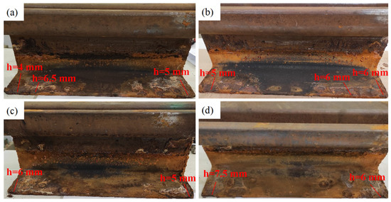
Figure 12.
Condition of the rails after testing was completed: (a) ZG 3/2, (b) PPE, (c) DEPP, (d) Zagreb 21-CTT.
The dimensions of the rail base surface affected by corrosion and the depth of the corrosion damage were measured for each rail sample. For each corrosion damage point, the corrosion level was classified as follows:
- -
- Low corrosion level: thinning of the rail foot up to maximum 1 mm,
- -
- Medium corrosion level: thinning of the rail foot from 1 to 3 mm, and
- -
- High corrosion level: thinning of the rail foot of more than 3 mm.
The percentage of each corrosion level was calculated with respect to the total corrosion surface area of each rail sample, and the results are listed in Table 4. Samples with a high level of corrosion were classified as critical.
Table 4.
Levels of corrosion observed on the rails in all fastening system components.
4.2.2. Clips
For the PPE, DEPP, and Zagreb 21-CTT fastening systems, corrosion was observed at the lowest part of the clips. For the PPE fastening system, the maximum reduction in the clip cross section was from 13 mm to 5.5 mm. For the DEPP fastening system, the cross section of the clips decreased from 13 mm to 6.5 mm, and for the Zagreb 21-CTT fastening system, the current resulted in a reduction of the cross section from 13 mm to 9 mm. In the case of the ZG 3/2 fastening system, no corrosion was observed on the clips. However, severe corrosion deterioration was observed on the steel rib in direct contact with the clip. Therefore, it was assumed that the current flowed from the clip into the steel rib and from the steel rib into the electrolyte (water). Because the same type of deterioration was observed in both clips of each tested sample, the condition of one clip from each sample after the test was completed is shown in Figure 13. In addition, the condition of the steel rib after the completion of the test is shown for the ZG 3/2 fastening system.
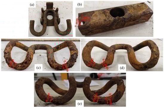
Figure 13.
Condition of clips and steel rib after testing was completed: (a) ZG 3/2-clip, (b) ZG 3/2- steel rib, (c) PPE, (d) DEPP, (e) Zagreb 21-CTT.
The percentage of cross-sectional thinning of the clips at the points of most severe clip degradation was calculated using the reference diameter and the diameter measured after completion of the laboratory test. Based on the corrosion percentage, the corrosion level was classified as follows:
- -
- Low corrosion level: cross-sectional thinning of up to 25%
- -
- Medium corrosion level: cross-sectional thinning of 25% to 50%
- -
- High corrosion level: cross-sectional thinning of more than 50%.
The reference height for all the clip types was 13 mm. The corrosion classification of the rail clips for all the test samples is presented in Table 5.
Table 5.
Corrosion level classification for the clips in all testing samples.
4.2.3. Steel Plate
After the samples were disassembled, a massive deterioration of the steel plate at the edges was also noted. The conditions of the steel plate after the completion of the test are shown in Figure 14. The dimensions of the corroded areas are defined for each steel plate.
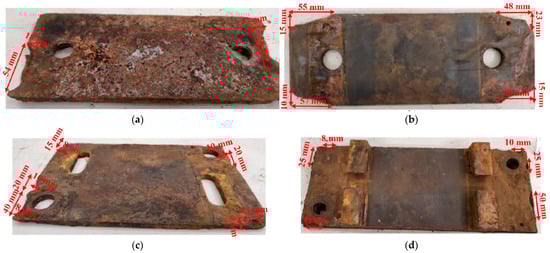
Figure 14.
Condition of the steel plate after testing was completed: (a) ZG 3/2, (b) PPE, (c) DEPP, and (d) Zagreb 21-CTT.
Corrosion of the steel plate was detected at the edge of the plate for all test samples. The percentage of corroded surfaces was calculated for each test sample (Table 6). Owing to the large dimensions of the plate, the corroded area was very small. Thus, the corrosion was classified as follows:
Table 6.
Corrosion level classification for the steel plates in all testing samples.
- -
- Low corrosion level: from 0.00% to 1.99% of corroded area
- -
- Medium corrosion level: from 2.00% to 3.99% of corroded area
- -
- High corrosion level: more than 4.00% of corroded area.
4.2.4. Anchor Bolts
The conditions of the anchor bolts were also analyzed after the completion of the test. Corrosion was observed on the parts of the anchors that were in contact with concrete. Figure 15 shows the condition of one anchor from each sample after completion of the test.
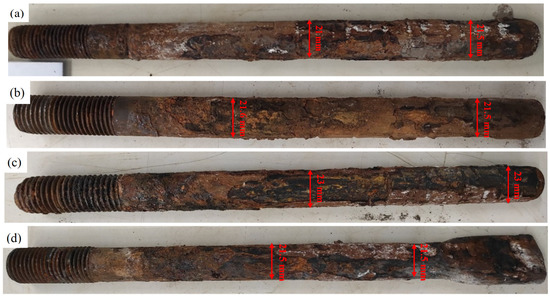
Figure 15.
Condition of the anchor bolts after testing was completed: (a) ZG 3/2, (b) PPE, (c) DEPP, and (d) Zagreb 21-CTT.
Because the anchor bolts are built in concrete, in addition to the corrosion area and thinning of the anchor cross section, the cracks observed in the leveling layer and in the concrete base (Figure 11) are also considered for the corrosion classification. The percentage of anchor bolt diameter thinning was calculated for all samples, as listed in Table 7. The corrosion damage was classified as follows:
Table 7.
Corrosion level classification for anchor bolts in all testing samples.
- -
- Low corrosion level: corroded surface up to 10%, small cracks in the concrete, no cross-sectional thinning of the anchor bolt
- -
- Medium corrosion level: corroded surface from 10 to 20%, small or medium cracks in the concrete, cross-sectional thinning up to 0.5 mm, and
- -
- High corrosion level: corroded surface of more than 20%, large or medium cracks in the concrete, cross-sectional thinning of 0.5 to 1 mm.
5. Discussion
When the samples were dried, the current leaked through the fastening system into the lower part of the track structure, and stray current corrosion occurred on the elements that were in contact with the concrete—i.e., anchor bolts and steel plate in the ZG 3/2 fastening system. In the ZG 3/2 and PPE fastening systems, the rails are in direct contact with the clip and anchor bolts, and the stray current depends only on the electrical resistance of the concrete layer. Under the immersed condition, corrosion started at the locations where the current allowed the metal elements to enter the electrolyte. The components of the fastening system in which corrosion occurred under different conditions are listed in Table 8.
Table 8.
Fastening system components on which corrosion occurs during testing in different conditions.
Although all the samples were immersed in water to half the height of the rail neck and exposed to the same DC current, no uniform deterioration of the fasteners was observed. Thinning of the rail foot cross section was observed in all fastening systems, but the highest level of deterioration was observed for ZG 3/2 and PPE. No clip deterioration was observed in the ZG 3/2 fastening system; however, severe corrosion was observed on the steel rib with which the clip was in direct contact. The most severe clip deterioration was observed in the PPE and DEPP fastening systems, whereas in the Zagreb 21-CTT fastening system, clip deterioration was not as pronounced. The steel base plate corroded in all the tested samples. Owing to their larger dimensions, the corrosion of the plate was not as pronounced in the DEPP and Zagreb 21-CTT fastening systems. From the performed corrosion classification, it can be concluded that in the tested samples, when the samples were immersed in water up to the middle of the height of the rail neck, a high level of corrosion was observed in the following components:
- -
- ZG 3/2 fastening system: rail, steel ribs, anchor bolts,
- -
- PPE fastening system: rail, clip SKL-1 (1), steel plate, and anchor bolts.
- -
- DEPP fastening system: clip SKL-1 (2), anchor bolt,
- -
- Zagreb 21-CTT fastening system: only medium level of corrosion on the clip SKL-12 (2).
This deterioration is a result of the current leaving the components of the fastening system and entering water or concrete.
6. Conclusions
For tracks with discretely fastened rails, the fastening points are “discharge points” for the current from the rail to the ground. Therefore, by better insulating the fastening system and ensuring adequate track drainage in a track asphalted into a car-running surface, stray current can be prevented. Despite the significant damage caused by stray currents to the rail and the components of the fastening system, insufficient attention has been paid to the prevention of stray currents. Moreover, the prevention of stray currents is not one of the characteristics that a fastening system must satisfy. The experiments described in this paper have shown that, to prevent stray current corrosion in the track, it is essential to provide adequate drainage so that water does not remain in the track. Under dry conditions, indirect fastening systems with insulated anchor bolts should be used to prevent stray currents. In addition, the elastomeric components of fastening systems must have high electrical resistivity, which was not the case for the fastening systems tested in this study. When direct fastening systems are used, an elastomeric pad should be installed between the rail foot and clip to prevent direct contact between them.
Stray currents can be significantly reduced by modifying the existing fastening systems in tracks with discretely fastened rails and by improving track maintenance. In addition to reducing stray currents and preventing harmful corrosion degradation of rails and fastening system components, modifying existing fastening systems can also improve ride comfort and reduce high levels of rail traffic noise and vibration.
Author Contributions
Investigation, K.V., S.L. and M.S.; Methodology, K.V. and M.S.; Project Administration, S.L.; Data Analysis, K.V. and M.S.; Supervision, S.L.; Writing-original draft, K.V.; Writing-review and editing, K.V., M.S. and S.L. All authors have read and agreed to the published version of the manuscript.
Funding
This research received no external funding.
Institutional Review Board Statement
Not applicable.
Informed Consent Statement
Not applicable.
Data Availability Statement
Not applicable.
Acknowledgments
The authors would like to thank Zagreb Electric Tram for providing the rail samples and components of the fastening systems used for the laboratory tests. We thank Beton Lučko and GTM for their assistance in preparing the test samples.
Conflicts of Interest
The authors declare that they have no competing financial interests or personal relationships that may have influenced the work reported in this article.
References
- Zhao, L.P.; Hua, L.J.; Liu, M.J. Simulation and Analysis of Metro Stray Current Based on Multi-Locomotives Condition. In Proceedings of the Chinese Control Conference, Chengdu, China, 27–29 July 2016; pp. 9252–9258. [Google Scholar]
- Zhiguang, C.; Chaokui, Q.; Jixu, T.; Yu, Z. Analysing of Stray Current Interference on Buried Gas Pipeline from Shanghai Urban Rail Transit. Res. J. Appl. Sci. Eng. Technol. 2013, 5, 4421–4426. [Google Scholar] [CrossRef]
- Vranešić, K.; Serdar, M.; Lakušić, S.; Kolar, V.; Mariscotti, A. Dynamic stray current measuring methods in urban areas. Balt. J. Road Bridge Eng. 2022, 17, 146–170. [Google Scholar] [CrossRef]
- Du, G.; Zhang, D.; Li, G.; Wang, C.; Liu, J. Evaluation of Rail Potential Based on Power Distribution in DC Traction Power Systems. Energies 2016, 9, 729. [Google Scholar] [CrossRef]
- Yang, X.; Xue, H.; Wang, H.; Zheng, Q.T. Stray Current and Rail Potential Simulation System for Urban Rail Transit. In Proceedings of the 2018 IEEE International Power Electronics and Application Conference and Exposition, (PEAC), Shenzhen, China, 4–7 November 2018. [Google Scholar]
- Lin, Y.; Li, K.; Su, M.; Meng, Y. Research on stray current distribution of Metro based on Numerical Simulation. In Proceedings of the IEEE International Symposium on Electromagnetic Compatibility and 2018 IEEE Asia-Pacific Symposium on Electromagnetic Compatibility (EMC/APEMC), Singapore, 14–18 May 2018; pp. 36–40. [Google Scholar]
- Liu, W.; Zhou, L.; Pan, Z.; Bhatti, A.A.; Huang, X.; Zhang, J. Dynamic Diffusion Model of Stray Current in DC Traction Power Supply System. IEEE Trans. Power Deliv. 2023, 1–11. [Google Scholar] [CrossRef]
- Vranešić, K.; Lakušić, S.; Serdar, M. Corrosion and Stray Currents at Urban Track Infrastructure. Građevinar 2020, 72, 593–606. [Google Scholar]
- Zaboli, A.; Vahidi, B.; Yousefi, S.; Hosseini-Biyouki, M.M. Evaluation and Control of Stray Current in DC-Electrified Railway Systems. IEEE Trans. Veh. Technol. 2017, 66, 974–980. [Google Scholar] [CrossRef]
- Kang, S.J.; Hong, M.S.; Kim, J.G. Method for Mitigating Stray Current Corrosion in Buried Pipelines Using Calcareous Deposits. Materials 2021, 14, 7905. [Google Scholar] [CrossRef]
- Zhang, J.; Song, X.; Xiao, L.; Chen, L.; Wu, G.; Cui, Y.; Lai, Z.; Li, Q. Simulation Study of the Influence of Stray Current on DC Bias of Power Transformer. J. Phys. Conf. Ser. 2020, 1626, 012061. [Google Scholar] [CrossRef]
- Chen, Z.; Koleva, D. Corrosion Behavior of Reinforcing Steel Undergoing Stray Current and Anodic Polarization. Materials 2021, 14, 261. [Google Scholar] [CrossRef]
- Flounders, E.; Memon, S. Stray Current Control of Direct Current-Powered Rail Transit Systems: A Guidebook Stray Current Control of Direct Current-Powered Rail Transit Systems: A Guidebook. 2020. Available online: https://nap.nationalacademies.org/read/25768/chapter/1 (accessed on 1 February 2023).
- Barlo, T.J.; Zdunek, A.D. Stray Current Corrosion in Electrified Rail Systems—Final Report. 1995. Available online: https://rosap.ntl.bts.gov/view/dot/13213 (accessed on 15 February 2023).
- Bertolini, L.; Carsana, M.; Pedeferri, P. Corrosion Behavior of Steel in Concrete in the Presence of Stray Current. Corros. Sci. 2007, 49, 1056–1068. [Google Scholar] [CrossRef]
- Lucca, G. Evaluating Stray Current Interference from DC Traction Lines on a Pipeline Network by Means of a Stochastic Approach. Electr. Eng. 2020, 103, 417–428. [Google Scholar] [CrossRef]
- Charalambous, C.A. Stray Current Control and Corrosion for DC Mass Transit Systems. Ph.D. Thesis, University of Manchester, Manchester, UK, 2005. [Google Scholar]
- Chuchit, T.; Kulworawanichpon, T. Stray Current Assessment for DC Transit Systems Based on Modelling of Earthing and Bonding. Electr. Eng. 2019, 101, 81–90. [Google Scholar] [CrossRef]
- Zare, J.; Ebrahim, R.K.; Niasati, M. Voltage Distribution Indices Method to Analyse the Performance of Various Structures of Stray Current Collectors in Direct Current Transit Lines. IET Electr. Syst. Transp. 2021, 11, 322–332. [Google Scholar] [CrossRef]
- Ogunsola, A.; Mariscotti, A.; Sandrolini, L. Estimation of Stray Current from a DC-Electrified Railway and Impressed Potential on a Buried Pipe. IEEE Trans. Power Deliv. 2012, 27, 2238–2246. [Google Scholar] [CrossRef]
- Chen, Z.; Koleva, D.; Breugel, K. A Review on Stray Current-Induced Steel Corrosion in Infrastructure. Corros. Rev. 2017, 35, 397–423. [Google Scholar] [CrossRef]
- Zhang, Y.; Feng, Q.; Hana, X.; Yu, L.; Wu, L.C.; Ng, S.; Tang, X. Numerical Modelling of Buried Pipelines under DC Stray Current Corrosion. J. Electrochem. Sci. Eng. 2019, 9, 125–134. [Google Scholar] [CrossRef]
- Zhu, Q.; Cao, A.; Zaifend, W.; Song, J.; Shengi, C. Stray Current Corrosion in Buried Pipeline. Anti-Corros. Methods Mater. 2011, 58, 234–237. [Google Scholar] [CrossRef]
- Machczynski, W.; Budnik, K.; Szymenderski, J. Assessment of D.C. Traction Stray Currents Effects on Nearby Pipelines. COMPEL—Int. J. Comput. Math. Electr. Electron. Eng. 2016, 35, 1468–1477. [Google Scholar] [CrossRef]
- Qin, H.; Zhang, T.; Du, Y.; Zhang, L.; Zhang, Y.; Liu, H. Experimental Study of Dynamic DC Stray Current Corrosion of X70 Steel. Mater. Corros. 2023, 74, 33–52. [Google Scholar] [CrossRef]
- Wang, C.; Li, W.; Wang, Y.; Xu, S.; Fan, M. Stray Current Distributing Model in the Subway System: A Review and Outlook. Int. J. Electrochem. Sci. 2018, 13, 1700–1727. [Google Scholar] [CrossRef]
- Juybari, E.Z.; Gholami, A. Evaluation of Ground Systems Performance on Rail Potential and Stray Current in Tehran Railway System. J. Model. Simul. Electr. Electron. Eng. 2022, 1, 43–49. [Google Scholar]
- Xu, W.; Zhang, B.; Deng, Y.; Wang, Z.; Jiang, Q.; Yang, L.; Zhang, J. Corrosion of Rail Tracks and Their Protection. Corros. Rev. 2021, 39, 1–13. [Google Scholar] [CrossRef]
- Safa, M.; Sabet, A.; Ghahremani, K.; Haas, C.; Walbridge, S. Rail Corrosion Forensics Using 3D Imaging and Finite Element Analysis. Int. J. Rail Transp. 2015, 3, 164–178. [Google Scholar] [CrossRef]
- Robles Hernández, F.C.; Plascencia, G.; Koch, K. Rail Base Corrosion Problem for North American Transit Systems. Eng. Fail. Anal. 2009, 16, 281–294. [Google Scholar] [CrossRef]
- Isozaki, H.; Oosawa, J.; Kawano, Y.; Hirasawa, R.; Kubota, S.; Konishi, S. Measures Against Electrolytic Rail Corrosion in Tokyo Metro Subway Tunnels. Procedia Eng. 2016, 165, 583–592. [Google Scholar] [CrossRef]
- Panda, B.; Balasubramaniam, R.; Dwivedi, G. On the Corrosion Behavior of Novel High Carbon Rail Steels in Simulated Cyclic Wet-Dry Salt Fog Conditions. Corros. Sci. 2008, 50, 1684–1692. [Google Scholar] [CrossRef]
- Li, Y.; Jiao, M.; Wang, Y.; Li, W.; Kang, H.; Zhang, W. Effect of Soil Salt Content on Stray Current Corrosion of Buried Metal. IEEE Access 2022, 10, 85843–85853. [Google Scholar] [CrossRef]
- Charalambous, C.A. Comprehensive Modelling to Allow Informed Calculation of DC Traction Systems’ Stray Current Levels. IEEE Trans. Veh. Technol. 2017, 66, 9667–9677. [Google Scholar] [CrossRef]
- Yu, H.; Liu, W.; Wang, P. Research on Stray Current and Rail-to-Earth Resistance in Traction Supply System. In Proceedings of the IEEE Transportation Electrification Conference and Expo, Asia-Pacific, Harbin, China, 7–10 August 2017. [Google Scholar]
- Lin, S.; Zhang, J.; Liu, X.; Zhang, X.; Cai, Z.; Chen, X. Study on Distribution Characteristics of Metro Stray Current and Evaluation of Cumulative Corrosion Effect. Adv. Civ. Eng. 2022, 2022, 6845847. [Google Scholar] [CrossRef]
- Aatif, S.; Hu, H.; Rafiq, F.; He, Z. Analysis of rail potential and stray current in MVDC railway electrification system. Railw. Eng. Sci. 2021, 29, 394–407. [Google Scholar] [CrossRef]
- Xiao, N.; Liu, J.; Wu, J.; Zeng, H.; Tan, Z.; Zeng, P.; Niu, W.; Chen, P.; Huang, H.; Xu, K.; et al. Analysis on Rail Potential Distribution Characteristics Considering OVPD in Metro System. IEEE Access 2021, 9, 141295–141306. [Google Scholar] [CrossRef]
- Mariscotti, A. Stray Current Protection and Monitoring Systems: Characteristic Quantities, Assessment of Performance and Verification. Sensors 2020, 20, 6610. [Google Scholar] [CrossRef]
- Mujezinović, A.; Martinez, S.; Kekez, K. Estimating harmful effect of dynamic stray currents on pipeline by simultaneous multiparametric field measurements, continuous wavelet cross-correlation analysis, and frequency plots. Mater. Corros. 2018, 70, 357–365. [Google Scholar] [CrossRef]
- EN_50122-2_2022; Railway Applications—Fixed Installations—Electrical Safety, Earthing and the Return Circuit—Part 2: Provisions against the Effects of Stray Currents Caused by DC Traction Systems. CENELEC: Brussels, Belgium, 2022.
- Saud, M.; Fromme, P. Stray-Current Corrosion and Mitigation. IEEE Electrif. Mag. 2014, 2, 22–31. [Google Scholar]
- Nouri, H.; Jamali, S.; Alamuti, M.M. Effects of Earthing Systems on Stray Current for Corrosion and Safety Behaviour in Practical Metro Systems. IET Electr. Syst. Transp. 2011, 1, 69–79. [Google Scholar]
- Mariscotti, A. Impact of Rail Impedance Intrinsic Variability on Railway System Operation, EMC and Safety. Int. J. Electr. Comput. Eng. 2021, 11, 17–26. [Google Scholar] [CrossRef]
- Baniček, M.; Uroš, M.; Lakušić, S. Development of a New and Modification of Existing Elastic Clips for Rails Fastening. Građevinar 2022, 74, 503–517. [Google Scholar]
- Mariscotti, A.; Pozzobon, P. Resistance and Internal Inductance of Traction Rails at Power Frequency: A Survey. IEEE Trans. Veh. Technol. 2004, 53, 1069–1075. [Google Scholar] [CrossRef]
- Niasati, M.; Gholami, A. Overview of Stray Current Control in DC Railway Systems. In Proceedings of the IET International Conference on Railway Engineering 2008 (ICRE 2008), Hong Kong, China, 25–28 March 2008; pp. 237–242. [Google Scholar]
- Lakušić, S.; Haladin, I.; Ahac, A. The Effect of Rail Fastening System Modifications on Tram Traffic Noise and Vibration. Shock. Vib. 2016, 2016, 4671302. [Google Scholar] [CrossRef]
- Central Corridor Light Rail Transit Report for Design Criteria. 2008. Available online: https://metrocouncil.org/Transportation/Publications-And-Resources/Transit/LIGHT-RAIL/Central-Corridor-Light-Rail-Transit-Design-Criteri.aspx (accessed on 8 February 2023).
- Valley Metro. Light Rail Transit Projects LRT Design Criteria Manual. 2020. Available online: https://drupal-space.nyc3.cdn.digitaloceanspaces.com/s3fs-public/uploads/event-resources/valley_metro_design_criteria_may_2020_0.pdf (accessed on 4 May 2023).
- Vranešić, K. Impact of Stray Currents on Rail Fastening Components in Urban Areas. Ph.D. Thesis, University of Zagreb, Faculty of Civil Engineering, Zagreb, Croatia, 2022. [Google Scholar]
Disclaimer/Publisher’s Note: The statements, opinions and data contained in all publications are solely those of the individual author(s) and contributor(s) and not of MDPI and/or the editor(s). MDPI and/or the editor(s) disclaim responsibility for any injury to people or property resulting from any ideas, methods, instructions or products referred to in the content. |
© 2023 by the authors. Licensee MDPI, Basel, Switzerland. This article is an open access article distributed under the terms and conditions of the Creative Commons Attribution (CC BY) license (https://creativecommons.org/licenses/by/4.0/).