Abstract
Background: The treatment of abdominal aortic aneurysm (AAA) is today commonly treated by inserting a stent-graft by the endovascular route, without resorting to open surgery. However, some clinical cases do not allow this less invasive approach, meaning that the stent-graft cannot be inserted and open surgery is used. Methods: In the study, we propose a fluid–structure interaction (FSI) analysis of an aneurysmatic aorta that could not be treated with Endovascular Aneurysm Repair (EVAR). The vessel is reconstructed through segmentation from CT scans and subsequently modeled on CAD software to create the surface and thickness of the vessel itself. Subsequently, we proceeded to carry out Computational Fluid Dynamics (CFD) and FSI simulation. We propose a computational study on a vessel geometry that is faithful to reality and customized. Results: Hemodynamic variable results of the carried out simulations indicate that low velocity and consequently very low WSS areas located in aneurysmal site are no longer found when conventional or patient-specific grafts are inserted. The wall stress distribution of aorta FEM analysis enabled the identification of the area at risk of failure, that is, in the posterior part of the aneurysm (∼ Pa), while FSI analysis of the patient-specific graft led to a uniform von Mises stresses distribution (∼ Pa), except for the junctions where peak stress occurred. Conclusion: The importance of this study is to highlight the benefits of the personalized stent/graft. As the authors expected, the study shows the numerous benefits of the customized stent/graft in terms of blood flow trend and wall stress compared to a traditional stent/graft by supporting the tendency to want to shift the target towards customized stents/grafts, also in the vascular surgery sector.
1. Introduction
An abdominal aortic aneurysm is a degeneration of the aorta that progressively enlarges, usually assuming a swollen fusiform shape. It is a permanent dilatation, which is pathological when the diameter increases by 50% compared to the diameter of the vessel in physiological conditions [1,2]. The risk of AAAs increases after 60 years of age with a major incidence in men (four to six times more common in men than in women [3]). The risk factors that affect the formation of the aneurysm are different. They can be divided into external factors and genetic factors. The external factors are smoking, obesity, existing heart disease, hypertension, and arteriosclerosis. Genetic factors, on the other hand, are linked to the heredity of the pathology, and more precisely to the internal arrangement and composition of the aortic tissue (collagen fibers). When the aneurysm exceeds 5 cm in diameter, surgical intervention becomes necessary. The walls of the aneurysmal vessel are subject to failure due to progressive damage to the tissue in the area of the aneurysm. The aneurysm can rupture, or rather the dissection of the aorta occurs; consequently, an internal hemorrhage occurs in the patient, which in a few minutes leads to death [4] From a purely mechanical point of view, the rupture of an AAA occurs when the mechanical stresses (internal forces per unit area) acting on the aneurysm exceeds the ability of the wall tissue to withstand these stresses (i.e., the wall’s failure strength). Among the innumerable parameters that can be considered and compared, wall shear stress is the one that has been used for the longest time and in the largest number of studies [2,3,4]. This indicator takes into account the combined effect of geometry, blood pressure, and the interaction between the fluid and solid domains. The surgical options for aneurysm treatment include the conventional Open Surgical Repair (OSR) and Endovascular Aneurysm Repair (EVAR). OSR is an invasive procedure that consists of a large incision at the site of the aneurysm, which is removed and replaced by a synthetic graft. Open repair is considered a good option for patients at a young age, with complications, severe co-morbidities, aortic dissection, or aneurysm rupture. It has limited use due to worse outcomes in terms of periand post-procedural mortalities and morbidities. On the other hand, EVAR is a minimally invasive procedure for the patient. It involves the release of a stent-graft introduced via a catheter into the patient’s femoral artery at the site of the aneurysm. The limit of EVAR treatment is linked to the morphology of the patient’s aorta, in particular the aspect linked to the curvature. Hostile behavior of the aortic neck is defined by its size, length, pulsatility, and thrombus and calcification lining. Generally speaking, the anatomical determinations that must be made in planning graft implantation are as follows:
- Diameter and length of the infrarenal aorta and neck of the aorta,
- Diameter and length of the iliac attachments,
- Tortuosity and size of the access vessels, and
- Critical vessel anatomy.
Criteria of eligibility for EVAR are as follows:
- Neck length ≥ 15 mm,
- Neck diameter < 30 mm,
- Neck angulation < 60–80 degrees, and
- Iliac diameter ≤ 7 mm.
The stent-grafts present on the market and produced by multinationals are standardized according to an array of measures that are adapted on the basis of the dimensions of the patient’s aorta and are customized as regards the position of the lateral ramifications if involved by the aneurysm, and in this case, these are the most sophisticated and expensive that the vascular surgeon has at their disposal. Customized stents/grafts, i.e., made to measure for the patient in terms of size and shape (curvature, diameter of the attachment area, etc.), are not currently produced and marketed. The presence of geometric interferences between the vessel and the endoprosthesis causes failure of the operation, for which the surgeon is forced to change from an EVAR to open surgery; other problems are linked to the duration of the stent-graft and post operative problems. Custom vascular stents represent the next generation of stents, which are able to accommodate the patient’s anatomical and vascular structure.
In this article, the authors have focused exclusively on the innovation linked to the customization of the stent/graft in terms of the curvature and dimensions of the local diameter of the rings. As far as the design of the metallic stent is concerned, the next step will be to optimize it for a potential increase in fatigue life related to the number of loops and the central bending angle [5,6]. Furthermore, given that such a thoughtful stent/graft requires a new production technology, in particular additive manufacturing, the design will have to be optimized also for this reason. The authors instead propose a stent-graft made for the specific morphology of the patient and therefore a total customization in terms of the shape of the endoprosthesis so that it can be inserted and correctly anchored via EVAR. The aneurysm size is the main parameter used today in clinical practice to evaluate the risk of rupture. Wall stress distribution is considered a better indicator of the AAA rupture risk in order to reduce the incident of rupture. A patient-specific study has demonstrated that the maximum wall stress was 12% more accurate and 13% more sensitive in predicting AAA rupture than the maximum diameter [7,8]. This parameter is influenced by the blood pressure, the aneurysm diameter, shape, wall thickness, wall mechanical properties, and the presence of thrombus. Several studies of AAA by means of computational models have been reported in the literature [7,9,10,11,12,13,14,15,16,17,18,19], each of which considerably simplifies the geometry of the vessel and of the aneurysm, without reporting a study carried out on a reconstruction of the aneurysmal vessel from a CT scan. Over the years, Computational Fluid Dynamics (CFD) analysis and, in the last decade, fluid–structure interaction (FSI) have been used to simulate the complex cardiovascular system. FSI offers a more accurate representation of the in vivo environment and is of major benefit as both graft and aneurysm wall stresses as well as fluid forces can be determined. Models based on idealized geometries and, more recently, patient-specific models have been used to study the mechanical characteristics of the aneurysm, also evaluating the influence of size, boundary conditions, or constitutive properties. In this paper, a patient-specific case of an abdominal aortic aneurysm was studied. Computational analyses were implemented on the patient-specific model of an abdominal aortic aneurysm and its customized stent graft. Hemodynamic parameters such as flow pattern, pressure, and wall shear stresses are highlighted to evaluate the benefits of using a patient-specific stent-graft.
2. Materials and Methods
In this study, the authors focus on the behavior of the stent-graft in conjunction with the blood streamlines crossing the aortic segment replaced by the device. The analysis is conducted “in-silico” by means of virtualization methods of the physical domain into a digital model suitable for the application of numerical methods to forecast its biomechanical behavior.
Soft tissues are considered and modeled as fiber-reinforced tissue. In fact, these are tissues made up of a water-based matrix and a fibrous part. The matrix contains what is called a ground substance. The fibers are collagen fibers with a preferential orientation in some layers (usually, in the direction in which the stress acts and therefore the tissue works) and in other random orientations. These tissues have a hierarchical structure in which the collagen fibers are in turn made up of fibrils. This particular hierarchical structure and the presence of the water-based matrix guarantee the tissue its mechanical characteristics, which guarantee that it will work in large deformations assuming a deformation even double that of the initial one [13].
In particular, this tissue has to be modeled as a viscoelastic and incompressible tissue with nonlinear stress–strain behavior. In the literature, several models are proposed that are more or less simplified and which take into account the single aspects; only some models take these aspects into account at the same time. The most comprehensive and most widely used model to describe aortic tissue response is the Holzapfel model. In this model, the arteries are incompressible bodies and differentiate two layers of cylindrical walls and as fibro-reinforced material. In particular, each layer is represented by separating two components, the isotropic extracellular matrix and the helical arranged collagen fibers, with different orientations for each layer. In the two-layer model, the media and the adventitia were modeled with the same energy function but with different parameters. Subsequently, the model was refined considering a single overall layer of the wall that took into account the average comprehensive characteristics, and a fiber dispersion parameter was introduced with respect to the mean direction.
Preliminary analysis involved the reconstruction of a patient’s aortic vessel by means of virtualization tools such as those provided by the commercial software MIMICS (Materialise). This allows for a precise morphological description of the vessel, but, in order to smooth the internal and external surfaces, a third-order digital filter that regularizes the surface has been used. The biomechanical analysis of the vessels has been conducted in terms of CFD and FEM to obtain the hemodynamic streamlines as well as the strain, stresses, and displacement of the aortic vessel.
Hemodynamics with conventional grafts used in open surgery and the considered patient-specific stent-graft have been reported in terms of CFD numerical analysis for comparison’s sake.
The biomechanics of the patient-specific stent-graft was further deepened by means of fluid–structural interaction (FSI) analysis considering at each computational time step the changes in the configuration of the stent-grafts induced by the variation of the stress in the fluid domain.
The virtual model considered involves the abdominal aorta of the examined patient, the graft modeled on the patient’s vessel, and the metal reinforcing struts represented by a shape memory Ni-Ti alloy known conventionally as NiTinol. The authors modeled each of these elements with the aim of carrying out CFD analysis of the vessel, FEM analysis of the vessel, and fluid structure analysis of the customized graft compared to the traditional graft.
The vessel of the abdominal aorta has been demonstrated to be an hereditary tissue with time-dependent properties [20,21,22,23,24,25,26,27,28,29,30,31,32,33,34,35,36,37,38,39,40,41,42,43,44,45]. Despite this important issue, very few contributions in scientific literature involve virtual models of the aortic tissues endowed with material hereditariness. The mainly used representation of the material mechanics is represented by a hyperelastic model [38] with free energy density, defined in terms of the strain tensor invariants, as in the Neo-Hookean, Ogden-Holzapfel, or more sophisticated materials models. In the present analysis, the FEM simulations have been carried out with the Neo-Hookean [46,47] model for the aortic tissue, and it was implemented on ABAQUS (Dassàult systémes) to reduce computational cost and, at the same time, to improve the accuracy of the simulation.
The biomechanical characteristics of the patient-specific stent-graft involve two materials, one for the graft and the other for the stent: (i) the graft is the envelope of the device that represents the new lumen of the vessel, and that is constituted by a DACRON or polytetrafluoroethylene (PTFE) polymer, and (ii) the stent is composed of the stiffening struts, pre-knitted on the graft, which are represented by metallic rings with a 3D sinusoidal structure. In this study, the graft material has considered as DACRON, and its mechanical characteristics have been included for FSI analysis. The metallic structure of the stent, instead, has been considered to be constituted by Ni-Ti alloy. NiTinol is a shape memory alloy (SMA) that consists of an equiatomic amount of nickel and titanium. NiTinol is very popular in biomedical applications due to its remarkable super-elasticity, shape memory, biocompatibility, and corrosion resistance, as well as fatigue resistance and durability. NiTinol is a shape memory alloy that can be programmed to expand as soon as it is inserted into position and released, at a body temperature of 37 °C, assuming the dimensions of the vessel and remaining closed on itself at other temperatures; in this way, it is not necessary to use an expandable balloon to open the stent-graft once inserted. This represents the gold standard in cardiovascular applications.
A typical stress–strain diagram of a Ni-Ti superelastic alloy is represented in Figure 1.
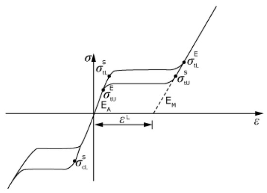
Figure 1.
Nitinol curve.
We started modeling from the CT images Figure 2 of the AAA patient. The images were imported using the segmentation software Mimics 21.0 (Materialise), which allowed the two-dimensional and then three-dimensional reconstruction of the patient’s aneurysm vessel Figure 3. Segmentation processes were applied both automatically and manually. Automatic operation was used to select the region of interest. These operations were based on the gray-scale of the CT images. The manual segmentation was then used to reduce the region of interest and to obtain an accurate mask. The accuracy of the vessel model therefore depended on the quality of the CT images, on the number of images available to the operator, and ultimately on the operator’s ability to improve these manually by intervening in the automatic reconstruction process.
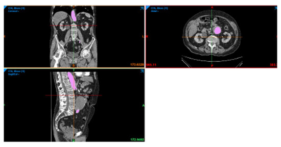
Figure 2.
CT image of the sagittal, axial, and coronal plane of the patient.
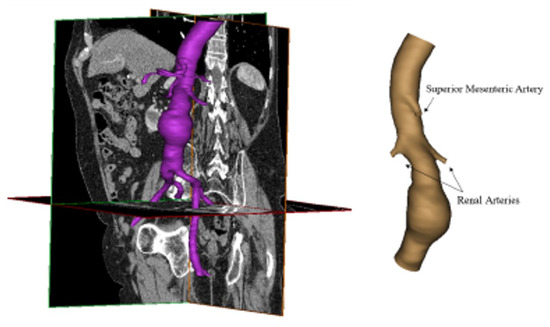
Figure 3.
Three-dimensional reconstruction of aneurismatic abdominal aorta.
The three-dimensional model of the patient’s aorta used in CFD analysis was reconstructed by Mimics. Based on this, the stent-graft was realized by SolidWorks (Dassault Systémes), as shown in Figure 4. The rings of the stent have a circular section, and their size adapts to the diameter of the graft. To perform CFD analyses, fluid models of the conventional graft and the patient-specific graft were also reconstructed using the software Soliworks, as shown in Figure 5. In detail, to reconstruct the conventional model, the graft was included in the aneurysm site. The three models were exported in .STL format for the next step.
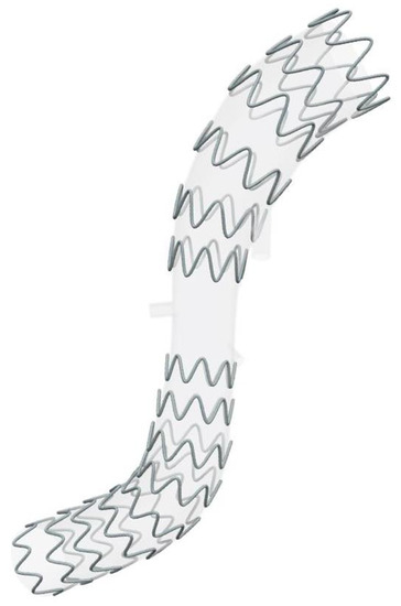
Figure 4.
Patient-specific stent-graft proposed by the authors.
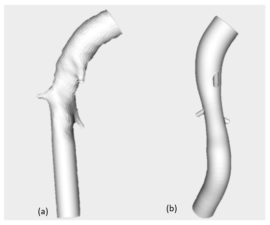
Figure 5.
Conventional graft (a) and patient-specific graft (b).
The governing equations are
In this study, the Eulerian approach has been adopted. The numerical method used to solve the non-linear coupled equations in the fluid region and in the vessel region involves a preliminary subdivision in a sequence of volumes of the tetrahedral shape of the two volumes. As the subdivision is provided, a linear approximation of the displacement and velocity fields in each discretized volume region has been introduced in the model depending explicitly on the values of the solutions at the corners of the tetrahedron. As the weak formulation of the governing equations has been enforced along the whole domain, the non-linear partial differential problem was formulated in terms of a non-linear ordinary differential problem. The solution has been obtained by means of the implicit Runge–Kutta method introducing a fourth-order polynomial description of the acceleration in each time step. The progressive reduction of time step intervals was involved as a preselected tolerance was not reached in each time step. The three fluid models (i.e., aneurismatic aorta, conventional, and patient-specific graft) were imported in .STL format in ICEM CFD 19.2 (Ansys Inc.) to discretize the volume in small elements and realize the mesh. For each model, tetrahedral elements in the core region and prismatic elements in the boundary layer (3 layers) were used. The created mesh consisted of about 1 million elements, as shown in Figure 6. Mesh quality was acceptable, and a verification operation was also performed in order to eliminate the unconnected vertices.
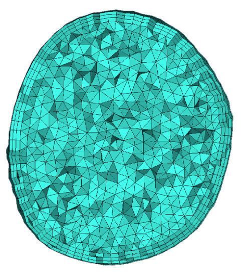
Figure 6.
Mesh of the aortic vessel.
Fluid dynamics was evaluated by a transient CFD simulation performed using FLUENT v19.2 (Ansys Inc.). A CFD solver was used to obtain an approximate solution of the Navier–Stokes differential equation that governs the fluid flow. The assumption and the analysis set-up were the same for the three fluid models (aneurismatic aorta, conventional, and patient-specific grafts). The blood flow was assumed to be compressible and Newtonian with a density of 1060 and viscosity of 0.003 . With a diameter greater than 0.5 , an assumption of Newtonian flow through the aorta is reasonable due to the fact that blood viscosity is relatively constant at the high rates of shear (100/s) typically found in the aorta [48]. The pressure velocity coupling algorithm SIMPLE was used as a solution method, and residuals in the order of have been fixed for equation convergence. Six boundary surfaces were defined in all three fluid models; in particular, the inlet, four outlets: abdominal, branch1, branch2 and Mesenteric, and the wall.
The boundary conditions used for the model are time-dependent. The velocity inlet boundary conditions were taken from color Doppler measurements of the aortic blood average velocity, previously adopted by [48]. Pressure outlet conditions were based on [49], in which branch pressure waveforms were assumed to follow the aorta waveform with scale down amplitudes, following Chong et al. [50]. A velocity profile [51] for inlet and pressure [49] at outlet surfaces was imposed. The mixed-type boundary condition represents physiological conditions more accurately because when the heart ventricles contract, it induces a change in volume that causes a pressure gradient and forces the blood out [52]. A no-slip condition was assumed at the wall. Below, we present the velocity in Figure 7a and the different pressure profiles in Figure 7c,d fixed as boundary conditions. Two cardiac cycles have been simulated in order to achieve a solution that is independent of the initial conditions.
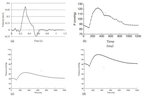
Figure 7.
(a) Velocity inlet profile; (b) pressure profile at abdominal outlet; (c) pressure profile at mesenteric and branch1 outlets; (d) pressure profile at branch2.
Finite element analysis was performed to assess the stress of the aneurysm vessel wall using Abaqus v.6.14 (Dassault Systémes Inc.). The description of the analysis set-up followed the module of the software. The aorta wall was reconstructed from the patient’s three-dimensional model and imported in Abaqus in the Part Module. It was considered a shell; this assumption was appropriate because the thickness was significantly smaller than the other dimensions [10]. Shell elements allow the capture of highly tortuous (patient-specific) shapes that are more intricate with solid elements [53]. These were modeled according to the constitutive model of Neo-Hookean. One step was defined, which was a dynamic explicit step, and the step size was automatic. In the Load Module, load and boundary conditions were fixed; in particular, model inlet and outlets were constrained in all degrees of freedom. This constraint, though non-physiological—as the inlet and outlets should be allowed to deform radially to correctly simulate tethering of the artery—is commonly assumed in finite element studies of aneurysms [54]. As regards load, a pressure profile was applied to the shell inner surface. It was constructed on the basis of wall-averaged pressure values obtained from previous aneurysm CFD analysis.
Parallel-coupled one-way FSI analysis was performed using the commercial software MpCCI v4.6.1 (Fraunhofer SCAI). This is a software environment that enables the exchange of data between the mesh of two simulation codes in a multiphysics simulation. The coupling data can be set to Serial or Parallel. In this study, this software was used to couple the structural solver, Abaqus 2021 (Simulia Inc.), and the fluid solver, FLUENT v19.2 (ANSYS Inc.). The aortic wall was identified as a common boundary surface, and a parallel coupling scheme was used. The time step that defines the frequency of the data exchange between the two solvers was chosen in accordance with the cardiac cycle time. FSI analysis, even one-way data exchange, is very complex and time-consuming. The morphology and the structure of the aforementioned stent-graft are complicated; therefore, the fluid structure interaction was implemented on the patient-specific graft model without the stent. To evaluate the ring behavior under the load pressure during the cardiac cycle, a simple structural analysis was implemented.
The set-up of the fluid dynamics analysis is the same as described above. In brief:
- The blood flow was assumed incompressible and Newtonian with a density of 1060 and viscosity of 0.003 .
- The boundary surfaces defined were the inlet, the outlets, and the wall. A velocity profile [51] in inlet and pressure [49] at outlet surfaces was imposed (velocity and pressure profiles are in the figures). A no-slip condition was assumed at the wall.
As mentioned above, the structural analysis was run on Abaqus 2021. In the Part Module, the graft geometry was imported. It is a solid model with a thickness of 0.7 mm and, for a correct coupling, the surface for exchange data was defined. The DACRON (density 1390 ) was modeled as an elastic linear material with a Young’s modulus of 3 GPa and Poisson’s coefficient of 0.35. One dynamic implicit step time was defined, with a fixed increment of 0.0025 s. Two cardiac cycles were implemented for a total time of 2.4 s. As regards the Load Module, inlet and outlets were constrained in all degrees of freedom. To create the mesh, a global element size (1 mm) was first defined, and then at critical point, such as branches, a local element size was defined (0.5 mm). In addition, along the thickness, three layers of elements were created. The mesh consisted of 158,495 tetrahedral elements. In the Job Module, the file .inp was created for the co-simulation by MpCCI.
In the same way, the ring behaviors were also investigated. The ring geometry was imported into Abaqus 2021. NiTinol (6450 ) was modeled as a super-elastic material using the data and formulation of Auricchio and Taylor (1997) [55] repoted in Table 1. The parameter is shown in the following figure. One dynamic explicit step time was defined, with a fixed increment. In the inner surfaces—that is, in theory, the part of the rings in contact with the graft—a pressure profile Figure 8 was applied. In particular, it was obtained by extrapolating the wall-averaged pressure values from a previous aneurysm CFD analysis of a graft. Finally, in the Mesh Module, the rings were discretized with tetrahedral elements of 0.3 mm.

Table 1.
Nitinol parameters used in Abaqus.
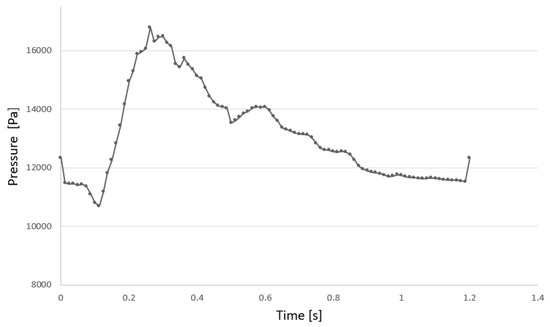
Figure 8.
Pressure profile applied to the shell inner surface.
3. Results
The authors have chosen to show the most significant results of this study, including the wall shear stress (WSS), pressure, velocity, and the flow pattern at the systole peak, which are the hemodynamic in-depth variables in all three fluid models in the CFD analyses.
Figure 9 shows the WSS in three fluid models. At the site of the aneurysm, the WSS is zero. This indicates that the blood flow does not exercise tangential stresses on the wall due to the presence of low-velocity areas in the site, as can be seen in Figure 9. The maximum WSS is in branches: in the conventional graft, it is 184.6 Pa, while it is 142 Pa in the patient-specific graft.
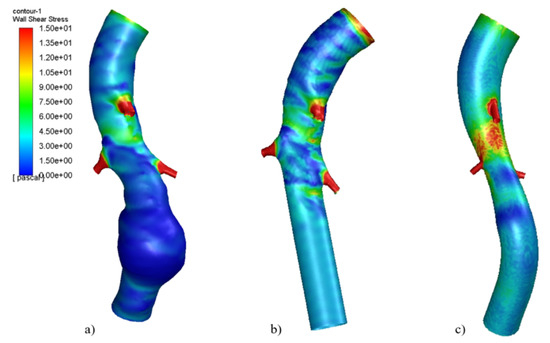
Figure 9.
Wall shear stress at systole peak in (a) Aneurismatic aorta, (b) conventional graft, (c) patient-specific graft.Reproduced with permission from S. Ragusa, K. Siciliano, F.P. Di Simone, S. Russotto, E. Bologna, M. Zingales, Theoretical and Applied Mechanics-Aimeta 2022; published by Centro Servizi d’Ateneo S.r.l., 2023.
The pressure distribution was also investigated, as shown in Figure 10. In all three models, peak values are comparable and cover the same area.
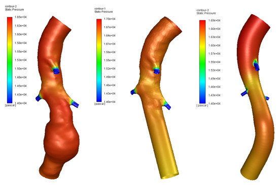
Figure 10.
Pressure in aneurysm site of three models.
As regards velocity, the use of both conventional and patient-specific grafts removes the low-velocity areas present in aneurismatic vessels, as shown in Figure 11 and Figure 12. Figure 13 shows the Von Mises stress of the graft surface at the systole peak (the solution of the fluid domain is the same as simple CFD analysis, and it was presented in more detail above).
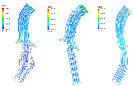
Figure 11.
Blood flow of three models.
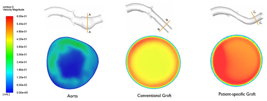
Figure 12.
Velocity in aneurysm site of three models. Reproduced with permission from S. Ragusa, K. Siciliano, F.P. Di Simone, S. Russotto, E. Bologna, M. Zingales, Theoretical and Applied Mechanics-Aimeta 2022; published by Centro Servizi d’Ateneo S.r.l., 2023.
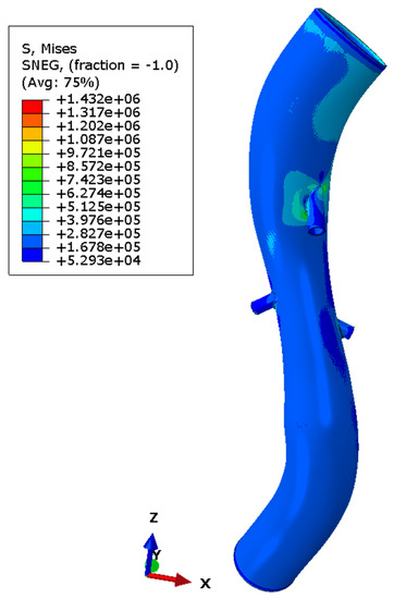
Figure 13.
Von Mises stress in graft model.
4. Discussion
The results obtained and presented in this work are only partially comparable with the literature on studies of aneurysms or endoprostheses [1,2,3,6,8,10,11], since the cases are dealt with separately or through the CFD study of the reconstructed aorta or the study of the stent/graft, which is always simplified at the level of geometry. The simplification on the geometry considering a perfectly tubular vessel with a straight axis and the stent/graft also allows faster analyses with less computational effort. The simplification of the modeling is therefore acceptable when one focuses on the study of the modeling of the aneurysm and its evolution, but not when the objective is, as in this work, to show the benefits of a personalized target prosthesis achieved by current medicine in the major fields of bioengineering and orthopedics neurosurgery, but still not reached in vascular surgery. The conducted CFD analyses have highlighted the advantages of using a patient-specific stent-graft. The wall shear stress (WSS), pressure, velocity, and the flow pattern at systole peak are the hemodynamic in-depth variables in all three fluid models in CFD analyses. In line with various studies in the literature [6,8,56,57], it is noted that the wall shear stress at the site of the aneurysm is zero. This indicates that the blood flow does not exert tangential stresses on the wall due to the presence of low-velocity areas in the site, as can be seen in Figure 12. The maximum WSS is in branches: in the conventional graft, it is 184.6 Pa, while it is 142 Pa in the patient-specific graft. The use of a patient-specific graft reduces the maximum WSS by about 23% to the vessel and exhibits a distribution of wall shear stress that is more uniform than other models. The flow pattern shown in the conventional graft is not yet in the regime condition, and it is very different to the flow pattern of a patient-specific graft. This aspect is associated to the morphology of the graft used; the patient-specific one accommodates the vessel morphology and does not alter the vascular physiology. As regard the maximum velocity, a value of 4.6 is reached in the patient-specific graft, while for the conventional graft, the value is 4.2 . Note that the use of grafts improves the pressure profile, at 17 kPa, but the curvatures are still complicated areas with high pressure values (in particular, in the patient-specific graft). The FEM analysis of the aortic wall provided a good and reliable overview of the wall stress distribution, as shown in Figure 14. Although the peak values are concentrated on the ramifications—areas of concentration of tension—it is interesting to note that at the level of the aneurysm, the posterior part is most compromised. The results obtained, although relating to dynamic and non-FSI analysis, allow us to visualize the main characteristics regarding the distribution of the wall stress and, therefore, the areas at risk of failure. On the other hand, the model used presents some simplifications, such as the absence of calcifications and ILT and the assumption of a uniform thickness and shell model, which influence the wall stress distribution and the pathogenesis of the aneurysm [10,58,59].
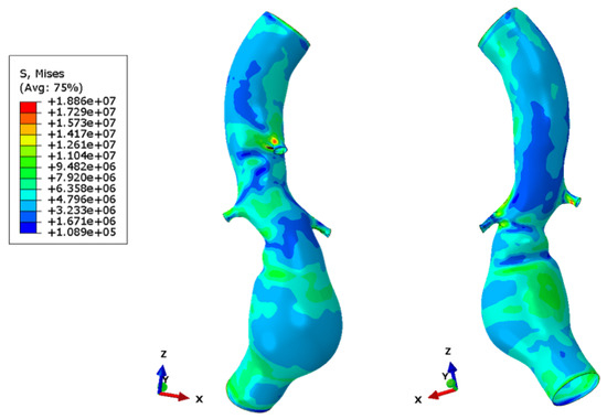
Figure 14.
Wall stress in aneurismatic aorta.
As already widely discussed, FSI analysis provides more accurate results by modeling situations similar to in vivo circumstances [56]. In fact, in this case, it allowed the evaluation of wall stress and pressure on the graft by subjecting it directly to the fluid dynamic condition of interest (one-way coupling). Higher values and the peaks are near to the mesenteric branch’s junction. This result is due to the birth of shape drag. The drag is the reason that the flow increases its kinetic energy, and therefore, in those areas, the flow becomes turbulent. For this reason, the geometry is the cause of the stress peaks. The same applies to the renal arteries, but the wall stress values are lower. The lack of a stent causes the DACRON to become excessively deformed. It is. crushed in the smaller diameter part, at the renal arteries, while expanding at the extremities. The presence of the rings gives greater stiffness to the material and prevents the crushing of the graft subjected to the pulsatile blood flow.
The conducted FSI has indeed highlighted the importance of targeted design. In general, and also in this case, the ramifications are zones of stress concentration; thus, it is necessary to act on the junction. This is further complicated by the complexity of the morphology, which is affected by important curvatures that make the treatment, the development of analysis, and the use of these computational methods difficult. A crucial aspect is the interaction between the stent and the graft. The interaction highlighted problems of gap and over-closure related to the curvature and morphology of the graft.
5. Conclusions
The actual issue that concerns the treatment of aneurysm is the development of patient-specific devices that can support the vascular structure of the individual, unlike the devices used today. The authors have developed and studied a customized endoprosthesis that requires a new delivery system to carry out the EVAR procedure and a new production technology to be implemented. For this reason, the preliminary study reported here investigated the actual benefits of using a personalized stent/graft.
The article’s findings show that the theorized benefit that the customized stent/graft for the treatment of AAA promised to deliver has lived up to expectations. In fact, the study on the endoprosthesis, both by observing the results of the CFD and by observing the FSI results, shows the goodness of the solution. This model can then be further implemented and enriched by the viscoelastic part, and the use of a complete hyperelastic model and the modeling of the presence of the strats will support the development of a new medical device. This confirms what was theorized, namely the possibility of extending the treatment in EVAR.
Author Contributions
Conceptualization, E.B., E.D., F.P. and M.Z.; methodology, K.S.; validation, E.B.; formal analysis, S.R.; writing—original draft preparation, E.B. and E.D.; writing—review and editing, E.B. and S.R.; visualization, F.D.S.; supervision, M.Z.; project administration, M.Z. All authors have read and agreed to the published version of the manuscript.
Funding
This research was funded by MUR, PNRR-M4C2, ECS-00000022.
Institutional Review Board Statement
All subjects gave their informed consent for inclusion before they participated in the study. The study was conducted in accordance with the Declaration of Helsinki, and the protocol was approved by the Ethics Committee of Policlinico Giaccone (n.1145).
Informed Consent Statement
Informed consent was obtained from all subjects involved in the study.
Data Availability Statement
To have access to the data from which the results were obtained, contact emanuela.bologna@unipa.it.
Acknowledgments
The authors are very grateful to the Advanced Medical Engineering Devices SRL, a subsiduary of University of Palermo. Emanuela Bologna thanks Francesco Di Simone and Katia Siciliano for the preliminary activity of this study. The authors thank Sicilian Micronanotech Research And Innovation Center “SAMOTHRACE” (MUR, PNRR-M4C2, ECS-00000022), spoke 3—Università degli Studi di Palermo “S 2-COMMs-Micro and Nanotechnologies for Smart and Sustainable Communities”.
Conflicts of Interest
The authors declare no conflict of interest.
References
- Erbel, R.; Aboyans, V.; Boileau, C.; Bossone, E.; Bartolomeo, R.D.; Kravchenko, I. ESC Guidelines on the diagnosis and treatment of aortic diseases: Document covering acute and chronic aortic diseases of the thoracic and abdominal aorta of the adult The Task Force for the Diagnosis and Treatment of Aortic Diseases of the European Society of Cardiology (ESC). Eur. Heart J. 2014, 35, 2873–2926. [Google Scholar] [PubMed]
- Daugherty, A.; Cassis, L.A. Mechanisms of abdominal aortic aneurysm formation. Curr. Atheroscler. Rep. 2002, 4, 222–227. [Google Scholar] [CrossRef] [PubMed]
- Aggarwal, S.; Qamar, A.; Sharma, V.; Sharma, A. Abdominal aortic aneurysm: A comprehensive review. Exp. Clin. Cardiol. 2002, 16, 11–15. [Google Scholar]
- Xenos, M.; Rambhia, S.H.; Alemu, Y.; Einav, S.; Labropoulos, N.; Tassiopoulos, A.; Bluestein, D. Patient-based abdominal aortic aneurysm rupture risk prediction with fluid structure interaction modeling. Ann. Biomed. Eng. 2010, 38, 3323–3337. [Google Scholar] [CrossRef]
- Alaimo, G.; Auricchio, F.; Conti, M.; Zingales, M. Multi-objective optimization of nitinol stent design. Med. Eng. Phys. 2017, 47, 13–24. [Google Scholar] [CrossRef]
- Wolters, B.J.B.M.; Rutten, M.C.M.; Schurink, G.W.H.; Kose, U.; de Hart, J.; van de Vosse, F.N. A patient-specific computational model of fluid–structure interaction in abdominal aortic aneurysms. Med. Eng. Phys. 2005, 871–883. [Google Scholar] [CrossRef]
- Fillinger, M.F.; Marra, S.P.; Raghavan, M.L.; Kennedy, F.E. Prediction of rupture risk in abdominal aortic aneurysm during observation: Wall stress versus diameter. J. Vasc. Surg. 2003, 37, 724–732. [Google Scholar] [CrossRef]
- Leung, J.H.; Wright, A.R.; Cheshire, N.; Crane, J.; Thom, S.A.; Hughes, A.D.; Xu, Y. Fluid structure interaction of patient specific abdominal aortic aneurysms: A comparison with solid stress models. Biomed. Eng. Online 2006, 5, 33. [Google Scholar] [CrossRef]
- Vorp, D.A.; Raghavan, M.L.; Webster, M.W. Mechanical wall stress in abdominal aortic aneurysm: Influence of diameter and asymmetry. J. Vasc. Surg. 1998, 27, 632–639. [Google Scholar] [CrossRef]
- Wang, D.H.; Makaroun, M.S.; Webster, M.W.; Vorp, D.A. Effect of intraluminal thrombus on wall stress in patient-specific models of abdominal aortic aneurysm. J. Vasc. Surg. 2002, 36, 598–604. [Google Scholar] [CrossRef]
- Jayendiran, R.; Nour, B.; Ruimi, A. Computational fluid–structure interaction analysis of blood flow on patient-specific reconstructed aortic anatomy and aneurysm treatment with Dacron graft. J. Fluids Struct. 2018, 81, 693–711. [Google Scholar] [CrossRef]
- Raghavan, M.L.; Vorp, D.A.; Federle, M.P.; Makaroun, M.S.; Webster, M.W. Wall stress distribution on three-dimensionally reconstructed models of human abdominal aortic aneurysm. J. Vasc. Surg. 2000, 31, 760–769. [Google Scholar] [CrossRef]
- Soudah, E.; Ng, E.Y.; Loong, T.H.; Bordone, M.; Pua, U.; Narayanan, S. CFD Modelling of Abdominal Aortic Aneurysm on Hemodynamic Loads Using a Realistic Geometry with CT. Comput. Math. Methods Med. 2013, 2013, 472564. [Google Scholar] [CrossRef]
- Stergiou, Y.G.; Kanaris, A.G.; Mouza, A.A.; Paras, S.V. Fluid-structure interaction in abdominal aortic aneurysms: Effect of haematocrit. Fluids 2019, 4, 11. [Google Scholar] [CrossRef]
- Lin, S.; Han, X.; Bi, Y.; Ju, S.; Gu, L. Fluid-structure interaction in abdominal aortic aneurysm: Effect of modeling techniques. BioMed Res. Int. 2017, 2017, 7023078. [Google Scholar] [CrossRef]
- Philip, N.T.; Patnaik, B.S.V.; Sudhir, B.J. Hemodynamic simulation of abdominal aortic aneurysm on idealised models: Investigation of stress parameters during disease progression. Comput. Methods Programs Biomed. 2021, 213, 106508. [Google Scholar] [CrossRef]
- Salman, H.E.; Yalcin, H.C. Computational Investigation of the Effect of Wall Thickness on Rupture Risk in Abdominal Aortic Aneurysms. J. Appl. Fluid Mech. 2021, 14, 499–513. [Google Scholar]
- Đorovic, S.; Filipovic, N. Computational analysis of abdominal aortic aneurysm before and after endovascular aneurysm repair. Comput. Model. Bioeng. Bioinform. 2019, 353. [Google Scholar]
- Li, Z.; Kleinstreuer, C. Blood flow and structure interactions in a stented abdominal aortic aneurysm model. Med. Eng. Phys. 2005, 27, 369–382. [Google Scholar] [CrossRef]
- Dinoto, E.; Mirabella, D.; Ferlito, F.; Tortomasi, G.; Turchino, D.; Evola, S.; Zingales, M.; Bologna, E.; Pecoraro, F. Carotid Artery Disease in the Era of Biomarkers: A Pilot Study. Diagnostics 2023, 13, 644. [Google Scholar] [CrossRef]
- Bologna, E.; Di Paola, M.; Zingales, M. Analysis of a Beck’s column over fractional-order restraints via extended Routh-Hurwitz theorem. In Modern Trends in Structural and Solid Mechanics 1: Statics and Stability; Challamel, N., Kaplunov, J., Takewaki, I., Eds.; John Wiley & Sons: Hoboken, NJ, USA, 2021; pp. 43–66. [Google Scholar]
- Alotta, G.; Bologna, E.; Zingales, M. Exact mechanical hierarchy of non-linear fractional-order hereditariness. Symmetry 2020, 12, 673. [Google Scholar] [CrossRef]
- Bologna, E.; Di Paola, M.; Zingales, M. A single integral approach to fractional order non-linear hereditariness. In Lecture Notes in Mechanical Engineering; Springer: Cham, Switzerland, 2020; pp. 932–944. [Google Scholar]
- Alotta, G.; Bologna, E.; Failla, G.; Zingales, M. A Fractional Approach to Non-Newtonian Blood Rheology in Capillary Vessels. J. Peridynamics Nonlocal Model. 2019, 1, 88–96. [Google Scholar] [CrossRef]
- Bologna, E.; Graziano, F.; Deseri, L.; Zingales, M. Power-Laws hereditariness of biomimetic ceramics for cranioplasty neurosurgery. Int. J. -Non-Linear Mech. 2019, 115, 61–67. [Google Scholar] [CrossRef]
- Camarda, L.; Bologna, E.; Pavan, D.; Morello, F.; Monachino, F.; Giacco, F.; Zingales, M. Posterior meniscal root repair: A biomechanical comparison between human and porcine menisci. Muscles Ligaments Tendons J. 2019, 9, 76–81. [Google Scholar] [CrossRef]
- De Caro, V.; Murgia, D.; Seidita, F.; Bologna, E.; Alotta, G.; Zingales, M.; Campisi, G. Enhanced in situ availability of Aphanizomenon Flos-Aquae constituents entrapped in buccal films for the treatment of oxidative stress-related oral diseases: Biomechanical characterization and in vitro/ex vivo evaluation. Pharmaceutics 2019, 11, 35. [Google Scholar] [CrossRef]
- Dintcheva, N.T.; Baiamonte, M.; Teresi, R.; Alotta, G.; Bologna, E.; Zingales, M. A Fractional-Order Model of Biopolyester Containing Naturally Occurring Compounds for Soil Stabilization. Adv. Mater. Sci. Eng. 2019, 2019, 5986564. [Google Scholar] [CrossRef]
- Alotta, G.; Bologna, E.; Di Giuseppe, M.; Zingales, M.; Dimitri, R.; Pinnola, F.P.; Zavarise, G. A Non-Local Mode-I Cohesive Model for Ascending Thoracic Aorta Dissections (ATAD). In Proceedings of the IEEE 4th International Forum on Research and Technologies for Society and Industry, RTSI 2018, Palermo, Italy, 10–13 September 2018; p. 8548349. [Google Scholar]
- Di Giuseppe, M.; Zingales, M.; Bologna, E.; Pasta, S.; Alotta, G. Hereditariness of Aortic Tissue: In-Vitro Time-Dependent Failure of Human and Porcine Specimens. In Proceedings of the IEEE 4th International Forum on Research and Technologies for Society and Industry, RTSI, Palermo, Italy, 10–13 September 2018; p. 8548387. [Google Scholar]
- Barrera, O.; Bologna, E.; Alotta, G.; Zingales, M. Experimental Characterization of the Human Meniscal Tissues. In Proceedings of the IEEE 4th International Forum on Research and Technologies for Society and Industry, RTSI, Palermo, Italy, 10–13 September 2018; p. 8548369. [Google Scholar]
- Bologna, E.; Zingales, M.; Alotta, G.; Deseri, L. Quasi-Fractional Models of Human Tendons Hereditariness. In Proceedings of the IEEE 4th International Forum on Research and Technologies for Society and Industry, RTSI, Palermo, Italy, 10–13 September 2018; p. 8548419. [Google Scholar]
- Bologna, E.; Zingales, M. Stability analysis of beck’s column over a fractional-order hereditary foundation. Proc. R. Soc. A Math. Phys. Eng. Sci. 2018, 474, 2218. [Google Scholar] [CrossRef]
- Palumbo, F.S.; Fiorica, C.; Pitarresi, G.; Zingales, M.; Bologna, E.; Giammona, G. Multifibrillar bundles of a self-assembling hyaluronic acid derivative obtained through a microfluidic technique for aortic smooth muscle cell orientation and differentiation. Biomater. Sci. 2018, 6, 2518–2526. [Google Scholar] [CrossRef]
- Bologna, E.; Deseri, L.; Zingales, M. A state-space approach to dynamic stability of fractional-order systems: The extended Routh-Hurwitz theorem. In Proceedings of the AIMETA 2017—Proceedings of the 23rd Conference of the Italian Association of Theoretical and Applied Mechanics, Salerno, Italy, 4–7 September 2017; Volume 5, pp. 969–976. [Google Scholar]
- Holzapfel, G.A.; Ogden, R.W. (Eds.) Biomechanics of Soft Tissue in Cardiovascular Systems; Springer: Berlin/Heidelberg, Germany, 2014; Volume 441. [Google Scholar]
- Holzapfel, G.A.; Ogden, R.W. Biomechanical relevance of the microstructure in artery walls with a focus on passive and active components. Am. J. Physiol. Heart Circ. Physiol. 2018, 315, H540–H549. [Google Scholar] [CrossRef]
- Holzapfel, G.A. Biomechanics of soft tissue. In The Handbook of Materials Behavior Models; Academic Press: Cambridge, MA, USA, 2001; Volume 3, pp. 1049–1063. [Google Scholar]
- Yamamoto, E.; Hayashi, K.; Yamamoto, N. Mechanical properties of collagen fascicles from the rabbit patellar tendon. J. Biomech. Eng. 1999, 121, 124–131. [Google Scholar] [CrossRef]
- Marchiori, G.; Lopomo, N.F.; Bologna, E.; Spadaro, D.; Camarda, L.; Berni, M.; Zingales, M. How preconditioning and pretensioning of grafts used in ACLigaments surgical reconstruction are influenced by their mechanical time-dependent characteristics: Can we optimize their initial loading state? Clin. Biomech. 2021, 83, 105294. [Google Scholar] [CrossRef]
- Bologna, E.; Di Paola, M.; Dayal, K.; Deseri, L.; Zingales, M. Fractional-order nonlinear hereditariness of tendons and ligaments of the human knee. Philos. Trans. R. Soc. A 2020, 378, 20190294. [Google Scholar] [CrossRef]
- Bologna, E.; Lopomo, N.; Marchiori, G.; Zingales, M. A non-linear stochastic approach of ligaments and tendons fractional-order hereditariness. Probab. Eng. Mech. 2020, 60, 103034. [Google Scholar] [CrossRef]
- Nuzzo, G.; Amiri, F.; Russotto, S.; Bologna, E.; Zingales, M. A fractional-order theory of phase transformation in presence of anomalous heat transfer. Theor. Appl. Mech. AIMETA 2022 2023, 26, 77–82. [Google Scholar]
- Nuzzo, G.; Bologna, E.; Dayal, K.; Zingales, M. Fractional diffusion of membrane receptors in endocytosis pathway. Theor. Appl. Mech. AIMETA 2022 2023, 26, 305–310. [Google Scholar]
- Ragusa, S.; Siciliano, K.; Di Simone, F.P.; Russo, S.; Bologna, E.; Zingales, M. Fluid-structure interaction (FSI) analysis of 3D printing personalized stent-graft for aortic endovascular aneurysm repair (EVAR). Theor. Appl. Mech. AIMETA 2022 2023, 26, 299–304. [Google Scholar]
- Gasser, T.C.; Ogden, R.W.; Holzapfel, G.A. Hyperelastic modelling of arterial layers with distributed collagen fibre orientations. J. R. Soc. Interface 2006, 3, 15–35. [Google Scholar] [CrossRef]
- De Putter, S.; Wolters, B.J.B.M.; Rutten, M.C.M.; Breeuwer, M.; Gerritsen, F.A.; Van de Vosse, F.N. Patient-specific initial wall stress in abdominal aortic aneurysms with a backward incremental method. J. Biomech. 2007, 40, 1081–1090. [Google Scholar] [CrossRef]
- Scotti, C.M.; Finol, E.A. Compliant biomechanics of abdominal aortic aneurysms: A fluid–structure interaction study. Comput. Struct. 2007, 85, 1097–1113. [Google Scholar] [CrossRef]
- Li, Z.; Kleinstreuer, C. Computational analysis of type II endoleaks in a stented abdominal aortic aneurysm model. J. Biomech. 2006, 39, 2573–2582. [Google Scholar] [CrossRef]
- Chong, C.; How, T.; Gilling-Smith, G.; Harris, P. Modeling endoleaks and collateral reperfusion following endovascular AAA exclusion. J. Endovasc. Ther. 2003, 10, 424–432. [Google Scholar] [CrossRef] [PubMed]
- Di Martino, E.S.; Guadagni, G.; Fumero, A.; Ballerini, G.; Spirito, R.; Biglioli, P.; Redaelli, A. Fluid–structure interaction within realistic three-dimensional models of the aneurysmatic aorta as a guidance to assess the risk of rupture of the aneurysm. Med. Eng. Phys. 2001, 23, 647–655. [Google Scholar] [CrossRef] [PubMed]
- Jayendiran, R.; Nour, B.M.; Ruimi, A. Dacron graft as replacement to dissected aorta: A three-dimensional fluid-structure-interaction analysis. J. Mech. Behav. Biomed. Mater. 2018, 78, 329–341. [Google Scholar] [CrossRef] [PubMed]
- Roy, D.; Holzapfel, G.A.; Kauffmann, C.; Soulez, G. Finite element analysis of abdominal aortic aneurysms: Geometrical and structural reconstruction with application of an anisotropic material model. Ima J. Appl. Math. 2014, 79, 1011–1026. [Google Scholar] [CrossRef]
- Molony, D.S.; Callanan, A.; Kavanagh, E.G.; Walsh, M.T.; McGloughlin, T.M. Fluid-structure interaction of a patient-specific abdominal aortic aneurysm treated with an endovascular stent-graft. Biomed. Eng. Online 2009, 8, 24. [Google Scholar] [CrossRef]
- Auricchio, F.; Taylor, R.L. Shape-memory alloys: Modelling and numerical simulations of the finite-strain superelastic behavior. Comput. Methods Appl. Mech. Eng. 1997, 143, 175–194. [Google Scholar] [CrossRef]
- Molony, D.S.; Broderick, S.; Callanan, A.; McGloughlin, T.M.; Walsh, M.T. Fluid–Structure Interaction in Healthy, Diseased and Endovascularly Treated Abdominal Aortic Aneurysms. In Biomechanics and Mechanobiology of Aneurysms; Springer: Berlin/Heidelberg, Germany, 2011; pp. 163–179. [Google Scholar]
- Papaharilaou, Y.; Ekaterinaris, J.A.; Manousaki, E.; Katsamouris, A.N. A decoupled fluid structure approach for estimating wall stress in abdominal aortic aneurysms. J. Biomech. 2006, 40, 367–377. [Google Scholar] [CrossRef]
- Di Martino, E.S.; Vorp, D.A. Effect of variation in intraluminal thrombus constitutive properties on abdominal aortic aneurysm wall stress. Ann. Biomed. Eng. 2003, 31, 804–809. [Google Scholar] [CrossRef]
- Scotti, C.M. Computational Modeling of Patient-Specific AAAs: A Comparison of Pre- and Post-Operative Flow Hemodynamics and Wall Mechanics. Master’s Thesis, Carnegie Mellon University, Pittsburgh, PA, USA, 2004. [Google Scholar]
Disclaimer/Publisher’s Note: The statements, opinions and data contained in all publications are solely those of the individual author(s) and contributor(s) and not of MDPI and/or the editor(s). MDPI and/or the editor(s) disclaim responsibility for any injury to people or property resulting from any ideas, methods, instructions or products referred to in the content. |
© 2023 by the authors. Licensee MDPI, Basel, Switzerland. This article is an open access article distributed under the terms and conditions of the Creative Commons Attribution (CC BY) license (https://creativecommons.org/licenses/by/4.0/).