
Lower Inclination Orbit Concept for Direct-Communication-To-Satellite Internet-Of-Things Using Lean Satellite Standard in Near-Equatorial Regions


Abstract
:1. Introduction
- This paper clarifies and demonstrates the IoT-LoRa concept using nanosatellite technology.
- This paper explores the implementation of CSS modulation using store and forward approach where SDR receiver payload was installed in DEWASAT-1.
- This paper studies the link margin assessment for IoT-LoRa mission.
- This paper investigates and simulates the advantages of having lower inclination orbit in terms of coverage, access times, and revisit time.
- This paper validates the IoT terminal design by displaying the real-time DEWASAT-1 satellite data for some of the use-cases.
2. Methodology
- Orbital Parameters: This section describes the parameters that define the orbit of the satellite. This information is crucial for determining the satellite’s position and movement in space.
- Comparison between SSO and Lower Inclination Orbit: This section presents the advantages and disadvantages of both orbits which at the end demonstrates the feasibility of using a lower inclination orbit for the satellite.
- Lower Inclination Orbit Mission Definition: This section defines the mission scenario used for analysis and verification with all the necessary parameters defined.
- LoRa-IoT Design Requirements: This section lists the design requirements of both the IoT ground terminal and the satellite payload receiver.
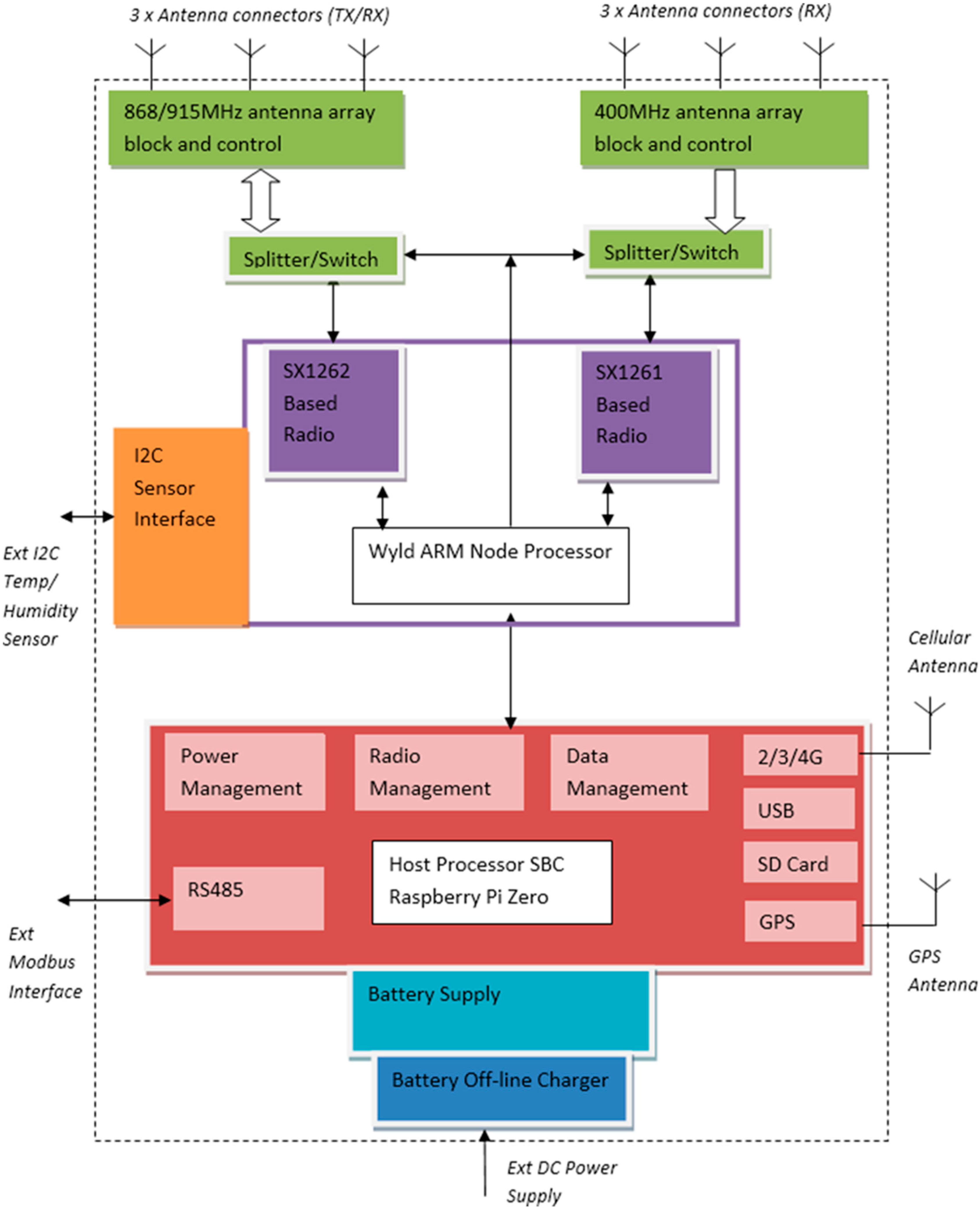
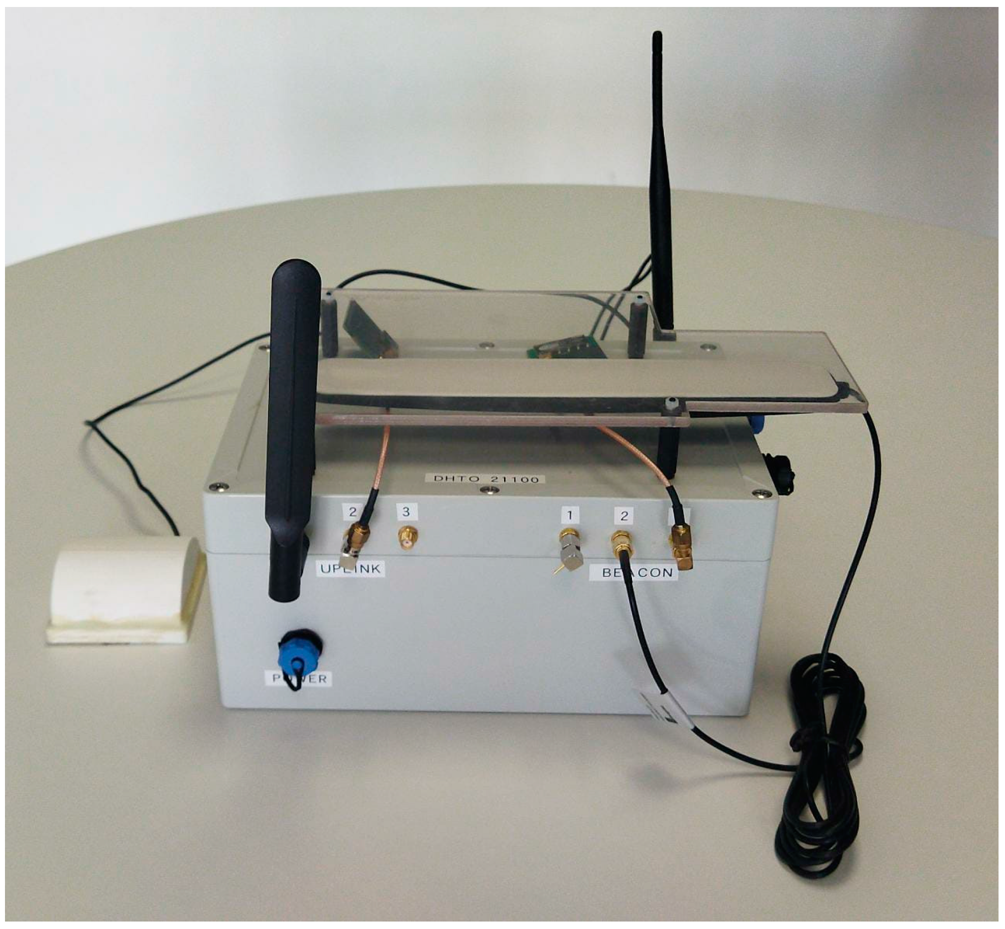
- IoT terminal design: This section describes the design of the IoT terminal. The terminal is responsible for transmitting data to the satellite, as well as communicating with ground-based sensors and other IoT devices.
- Link Budget Analysis: This section lists the requirements for the link budget and calculates the minimum power required for a successful link margin of transmission.
2.1. Orbital Parameters
2.1.1. Semi-Major Axis (a)
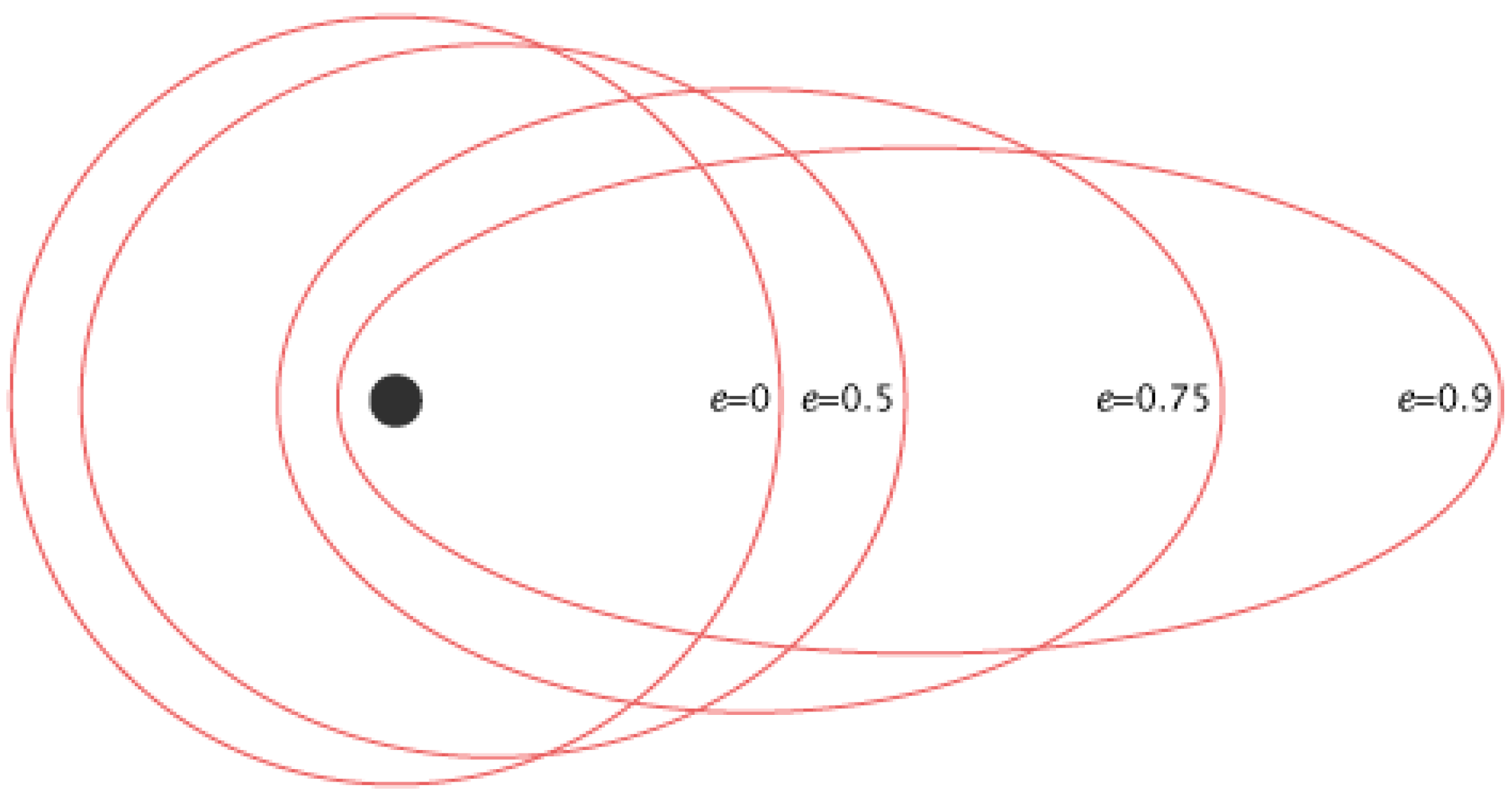
2.1.2. Eccentricity (e)
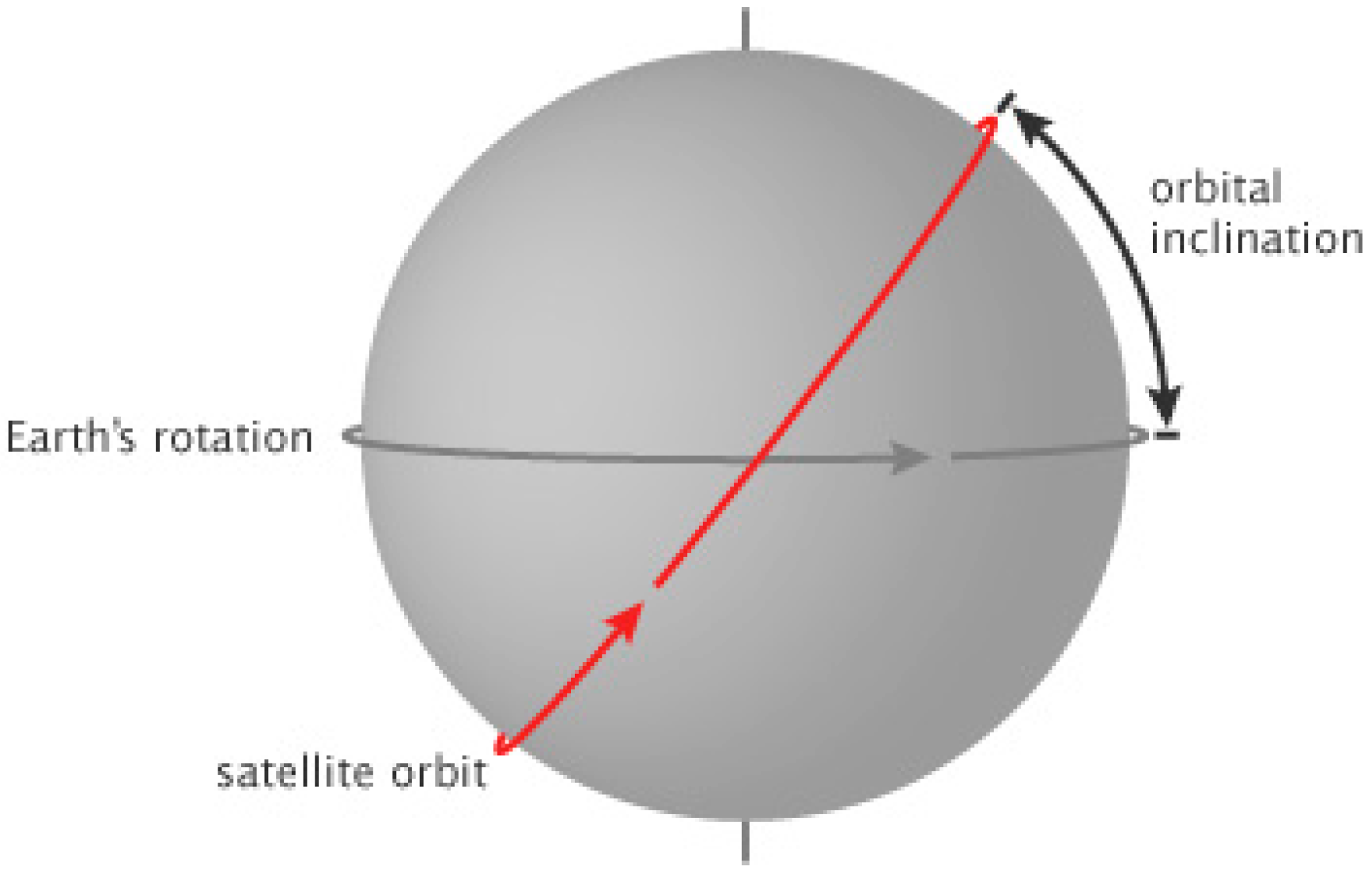
2.1.3. Inclination (i)
2.2. Comparison between SSO and Lower Inclination Orbit
2.3. Lower Inclination Orbit Mission Definition
2.4. LoRa-IoT Design Requirements
- The IoT terminal shall be able to operate autonomously and under remote object control for different use-cases.
- The IoT terminal shall be able to transmit LoRa-CSS packets.
- The IoT terminal shall be able to transmit and receive LoRaWAN packets.
- The IoT terminal shall be able to provide interfaces to sensors.
- The IoT terminal shall be able to provide a transceiver power within the allowed range.
- The IoT terminal shall be able to uplink data to the satellite with the specified frequency range.
- The IoT terminal shall be able to withstand space environment temperatures.
- The IoT terminal shall be able to carry a portable battery that power the terminal for a duration of 7 days.
- The IoT terminal shall be able to carry a memory to store the collected data from sensors.
- The IoT terminal shall be able to carry an antenna and a GPS.
- The IoT terminal shall be able to transmit 50 bytes per LoRa message.
- The LoRa Payload shall be able to fit within the 3U CubeSat platform.
- The LoRa Payload shall be able to withstand the operating temperature of the space environment.
- The LoRa Payload shall be work within the specific frequency range selected by IoT terminal.
- The LoRa Payload shall be able to receive data from the ground terminal.
- The LoRa Payload shall follow the CubeSat Space Protocol (CSP)
- The LoRa Payload shall have high sensitivity Received Signal Strength Indicator (RSSI).
- The LoRa Payload shall consume low power.
- The LoRa Payload shall have a weight up-to 200 g.
2.5. IoT Terminal Design
2.6. Link Budget Analysis
2.6.1. Receiver Sensitivity
2.6.2. Link Margin
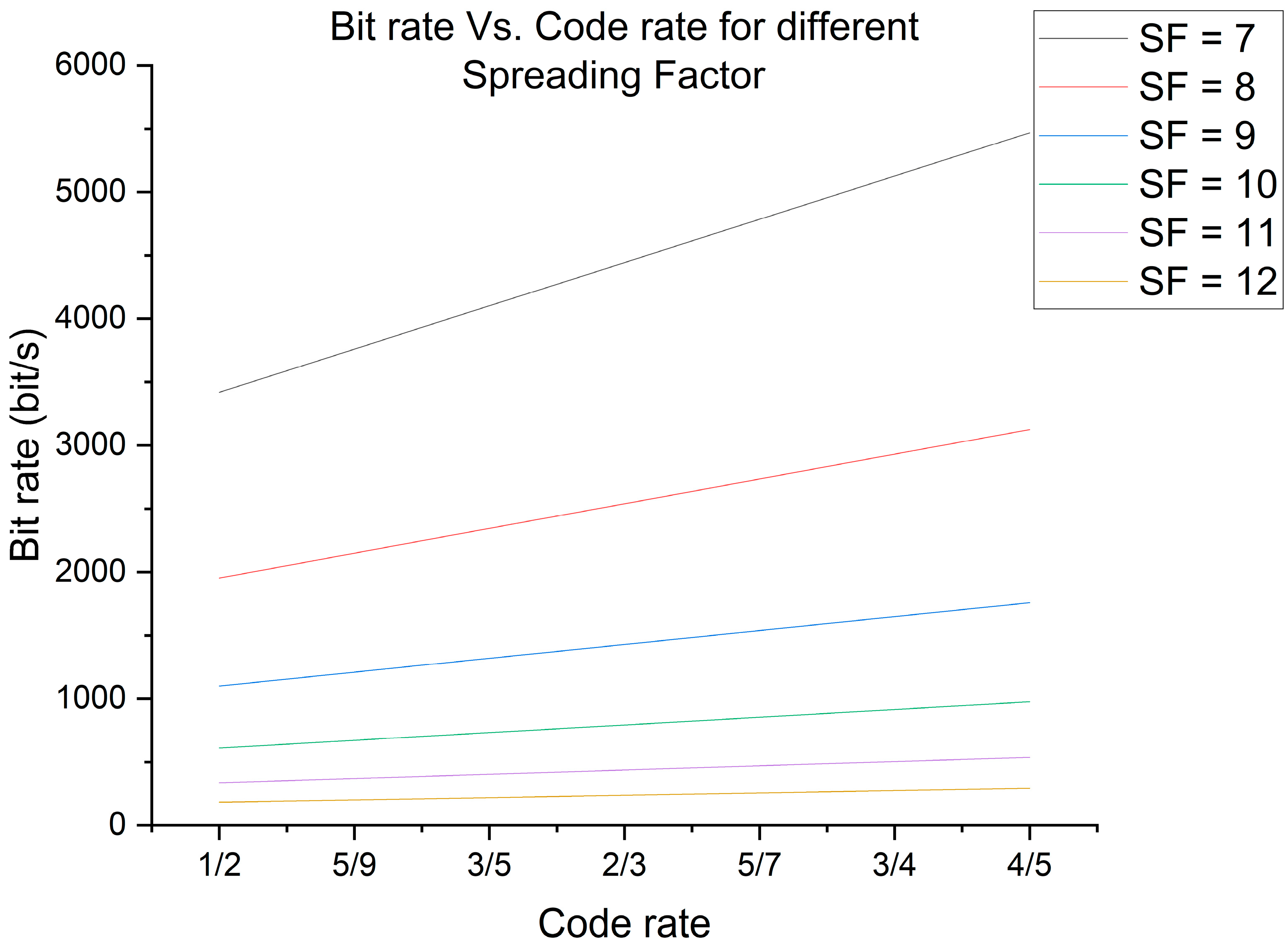
2.6.3. Bit Rate
2.6.4. Airtime
2.6.5. Design Indicators and Criteria
3. Results and Discussion
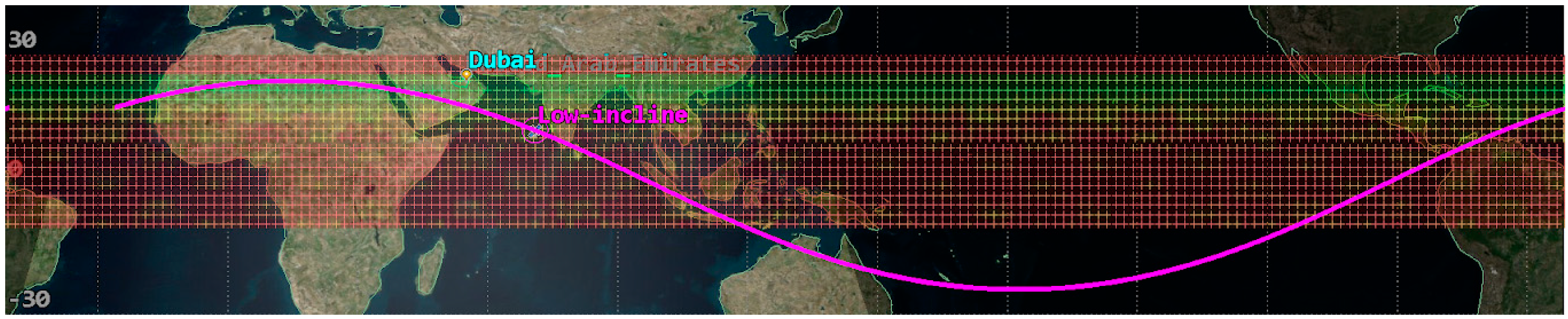
3.1. Ground Track Analysis
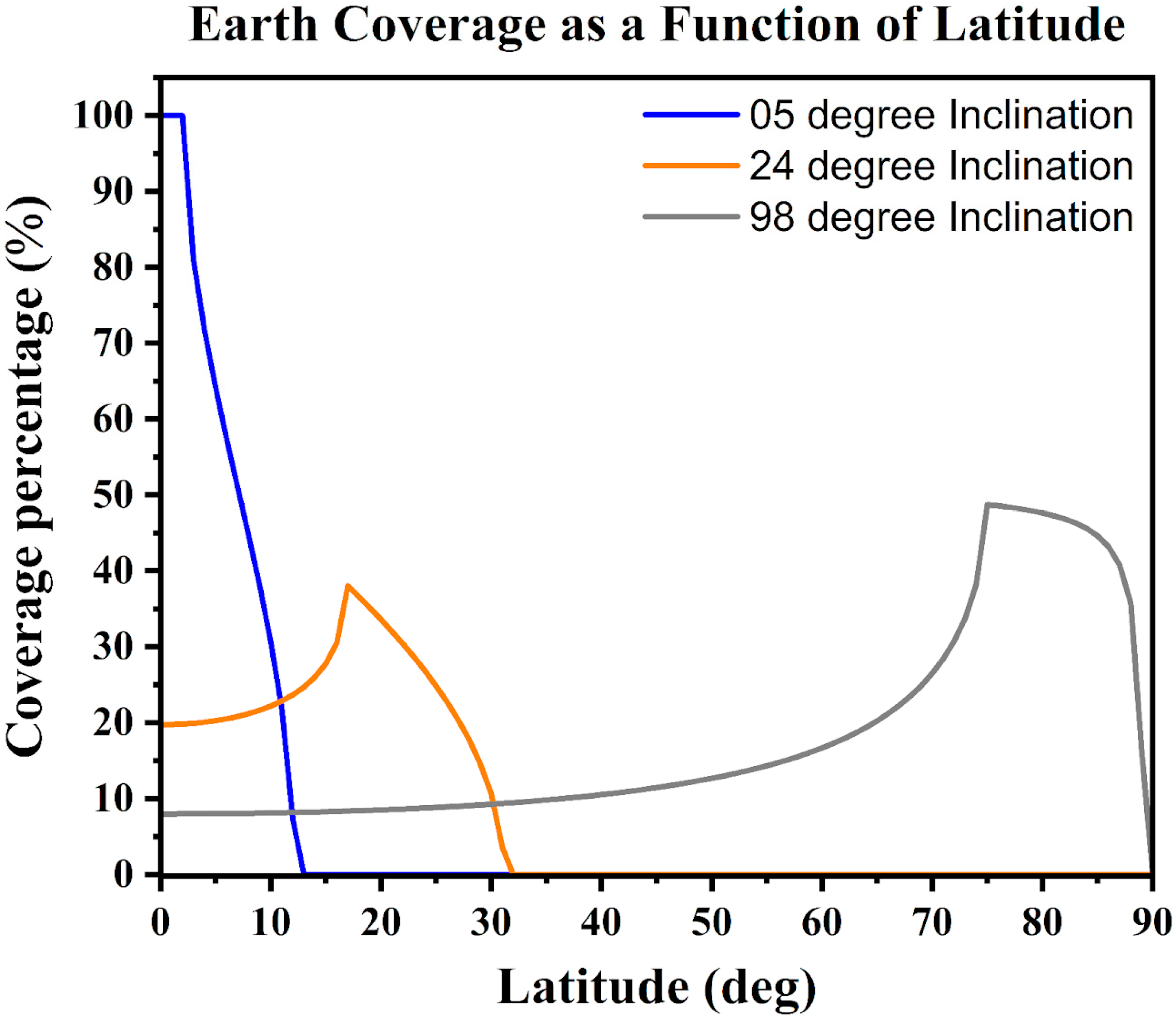
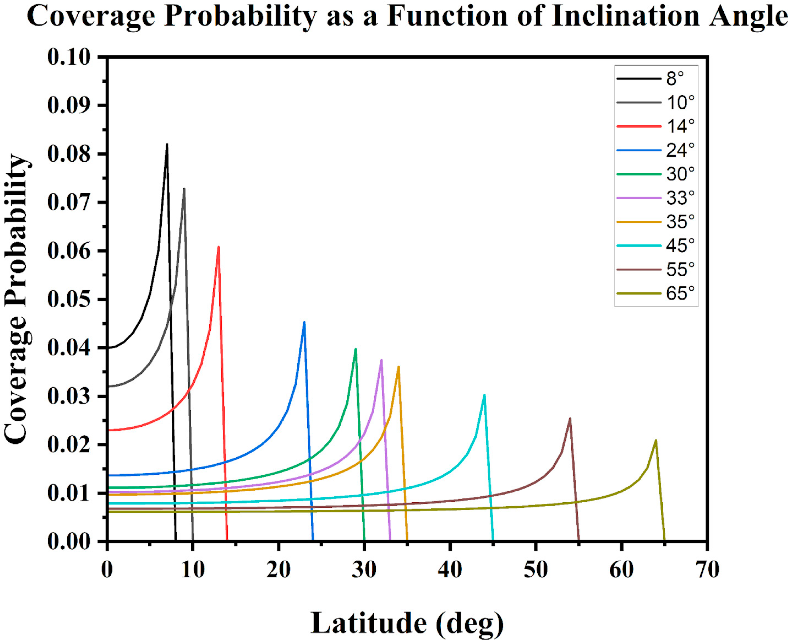
3.2. Coverage Percentage
3.3. Coverage Time
3.4. Accumulated Coverage
3.5. Access Time
3.6. Average Revisit Time
3.7. Link Budget Simulation
3.7.1. Link Budget Sample Calculation
3.7.2. Link Margin
3.7.3. Bit Rate
3.7.4. Airtime
3.8. Weather Real-Time Satellite Data
4. Conclusions
Author Contributions
Funding
Institutional Review Board Statement
Informed Consent Statement
Data Availability Statement
Conflicts of Interest
References
- Kamalaldin, K.; Okasha, M. Low Inclination Circular Orbits for Remote Sensing Satellites. Appl. Mech. Mater. 2014, 629, 298–303. [Google Scholar] [CrossRef]
- Centenaro, M.; Costa, C.E.; Granelli, F.; Sacchi, C.; Vangelista, L. A Survey on Technologies, Standards and Open Challenges in Satellite IoT. IEEE Commun. Surv. Tutor. 2021, 23, 1693–1720. [Google Scholar] [CrossRef]
- Bluetooth® Technology Website—The Official Website for the Bluetooth Wireless Technology. Get up to Date Specifications, News, and Development Info. Available online: https://www.bluetooth.com/ (accessed on 8 December 2022).
- Farahani, S. Chapter 5—RF Propagation, Antennas, and Regulatory Requirements. In ZigBee Wireless Networks and Transceivers; Farahani, S., Ed.; Newnes: Burlington, NJ, USA, 2008; pp. 171–206. ISBN 978-0-7506-8393-7. [Google Scholar]
- Better and Safer Smart Homes Are Built on Z-Wave. Available online: https://www.z-wave.com (accessed on 8 December 2022).
- Bor, M.; Vidler, J.; Roedig, U. LoRa for the Internet of Things. In Proceedings of the EWSN ‘16: Proceedings of the 2016 International Conference on Embedded Wireless Systems and Networks, Graz, Austria, 15–17 February 2016; Volume 6, pp. 361–366. Available online: https://eprints.lancs.ac.uk/id/eprint/77615/1/MadCom2016_LoRa_MAC.pdf (accessed on 17 January 2023).
- Reynders, B.; Pollin, S. Chirp Spread Spectrum as a Modulation Technique for Long Range Communication. In Proceedings of the 2016 Symposium on Communications and Vehicular Technologies (SCVT), Mons, Belgium, 22 November 2016; pp. 1–5. [Google Scholar]
- Motlagh, N.H. Frequency Hopping Spread Spectrum: An Effective Way to Improve Wireless Communication Performance. In Advanced Trends in Wireless Communications; InTech: Rijeka, Croatia, 2011; p. 187. [Google Scholar]
- Spandonidis, C.; Giordamlis, C. Data-Centric Operations in Oil & Gas Industry by the Use of 5G Mobile Networks and Industrial Internet of Things (IIoT). In Proceedings of the ICDT 2018: The Thirteenth International Conference on Digital Telecommunications, Athens, Greece, 22–26 April 2018. [Google Scholar]
- Xu, B.; Li, X.; Ma, Y.; Xin, X.; Kadoch, M. Dual Stream Transmission and Downlink Power Control for Multiple LEO Satellites-Assisted IoT Networks. Sensors 2022, 22, 6050. [Google Scholar] [CrossRef] [PubMed]
- Lin, Z.; Niu, H.; An, K.; Wang, Y.; Zheng, G.; Chatzinotas, S.; Hu, Y. Refracting RIS-Aided Hybrid Satellite-Terrestrial Relay Networks: Joint Beamforming Design and Optimization. IEEE Trans. Aerosp. Electron. Syst. 2022, 58, 3717–3724. [Google Scholar] [CrossRef]
- An, K.; Lin, M.; Ouyang, J.; Zhu, W.-P. Secure Transmission in Cognitive Satellite Terrestrial Networks. IEEE J. Sel. Areas Commun. 2016, 34, 3025–3037. [Google Scholar] [CrossRef]
- Sanad, I. Design of Remote. Sensing Satellite Orbit. Ph.D. Thesis, Military Technical College, Cairo, Egypt, January 2013. [Google Scholar] [CrossRef]
- Zheng, Y.; Lin, B.; Li, R.; Liu, Y. The Design and Maintenance of Low-Orbit Navigation Constellation for Traffic Control in a Smart City. Sensors 2022, 22, 9478. [Google Scholar] [CrossRef] [PubMed]
- Cakaj, S. The Parameters Comparison of the “Starlink” LEO Satellites Constellation for Different Orbital Shells. Front. Commun. Netw. 2021, 2, 643095. [Google Scholar] [CrossRef]
- Types of Orbits. Available online: https://www.esa.int/Enabling_Support/Space_Transportation/Types_of_orbits (accessed on 15 June 2022).
- Abdelkhalik, O.; Gad, A. Optimization of Space Orbits Design for Earth Orbiting Missions. Acta Astronaut. 2011, 68, 1307–1317. [Google Scholar] [CrossRef]
- Gopinath, N.S.; Ravindrababu, T.; Rao, S.V.; Daniel, D.A.; Goel, P.S. Taking Advantage of Inclination Variation in Resonant Remote-Sensing Satellite Orbits. Acta Astronaut. 2004, 55, 453–459. [Google Scholar] [CrossRef]
- Jäggi, A.; Montenbruck, O.; Moon, Y.; Wermuth, M.; König, R.; Michalak, G.; Bock, H.; Bodenmann, D. Inter-Agency Comparison of TanDEM-X Baseline Solutions. Adv. Space Res. 2012, 50, 260–271. [Google Scholar] [CrossRef]
- Nadoushan, M.J.; Assadian, N. Repeat Ground Track Orbit Design with Desired Revisit Time and Optimal Tilt. Aerosp. Sci. Technol. 2015, 40, 200–208. [Google Scholar] [CrossRef]
- Song, Z.; Chen, X.; Luo, X.; Wang, M.; Dai, G. Multi-Objective Optimization of Agile Satellite Orbit Design. Adv. Space Res. 2018, 62, 3053–3064. [Google Scholar] [CrossRef]
- Gavish, B. Low Earth Orbit Satellite Based Communication Systems—Research Opportunities. Eur. J. Oper. Res. 1997, 99, 166–179. [Google Scholar] [CrossRef]
- Cho, M.; Hirokazu, M.; Graziani, F. Introduction to Lean Satellite and ISO Standard for Lean Satellite. In Proceedings of the 2015 7th International Conference on Recent Advances in Space Technologies (RAST), Istanbul, Turkey, 16–19 June 2015; pp. 789–792. [Google Scholar]
- 14:00–17:00 ISO 19683. 2017. Available online: https://www.iso.org/standard/66008.html (accessed on 28 December 2022).
- Masui, H.; Cho, M.; Hatamura, T.; Shimizu, T. Activity and Strategy for Lean Satellite in Kyushu Institute of Technology. In Proceedings of the 2015 7th International Conference on Recent Advances in Space Technologies (RAST), Istanbul, Turkey, 16–19 June 2015; pp. 803–806. [Google Scholar]
- Karunamurthy, J.V.; Bendoukha, S.A.; Nikolakakos, I.; Ghaoud, T.; Ebisi, F.; Alkharrat, M.R. Adaptive Technique for LoRa Communication with LEO Nanosatellite. In Proceedings of the 2021 IEEE Microwave Theory and Techniques in Wireless Communications (MTTW), Riga, Latvia, 7–8 October 2021; pp. 182–187. [Google Scholar]
- Kepler, J. Annex 1. Definition of Orbital Parameters and Important Concepts of Celestial Mechanics. Available online: https://upcommons.upc.edu/bitstream/handle/2099.1/9644/annexa.pdf?sequence=2&isAllowed=y (accessed on 6 December 2022).
- Catalog of Earth Satellite Orbits. Available online: https://earthobservatory.nasa.gov/features/OrbitsCatalog (accessed on 28 December 2022).
- Chapter 3—The Classical Orbital Elements (COEs)—Introduction to Orbital Mechanics. Available online: https://oer.pressbooks.pub/lynnanegeorge/chapter/chapter-3-the-classical-orbital-elements-coes/ (accessed on 4 January 2023).
- Murthy, D.R.; Raju, V.K.; Ramanjappa, T.; Karidhal, R.; Kande, V.M. Small Satellites in Inclined Orbits to Increase Observation Capability Feasibility Analysis. Available online: https://acadpubl.eu/jsi/2018-118-16-17/articles/17/18.pdf (accessed on 23 December 2022).
- Thapa, N.; Krishnakumar, A.K.; Sharma, N.B.; Sarkar, A.; Sarkar, S.S. Simulation Study on Inclined Orbit Constellation of High-Resolution Electrooptical Sensors for Enhanced Imaging Efficiency in Region of Interest. J. Appl. Remote Sens. 2022, 16, 037503. [Google Scholar] [CrossRef]
- Haitaamar, Z.N.; Bendoukha, S.A.; Karunamurthy, J.V. Design and Performance Analysis of LoRa Internet of Things Terminal for Multi-Vendor Satellite Constellation. In Proceedings of the 2022 Workshop on Microwave Theory and Techniques in Wireless Communications (MTTW), Riga, Latvia, 5 October 2022; pp. 165–170. [Google Scholar]
- Ltd, R.P. Buy a Raspberry Pi Zero W. Available online: https://www.raspberrypi.com/products/raspberry-pi-zero-w/ (accessed on 1 July 2022).
- RS-485 Serial Interface Explained. Available online: https://www.cuidevices.com/blog/rs-485-serial-interface-explained (accessed on 1 July 2022).
- SX1261. Available online: https://www.semtech.com/products/wireless-rf/lora-core/sx1261 (accessed on 15 June 2022).
- Neely, M.; Hamerstone, A.; Sanyk, C. Chapter 2—Basic Radio Theory and Introduction to Radio Systems. In Wireless Reconnaissance in Penetration Testing; Neely, M., Hamerstone, A., Sanyk, C., Eds.; Syngress: Boston, MA, USA, 2013; pp. 7–43. ISBN 978-1-59749-731-2. [Google Scholar]
- What Is Omnidirectional Antenna?—Definition from WhatIs.Com. Available online: https://www.techtarget.com/whatis/definition/omnidirectional-antenna (accessed on 15 June 2022).
- Bendoukha, S.A.; Al-Ali, R.; Karunamurthy, J.V.; Ghaoud, T.; Alkharrat, M.R. Link Margin Assessment for CubeSat Using Long Range Communication System. Int. Rev. Aerosp. Eng. 2022, 15, 215. [Google Scholar] [CrossRef]
- Nieto Yll, D. Doppler Shift Compensation Strategies for LEO Satellite Communication Systems. Ph.D. Thesis, Universitat Politècnica de Catalunya Barcelona Tech, Barcelona, Spain, June 2018. [Google Scholar]
- SX1272. Available online: https://www.semtech.com/products/wireless-rf/lora-connect/sx1272 (accessed on 10 March 2023).
- Swain, M.; Zimon, D.; Singh, R.; Hashmi, M.F.; Rashid, M.; Hakak, S. LoRa-LBO: An Experimental Analysis of LoRa Link Budget Optimization in Custom Build IoT Test Bed for Agriculture 4.0. Agronomy 2021, 11, 820. [Google Scholar] [CrossRef]
- Mroue, H.; Nasser, A.; Parrein, B.; Hamrioui, S.; Mona-Cruz, E.; Rouyer, G. Analytical and Simulation study for LoRa Modulation. In Proceeding of the 2018 25th International Conference on Telecommunications (ICT), Saint-Malo, France, 26–28 June 2018. [Google Scholar] [CrossRef]
- Semtech, “LoRa Modulations Basics”, AN 1200.22, May 2015. Available online: https://www.frugalprototype.com/wp-content/uploads/2016/08/an1200.22.pdf (accessed on 18 December 2022).


| Simulation Parameters | SSO Value | Lower Inclined Value |
|---|---|---|
| Semi-major axis | 6928 km | 6928 km |
| Inclination | 98° | 0°–90° |
| Eccentricity | 0° | 0° |
| Variables | |
|---|---|
| Satellite elevation angle | 0 to 90° |
| Spreading Factor | 7 to 12 |
| n in Code Rate | 1 to 4 |
| Limitation and constrains | |
| Ground transceiver power (IoT Terminal) | 25 dBm |
| Nonlicenses central frequency for LoRa | 865.07 MHz |
| Band width | 125 kHz |
| Satellite antenna gain | 6.5 dBi |
| Altitude | 550 km |
| Constants | |
| Boltzmann | −228.6 dBW/Hz/K |
| Receiver noise figure | 458 K |
| Worst case | |
| Ground antenna gain | 0 dBi |
| Losses | (dB) |
| Pointing loss | 0.5 |
| Polarization loss | 0.5 |
| Rain loss | 0.2 |
| Implementation loss | 0.5 |
| Req. Eb/N0 | 6 |
Disclaimer/Publisher’s Note: The statements, opinions and data contained in all publications are solely those of the individual author(s) and contributor(s) and not of MDPI and/or the editor(s). MDPI and/or the editor(s) disclaim responsibility for any injury to people or property resulting from any ideas, methods, instructions or products referred to in the content. |
© 2023 by the authors. Licensee MDPI, Basel, Switzerland. This article is an open access article distributed under the terms and conditions of the Creative Commons Attribution (CC BY) license (https://creativecommons.org/licenses/by/4.0/).
Share and Cite
Haitaamar, Z.; Sulaiman, A.; Bendoukha, S.A.; Rodrigues, D. Lower Inclination Orbit Concept for Direct-Communication-To-Satellite Internet-Of-Things Using Lean Satellite Standard in Near-Equatorial Regions. Appl. Sci. 2023, 13, 5654. https://doi.org/10.3390/app13095654
Haitaamar Z, Sulaiman A, Bendoukha SA, Rodrigues D. Lower Inclination Orbit Concept for Direct-Communication-To-Satellite Internet-Of-Things Using Lean Satellite Standard in Near-Equatorial Regions. Applied Sciences. 2023; 13(9):5654. https://doi.org/10.3390/app13095654
Chicago/Turabian StyleHaitaamar, Zineddine, Abdulrahman Sulaiman, Sidi Ahmed Bendoukha, and Diogo Rodrigues. 2023. "Lower Inclination Orbit Concept for Direct-Communication-To-Satellite Internet-Of-Things Using Lean Satellite Standard in Near-Equatorial Regions" Applied Sciences 13, no. 9: 5654. https://doi.org/10.3390/app13095654
APA StyleHaitaamar, Z., Sulaiman, A., Bendoukha, S. A., & Rodrigues, D. (2023). Lower Inclination Orbit Concept for Direct-Communication-To-Satellite Internet-Of-Things Using Lean Satellite Standard in Near-Equatorial Regions. Applied Sciences, 13(9), 5654. https://doi.org/10.3390/app13095654