Article

Dynamic Characteristics Analysis of a Rod Fastening Rotor System Considering Contact Roughness

1
School of Mathematical Sciences, Daqing Normal University, Daqing 163712, China
2
Institute of Vibration Engineering, Northwestern Polytechnical University, Xi’an 710072, China
3
School of Mechanics and Aerospace Engineering, Southwest Jiaotong University, Chengdu 610031, China
*
Author to whom correspondence should be addressed.
Appl. Sci. 2023, 13(8), 5009; https://doi.org/10.3390/app13085009
Submission received: 7 March 2023 / Revised: 7 April 2023 / Accepted: 11 April 2023 / Published: 17 April 2023
(This article belongs to the Section Mechanical Engineering)

Abstract

:
A rod fastening rotor is the core component of gas turbines, which affects the working stability and service life of the whole machine. The characterization of the contact mechanism of a joint’s interface is a key problem in dynamic prediction. The aim of this paper is to gain insight into the influence of the joint’s interface on the dynamic characteristics of the rod fastening rotor system. According to the equivalent bending stiffness of the joint’s interface, the natural frequency of the system is obtained by the analytical method, where the normal contact stiffness of the joint’s interface related to the frequency index is established on the theory of fractal contact analysis. After that, the effects of key parameters on the contact stiffness are discussed in detail. Finally, the variations in the vibration frequency are further revealed as well.

1. Introduction

Rod fastening rotors have become one of the main structures of gas turbines due to their advantage of convenient maintenance and good performance [1,2,3,4].
The rotor system includes rods, discs, shafts and supports, where the phenomena of contact and friction usually happen in the discs. Therefore, contact stiffness plays an important role in the dynamic characteristics of the rotor system. It is of significance to understand the mechanical characteristics of the rod fastening rotor system in advance.
Up to now, three kinds of methods for describing the contact stiffness of the joint’s interface are widely used, including the equivalent method [5,6], corrected matrix [7,8] and virtual material method [9,10]. The so-called equivalent stiffness method means that the contact behavior is described by the linear spring and viscous damping. Hartwigsen et al. [11,12] obtained the response of the bolted beam through a transient excitation test, from which the mechanical interface parameters are identified. After that, the dynamic equation of the system was further established by assembling the contact element and the whole component in [11,12]. Link et al. [13] used a nonlinear spring to describe the nonlinear characteristic of the interface, where the stiffness of the nonlinear spring was determined by the foundation excitation test. In reference [14], the contact mechanism of the interface is seen as the combination of a hinge and angular spring. According to the finite element method, Qin et al. [15] gave the change law of contact stiffness with different bolt loosening.
As for the corrected stiffness matrix and virtual material, lots of researchers have made great endeavors on them. Hong et al. [7] investigated the mechanism related to non-continuity in the disc joints. By modification of the stiffness of the beam element, Qin et al. [16,17] and Lu et al. [18] discussed several important factors, such as disc contact and normal preload. Su et al. [19] regarded the joint’s interface of the rod fastening rotor as a virtual material with stiffness and obtained the equivalent stiffness through the finite element analysis. Jalali et al. [20] set up a finite element model of a rotor system with disc contact, where the thin-layer element theory was adopted. Beer [21] presented the two- and three-dimensional contact elements.
When analyzing the contact stiffness, the rough interfaces are mainly focused. The most favorable model for this purpose is the Greenwood–Williamson statistical model [22]. According to the boundary element method, Pohrt et al. [23] calculated the contact stiffness of the elastomer with a fractal rough surface. Ciavarella et al. [24] studied the two-dimensional contact of the interface based on the Weierstrass Mandelbrot (W-M) function and obtained the elastic contact stiffness. Majumdar et al. [25,26] established the fractal model for contact interface and W-M fractal function. Meanwhile, the analytical expressions of contact load and contact area under elastic-plastic conditions were determined in references [25,26]. By utilizing the numerical simulation, Goerke et al. [27] studied the mechanical mechanism of the isotropic fractal interface in the elastic-plastic condition. Liu et al. [28] discussed disc contact by using the isotropic fractal interface when both elastic contact and plastic contact are considered. Xu et al. [29] observed the relationship between the grade of the asperity and the contact load and the contact stiffness of the interface. Aiming at a rod-fastened rotor system, Zhuo et al. [30] investigated how surface roughness affects joint stiffness. Jiang et al. [31] carried out research on interface stiffness based on the fractal-curve description of the topology. Elastic-plastic contact and fractal theory was studied by Kogut [32] and Wang [33,34].
The purpose of this study is to investigate the effect of the joint’s interface on the dynamic characteristics of the rod fastening rotor system. Based on the fractal theory, the contact mechanical mechanism of the joint’s interface is analytically characterized, and then the equivalent stiffness model related to the grade of asperity is established. The contact stiffness expressions of all kinds of asperities under elastic, elastic-plastic and plastic states are derived. At last, the equivalent bending stiffness is introduced to the rod fastening rotor system and the dynamic characteristics are discussed. In addition, the influences of the grade of asperity and the fractal parameters on the natural frequency of the system are revealed as well.

2. Dynamics Modeling of Rod Fastening Rotor

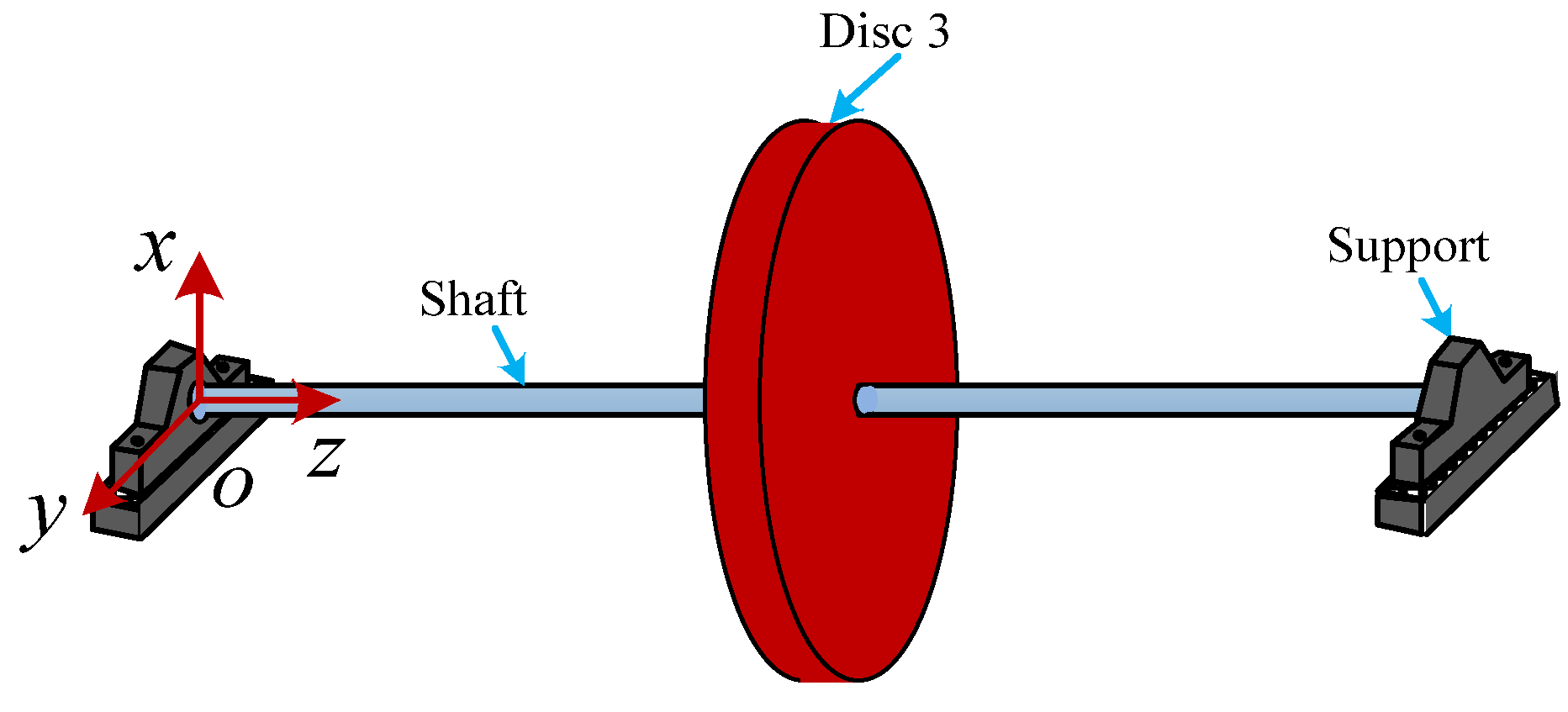
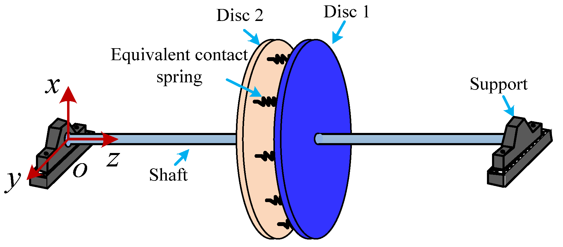
The rotor system considering the disc contact roughness of rods is established in this section. As shown in Figure 1, the global coordinate system is o - x y z . Through several rods, discs 1 and 2 are connected, which are installed in the middle of the flexible shaft. Since the mass of the flexible shaft is much smaller than that of the two discs, it is ignored in the modeling process of the system. Meanwhile, the boundary conditions of the flexible shaft are the fixed supports.
Assuming that the effects reduced by the contact roughness of the joint’s interface are temporarily put aside, the two discs are integrated into a whole. Under this circumstance, the rod fastening rotor system shown in Figure 1 can be seen as a classical Jeffcott rotor system, as shown in Figure 2.
When disc 3 is installed in the middle of the shaft, the bending stiffness of the left and right parts of the massless shaft can be obtained according to the compliance coefficient method, namely
k 1 = k 2 = 48 E r s I L 3
where E r s denotes the elastic modulus of the massless shaft, I denotes the second moment of area of the cross-section of the shaft and L denotes the length of the shaft. It is noted that the rotor system is subjected to centrifugal action, and the whirling motion happens synchronously. If the integrated disc is installed in the middle of the shaft, the normal of the disc is parallel to axis o z . This means that the gyroscopic effect of the disc does not exist in the rotor system.
According to Newton’s second law, the governing equation of motion of the dynamic model in the coordinate plane of x o z can be obtained as follows:
( m 1 + m 2 ) x ¨ + ( k 1 + k 2 ) x = ( m 1 + m 2 ) e ω 2 cos ω t
where m 1 and m 2 denote the mass of discs 1 and 2, respectively. e denotes the eccentricity of the integrated disc, and ω denotes the rotational speed of the system.
The above expression suggests that according to the theory of linear vibration, when discs 1 and 2 are rigidly connected, the natural frequency of the Jeffcott rotor system (see Figure 2) is mainly determined by the integrated disc mass and the bending stiffness of the massless flexible shaft.
For the rod fastening rotor system, the contact roughness of the joint’s interface is a crucial factor that directly affects the dynamic characteristics of the system. Therefore, a schematic diagram of an equivalent rotor system is depicted in Figure 3, in which the equivalent contact spring is used to describe the contact mechanism of the joint’s interface. Therefore, the governing equation of motion of the equivalent rotor system in the coordinate plane of x o z can be expressed as
( m 1 0 0 m 2 ) ( x ¨ 1 x ¨ 2 ) + ( k 1 + k 2 k 3 k 3 k 2 + k 3 ) ( x 1 x 2 ) = ( m 1 e 1 ω 2 cos ω t m 2 e 2 ω 2 cos ω t )
where k 3 denotes the equivalent bending stiffness of the joint’s interface. e 1 and e 2 denotes the eccentricities of discs 1 and 2.
This illustrates that the first and second natural frequencies of the rotor system are closely related to the mass of the two discs, the bending stiffness of the massless flexible shaft and also the bending stiffness of the equivalent contact spring. Therefore, in order to predict the dynamic characteristics of the rod fastening rotor system more accurately, the contact mechanism of the joint’s interface should be investigated in advance.

3. Characterization of Contact Stiffness of Joint’s Interface

For the rod fastening rotor system, the two discs are connected together by the bolts. The contact between rough surfaces can be seen as an equivalent fractal rough surface in contact with a rigid flat surface. During the modeling process, some assumptions are made as follows:
(1)
The isotropic fractal characteristics of each grade asperity are considered.
(2)
The interaction between each level of asperity is ignored.
(3)
The material hardening phenomenon induced by contact deformation is not taken into consideration.
(4)
The contact behavior in the normal direction is only taken account.

3.1. Contact of Joint’s Interface

In this paper, the W-M function is adopted to describe the two-dimensional rough joint’s interface. According to reference [25], the specific expression is given by
Z ( x ) = G D 1 n = n min cos ( 2 π γ n x ) γ ( 2 D ) n ,   ( 1 < D < 2 )
where Z ( x ) denotes the height of the surface profile, D denotes the fractal dimension of a surface profile, G denotes the length scale of a surface, n min corresponds to the low cut-off frequency of the profile, γ n denotes the frequency spectrum of the surface roughness and n denotes the frequency index of the surface profile, which represents the level of each asperity.
According to Figure 4, for the nth level asperity surface, the surface profile curve can be obtained according to Equation (4), namely
Z n ( x ) = G D 1 l 2 D cos ( π x l )
where l denotes the length scale of the asperity, which obeys l = 1 / γ n .
As shown in Figure 4, the contact between a single asperity and a rigid plane happens. According to Equation (5), for the two-dimensional rough surface, the radius of the asperity can be written as
R n = | ( 1 + ( d z d x ) 2 ) 3 2 ( d 2 z d x 2 ) | x = 0 = 1 π 2 G D 1 γ n D
The height of the n-th level asperity can be derived as
δ n = Z n ( 0 ) = G D 1 γ n ( 2 D )
As introduced in the theory of contact mechanics, there are three steps in the process of contact between the rigid plane and the n-th level asperity surface, including the elastic part, elastic-plastic part and plastic part, respectively.
According to reference [35], combined with the above different steps, the relations between the deformation of single asperity and the contact area can be derived, respectively, as
{ a n e = π R n w n ( w n w n e c ) a n e p 1 = a n e c 0.93 ( w n w n e c ) 1.136 ( w n e c < w n 6 w n e c ) a n e p 2 = a n e c 0.94 ( w n w n e c ) 1.146 ( 6 w n e c < w n 110 w n e c ) a n p = 2 π R n w n ( 110 w n e c < w n )
Correspondingly, the contact force of the single asperity at the different stages can be expressed as
{ F n e = 2 3 E π 1 R n 0.5 a n e 1.5 ( w n w n e c ) F n e p 1 = 2 3 ψ H × 1.1282 a n e c 0.2544 a n e p 1 1.2544 ( w n e c < w n 6 w n e c ) F n e p 2 = 2 3 ψ H × 1.4988 a n e c 0.1021 a n e p 2 1.1021 ( 6 w n e c < w n 110 w n e c ) F n p = H a n p ( 110 w n e c < w n )
where the subscripts ne, nep1, nep2 and np represent the elastic stage, the first elastic-plastic stage, the second elastic-plastic stage and the plastic stage, respectively. The subscript nec represents the critical elastic deformation of the asperity. H denotes the material hardness.
According to reference [35], critical elastic deformation can be expressed as
w n e c = ( π ψ H 2 E ) 2 R n
where the hardness coefficient ψ and the equivalent elastic modulus E , respectively, obey
ψ = 0 . 454 + 0 . 41 ν 2
E = 1 1 ν 1 2 E 1 1 ν 2 2 E 2
where E 1 and E 2 denote the elastic modulus of hard and soft materials, and ν 1 and ν 2 denote the Poisson’s ratio of hard and soft materials, respectively.
According to Equation (10), the critical contact area and the critical contact load at the elastic stage can be expressed as
a n e c = π 3 ( ψ H 2 E ) 2 R n 2
F n e c = ψ 3 H 3 π 3 R n 2 6 E 2
When condition δ n w n e c is satisfied, it can be further derived by means of simultaneous Equations (6), (7) and (10) so that
G D 1 γ n ( 2 D ) ( π ψ H 2 E ) 2 1 G D 1 γ n D
Therefore, the critical elastic profile index can be expressed as
n e c = int { ln [ ( π ψ H 2 E ) 2 ( 1 G ) 2 D 2 ] ( 2 D 2 ) ln γ }
where int { } is rounded to the right. Therefore, the asperities at this grade only have elastic deformation.
By a similar method, the critical elastic-plastic index and the plastic index can be, respectively, written as.
n e p c = int { ln [ 6 ( π ψ H 2 E ) 2 ( 1 G ) 2 D 2 ] ( 2 D 2 ) ln γ }
and
n p c = int { ln [ 110 ( π ψ H 2 E ) 2 ( 1 G ) 2 D 2 ] ( 2 D 2 ) ln γ }
That is to say the deformation state of asperity can be determined by the asperity grade instead of the actual deformation.

3.2. Size Distribution Function

According to reference [26], the area distribution function can be given by
n ( a ) = | d N d a | = D 2 · a l D / 2 a 1 + D / 2
where a l denotes the maximum contact area of asperities.
Then the real contact area of the entire rough surface can be further derived as
A r = 0 a l n ( a ) a d a = D 2 D a l
On the other hand, due to the multi-scale of the rough surface, the contact area function of asperity depends on the value of the scale number. Therefore, the real contact area can also be expressed as
A r = n = n min n max 0 a n l n n ( a ) a d a = κ D 2 D n = n min n max a n l
Through simultaneous Equations (20) and (21), the expression of coefficient κ is
κ = a l n = n min n max a n l ,   a l = max { a n l }

3.3. Contact Load and Normal Contact Stiffness

When the equivalent fractal rough surface is in contact with a rigid flat surface, the asperities with different grades are under different states. Therefore, the contact load of the joint’s interface is the sum of the contact load of all grades of asperities, namely
F r = F r e + F r e p 1 + F r e p 2 + F r p
where F r e , F r e p 1 , F r e p 2 and F r p denote the contact load, which correspond to elastic deformation, first elastoplastic deformation, second elastoplastic deformation and plastic deformation, respectively. They are further expressed as
F r e = n = n min n e c 0 a n l   κ F n e n ( a ) d a + n = n e c + 1 n max 0 a n e c   κ F n e n ( a ) d a
F r e p 1 = n = n e c + 1 n e p c a n e c a n l κ F n e p 1 n ( a ) d a + n = n e p c + 1 n max a n e c a n e p c κ F n e p 1 n ( a ) d a
F r e p 2 = n = n e p c + 1 n p c a n e p c a n l κ F n e p 2 n ( a ) d a + n = n p c + 1 n max a n e p c a n p c κ F n e p 2 n ( a ) d a
F r p = n = n p c + 1 n max a n p c a n l κ F n p n ( a ) d a
where a n e p c and a n p c represent the critical elastoplastic contact area and the critical plastic contact area of the asperity, respectively. According to Equation (8), the expressions of a n e p c and a n p c are
{ a n e p c = 7.1197 a n e c a n p c = 205.3827 a n e c
The normal contact stiffness of a single asperity can be obtained from Equation (8), so that
{ k n e = d F n e d w n k n e p 1 = d F n e p 1 d w n k n e p 2 = d F n e p 2 d w n k n p = d F n p d w n
On this basis, the normal contact stiffness of all grades of asperities can be further derived as
{ K r e = n = n min n e c 0 a n l κ k n e n ( a ) d a + n = n e c + 1 n max 0 a n e c κ k n e n ( a ) d a K r e p 1 = n = n e c + 1 n e p c 0 a n l κ k n e p 1 n ( a ) d a + n = n e p c + 1 n max a n e c a n e p c κ k n e p 1 n ( a ) d a K r e p 2 = n = n e p c + 1 n p c a n e p c a n l κ k n e p 2 n ( a ) d a + n = n p c + 1 n max a n e p c a n p c κ k n e p 2 n ( a ) d a K r p = n = n p c + 1 n max a n p c a n l κ k n p n ( a ) d a

4. Results and Discussion

4.1. Normal Contact Stiffness of Joint’s Interface

The relationship between normal contact stiffness and contact load for the rough surface is conducted in this part. The main parameters of the rough surface are listed in Table 1.
The contact stiffness of the joint’s interface is the sum of the normal contact stiffness of all grades of asperities, namely
K r = K r e + K r e p 1 + K r e p 2 + K r p
Meanwhile, the nominal contact area of the joint’s interface is defined as
A a = l r 2 = ( l / γ n ) 2
Correspondingly, the dimensionless contact load and the dimensionless normal contact stiffness can, respectively, be expressed as
F r = F r E A a
and
K r = K r E A a
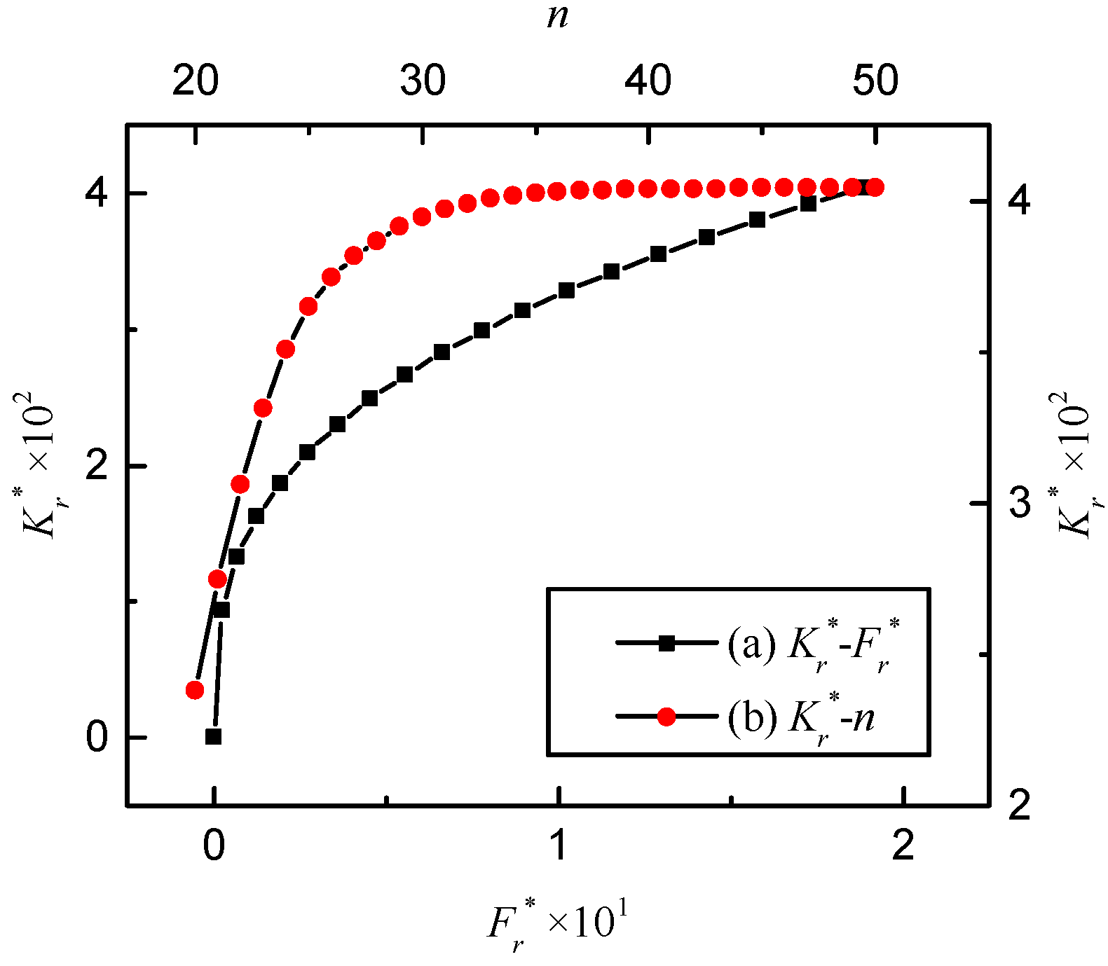
According to Table 1, the elastic, first elastoplastic and second elastoplastic critical frequency indexes can be calculated as n e c = 28 , n e p c = 34 and n p c = 45 , respectively. Then the variation of dimensionless normal contact stiffness is depicted in Figure 5. It is clear that with the increase in the dimensionless contact load, the dimensionless normal contact stiffness rises rapidly at first and then tends to stabilize. This change is consistent with the test results in reference [28]. Because n min is smaller than n e c , the contact stiffness of the joint’s interface is mainly determined by the asperity, which corresponds to the frequency index of this range. As a result, the relation between the dimensionless normal contact stiffness and the contact load is approximately linear.
In addition, the effect of the frequency index on the dimensionless normal contact stiffness is also depicted in Figure 5. As the frequency index mounts up, the dimensionless normal contact stiffness becomes larger.
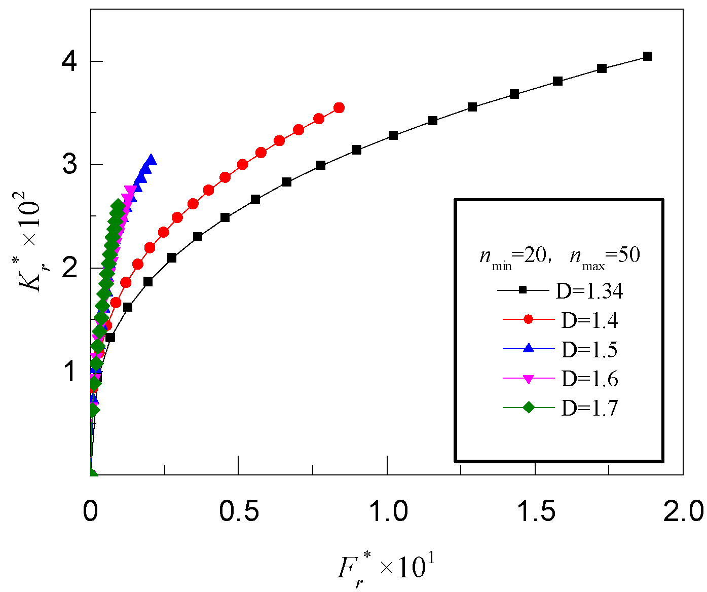
When the characteristic length scale is G = 7 . 342 × 10 11   m and the fractal dimension changes from D = 1 . 34 to D = 1 . 7 , the influences of the fractal dimension on the dimensionless normal contact stiffness change, as shown in Figure 6. With the increase in the fractal dimension D , the dimensionless normal contact stiffness K r * increases synchronously. The main reason for this phenomenon is that the large fractal dimension can lead to the obvious refinement of the surface concave-convex and raise the distribution of the asperity.
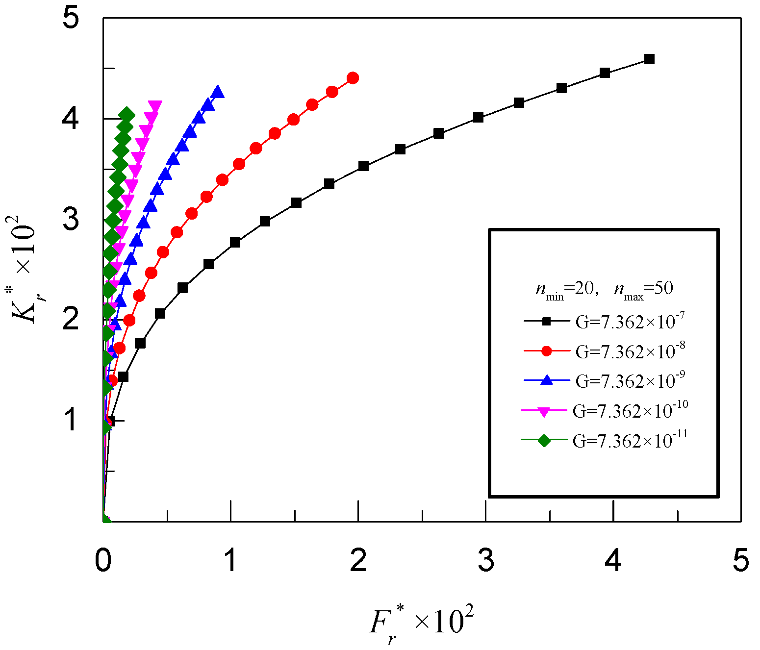
Figure 7 shows the influence of the characteristic length scale G on the dimensionless normal contact stiffness. When the fractal dimension is D = 1 . 34 and the level range of the asperity is n = [ 20 ,   50 ] , the dimensionless normal contact stiffness decreases with an increase in the characteristic length scale. This is because the larger the characteristic length scale G , the rougher the contact surface becomes.

4.2. Dynamic Characteristics of Rod Fastening Rotor System

In this section, the dynamic characteristics of the rod fastening rotor system are revealed. According to reference [36], the main structure parameters of the system are given in Table 2. When the two discs are connected by the bolt preload, the dynamic characteristics of the rod fastening rotor system are mainly determined by the disc mass, shaft bending stiffness and the equivalent bending stiffness of the joint’s interface.
Based on the above analysis of the contact mechanism of the joint’s interface and reference [34], the bending stiffness of the interface can be expressed as
K G = k I a η r a
where I a denotes the actual second moment of area, η r a denotes the ratio of real contact area to the nominal contact area and k denotes the elastic constraint of the equivalent distributed spring shown in Figure 3, which obeys the following form:
k = K r A a
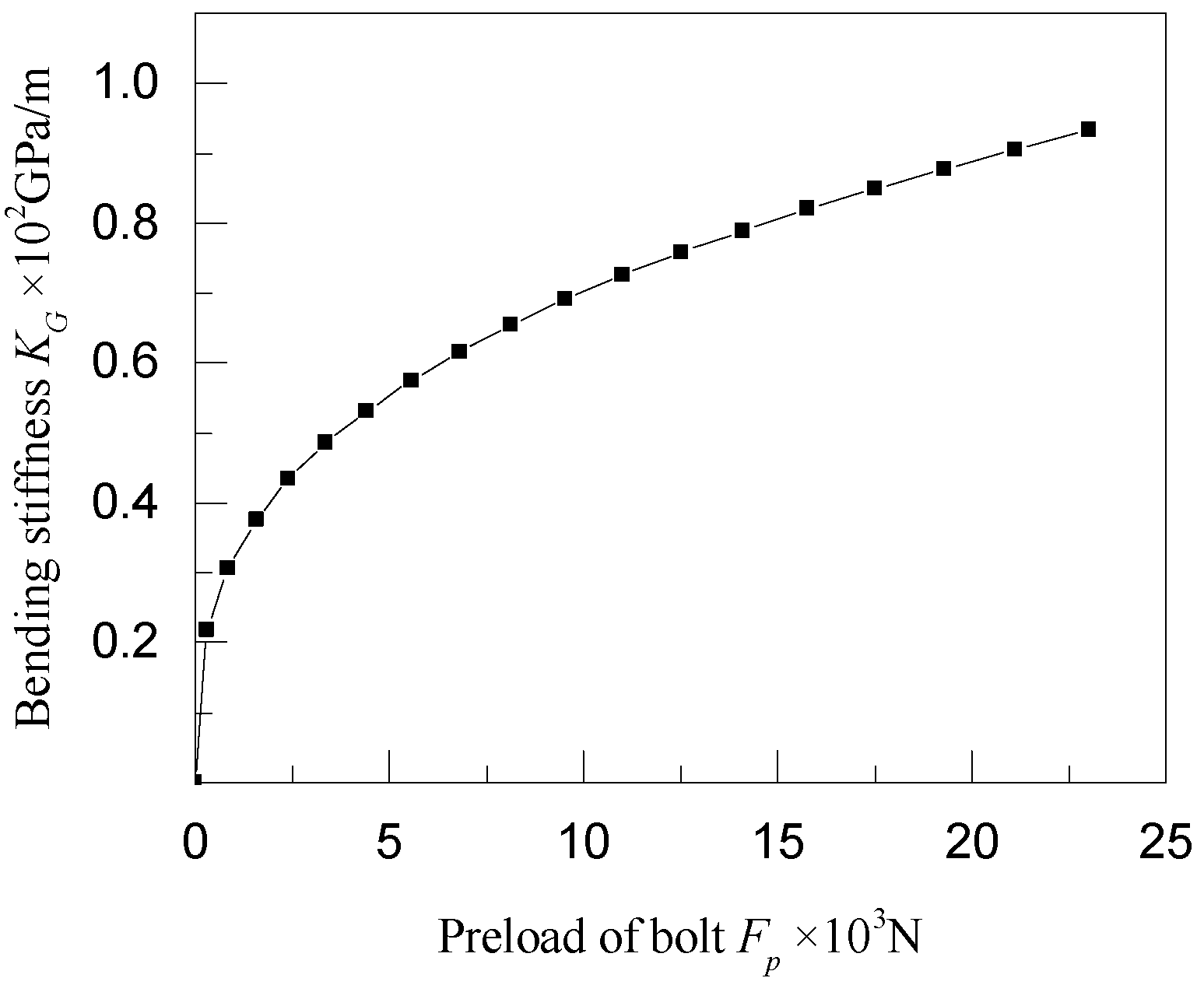
According to reference [36], for No. 45 steel, the elastic modulus of the joint’s interface is 115 . 4   GPa , the surface hardness is 2 . 058   GPa , the fractal dimension D is 1 . 34 and the characteristic length scale G is 7 . 075 × 10 11   m . Thus, the relation between the bending stiffness of the interface and the preload of the bolt is shown in Figure 8. It is clear that due to the increase in the preload of the bolt, the bending stiffness of the interface gradually increases.
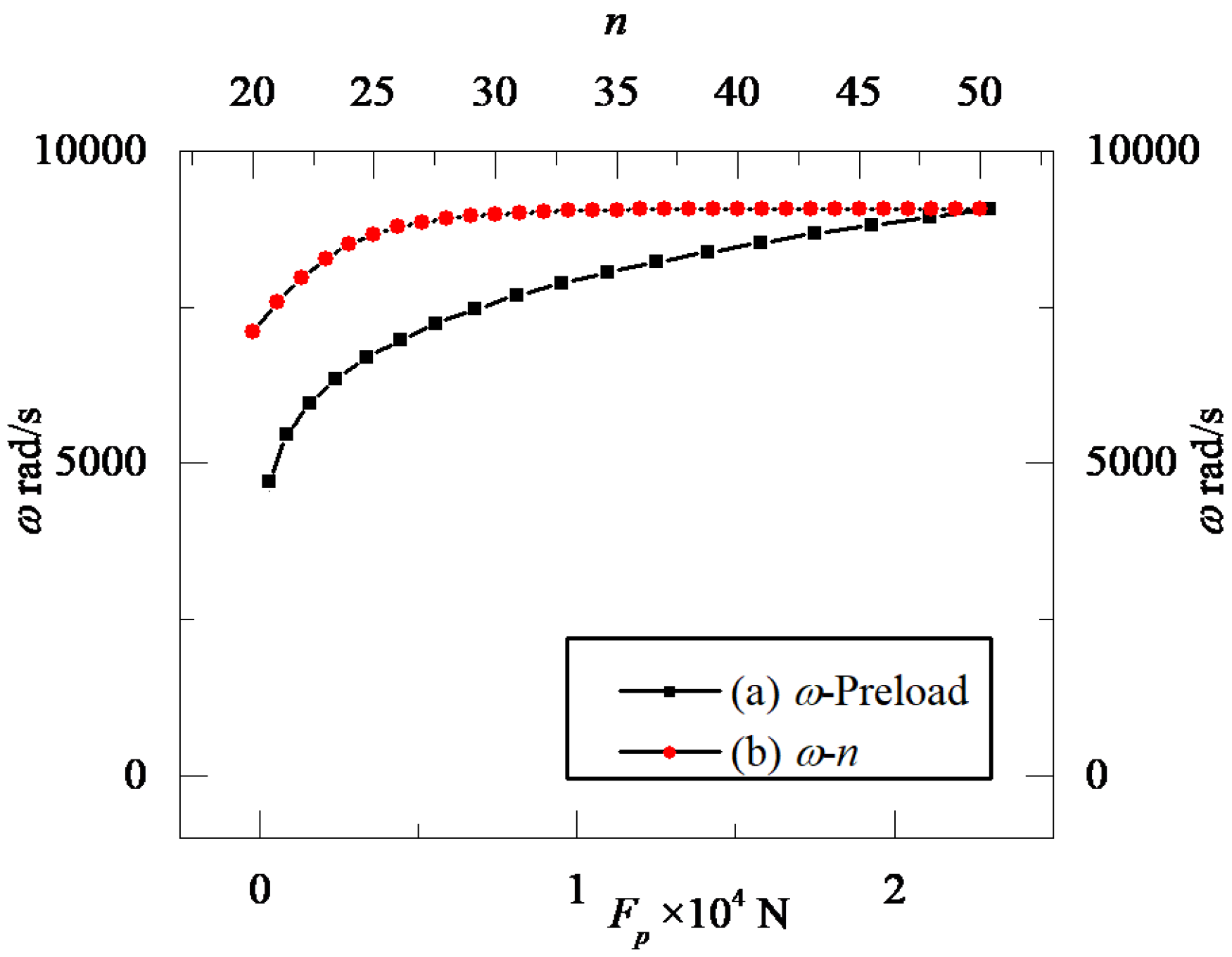
Figure 9 suggests that the preload of the bolt has an assignable influence on the natural frequency of the rod fastening rotor system. The natural frequency of the system increases with the change in preload. This trend of natural frequency is similar to that of the bending stiffness shown in Figure 8. Meanwhile, the inner relationship between the natural frequency and the grade of asperity can be observed in Figure 9 as well.
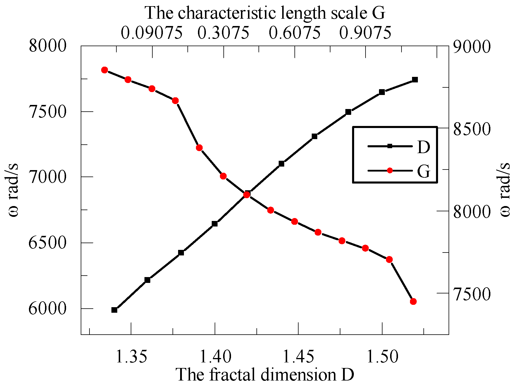
At last, the key parameters (i.e., fractal dimension D and characteristic length scale G ) are taken into consideration. Since the disc contact stiffness appears sensitive to normal contact stiffness and the joint’s interface is sensitive to the fractal dimension and the characteristic length scale, the change in the natural frequency is further discussed in detail. From Figure 10, it is clear that the vibration frequency of the rotor system becomes large with the increase in the fractal dimension. However, it will decrease with an increase in the characteristic length scale. The main reason for this is that the total stiffness of the system is closely related to the bending stiffness of the shaft and the equivalent bending stiffness of the interface. Overall, the trend of the two curves shown in Figure 10 is approximately linear. The physical characteristics of the rod fastening rotor system are mainly determined by the material of the shafts, discs and fastener bolts and the surface finish of the discs.

5. Conclusions

For the rod fastening rotor system adopted in gas turbines, the influences of the joint’s interface on the dynamic characteristics are investigated in this paper. Based on the fractal theory, the contact mechanism of the joint’s interface is characterized by the analytical method and numerical simulation. According to the different deformation conditions of different asperities, the normal contact stiffness of the joint’s interface includes three parts, namely elastic, elastic-plastic and plastic. After that, the influences of the joint parameters, such as fractal dimension, characteristic length scale and grade of asperities, on the contact stiffness of the joint’s interface and the dynamic characteristics of the rod fastening rotor system are discussed in detail. Some conclusions are summarized as follows:
(1)
For the rod fastening rotor system, its dynamic characteristics are different from that of a traditional integral rotor system due to the contact effects of the joint’s interface.
(2)
The contact stiffness of the joint’s interface is closely related to the grade of asperities and the fractal parameters. The contact stiffness increases with an increase in the fractal dimension and a decrease in the characteristic length scale, respectively.
(3)
For the rod fastening rotor, the roughness of the joint’s interface can directly affect the dynamic characteristics and natural frequency of the system. Because the fractal parameters of the joint’s interface are mainly determined by the contact roughness, the natural frequencies of the system are changed accordingly.
(4)
During the dynamic analysis of the rod fastening rotor system, both the structural stiffness of the flexible shaft and the contact stiffness of the joint’s interface should be taken into consideration.

Author Contributions

Methodology, W.Z. and Y.Y.; writing—original draft preparation, W.Z., K.L., Y.G. and Y.Y.; review and editing, K.L., Y.G. and X.R.; supervision, X.R. and Y.G. All authors have read and agreed to the published version of the manuscript.

Funding

This research was funded by the Natural Science Foundation of HeiLongJiang Province, Project No. LH2020A017.

Institutional Review Board Statement

Not applicable.

Informed Consent Statement

Not applicable.

Data Availability Statement

Not applicable.

Conflicts of Interest

The authors declare no conflict of interest.

Nomenclature

k 1 , k 2 Bending stiffness of the shaft
m 1 , m 2 Mass of discs 1 and 2
E r s Elastic modulus of the shaft
L Length of shaft
Z Height of the surface profile
D Fractal dimension of surface profile
G Length scale of a surface
γ n Frequency spectrum of surface roughness
n Frequency index of surface profile
l Length scale of asperity
R n Radius of asperity
w n Deformation of single asperity
H Material hardness
w n e c Critical elastic deformation
ψ Hardness coefficient
E 1 , E 2 Elastic modulus of hard and soft materials
ν 1 , ν 2 Poisson’s ratio of hard and soft materials
a n e c Critical contact area at the elastic stage
F n e c Critical contact load at the elastic stage
a l Maximum contact area of asperities
A r Real contact area of joint’s interface
F r Contact load of the joint’s interface
F r e Contact load of elastic deformation
F r e p 1 Contact load of elastoplastic deformation
F r e p 2 Contact load of elastoplastic deformation
F r p Contact load of plastic deformation
a n e p c Critical elastoplastic contact area
a n p c Critical plastic contact area
K r Normal contact stiffness
K r e Contact stiffness of elastic deformation
K r e p 1 Contact stiffness of elastoplastic deformation
K r e p 2 Contact stiffness of elastoplastic deformation
K r p Contact stiffness of plastic deformation
F r * Dimensionless contact load
K r * Dimensionless contact stiffness
K G Bending stiffness of interface
I a Actual second moment of area

References

  1. Peng, H.; Liu, Z.S.; Wang, G.L.; Zhang, M. Rotor dynamic analysis of tie-bolt fastened rotor based on elastic-plastic contact. In Proceedings of the ASME 2011 Turbo Expo: Technical Conference and Exposition, Vancouver, BC, Canada, 1 January 2011. [Google Scholar]
  2. Liu, S.G.; Ma, Y.H.; Zhang, D.Y.; Hong, J. Studies on dynamic characteristics of the joint in the aero-engine rotor system. Mech. Syst. Signal Process. 2012, 29, 120–136. [Google Scholar]
  3. Mayer, M.H.; Gaul, L. Segment-to-segment contact elements for modeling joint interfaces in finite element analysis. Mech. Syst. Signal Process. 2007, 21, 724–734. [Google Scholar] [CrossRef]
  4. Liu, H. Nonlinear dynamic analysis of a flexible rod fastening rotor bearing system. J. Eng. Mech. 2010, 46, 53. [Google Scholar] [CrossRef]
  5. Luan, Y.; Guan, Z.Q.; Cheng, G.D.; Liu, S. A simplified nonlinear dynamic model for the analysis of pipe structures with bolted flange joints. J. Sound Vib. 2012, 331, 3225–3344. [Google Scholar] [CrossRef]
  6. Meng, C.; Su, M.; Wang, S. An investigation on dynamic characteristics of a gas turbine rotor using an improved transfer matrix method. J. Eng. Gas Turb. Power 2013, 135, 122505-1–122505-12. [Google Scholar] [CrossRef]
  7. Hong, J.; Chen, X.Q.; Wang, Y.F.; Ma, Y.H. Optimization of dynamics of non-continuous rotor based on model of rotor stiffness. Mech. Syst. Signal Process. 2019, 131, 166–182. [Google Scholar] [CrossRef]
  8. Caddemi, S.; Calio, I.; Cannizzaro, F. Closed-form solutions for stepped Timoshenko beams with internal singularities and along-axis external supports. Arch. Appl. Mech. 2013, 83, 559–577. [Google Scholar] [CrossRef]
  9. Mackerle, J. Finite element analysis of fastening and joining: A bibliography. Int. J. Press. Vessel. Pip. 2003, 80, 253–271. [Google Scholar] [CrossRef]
  10. Ahmadian, H.; Mottershead, J.E.; James, S.; Friswell, M.I.; Reece, C.A. Modelling and updating of large surface-to-surface joints in the AWE-MACE structure. Mech. Syst. Signal Process. 2006, 20, 868–880. [Google Scholar] [CrossRef]
  11. Hartwigsen, C.J.; Song, Y.; Mcfarland, D.M.; Bergman, L.A.; Vakakis, A.F. Experimental study of non-linear effects in a typical shear lap joint configuration. J. Sound Vib. 2004, 277, 327–351. [Google Scholar] [CrossRef]
  12. Song, Y.; Hartwigsen, C.J.; Mcfarland, D.M.; Vakakis, A.F.; Bergman, L.A. Simulation of dynamics of beam structures with bolted joints using adjusted Iwan beam elements. J. Sound Vib. 2004, 273, 249–276. [Google Scholar] [CrossRef]
  13. Link, M.; Boeswald, M.; Laborde, S.; Weiland, M.; Calvi, A. An approach to non-linear experimental modal analysis. Nonlinear Model Appl. 2011, 2, 119–128. [Google Scholar]
  14. Gao, J.; Yuan, Q.; Li, P.; Feng, Z.P.; Zhang, H.T.; Lv, Z.Q. Effects of bending moments and pretightening forces on the flexural stiffness of contact interfaces in rod-fastened rotors. J. Eng. Gas Turbines Power 2012, 134, 1492–1494. [Google Scholar] [CrossRef]
  15. Qin, Z.Y.; Han, Q.K.; Chu, F.L. Analytical model of bolted disk-drum joints and its application to dynamic analysis of jointed rotor. Proc. Inst. Mech. Eng. Part C J. Mech. Eng. Sci. 2014, 228, 646–663. [Google Scholar] [CrossRef]
  16. Qin, Z.Y.; Han, Q.K.; Chu, F.L. Bolt loosening at rotating joint interface and its influence on rotor dynamics. Eng. Fail Anal. 2016, 59, 456–466. [Google Scholar] [CrossRef]
  17. Qin, Z.Y.; Cui, D.L.; Yan, S.Z.; Chu, F.L. Application of 2D finite element model for nonlinear dynamic analysis of clamp band joint. J. Vib. Control 2016, 23, 1480–1494. [Google Scholar] [CrossRef]
  18. Lu, M.J.; Sun, Y.H.; Zhou, J.; Zhao, S.Q.; Geng, H.P.; Wang, W.M. Stiffness modification and dynamic modeling of a rod fastening rotor. J. Aero Power 2016, 31, 2203–2209. (In Chinese) [Google Scholar]
  19. Su, Y.L.; Wang, A.L.; Li, X.P. Degradation characteristics of combined rotor for turbine considering stress relaxation of rod. Appl. Mech. Mater. 2013, 387, 168–173. [Google Scholar] [CrossRef]
  20. Jalali, H.; Hedayati, A.; Ahmadian, H. Modelling mechanical interfaces experiencing micro-slip/slap. Inverse Probl. Sci. Eng. 2011, 19, 751–764. [Google Scholar] [CrossRef]
  21. Beer, G. An isoparametric joint interface element for finite element analysis. Int. J. Numer. Methods Eng. 1985, 21, 585–600. [Google Scholar]
  22. Greenwood, J.A.; Williamson, J.B.P. Contact of nominally flat surfaces. Proc. R. Soc. A Math. Phys. Eng. Sci. 1966, 295, 300–319. [Google Scholar]
  23. Pohrt, R.; Popov, V.L. Normal contact stiffness of elastic solids with fractal rough surfaces. Phys. Rev. Lett. 2012, 108, 104301. [Google Scholar] [CrossRef]
  24. Ciavarella, M.; Murolo, G.; Demelio, G.; Barber, J.R. Elastic contact stiffness and contact resistance for the Weierstrass profile. J. Mec. Phys. Solids 2004, 52, 1247–1265. [Google Scholar] [CrossRef]
  25. Majumdar, A.; Bhushan, B. Role of fractal geometry in roughness characterization and contact mechanics of surfaces. J. Tribol. 1990, 112, 205. [Google Scholar] [CrossRef]
  26. Majumdar, A.; Bhushan, B. Fractal model of elastic-plastic contact between rough surfaces. J. Tribol. 1991, 113, 1–11. [Google Scholar] [CrossRef]
  27. Goerke, D.; Willner, K. Normal contact of fractal surfaces-Experimental and numerical investigations. Wear 2008, 264, 589–598. [Google Scholar] [CrossRef]
  28. Liu, P.; Zhao, H.; Huang, K.; Chen, Q. Research on normal stiffness of rough surface considering friction based on fractal theory. Appl. Surf. Sci. 2015, 349, 43–48. [Google Scholar] [CrossRef]
  29. Xu, K.; Yuan, Y.; Chen, J.J. The effects of size distribution functions on contact between fractal rough surfaces. AIP Adv. 2018, 8, 075317. [Google Scholar] [CrossRef]
  30. Zhuo, M.; Yang, L.H.; Yu, L. Contact stiffness calculation and effects on rotordynamic of rod fastened rotor. In Proceedings of the ASME 2016 International Mechanical Engineering Congress and Exposition, American Society of Mechanical Engineers, Phoenix, AZ, USA, 11–17 November 2016. [Google Scholar]
  31. Jiang, S.; Zheng, Y.; Zhu, H. A contact stiffness model of machined plane joint based on fractal theory. J. Tribol. 2010, 132, 011401. [Google Scholar] [CrossRef]
  32. Kogut, L.; Etsion, I. Elastic-plastic contact analysis of a sphere and a rigid flat. J. Appl. Mech. 2002, 69, 657. [Google Scholar] [CrossRef]
  33. Wang, S.; Komvopoulos, K. A fractal theory of the interfacial temperature distribution in the slow sliding regime: Part I—Elastic contact and heat transfer analysis. J. Tribol. 1994, 116, 812–822. [Google Scholar] [CrossRef]
  34. Wang, S.; Komvopoulos, K. A fractal theory of the interfacial temperature distribution in the slow sliding regime: Part II—Multiple domains, elastoplastic contacts and applications. J. Tribol. 1994, 116, 824–832. [Google Scholar] [CrossRef]
  35. Wang, G.M.; Rao, Z.S.; Xia, S.B.; Zhang, W. The analysis of mechanical model of rod fastening rotor. J. Aeronaut. 1993, 14, B420–B423. (In Chinese) [Google Scholar]
  36. Chen, H.X.; Dong, G.H.; Yin, Q.; Tan, F.; Yin, G.F. A normal contact stiffness model of joint surface based on the fractal theory. J. Vib. Shock 2019, 38, 218–224. (In Chinese) [Google Scholar]
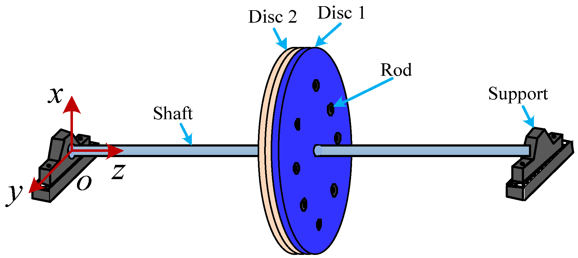
Figure 1. A rod fastening rotor with disc contact.
Applsci 13 05009 g001
Figure 2. Schematic diagram of an integrated rotor system.
Applsci 13 05009 g002
Figure 3. Schematic diagram of an equivalent model.
Applsci 13 05009 g003
Figure 4. Schematic diagram of contact between the rigid plane and single asperity.
Applsci 13 05009 g004
Figure 5. Variation of dimensionless normal contact stiffness due to different parameters: (a) dimensionless contact force F r * and (b) frequency index n .
Applsci 13 05009 g005
Figure 6. Relation between dimensionless normal stiffness K r * and fractal dimension D .
Applsci 13 05009 g006
Figure 7. Relationship between dimensionless normal contact stiffness K r * and characteristic length scale G .
Applsci 13 05009 g007
Figure 8. Relation between bending stiffness of interface K G and preload of bolt F p .
Applsci 13 05009 g008
Figure 9. Effects of the preload and frequency index on the natural frequency of the rod fastening rotor system.
Applsci 13 05009 g009
Figure 10. Effects of the fractal dimension D and characteristic length scale G on the natural frequency of the rod fastening rotor system.
Applsci 13 05009 g010
Table 1. Model parameters of the rough surface.
Fractal dimension D 1.34
Characteristic length scale G (m) 7 . 342 × 10 11
Grade of asperity n ( a ) 20 50
Equivalent elastic modulus E (GPa)115.4
Hardness H (GPa)6.1
Poisson’s ratio ν 0.3
Table 2. Main parameters of rotor system [36].
Disc mass m (kg)29.18
Disc radius R (mm)100
Shaft length L (mm)448.8
Shaft radius r (mm)30
Shaft elastic modulus E r s (GPa)210
Disclaimer/Publisher’s Note: The statements, opinions and data contained in all publications are solely those of the individual author(s) and contributor(s) and not of MDPI and/or the editor(s). MDPI and/or the editor(s) disclaim responsibility for any injury to people or property resulting from any ideas, methods, instructions or products referred to in the content.