You are currently viewing a new version of our website. To view the old version click .
Applied Sciences
  • Article
  • Open Access

4 April 2023

Patient–Robot Co-Navigation of Crowded Hospital Environments

and
Human-Machine Interaction & Innovation (HMI2) Lab, Santa Clara University, 500 El Camino Real, Santa Clara, CA 95053, USA
*
Author to whom correspondence should be addressed.
This article belongs to the Special Issue Advanced Human-Robot Interaction

Abstract

Intelligent multi-purpose robotic assistants have the potential to assist nurses with a variety of non-critical tasks, such as object fetching, disinfecting areas, or supporting patient care. This paper focuses on enabling a multi-purpose robot to guide patients while walking. The proposed robotic framework aims at enabling a robot to learn how to navigate a crowded hospital environment while maintaining contact with the patient. Two deep reinforcement learning models are developed; the first model considers only dynamic obstacles (e.g., humans), while the second model considers static and dynamic obstacles in the environment. The models output the robot’s velocity based on the following inputs; the patient’s gait velocity, which is computed based on a leg detection method, spatial and temporal information from the environment, the humans in the scene, and the robot. The proposed models demonstrate promising results. Finally, the model that considers both static and dynamic obstacles is successfully deployed in the Gazebo simulation environment.

1. Introduction

The nursing profession in the United States is critical to the provision of healthcare services and constitutes a large segment of the healthcare workforce. According to the US Bureau of Labor Statistics, the demand for nurses is expected to increase by 9% from 2020 to 2030 [1], driven by the increasing incidence of chronic diseases and the aging population’s need for healthcare services. The health and wellness (both physical and mental) of healthcare professionals, including nurses [2], are crucial to ensuring safe and high-quality healthcare delivery. A recent study [3] conducted across six countries highlights the relationship between nurse burnout and perceptions of care quality, emphasizing the importance of addressing the well-being of nurses in the healthcare system. Nurse burnout is a widespread phenomenon that can lead to decreased energy, increased fatigue, and a decline in patient care. According to Mo et al. [4], the COVID-19 pandemic has only exacerbated the situation, with nurses facing increased workloads, exposure to the virus, and the emotional stress of caring for patients in a high-stakes environment. Nurses shoulder a multitude of responsibilities, including the evaluation of a patient’s condition, documentation of medical histories, vital signs and symptoms, administration of treatments, collaboration with physicians and other healthcare practitioners, transfer or ambulation of patients, especially during post-surgery, and procurement of medical supplies. Addressing nurse burnout is essential to ensure the sustainability of the nursing workforce and to maintain safe and high-quality healthcare delivery. This can be achieved through a range of interventions, including providing adequate staffing levels, promoting work–life balance, and using robots. The utilization of robots for routine tasks, such as procurement of items or patient ambulation, allows for a reduction in the workload of nurses and enables them to concentrate on tasks that require their specialized knowledge and skills.
In recent years, to assist nurses with some of their routine tasks, with the advances in robotic technology and artificial intelligence (AI), robots have the potential to perform some of their routine tasks, which allows nurses to focus on actual patient care. In response to the COVID-19 pandemic, various robotic systems have been introduced to enhance hospital logistics, including disinfection of spaces and patient care [5,6]. These systems include robots that perform delivery tasks and object retrieval, reducing the need for human interaction in potentially contaminated areas and freeing up medical personnel to focus on more critical tasks [7], rehabilitation [8,9], walking assistance [10], and monitoring vital signs [11] that are essential components of patient care, which help improve patient outcomes and support the healing process. However, most hospitals cannot afford to acquire and assign specialized robots for each task. A unified robotic system that could cover a large range of hospital tasks is a potential solution. Accordingly, following the example of industrial applications utilizing multi-purpose robotic systems [12,13], a commercially available mobile manipulator could be reconfigured to assist nurses in a variety of tasks.
Our prior work [14,15,16,17] has presented a multi-purpose intelligent nursing assistant called MINA, which is a commercially available mobile manipulator and can assist with fetching objects, gait monitoring, and the possibility of teleoperation by the nurses. This paper aims to add additional functionality to MINA by enabling the robot to assist a patient in navigating safely in a hospital. It is assumed that the patient is able to walk with minimum support (e.g., a cane or a nurse holding their hand) and is required to walk for rehabilitation purposes with supervision (e.g., after surgery). However, hospital environments can be busy and tumultuous places, and their hallways can be crowded spaces filled with people moving around or sitting, chairs, carts, medical equipment, beds, etc. Therefore, a robotic walking assistant (RWA) must avoid collisions with humans or objects at all costs while maintaining physical contact with the patient that is assisted during walking. Naturally, the patient–robot co-navigation in these crowded environments can be a very challenging task.
Reinforcement learning (RL) [18] is a powerful technique for training deep learning models, particularly in scenarios where the model must learn to navigate a complex environment with obstacles. The key advantage of RL is its ability to identify the optimal path to take in the presence of obstacles and to generalize in unseen scenarios that may arise in a real-world environment. The ability to generalize is crucial for ensuring that the trained model can effectively navigate and respond to new and dynamic obstacles, making it a preferred method for training deep learning models in real-world applications.
This paper aims to utilize a multi-purpose mobile manipulator to assist patients while walking by safely guiding them through crowded hallways. The contribution of this paper is a proposed deep reinforcement learning-based framework that enables safe patient–robot co-navigation, including static and dynamic obstacle avoidance, by utilizing the speed of the patient’s gait and the information of the environment. The proposed framework is evaluated in a simulated environment, and the extended framework is successfully deployed in Gazebo, which is a realistic simulation environment. The frameworks and the environment are based on an open-source robot operating system (ROS) [19].
The rest of the paper is organized into the following sections; Section 2 discusses the related work, Section 3 defined the problem, Section 4 the proposed system for patient–robot co-navigation, and Section 5 presents and discusses the results. Section 6 concludes the work and discusses future directions of research.

3. Problem Statement

The hypothesis and significance of this research are that developing an intelligent multi-purpose robotic assistant, which can support and guide patients while walking, as well as help them maneuver obstacles in a crowded hospital environment using deep reinforcement learning models, could be a promising solution to assist nurses with non-critical tasks and enhance patient care. The primary objective of this work is to explore the development of a model architecture capable of providing adequate support to patients during walking tasks while also facilitating their ability to navigate through obstacles.
In patient–robot co-navigation, the goal is to guide a patient from one location to another while avoiding static obstacles, such as furniture, and navigating through crowds. The patient’s gait velocity in x- and y-directions, denoted as v p , x t and v p , y t at time t, respectively, can be affected by noise. To ensure safe navigation, a parameterized function must be created to output the optimal velocity for the robot based on the current environmental state and the patient’s gait velocity. The function should take into account the locations of the patient and obstacles (both static and dynamic), as well as the patient’s gait velocity. The robot should stop when the patient stops and guide the patient’s ambulation when in close proximity, safely leading the patient to the destination while avoiding collisions with any obstacles.
The representation of the position of the individuals in a crowd can be described mathematically as ( p c n , x t , p c n , y t ) , where n represents the index of the n t h human. The velocity of the robot is represented by v r , x t , v r , y t , and its heading angle is represented by β r t . Information on the static obstacles in the environment can be obtained using a LIDAR sensor, which can be encoded into an array i = 1 n L L i t , where n L is the number of obstacles and can be calculated by dividing the LIDAR’s angular coverage by its angular resolution. A multi-output parameterized function can be defined to model the relationship between the crowd, the robot, and the obstacles, as shown below in Equation (1):
v r , x t , v r , y t = f θ ( i = 1 n ( p c i , x t 1 p r x t 1 , p c i , y t 1 p r y t 1 ) , i = 1 n L L i , v p , x t 1 , v p , y t 1 , v r , x t 1 , v r , y t 1 , β r t )
The function f θ can be learned using reinforcement learning, where θ represents the set of parameters of the function. To handle the complexity of this massive model with multiple inputs, the learning process is divided into two stages. In the first stage, a reinforcement learning model, referred to as Model V1, is trained to consider only the dynamic obstacles. In the second stage, another reinforcement learning model with a similar architecture, referred to as Model V2, is trained to incorporate both dynamic and static obstacles. Finally, Model V2 is deployed in a realistic simulation environment Gazebo to test Model V2. For the development of the system, it is assumed that the patient can ambulate independently (does not fall) yet requires minimal assistance from the healthcare professionals, i.e., nurses. The manual muscle testing (MMT) [47] scale is a widely recognized method for assessing the strength of various muscle groups in patients. This scale assigns a numerical rating to each muscle group, ranging from 0 to 5, based on the patient’s ability to move against resistance. A rating of 4/5 indicates that the muscle group in question is capable of movement against resistance but with less than full strength. In the context of robotic assistance by the proposed RWA for patients, a minimum MMT score of 4/5 for both the arms and legs is recommended, but its usage must depend on the discretion of the physician. This can be considered one of the limitations. Therefore, the robot is intended to serve as additional support for individuals who need aid while walking.

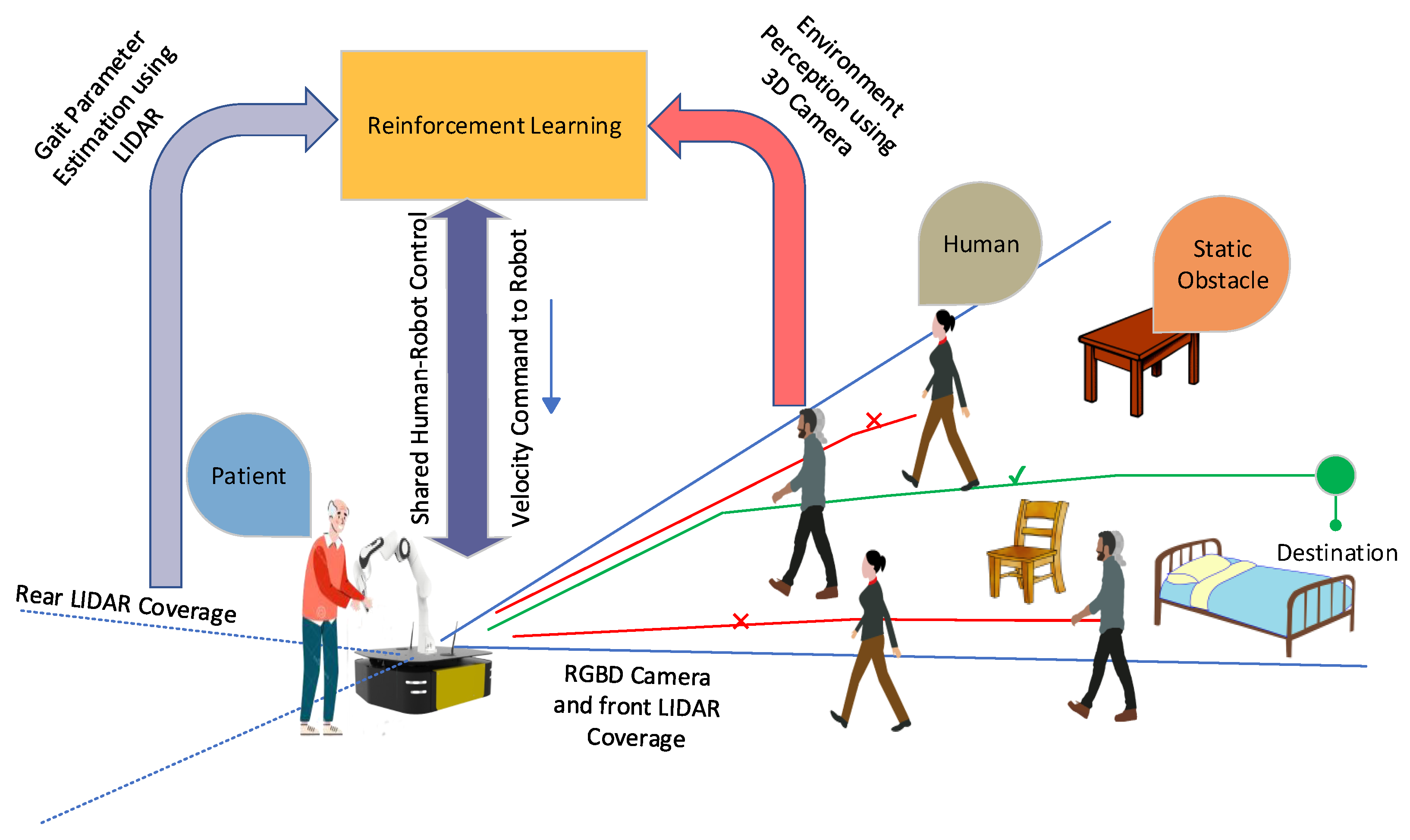
4. Proposed System for Patient–Robot Co-Navigation

This section presents the proposed system for the patient–robot co-navigation and its architecture. The main task of the system is to help ambulate the patient in a crowded environment, e.g., a hospital. The proposed system is considered an RWA as it provides assistance during the patient’s walking; the system supports the patient in avoiding static and dynamic obstacles.
The hardware setup of the RWA, shown in Figure 1, consists of an omnidirectional mobile base (Clearpath Ridgeback) and a 7-DOF robotic arm (Franka Emika Panda). The mobile base is equipped with two LIDARs, i.e., one on the front and one on the rear of the mobile base. An RGB-D camera (Intel Realsense D435i) is mounted on the mobile base. The mobile base and robotic arm can be substituted with any other robot of choice equipped with similar sensors.
Figure 1. The hardware setup of the multi-purpose robotic system.
An overview of the proposed architecture for the RWA system is shown in Figure 2. First, the RWA system detects the patient’s legs and estimates their position. It is assumed that the patient walks at the rear of the robot. The robotic arm is configured and locked in a specific manner, as depicted in Figure 1, to facilitate patient support. This configuration is designed to ensure that the robot remains stable and secure while providing the necessary assistance to the patient. If the patient is close to the rear of the robot and starts walking, the RWA detects and estimates the leg’s position and then estimates the gait velocity. Subsequently, the RWA starts moving with the same velocity as the patient’s gait velocity. At the same time, the data from the RGB-D camera and front LIDAR are used to perceive the environment by recognizing static (e.g., chairs, beds, tables, walls) and dynamic (e.g., humans, moving objects) obstacles. The data from environmental perception, the patient’s gait parameters, and the robot’s parameters (current robot pose and robot’s goal pose) are the inputs to a reinforcement learning (RL) module. The RL module outputs the robot’s velocity, factoring in the shared control properties between the robot and the patient. It is assumed that the final goal of the patient is known to the robot. For example, the patient may need to perform the 3 m and 6 m walk tasks defined by a nurse or a therapist. Since the task is known to the robot and the patient, both will require to work together to reach the goal. In the consequent subsections, the patient’s leg detection, gait velocity estimation, and shared control in crowd environments using RL are presented in detail.
Figure 2. Overview of the patient–robot co-navigation framework.

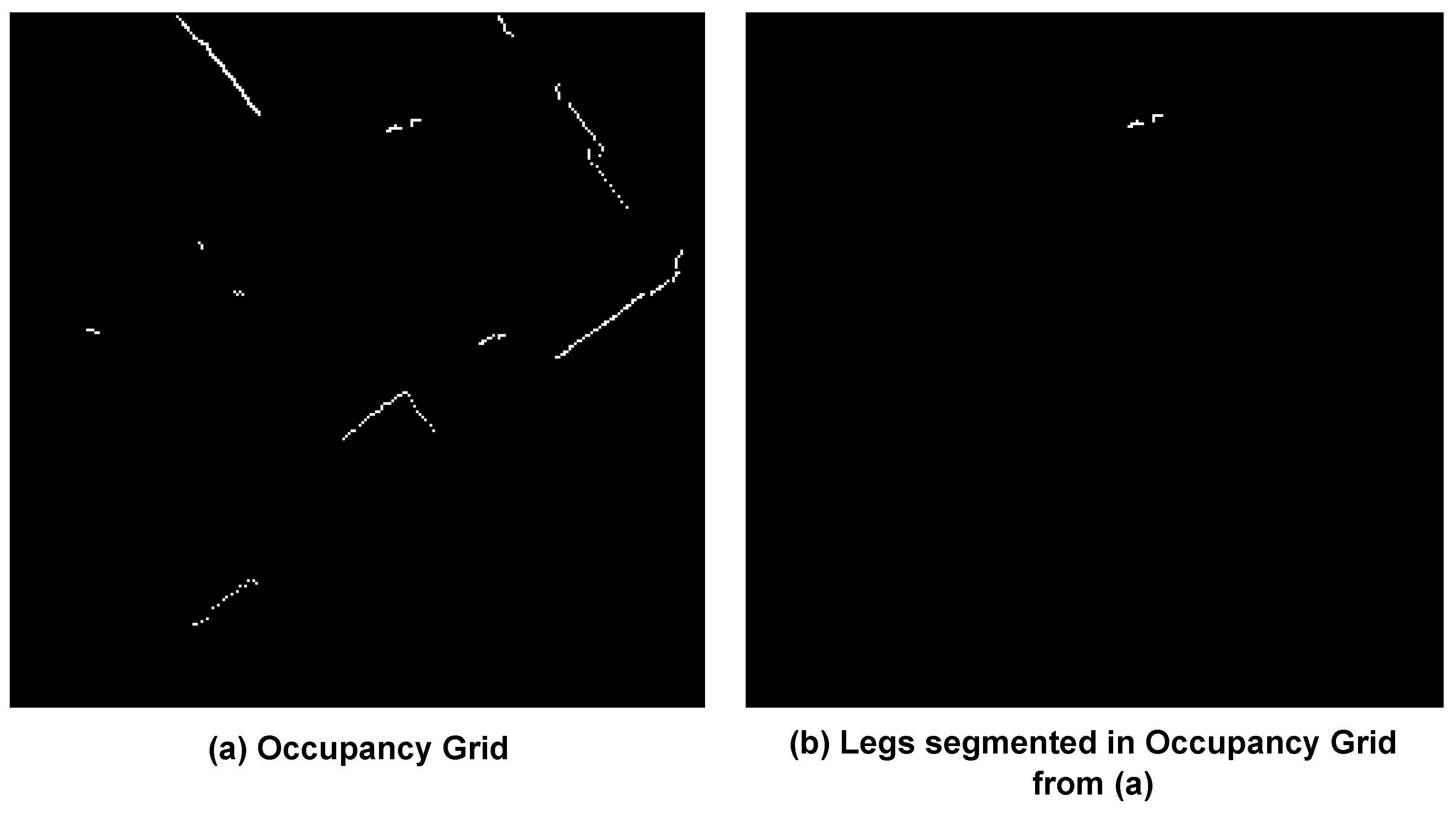
4.1. Leg Detection and Gait Velocity Calculation

The first step of our system is to detect the legs of the patient using the data from the rear laser scanner and then to calculate the gait velocity of the patient. Our prior work [15] presented a convolutional neural network (CNN)-based method to detect the legs. This method uses a U-Net architecture [48], which is a fully convolutional network developed predominantly for image segmentation tasks and works with fewer training data. The data from the laser scanner are transformed into a binary grayscale image, and it is called the occupancy grid image (shown in Figure 3a). The occupancy grid includes critical information about the environment, such as the patient’s legs, walls, and other obstacles. The U-Net is trained on leg segmentation from the dataset provided by Aparicio et al. [49], which consists of laser scanner data and segmented leg positions. The U-Net segments all the legs in the scene, but only the one closer to the robot’s rear is considered the patient. Let the position of the segmented legs be the vector L p with respect to the coordinate system of the laser scanner {L} (shown in Figure 1). It is important to compute the position of the segmented legs with respect to the coordinate system of the robot’s base {R} (shown in Figure 1). The transformation matrix L R T of the coordinate system {L} with respect to the coordinate system {R} is known. The position of the segmented legs R p with respect to the coordinate system {R} is calculated by Equation (2).
R p = L R T · L p
Figure 3. (a) Occupancy grid from LIDAR data; (b) leg detection from our prior work (right) [15].
The final step is to use the position of the legs calculated in the robot’s coordinate frame as input to an extended Kalman filter [50], which outputs the patient’s gait velocity. The patient’s gait velocity is then used by the reinforcement learning method, which is discussed in the next subsection.

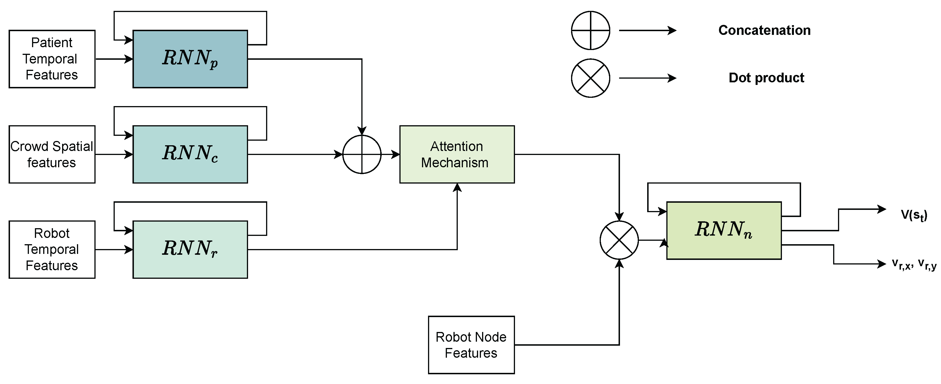
4.2. Shared Control in Crowded Environments Using Reinforcement Learning

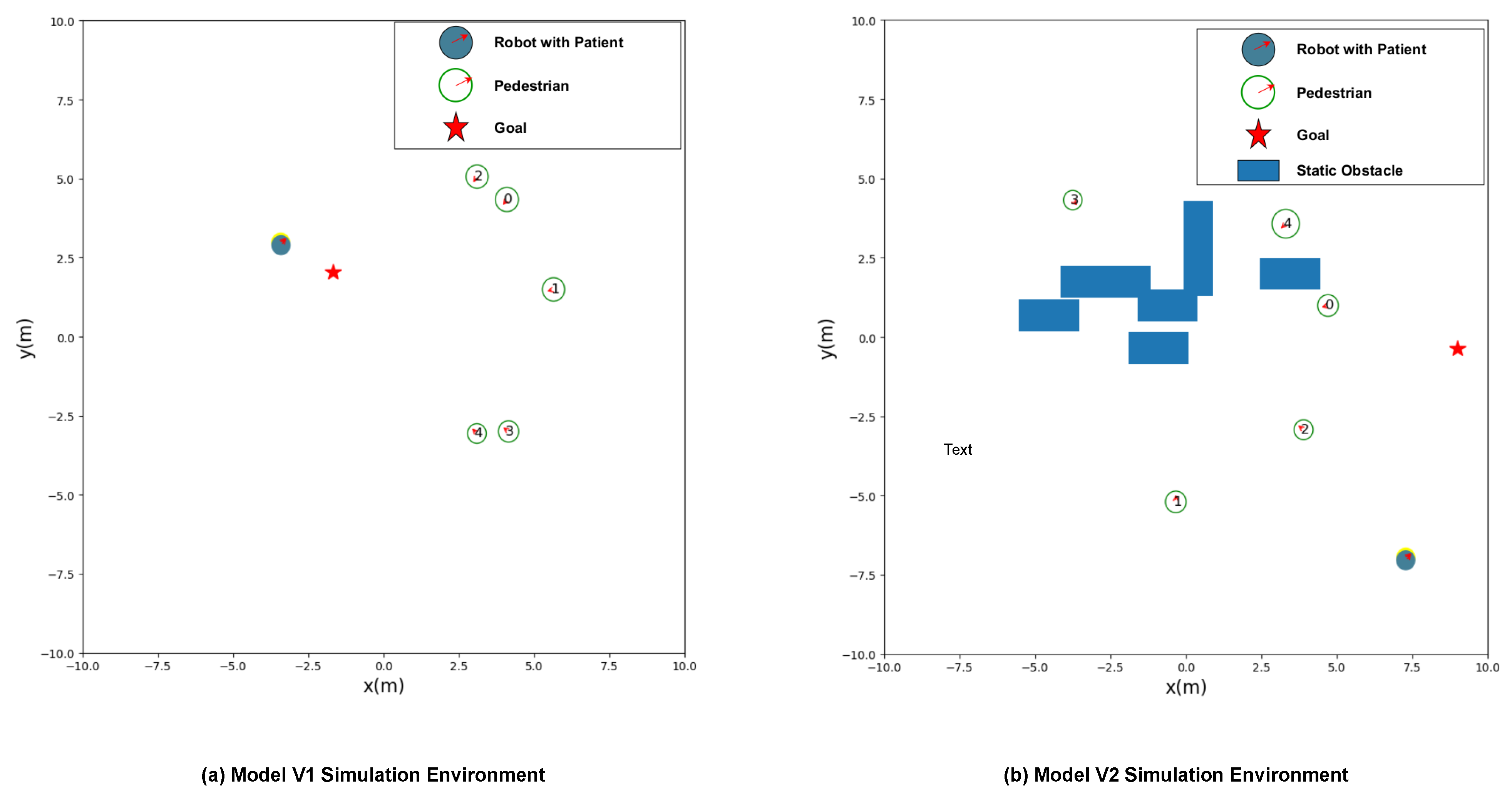
4.2.1. Shared Control Considering Only Dynamic Obstacles (Model V1)

Shared control between the patient and the robot is crucial for two reasons: (i) the robot needs to adjust its speed according to the patient’s gait velocity to maintain interaction with the patient, and (ii) the robot needs to navigate the patient safely through the crowded environment. In the proposed work, RL is used to achieve shared control between the robot and the human. RL methods are already used to enable robots to navigate, as mentioned in Section 2.2; however, the robots do not have physical interactions with humans.
In the presented work, a deep RL architecture is proposed, which extends the crowd navigation capabilities of the network architecture proposed by Liu et al. [43], where st-graph is used, and each factor of st-graph observes node and edge features at each time step. Figure 4 shows our network architecture and consists of four recurrent neural networks (RNNs), where each is a factor graph representation of the st-graph; (i) crowd spatial edge R N N c , (ii) patient temporal edge R N N p , (iii) robot temporal edge R N N r , and (iv) node R N N n .
Figure 4. Proposed framework for the patient–robot co-navigation in environments with dynamic obstacles (Model V1).
The R N N c grasps the spatial interactions between each detected human in the crowd and the robot. The spatial interactions at a particular time (t) can be represented as a list of distances from each human to the robot, which can be represented as i = 1 n ( p c i , x p r x , p c i , y p r y ) , where ( p c n , x , p c n , y ) are the 2D coordinates of the nth human with respect to the robot’s base coordinate system ( p r , x , p r , y ) . The R N N r captures the relationship between the temporal dependency of the robot’s velocity and the spatial crowd. To learn the temporal dependency, the temporal features of the robot, which are the corresponding location and velocities of the robot in the x and y direction, denoted by ( p r , x , p r , y , v r , x , v r , y ) , are used as input so that the RNN can learn to adjust its trajectory from the initial starting point to the goal. The goal coordinates are denoted by ( g r , x , g r , y ) ; the radius and heading direction of the robot are denoted by ρ r o b o t and θ , respectively. The ρ r o b o t in our case is set to 1.21 m, which is the radius of the Clearpath Ridgeback robot, 0.96 m + 0.25 m, which is the boundary of the robot. The R N N p captures the temporal dynamics between patient gait velocity and the robot. In order to implement the shared control between the patient and the robot, this RNN takes the patient’s gait velocity in x and y directions, which can be represented as ( v p , x , v p , y ) .
The outputs of R N N r , R N N c , and R N N p are required to be combined in such a way that the importance of each RNN output at that particular instance is known. For example, if the patient is close enough to the robot but very close to another human, at that instance, the highest priority of the robot should be to move away from the human. Similarly, if the humans are far from the robot but the robot is moving away from the patient at that instance, the robot should decrease its velocity so that the patient will not lose contact with the robot. An attention mechanism is used to teach the model to recognize these traits from the inputs and adjust accordingly to the robot’s velocity. The attention mechanism proposed by Vaswani et al. [51] is used in this framework. For humans in the environment, let the output of the R N N c at a given time t be [ s c 1 t , s c 2 t , s c 3 t , , s c n t ] , where c i denotes the ith human. Similarly, let the output of the R N N p be s p t at a given time t. V t can be defined as the concatenation of the outputs of R N N c and R N N p , which are [ s c 1 t , s c 2 t , s c 3 t , , s c n t , s p t ] . Let the output of R N N r be s r t . The attention mechanism assigns relative weights to the inputs, which means that the attention mechanism determines the inputs that it should focus on. The first step is that the inputs V t should be projected into an embedding space. This is computed by multiplying it with the matrix W Q , and the output of the multiplication is Q t . s r t is the output of R N N r , whose inputs are ( p r , x , p r , y , v r , x , v r , y ) , i.e., the current position and velocity of the robot. The task is to calculate the relative importance of each human and patient by assigning weights to each of them. For example, if a human moves very close to the robot, the human should obtain a higher weight than other pedestrians. Likewise, if the patient is moving away from the robot, then the patient needs to be given a higher weight so that the robot adjusts its path and is in the vicinity of the robot. Therefore, s r t is multiplied with matrix W K to convert it to the embedded space, and the output of the multiplication is K t . The attention is calculated as shown in Equation (3), where a l p h a t represents the relative weights of the human and patient data that the model should immediately give attention to, and att t is the re-weighted V t .
Q t = V t W Q , K t = s r t W K , α t = softmax 1 n + 1 Q t K t att t = V t α t .
Both W K and W Q are learned while training the model. The output of the attention module is att t . This weighted vector att t is concatenated with the robot node features x t = [ p r , x , p r , y , v r , x , v r , y , g r , x , g r , y , v r , m a x , θ , ρ r o b o t ] and passed as input to the final node RNN R N N n . The output of this RNN is o t ; which is defined in the Equation (4) shown below:
o t = R N N n ( o t 1 , [ att t , x t ] )
Subsequently, the output o t is passed through a fully connected layer, resulting in the determination of both the value function V ( s t ) and the policy distribution π ( a t | s t ) . The value V ( s t ) is the model’s projected value function for how good a state s t is for the robot to be in. π ( a t | s t ) is the action that the robot should take given a state s t , which in our case is the velocity the robot should take, which is v r , x , v r , y . The total number of trainable parameters for this model is 613294.
The crowd navigation and shared control can be formulated into a reinforcement learning problem in the following way: A robot interacting with the environment can be modeled as an episodic Markov decision process (MDP). Assuming the whole environment starts from a random initial state at time t = 0, at every discrete point in time, denoted as t, the robot operates by selecting an action, a t , based on its policy function, π ( a t | s t ) . The policy maps the current state, s t , to a probability distribution over the set of possible actions, from which the robot selects its action, where s t denotes the states of the whole environment (robot, humans, and patients). As a result of executing its chosen action, the robot receives a reward and transitions to the next state. The state transition and reward represent the consequences of the action taken in the current state and serve as the basis for the robot’s decision-making process in the subsequent time step. Let μ t be the reward the robot has for transiting the state s t to s t + 1 and the γ be the discount factor, the total expected reward until the episode ends would be μ = k = 0 ( γ k μ k ) , where k is the total number of time steps. An episode includes all of the timesteps from the start until the robot reaches the goal. To ensure that the model learns a policy of shared control and crowd navigation, the proximal policy optimization (PPO) RL algorithm proposed by Schulman et al. [52] is used. the loss function used in PPO is a combination of the clipped surrogate objective and the entropy bonus as proposed by Schulman et al. The reward function μ k proposed by Liu et al. [43] is modified to include the co-navigation objectives of our system, and it is as follows:
μ k = 20 d m i n t < 0 20 d p , r t > 0.25 2.5 ( d m i n t 0.25 ) 0 < d m i n t < 0.25 10 d g o a l t < ρ r o b o t 2 ( d g o a l t + d g o a l t 1 ) o t h e r w i s e
At each time step (t), d m i n t represents the smallest possible distance between the robot and any individual who is not the patient (i.e., any human excluding the patient) at that time. The reward function is designed to incentivize the robot’s behavior toward reaching its goal while avoiding collisions with humans and maintaining contact with the patient. The distance between the robot and the goal, d g o a l t , and the distance between the robot and the patient, d p , r t , are used as features in the reward function. The robot is rewarded for reducing d g o a l t and penalized for increasing d p , r t when it is close to humans or too far away from the patient. The robot is also punished for moving away from the patient beyond a certain threshold distance. The objective of the reward function is to lead the robot to move toward its target while ensuring the preservation of a secure separation from human entities and maintaining physical contact with the designated patient. If d p , r t is less than 0.25 m, it is considered that the robot and the patient are in contact. In accordance with the prescribed metric for the successful completion of the robot’s objective, denoted as d g o a l t < 0.25 m, a reward of 10 is granted. This incentive scheme aligns with the assertion of Sutton et al. [53], i.e., reward structures with steep gradients are effective in shaping certain behaviors, both positively and negatively. To this end, a punitive penalty of −20 is imposed as a negative reward for undesirable actions, while a positive reward of 10 is granted for accomplishing the desired objective. Notably, the reward for collision with objects is substantially more punitive, as collisions in the real world can lead to severe consequences. Consequently, the collision with objects is met with a steeply negative reward.
The proposed model architecture encourages learning from the spatial and temporal features, and the reward function used in training by PPO enforces the rules of shared control and co-navigation. However, this model only focuses on dynamic obstacles. In the next subsection, this proposed model architecture is extended to include static obstacles as well.

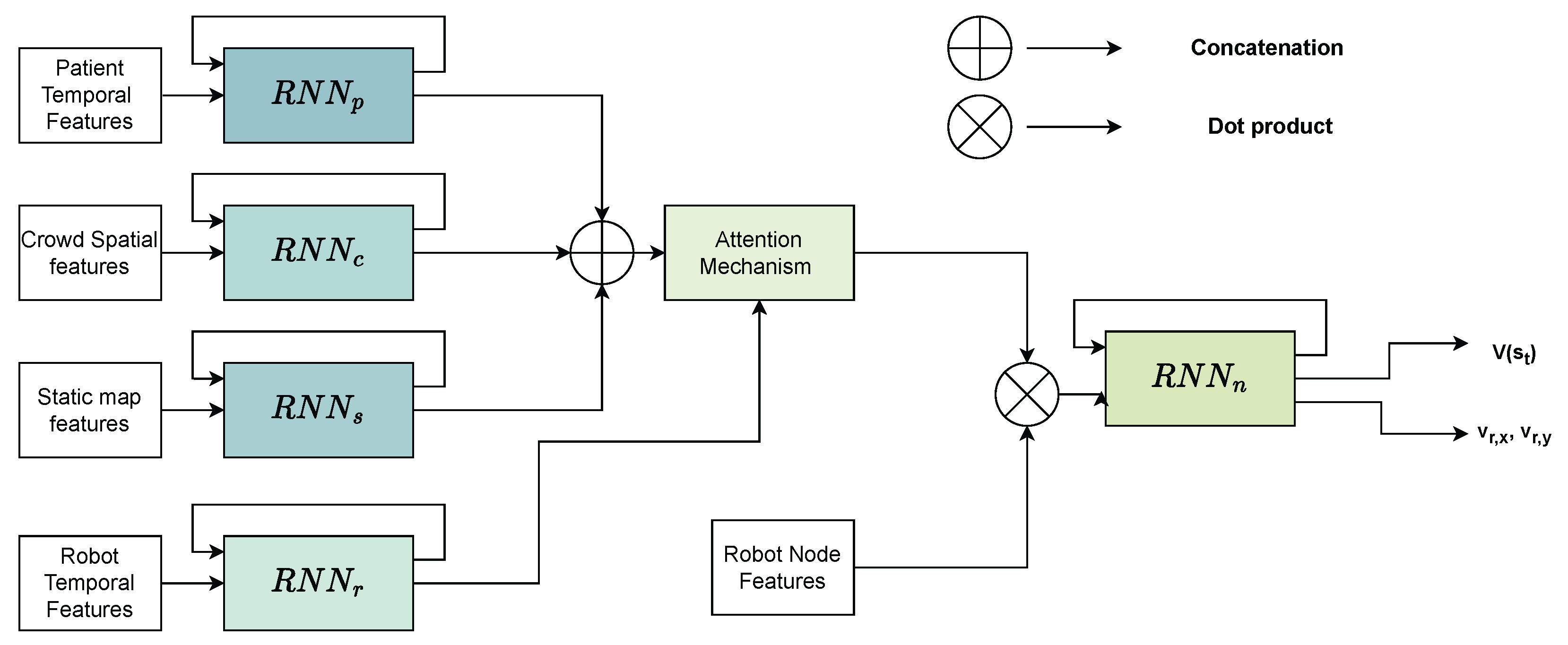
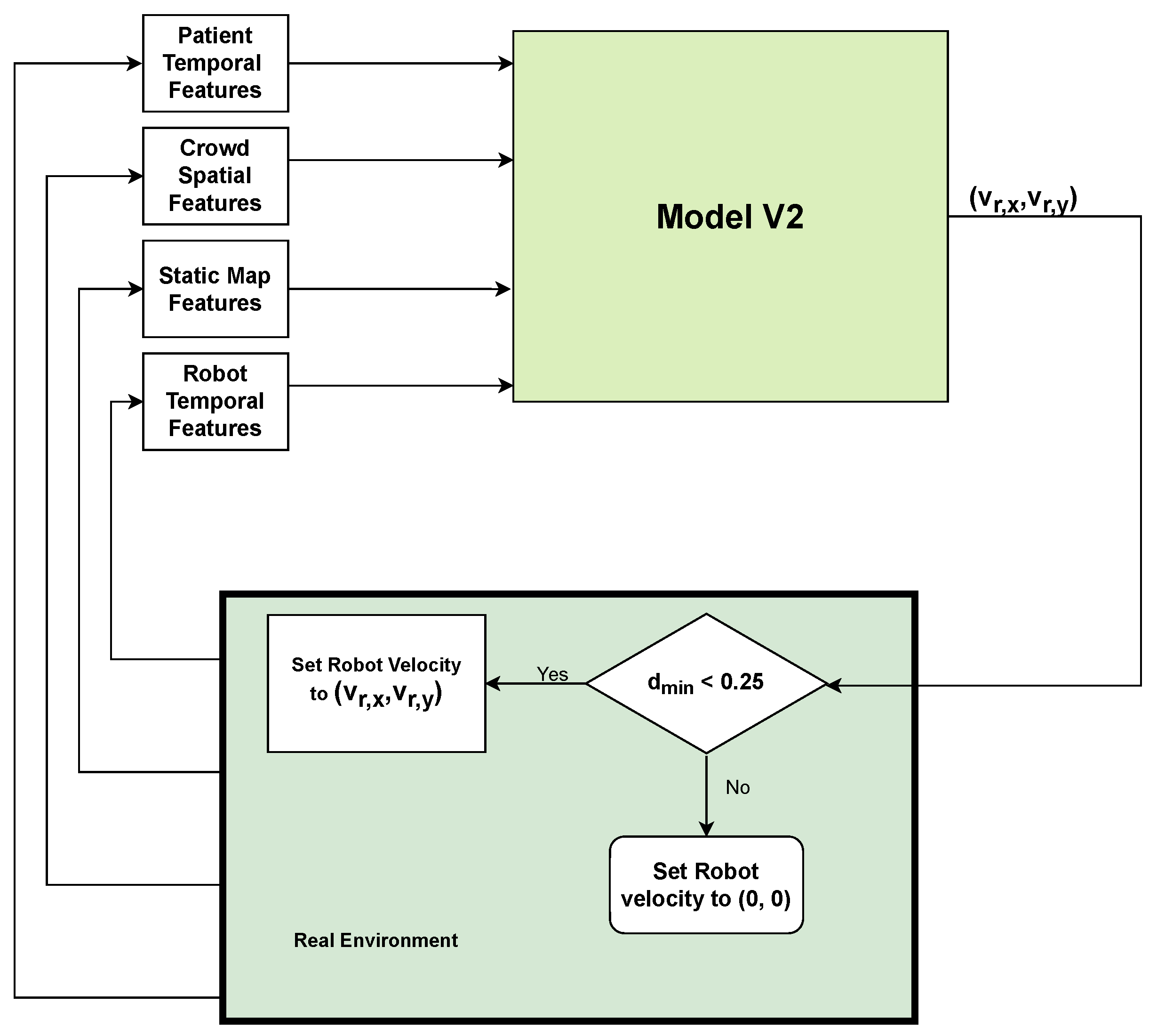
4.2.2. Shared Control Considering Dynamic and Static Obstacles (Model V2)

In the previous section, the proposed model architecture in Figure 4 only takes into consideration dynamic obstacles, such as humans. However, in practical cases, there are static obstacles, such as walls, tables, etc., which the robot needs to avoid. Therefore, the proposed architecture is extended to consider both static and dynamic obstacles. Figure 5 shows the modified architecture where a block called “Static map features” is added. This block comprises the field of view (FOV) of the laser scanner data that shows all of the nearby obstacles ( i = 1 n L L i t ). These laser scanner data are used as input for the R N N s . The output of R N N s is concatenated with the outputs of R N N p and R N N c (instead of just R N N p and R N N c in the case of dynamic obstacles only), and are provided as input to the attention mechanism. The rest of the architecture remains the same as the proposed architecture in Section 4.2.1. The modified architecture is shown in Figure 5. The total number of trainable parameters for this model is 766617. However, as the modified architecture needs to avoid static obstacles, the reward function in Equation (5) needs to be updated to include punishment for when the robot hits the static obstacles. Equation (6) shows the updated reward function, where the shortest distance between the robot and any obstacle is defined as d o t .
μ k = 20 d m i n t < 0 20 d p , r t > 0.25 20 d o t < 0.3 2.5 ( d m i n t 0.25 ) 0 < d m i n t < 0.25 10 d g o a l t < ρ r o b o t 2 ( d g o a l t 1 d g o a l t ) o t h e r w i s e
Figure 5. Proposed framework for the patient–robot co-navigation in environments with dynamic and static obstacles (Model V2).
The modified architecture can enable the robot and the patient to avoid both static and dynamic obstacles. The next section discusses the simulation environment used to train the model using PPO RL and the results between prior work and the proposed frameworks.

5. Experimental Evaluation

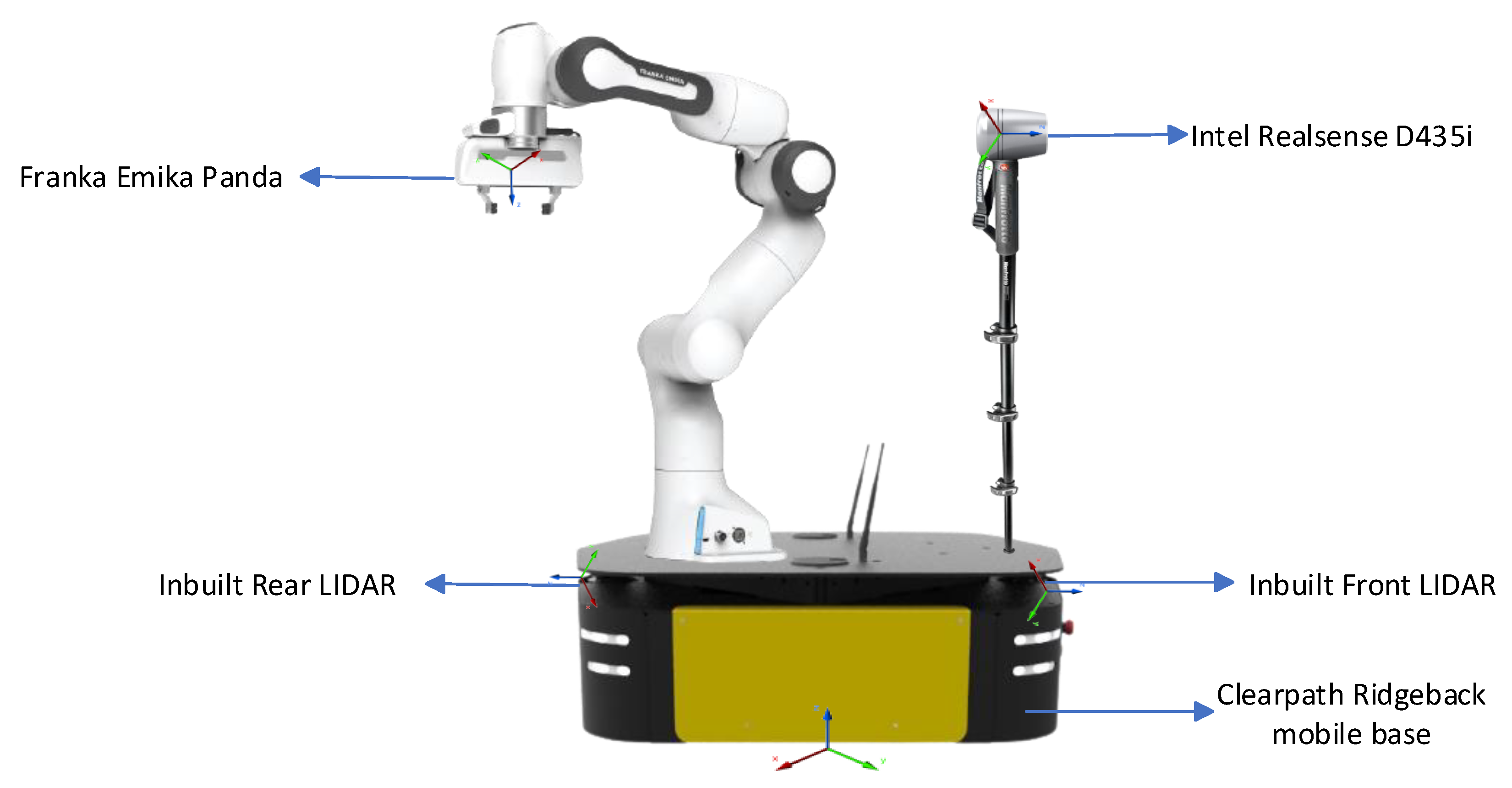
5.1. Experimental Setup

A simulation environment is required to train the RL model to learn the shared control principles. As our framework requires a patient who walks together with a robot, the simulation environment proposed by Liu et al. [43] is updated to include this functionality. The patient walks behind the robot with a gait velocity in x and y directions ( v p , x , v p , y ). Initially, the robot and patient are initialized, such that the distance between them is less than 0.25 m to ensure that they are in contact.A random goal, different from the initial starting point, is selected as the target that the robot must navigate the human to. Then, the patient’s gait velocity is simulated as follows:
v p , x = v r , x + N ( 0 , 1 ) v p , y = v r , y + N ( 0 , 1 )
where the notation N ( 0 , 1 ) represents a normal distribution with a mean of 0 and standard deviation of 1 meter per second. This distribution is commonly used to model random variables that are centered around 0 and have similar magnitudes. In this case, it could be used to model the random fluctuations in the patient’s velocity. The selection of the standard deviation value is based on the limits specified by Joosse et al. [46], in that the speed of a robot approaching a human should not be more than 1 m/s. As the robot adjusts to the speed of the patient, the patient’s velocity should not be more than 1 m/s to adhere to social norms. Adding a normal noise to the velocity components simulates the real-world scenario where the tracked gait velocity is not in the same direction or magnitude as the robot, but it would be nearly equal. Finally, after each time step, the positions of each human i in the scene ( p c i , x , p c i , y ), the robot ( p r , x , p r , y ), and the patient ( p p , x , p p , y ), respectively, are updated based on Equation (8).
p c i , x [ t + 1 ] = p c i , x [ t ] + v c i , x [ t ] Δ t p c i , y [ t + 1 ] = p c i , y [ t ] + v c i , y [ t ] Δ t p r , x [ t + 1 ] = p r , x [ t ] + v r , x [ t ] Δ t p r , y [ t + 1 ] = p r , y [ t ] + v r , y [ t ] Δ t p p , x [ t + 1 ] = p p , x [ t ] + v p , x [ t ] Δ t p p , y [ t + 1 ] = p p , y [ t ] + v p , y [ t ] Δ t
Figure 6 shows simulation environments used to train the presented framework for co-navigation with only dynamic obstacles (Model V1) and with both static and dynamic obstacles (Model V2). Nvidia RTX 3090 was utilized for training both V1 and V2 models, with each model requiring 16 hours to complete 1000 epochs of training. In the following subsection, the experimental results are presented and discussed.
Figure 6. RL simulation environment for the patient–robot co-navigation training.

5.2. Experimental Results

To evaluate our model (V1), which considers only dynamic obstacles, we compare its performance with the baseline method DSRNN [43] (Table 1). We also compare our second model (V2), which considers both static and dynamic obstacles, with the baseline method SOADRL [42] (Table 2). The following metrics have been defined: (i) success rate, (ii) timeout rate, (iii) collision rate, (iv) contact loss rate, and (v) navigation time. In relation to the present system, it was imperative to assess the safety and temporal demands associated with patient mobility. Consequently, we incorporated various metrics, such as contact loss rate to ensure sustained grip of the robotic arm by the patient, navigation time to gauge the duration required to complete the walking task, timeout rate to prevent the reinforcement learning algorithm from learning inefficient policies that prolong short distance coverage, collision rate to evaluate the safety of robot navigation around obstacles, and lastly, success rate to comprehensively assess the system’s overall performance. The success rate is the percentage of trials in which the robot reaches the goal without collisions with other humans while keeping contact with the patient. The timeout rate is the percentage of trials that require more than 100 timesteps for the robot to reach the goal. The collision rate is the percentage of trials where the robot collides with a human, and the contact loss rate is the percentage of trials where the robot moves away from the patient, and the contact is lost. The lower the contact loss rate, the better the model supports the patient throughout the trial. Finally, the navigation time is the time (in seconds) that the robot is required to reach the goal from the start.
Table 1. Comparison between the baseline model [43] and the proposed model V1 with FOV 70 .
Table 2. Comparison between the baseline model SOADRL [42] and the proposed model V2 with FOV 70 .

5.3. Discussion

The performances of Model V1 and Model V2 were evaluated under a limited field of view (FOV) of 70 , with varying numbers of human obstacles present. A total of 50 trials were conducted for each configuration, and the results were recorded and analyzed.
In Table 1, the metrics from model V1, which maneuver around dynamic obstacles, are compared to their respective baseline. The parameters are the dynamic collision rate, contact loss rate, timeout rate, success rate, and navigation time. In Table 2, the metrics from model V2, which maneuver around both static and dynamic obstacles, are compared to their respective baseline. It was found that as the number of humans in the scene increased, the success rate of the models decreased. The proposed model demonstrates superior collision rates when compared to the baseline models, with the exception of Model V2 when it was tested with 10 humans and static obstacles (as opposed to 2–7 humans and static obstacles in the baseline model). Despite achieving a better collision rate when navigating around dynamic objects, the collision rate for static objects was observed to be higher. This phenomenon can be attributed to the increased number of humans present in the environment, thereby highlighting the impact of human presence on collision rates. However, it is imperative to acknowledge that the contact loss rate is a parameter that solely pertains to our model and, hence, renders any comparison of a success rate with respect to baselines unfeasible. Therefore, to ensure a fair comparison, the success rate is considered as the subtraction of the sum of the object collision rate (dynamic for V1, dynamic and static for V2) and the timeout rate from 100.
It is obvious from the experimental results that the success rate surpasses that of the baseline methods. There is the concept that contact loss refers to the scenario where the distance between the robot and the patient exceeds 25 cm from our reward function mentioned in Equations (5) and (6), which is less than the average arm length of an individual. This parameter has been established to create a secure environment for the patients, such that if they desire to abruptly halt the robot, it would instantaneously come to a stop while still being grasped by the patient’s hands. Finally, Model V2 was implemented in the Gazebo simulation environment to assess its ability to assist patients and avoid obstacles, which is further discussed in the subsequent section of the research.

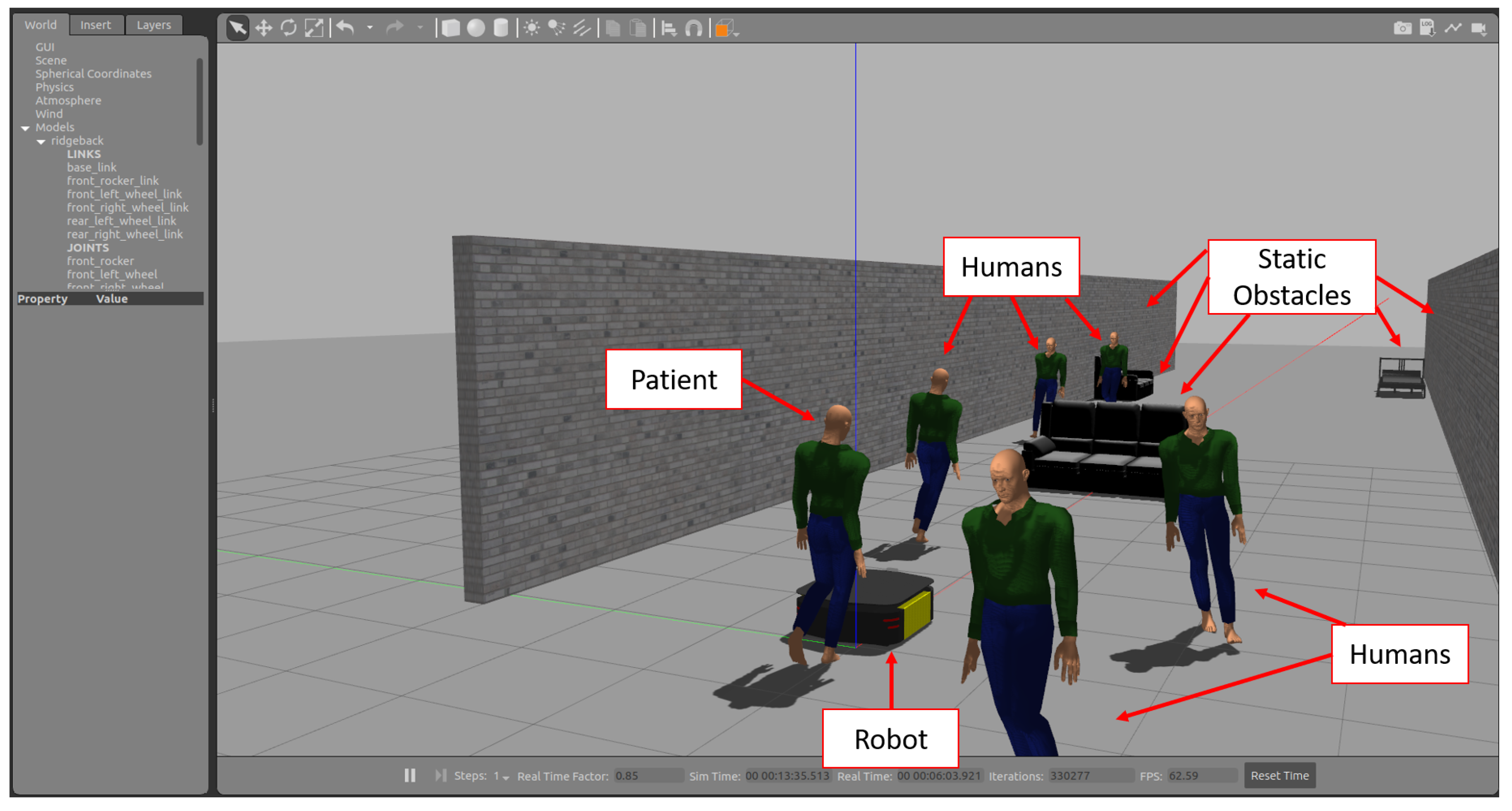
5.4. Simulation Using Gazebo

For gait tracking and crowd maneuvering, a test environment in Gazebo [54] was developed, as shown in Figure 7. The developed simulation mimics a real-world scenario of a patient walking behind a robot amidst a crowd and evaluates the robot’s ability to assist the patient. The crowd is simulated using the social force model to model crowds [55]. First, the patient can gradually walk at their own speed toward the robot. Then, the robot senses the patient and prepares to assist the patient. Finally, once the patient is near the robot and starts using it as support, they co-navigate to the destination avoiding both the crowd and any other static obstacles, such as furniture that obstruct the path. The patient’s velocity is sensed using the LIDAR leg detector U-Net model, as discussed in Section 4.1. An Intel Realsense D435i camera is loaded to the front of the robot, which uses Yolov5 [56] to detect humans and track them. The front laser actively scans for any obstacles in the environment. The patient’s gait velocity, pedestrian spatial information, front laser readings, and the robot’s current state are inputted into the RL model V2 (explained in Section 4.2.2). The model outputs the velocity values that need to be set on the robot.
Figure 7. Human–robot co-navigation in Gazebo.
The model also outputs a predicted action value. The action value of the robot determines how good it is for the robot to be in a particular state or to do a certain action in that state. The concept of “how good” is described in terms of projected future rewards or, to be more accurate, expected returns. This video https://youtu.be/LqCMkvKuM8E, (accessed on 30 March 2023) shows the model V2 controlling the robot in Gazebo. On the left side, a terminal is shown that constantly prints the action value predicted by the model. Initially, when the robot faces an obstacle and moves toward the obstacle, the action value is negative. However, once the robot adjusts its path and avoids the furniture, the values are positive. The robot is able to reach its goal without losing contact with the patient. As evident from the data presented in Table 1 and Table 2, the contact loss rate of model V2 is not always zero. This highlights the importance of implementing measures to prevent contact loss, such as stopping the robot when the distance between the robot and the patient exceeds a certain threshold, such as 0.25 m. A flowchart illustrating the control system of the robot, including this safety feature, is depicted in Figure 8.
Figure 8. Flowchart of how the Model V2 is used to control the robot in a realistic Gazebo simulation.
Due to the COVID-19 pandemic and its impact on real-world robotic studies [57], a real-world evaluation is not yet possible. Our goal, in the future, will be to evaluate our models in a real-world lab environment to ensure safety, and then in a hospital environment. It is also important to note that recent findings have shown that deep learning models may lead to incorrect behaviors if the data that are trained on are sparse [58]. As robot navigation may have to deal with sparse and noisy data in the real world, we plan to evaluate the correctness of the behavior of our RL-based framework.

6. Conclusions and Future Work

The paper proposes a shared control framework that integrates both spatial and temporal considerations into the decision-making process of a robot for navigating in a crowd and providing walking support to a patient. The presented work addresses the gap between robotic crowd navigation and robotic walking assistance. Our proposed models enable co-navigation between a patient and a robot. Two models are proposed and evaluated; the first model enables the patient–robot co-navigation in environments with dynamic obstacles, and the second enables co-navigation in environments with static and dynamic obstacles. Both models were evaluated and compared with baseline methods with respect to collision rates. The first model outperforms the baseline model with respect to collisions with humans. In contrast, the second model outperforms the baseline model with respect to both the success rate and collisions with humans. Additionally, the results show that our models can maintain contact with the patient. Finally, our model, which avoids both dynamic and static obstacles, was implemented in Gazebo successfully. This is a promising step towards deploying the model on a real-world mobile platform. As of now, our system is designed to assist patients with a minimum MMT level of 4/5. Our next step will be to evaluate our model in a real-world laboratory setting (e.g., a crowded hallway at our university) and then in a clinic or hospital setting. We are also interested in extending our work to other environments where co-navigation may be needed. Additionally, we plan to expand the system to accommodate patients with a lower rating than 4 for rehabilitation purposes.

Author Contributions

Conceptualization, M.K. and K.K.; methodology, K.K and M.K.; software, K.K.; experiments, K.K.; formal analysis, M.K. and K.K.; writing—original draft preparation, M.K. and K.K.; writing—review and editing, K.K. and M.K.; supervision, M.K.; project administration, M.K.; funding acquisition, M.K. All authors have read and agreed to the published version of the manuscript.

Funding

This material is based upon work supported partially supported by the National Science Foundation under Grant Number 2226165.

Institutional Review Board Statement

Not applicable.

Data Availability Statement

Not applicable.

Acknowledgments

The authors would like to acknowledge Manizheh Zand for the fruitful discussions about the project.

Conflicts of Interest

The authors declare no conflict of interest.

References

  1. U.S. Bureau of Labor Statistics. Occupational Employment and Wages. Available online: https://www.bls.gov/ooh/healthcare/registered-nurses.htm (accessed on 2 February 2023).
  2. Hall, L.H.; Johnson, J.; Watt, I.; Tsipa, A.; O’Connor, D.B. Healthcare staff wellbeing, burnout, and patient safety: A systematic review. PLoS ONE 2016, 11, e0159015. [Google Scholar] [CrossRef] [PubMed]
  3. Poghosyan, L.; Clarke, S.P.; Finlayson, M.; Aiken, L.H. Nurse burnout and quality of care: Cross-national investigation in six countries. Res. Nurs. Health 2010, 33, 288–298. [Google Scholar] [CrossRef] [PubMed]
  4. Mo, Y.; Deng, L.; Zhang, L.; Lang, Q.; Liao, C.; Wang, N.; Qin, M.; Huang, H. Work stress among Chinese nurses to support Wuhan in fighting against COVID-19 epidemic. J. Nurs. Manag. 2020, 28, 1002–1009. [Google Scholar] [CrossRef] [PubMed]
  5. Kaiser, M.S.; Al Mamun, S.; Mahmud, M.; Tania, M.H. Healthcare robots to combat COVID-19. In COVID-19: Prediction, Decision-Making, and Its Impacts; Springer: Berlin/Heidelberg, Germany, 2021; pp. 83–97. [Google Scholar]
  6. Javaid, M.; Haleem, A.; Vaish, A.; Vaishya, R.; Iyengar, K.P. Robotics applications in COVID-19: A review. J. Ind. Integr. Manag. 2020, 5, 441–451. [Google Scholar] [CrossRef]
  7. Kyrarini, M.; Lygerakis, F.; Rajavenkatanarayanan, A.; Sevastopoulos, C.; Nambiappan, H.R.; Chaitanya, K.K.; Babu, A.R.; Mathew, J.; Makedon, F. A Survey of Robots in Healthcare. Technologies 2021, 9, 8. [Google Scholar] [CrossRef]
  8. Qassim, H.M.; Wan Hasan, W. A review on upper limb rehabilitation robots. Appl. Sci. 2020, 10, 6976. [Google Scholar] [CrossRef]
  9. Shi, D.; Zhang, W.; Zhang, W.; Ding, X. A review on lower limb rehabilitation exoskeleton robots. Chin. J. Mech. Eng. 2019, 32, 1–11. [Google Scholar] [CrossRef]
  10. Nomura, T.; Kanda, T.; Yamada, S.; Suzuki, T. The effects of assistive walking robots for health care support on older persons: A preliminary field experiment in an elder care facility. Intell. Serv. Robot. 2021, 14, 25–32. [Google Scholar] [CrossRef]
  11. Kerr, E.; McGinnity, T.; Coleman, S.; Shepherd, A. Human vital sign determination using tactile sensing and fuzzy triage system. Expert Syst. Appl. 2021, 175, 114781. [Google Scholar] [CrossRef]
  12. Kim, W.; Balatti, P.; Lamon, E.; Ajoudani, A. MOCA-MAN: A MObile and reconfigurable Collaborative Robot Assistant for conjoined huMAN-robot actions. In Proceedings of the IEEE International Conference on Robotics and Automation, Paris, France, 31 May–31 August 2020; pp. 10191–10197. [Google Scholar] [CrossRef]
  13. Wu, Y.; Balatti, P.; Lorenzini, M.; Zhao, F.; Kim, W.; Ajoudani, A. A teleoperation interface for loco-manipulation control of mobile collaborative robotic assistant. IEEE Robot. Autom. Lett. 2019, 4, 3593–3600. [Google Scholar] [CrossRef]
  14. Nambiappan, H.R.; Kodur, K.C.; Kyrarini, M.; Makedon, F.; Gans, N. MINA: A Multitasking Intelligent Nurse Aid Robot. In Proceedings of the The 14th PErvasive Technologies Related to Assistive Environments Conference, Corfu, Greece, 29 June–2 July 2021; pp. 266–267. [Google Scholar]
  15. Kodur, K.C.; Rajpathak, K.; Rajavenkatanarayanan, A.; Kyrarini, M.; Makedon, F. Towards a Multi-purpose Robotic Nursing Assistant. arXiv 2021, arXiv:2106.03683. [Google Scholar] [CrossRef]
  16. Rajpathak, K.; Kodur, K.C.; Kyrarini, M.; Makedon, F. End-User Framework for Robot Control. In Proceedings of the 14th PErvasive Technologies Related to Assistive Environments Conference, Corfu, Greece, 29 June–2 July 2021; pp. 109–110. [Google Scholar]
  17. Nambiappan, H.R.; Arboleda, S.A.; Lundberg, C.L.; Kyrarini, M.; Makedon, F.; Gans, N. MINA: A Robotic Assistant for Hospital Fetching Tasks. Technologies 2022, 10, 41. [Google Scholar] [CrossRef]
  18. Kaelbling, L.P.; Littman, M.L.; Moore, A.W. Reinforcement learning: A survey. J. Artif. Intell. Res. 1996, 4, 237–285. [Google Scholar] [CrossRef]
  19. Quigley, M.; Conley, K.; Gerkey, B.; Faust, J.; Foote, T.; Leibs, J.; Wheeler, R.; Ng, A.Y. ROS: An open-source Robot Operating System. In Proceedings of the ICRA Workshop on Open Source Software, Kobe, Japan, 19–21 May 2009; Volume 3, p. 5. [Google Scholar]
  20. Kuzmicheva, O.; Martinez, S.F.; Krebs, U.; Spranger, M.; Moosburner, S.; Wagner, B.; Graser, A. Overground robot based gait rehabilitation system MOPASS - Overview and first results from usability testing. Proc. IEEE Int. Conf. Robot. Autom. 2016, 2016, 3756–3763. [Google Scholar] [CrossRef]
  21. Tan, K.; Koyama, S.; Sakurai, H.; Teranishi, T.; Kanada, Y.; Tanabe, S. Wearable robotic exoskeleton for gait reconstruction in patients with spinal cord injury: A literature review. J. Orthop. Transl. 2021, 28, 55–64. [Google Scholar] [CrossRef]
  22. Matjačić, Z.; Zadravec, M.; Olenšek, A. Feasibility of robot-based perturbed-balance training during treadmill walking in a high-functioning chronic stroke subject: A case-control study. J. Neuro Eng. Rehabil. 2018, 15, 1–15. [Google Scholar] [CrossRef]
  23. Zheng, Q.X.; Ge, L.; Wang, C.C.; Ma, Q.S.; Liao, Y.T.; Huang, P.P.; Wang, G.D.; Xie, Q.L.; Rask, M. Robot-assisted therapy for balance function rehabilitation after stroke: A systematic review and meta-analysis. Int. J. Nurs. Stud. 2019, 95, 7–18. [Google Scholar] [CrossRef]
  24. Chalvatzaki, G.; Koutras, P.; Hadfield, J.; Papageorgiou, X.S.; Tzafestas, C.S.; Maragos, P. Lstm-based network for human gait stability prediction in an intelligent robotic rollator. In Proceedings of the 2019 International Conference on Robotics and Automation (ICRA), Montreal, QC, Canada, 20–24 May 2019; pp. 4225–4232. [Google Scholar]
  25. Van Lam, P.; Fujimoto, Y. A robotic cane for balance maintenance assistance. IEEE Trans. Ind. Inform. 2019, 15, 3998–4009. [Google Scholar] [CrossRef]
  26. Abubakar, S.; Das, S.K.; Robinson, C.; Saadatzi, M.N.; Cynthia Logsdon, M.; Mitchell, H.; Chlebowy, D.; Popa, D.O. ARNA, a Service robot for Nursing Assistance: System Overview and User Acceptability. IEEE Int. Conf. Autom. Sci. Eng. 2020, 2020, 1408–1414. [Google Scholar] [CrossRef]
  27. Ramanathan, M.; Luo, L.; Er, J.K.; Foo, M.J.; Chiam, C.H.; Li, L.; Yau, W.Y.; Ang, W.T. Visual Environment perception for obstacle detection and crossing of lower-limb exoskeletons. IEEE Int. Conf. Intell. Robot. Syst. 2022, 2022, 12267–12274. [Google Scholar] [CrossRef]
  28. Ruiz-Ruiz, F.J.; Giammarino, A.; Lorenzini, M.; Gandarias, J.M.; Gomez-de Gabriel, J.M.; Ajoudani, A. Improving Standing Balance Performance through the Assistance of a Mobile Collaborative Robot. arXiv 2021, arXiv:2109.12038. [Google Scholar]
  29. Garcia, F.; Pandey, A.K.; Fattal, C. Wait for me! Towards socially assistive walk companions. arXiv 2019, arXiv:1904.08854. [Google Scholar]
  30. Song, K.T.; Jiang, S.Y.; Wu, S.Y. Safe Guidance for a Walking-Assistant Robot Using Gait Estimation and Obstacle Avoidance. IEEE/ASME Trans. Mechatron. 2017, 22, 2070–2078. [Google Scholar] [CrossRef]
  31. Wenzel, P.; Schön, T.; Leal-Taixé, L.; Cremers, D. Vision-Based Mobile Robotics Obstacle Avoidance With Deep Reinforcement Learning. In Proceedings of the IEEE International Conference on Robotics and Automation, Xi’an, China, 30 May–5 June 2021; pp. 14360–14366. [Google Scholar] [CrossRef]
  32. Zhu, K.; Zhang, T. Deep reinforcement learning based mobile robot navigation: A review. Tsinghua Sci. Technol. 2021, 26, 674–691. [Google Scholar] [CrossRef]
  33. Choi, J.; Lee, G.; Lee, C. Reinforcement learning-based dynamic obstacle avoidance and integration of path planning. Intell. Serv. Robot. 2021, 14, 663–677. [Google Scholar] [CrossRef]
  34. Haarnoja, T.; Zhou, A.; Abbeel, P.; Levine, S. Soft Actor-Critic: Off-Policy Maximum Entropy Deep Reinforcement Learning with a Stochastic Actor. arXiv 2018, arXiv:1801.01290. [Google Scholar] [CrossRef]
  35. Rosmann, C.; Hoffmann, F.; Bertram, T. Timed-Elastic-Bands for time-optimal point-to-point nonlinear model predictive control. In Proceedings of the 2015 European Control Conference, ECC 2015, Linz, Austria, 15–17 July 2015; pp. 3352–3357. [Google Scholar] [CrossRef]
  36. Fox, D.; Burgard, W.; Thrun, S. The dynamic window approach to collision avoidance. IEEE Robot. Autom. Mag. 1997, 4, 23–33. [Google Scholar] [CrossRef]
  37. Biswas, A.; Wang, A.; Silvera, G.; Steinfeld, A.; Admoni, H. SocNavBench: A Grounded Simulation Testing Framework for Evaluating Social Navigation. ACM Trans. Hum. Robot. Interact. 2020, 12, 1–24. [Google Scholar] [CrossRef]
  38. Lerner, A.; Chrysanthou, Y.; Lischinski, D. Crowds by Example. Comput. Graph. Forum 2007, 26, 655–664. [Google Scholar] [CrossRef]
  39. Pellegrini, S.; Ess, A.; Schindler, K.; Gool, L.V. You’ll never walk alone: Modeling social behavior for multi-target tracking. In Proceedings of the IEEE International Conference on Computer Vision, Kyoto, Japan, 29 September–2 October 2009; pp. 261–268. [Google Scholar] [CrossRef]
  40. Chen, C.; Liu, Y.; Kreiss, S.; Alahi, A. Crowd-Robot Interaction: Crowd-aware Robot Navigation with Attention-based Deep Reinforcement Learning. In Proceedings of the IEEE International Conference on Robotics and Automation, Montreal, QC, Canada, 20–24 May 2018; pp. 6015–6022. [Google Scholar]
  41. Berg, J.V.D.; Guy, S.J.; Lin, M.; Manocha, D. Reciprocal n-Body Collision Avoidance. Springer Tracts Adv. Robot. 2011, 70, 3–19. [Google Scholar] [CrossRef]
  42. Liu, L.; Dugas, D.; Cesari, G.; Siegwart, R.; Dube, R. Robot navigation in crowded environments using deep reinforcement learning. In Proceedings of the IEEE International Conference on Intelligent Robots and Systems, Las Vegas, NV, USA, 24 October–24 January 2020; pp. 5671–5677. [Google Scholar] [CrossRef]
  43. Liu, S.; Chang, P.; Liang, W.; Chakraborty, N.; Driggs-Campbell, K. Decentralized Structural-RNN for Robot Crowd Navigation with Deep Reinforcement Learning. In Proceedings of the IEEE International Conference on Robotics and Automation (ICRA), Xi’an, China, 30 May–5 June 2021; pp. 3517–3524. [Google Scholar]
  44. Jain, A.; Zamir, A.R.; Savarese, S.; Saxena, A. Structural-RNN: Deep Learning on Spatio-Temporal Graphs. arXiv 2016, arXiv:1511.05298. [Google Scholar]
  45. Vemula, A.; Muelling, K.; Oh, J. Social Attention: Modeling Attention in Human Crowds. arXiv 2018, arXiv:1710.04689. [Google Scholar]
  46. Joosse, M.; Lohse, M.; Berkel, N.V.; Sardar, A.; Evers, V. Making Appearances: How Robots Should Approach People. ACM Trans. Hum. Robot Interact. 2021, 1–24. [Google Scholar] [CrossRef]
  47. Brett Sears. Muscle Strength Scale in Physical Therapy. Available online: https://www.verywellhealth.com/muscle-strength-measurement-2696427 (accessed on 5 March 2023).
  48. Shelhamer, E.; Long, J.; Darrell, T. Fully convolutional networks for semantic segmentation. IEEE Trans. Pattern Anal. Mach. Intell. 2016, 39, 640–651. [Google Scholar] [CrossRef]
  49. Alvarez-Aparicio, C.; Guerrero-Higueras, Á.M.; Olivera, M.C.C.; Rodríguez-Lera, F.J.; Martín, F.; Matellán, V. Benchmark dataset for evaluation of range-Based people tracker classifiers in mobile robots. Front. Neurorobot. 2018, 11, 72. [Google Scholar] [CrossRef]
  50. Yang, S.; Baum, M. Extended Kalman filter for extended object tracking. In Proceedings of the ICASSP, IEEE International Conference on Acoustics, Speech and Signal Processing, New Orleans, LA, USA, 5–9 March 2017; pp. 4386–4390. [Google Scholar] [CrossRef]
  51. Vaswani, A.; Shazeer, N.; Parmar, N.; Uszkoreit, J.; Jones, L.; Gomez, A.N.; Kaiser, L.; Polosukhin, I. Attention Is All You Need. arXiv 2017, arXiv:1706.03762. [Google Scholar]
  52. Schulman, J.; Wolski, F.; Dhariwal, P.; Radford, A.; Klimov, O. Proximal Policy Optimization Algorithms. arXiv 2017, arXiv:1707.06347. [Google Scholar]
  53. Sutton, R.S.; Barto, A.G. Reinforcement Learning: An Introduction; A Bradford Book: Cambridge, MA, USA, 2018. [Google Scholar]
  54. Koenig, N.; Howard, A. Design and use paradigms for gazebo, an open-source multi-robot simulator. In Proceedings of the 2004 IEEE/RSJ International Conference on Intelligent Robots and Systems (IROS)(IEEE Cat. No. 04CH37566), Sendai, Japan, 28 September–2 October 2004; Volume 3, pp. 2149–2154. [Google Scholar]
  55. Helbing, D.; Molnar, P. Social Force Model for Pedestrian Dynamics. Phys. Rev. E 1998, 51, 4282–4286. [Google Scholar] [CrossRef]
  56. Jocher, G.; Stoken, A.; Borovec, J.; Changyu, L.; Hogan, A. ultralytics/yolov5: V3.1—Bug Fixes and Performance Improvements. Zenodo. 2020. Available online: https://doi.org/10.5281/zenodo.4154370 (accessed on 30 March 2023). [CrossRef]
  57. Feil-Seifer, D.; Haring, K.S.; Rossi, S.; Wagner, A.R.; Williams, T. Where to next? The impact of COVID-19 on human-robot interaction research. ACM Trans. Hum. Robot Interact. 2020, 10, 1–7. [Google Scholar] [CrossRef]
  58. Poulinakis, K.; Drikakis, D.; Kokkinakis, I.W.; Spottswood, S.M. Machine-Learning Methods on Noisy and Sparse Data. Mathematics 2023, 11, 236. [Google Scholar] [CrossRef]
Disclaimer/Publisher’s Note: The statements, opinions and data contained in all publications are solely those of the individual author(s) and contributor(s) and not of MDPI and/or the editor(s). MDPI and/or the editor(s) disclaim responsibility for any injury to people or property resulting from any ideas, methods, instructions or products referred to in the content.

Article Metrics

Citations

Article Access Statistics

Multiple requests from the same IP address are counted as one view.