Featured Application
This article deals with a method for directly determining the volume loss during a pin-on-disc test. The results can provide a reliable basis for an in-depth study of the performance of prosthetic joints, including a tribo-pair consisting of a Ti6Al4V pin produced by EBM and a UHMWPE sheet.
Abstract
Debris formation is a crucial aspect that determines the lifespan of prosthetic joints. The wearing contact between ultra-high molecular weight polyethylene (UHMWPE) and a Ti alloy surface has been studied in the literature. However, when measuring mass loss, potential errors can arise due to the very small values involved (on the order of some units of 0.1 mg in experiments lasting several hours) and be caused by the absorption of humidity in the specimen, in addition to the lack of accuracy typical of weight scales. These errors can hardly be avoided, but accurate cleaning and drying processes can minimize them. With these premises, the present work aims to determine, by pin-on-disc test, the wear effect in the UHMWPE rotating sheet and Ti6Al4V pin produced by Electron Beam Melting (EBM) under dry and lubricated conditions. The morphology of the worn surface was documented by optical microscopy, and the volume loss of both the rotating specimens and the pin was accurately calculated through the detection of the wear track observed by optical microscopy. In particular, the present work proposes a method for directly determining the volume loss of the polymer to compare it with that obtained with the weight measurement. For both procedures, the uncertainty in evaluating the specific wear rate was analyzed, demonstrating that volume measurement allows for avoiding any possible error associated with weighing the polymeric specimens.
1. Introduction
Ti6Al4V alloy is commonly used for prosthetic components together with Ultra-High-Molecular-Weight-Polyethylene (UHMWPE), which acts as the bearing polymer. From a mechanical point of view, this alloy has excellent mechanical properties, even at high temperatures [], making it useful in the aerospace and motorist industry (gas turbine blades, parts of combustion chambers, or high-temperature gas exhaust pipes) and in the biomedical field (joint elements in prostheses). However, due to the possible toxic effects, vanadium can be an issue for the examined alloy. For this reason, research is underway to replace vanadium with other elements, such as iron and niobium, as pointed out by Merola et al. [].
Nowadays, biomedical implants and prostheses are extensively produced in a much shorter time than conventional manufacturing technologies through Electron Beam Melting (EBM) of Ti alloy powders deposited layer by layer to obtain complex components that can be adapted to specific needs []. In this way, the typical issue of conventional machining processes due to heat generation and friction, resulting in long production times and material waste, can be avoided [,,]. However, EBM products are characterized by some roughness and poor surface finishing []. Moreover, powder melting gives rise to a lack of fusion defects and entrapped gas porosity, which are detrimental to mechanical strength and can be overcome through surface smoothing and hot isostatic pressing with the purpose, respectively, of lowering roughness and reducing any internal porosity [].
Due to their favorable tribological properties, polymers are attractive materials to be placed between metal parts in contact in prosthetic joints. Among them, ultra-high molecular weight polyethylene (UHMWPE) is appreciated for good biocompatibility and high resistance to wear and abrasion []. In particular, mechanical strength can be improved by adding suitable fillers (see the review [] and findings in [,]). Unfortunately, the wearing contact against metal surfaces is the cause of debris production, limiting the use of UHMWPE []. Debris, in turn, gives rise to adverse cellular reaction response and, consequently, premature failure of the joints []. To limit these damages, the effect of lubrication was investigated in [], while in [], reinforced polymers with enhanced performance in wear behavior were developed and characterized.
The “pin-on-disc” test is based on the relative sliding between a fixed pin and a rotating disc, resulting in wear on both the contact surfaces of the tribological pair. In this regard, many authors set up polymeric pins against metal plates [,], and others adopted the opposite configuration, placing UHMWPE sheets on the movable disc [,]. In this way, the addition of fluids keeps the polymer surface submerged, thus maintaining unchanged lubricating conditions throughout the test.
The wear behavior of UHMWPE is not an absolute datum but depends on the opposed pin, according to the specific characteristics of the material and the production process, which determines the state of the surfaces, such as discontinuities and high roughness. In this regard, the EBM products differ from cast or forged ones due to their metallurgical and surface features.
The originality of a recent work carried out by the authors [] lies in the scarcity of data in the literature on the specific tribological couple consisting of a Ti6Al4V alloy pin produced by EBM and a rotating UHMWPE specimen. In that article, the mass loss of polymeric material was measured at regular intervals by a weight scale having an accuracy equal to 0.1 mg. Then, the volume loss obtained by dividing by the density was plotted as a function of the test time. Thus, the specific wear coefficient was referred to, as recommended in [], as the volume loss per sliding length unit during the stationary phase.
The debris production in the pin-on-disc test can be easily determined by weight loss measurements, and other authors [,] utilized weight scales with an accuracy equal to 0.1 mg. Then the volume loss is obtained by dividing it by the density. However, due to the very small masses involved (of the order of some units of 0.1 mg in an experiment lasting some minutes or hours), potential errors can arise from the absorption of humidity, which can be hardly avoided only by accurate cleaning and drying processes. Therefore, the present work proposes a method for determining the wear behavior by performing volume loss measurements on the pin and the rotating specimen through optical microscopy observations. The results of pin-on-disc trials, in dry and under lubrication with simulated synovial fluid, are obtained directly in terms of volume loss of the polymer and compared with those of the weight measurements. The absolute error relating to the two measurement methods was calculated, determining the uncertainty in evaluating the specific wear rate. This aspect represents the novelty of the work since, as is known to the authors, it has never been treated in the literature.
2. Materials and Methods
2.1. Materials Production
The pin used for the wear tests was manufactured by an EBM apparatus, Arcam Q10 (Mölndal, Sweden), and fed with Arcam AB powder of the Ti6Al4V ELI-Grade 23 alloy with a particle size ranging from 45 to 100 μm. This grade is characterized by a reduced content of interstitial elements and iron (Table 1), which makes the alloy more ductile and tough than the more common Grade 5.

Table 1.
Powder composition and range of variation of Ti6Al4V ELI-Grade 23 alloy (weight %).
For the printing parameters, such as powder preheating (650 °C), acceleration voltage (60 kV), beam current (15 mA), scanning speed (4500 mm/s), scan spacing (200 μm), and layer thickness (50 μm) refer to what is reported in [].
The working parameters were set by the Arcam company to limit the formation of flaws (porosity, unfused powder, or surface roughness [,]) that affect mechanical properties.
An image of the pin is shown in Figure 1, where the principal geometric parameters are quoted. The plane xy represents the position of the deposited layers, while z is the growing direction. The pin is provided with a round tip with a radius of connection equal to 4 mm. No polishing treatment was performed on the tip surface after the EBM process.
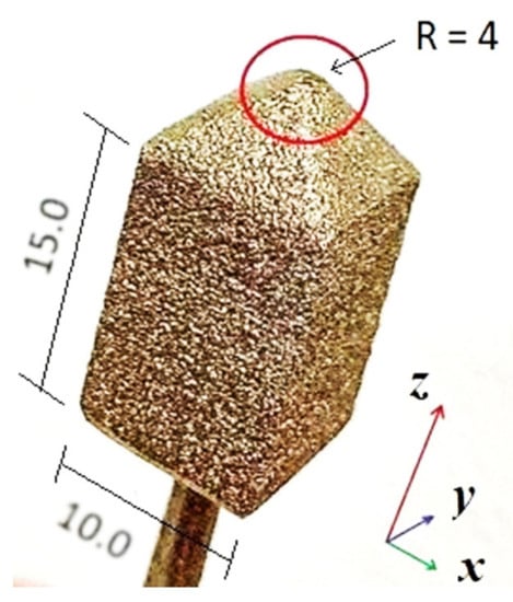
Figure 1.
Pin with round tip (sizes expressed in mm).
At room temperature, the pin microstructure is lamellar, a type of basket weave, with a greater vanadium content in the interlamellar zone, which consequently results in phase β, while the central zone of the lamellas is in phase α []. For metallography and results of the EDX analysis, see []. The hardness of the metallic pin is equal to 320 HV, much greater than that of the polymer. Therefore, it does not undergo significant wear phenomena during the pin-on-disc test.
The polymeric specimens were produced in the form of square sheets with 20 mm sides and 2 mm thickness, obtained by thermoforming the medical grade GUR1020-UHMWPE powder (average molecular weight of 2–4 × 10⁶ g/mol, density 0.93 g/cm3 without calcium stearate) provided by Celanese Corporation, Irving, TX, USA. The process parameters were set according to Suarez et al. []: temperature 200 °C and pressure increasing from 1 to 200 atm (1 min. at 0 bar, 1 min. at 50 bar, 1 min. at 100 bar, 1 min. at 150 bar, and 16 min. at 200 bar []). The plates surrounding the polymer mold for thermoforming were made of steel. The mold cavity has a size of 40 × 40 mm2, and a thickness of 2 mm, to obtain 4 specimens of size 20 × 20 mm2, with a thickness of 2 mm by simple manual cutting. To facilitate the release of the polymer from the mold, a sheet of Teflon® with a thickness of 0.1 mm was interposed both above and below the cavity.
2.2. Experimental Methods
After thermoforming, UHWMPE was characterized by thermal and mechanical tests; a differential scanning calorimetric (Q-100 DSC analyzer, supplied by TA Instruments, New Castle, DE, USA) and a Shore-D microhardness testing (PCE-DDD 10 analyzer, supplied by PCE Instruments, Meschede, Germany).
For DSC analysis, 6–8 mg specimens were prepared and heated from 25 °C to 200 °C at 10 °C min−1 under an inert atmosphere, according to ASTM DF2625 standard. DSC analysis provided the melting temperature (Tm) and enthalpy ΔHm of the samples. The crystallinity degree Xc was calculated by the following equation:
where ΔHm [J/g] is the melting enthalpy, ΔH0m is equal to 291 J/g and represents the hypothetical enthalpy of fusion of UHMWPE crystal of infinite extension, according to the literature [].
The surface hardness was measured according to the standard ASTM-2240 with shore-D scale and a 5 kg load. Six samples of UHMWPE were analyzed on their surface, and the final value was the average of ten measurements for each sample.
Wear tests were carried out at room temperature through a pin-on-disc device, both in dry and under lubrication with simulated synovial fluid (SSF) containing 0.3 wt % of Hyaluronic Acid (HA) in phosphate-buffered saline solution (pH 7.4). The inorganic electrolyte concentration in the SSF was: 153.1 mM of Na+, 4.2 mM of K+, 139.6 mM of Cl+, and 9.6 mM of phosphate buffer.
As shown in Figure 2, the pin was mounted with an offset r with respect to the rotation axis and loaded with 30 N. The rotating speed (n = 60 rpm) was constant in all the tests. A single specimen for each test was placed in a containment box fixed on the rotating disc and lubricated drop by drop. The working parameters were chosen in accordance with those commonly adopted by other authors [,,]. In particular, following a method developed in [] to simulate the real conditions in the hip joint, the load applied in the pin-on-disc test can be evaluated in the range of 20–30 N.
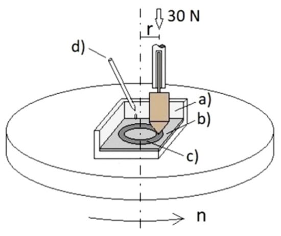
Figure 2.
Sketch of the pin-on-disc device: (a) section of the lubricant containment tray, (b) UHMWPE sheet, (c) wear track, (d) graduated pipette.
The tribometric trials were performed on different specimens at various times up to 240 min. Two different pins were utilized for the two series of tests (under lubrication with SSF and in dry conditions) for a total duration of each series equal to 525 min.
The metallic tip and the polymeric surface were observed using a digital microscope (Hirox KH-8700, Tokyo, Japan). Each polymeric specimen was examined using a confocal microscope (Leica DCM 3D, Leica Microsystems, Wetzlar, Germany). 3D images of grooves and plastic deformation accompanying the formation of wear tracks were obtained by an EPI 20X-L objective in LeicaScan DCM 3D software. To capture all points on the surface specimen, the z-scan covered a height of 224 μm, with z representing the orthogonal direction to the specimen surface. Post-processing of the images was performed using LeicaMap 6.2 software.
The scans were performed in slit confocal contrasting mode by illuminating the specimens with a high-power white LED (λ = 530 nm). The aperture of the objective was 0.5 in confocal mode, and the volume of the acquired image had the following sizes: 636.61 × 477.25 μm2 in the xy plane and 224 μm along the z-axis. The axial optical resolution (x, y directions) is rx = ry = 0.28 µm, and the vertical resolution (z-axis) is rz < 15 nm. Finally, the relative error referred to the acquisition volume is given by the sum of the relative errors [], resulting εr = 0.28/636.61 + 0.28/477.25 + 0.015/224 = 1.1 × 10⁻³.
3. Results
3.1. Polymeric Sheet Characterization
As is known, among the polymer characterization techniques, DSC calorimetry and Shore-D hardness represent effective analyzes for obtaining information on the structure of the macromolecule and the compactness of the material. The higher the degree of crystallinity, the better the physical–mechanical properties of the material. Each manufacturing process lowers these properties, and therefore, it is necessary to consider the possible structural variations that the process brings to the material itself.
The resulting melting temperature of UHMWPE studied in this work was 138.2 °C, the enthalpy was 142.45 J g−1, and consequently, the crystalline degree was 48.95%. The measured Shore D hardness resulted in 62.5 HD with a standard deviation equal to ±0.08 [,,]. These experimental data were compared in Table 2 with those of the UHMWPE-GUR 1020 data sheet of the material as supplied [].

Table 2.
Comparison between experimental data and UHMWPE-GUR 1020 datasheet.
It can be deduced that the transformation obtained by working with a hot press at a temperature of 200 °C and a pressure of 200 bars for 20 min slightly lowers the crystallinity (by 5.7%) and the surface hardness (by 5.1%) of the material. These results could be expected considering the effects of the manufacturing process, as stated in Section 3.1. Nonetheless, it does not significantly change the melting temperature, indicating good integrity of the plastic component.
3.2. Metallic Pin Contact Surface
Because the EBM process works with powder particles, the tip surface appears grainy and rough. In particular, the 3D image in Figure 3 was taken from the tip that worked for 525 min.
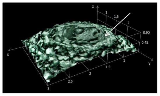
Figure 3.
3D image of the tip after 525 min in dry condition (the white arrow indicates a particle detachment zone).
It can be observed that the surface roughness of the tip affects the track formation on the UHMWPE sheets.
The optical observations of the metal tip show significant morphological changes after the completion of all wear treatments. For a qualitative evaluation of the wear effects, a zone inside a circle arbitrarily drawn around the pin vertex was considered (Figure 4 and Figure 5).
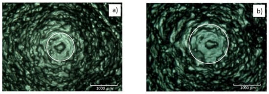
Figure 4.
Tip of the metallic pin: (a) before the tests, (b) after 525 min of trials lubricated with SSF [].
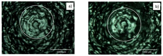
Figure 5.
Tip of the metallic pin: (a) before the tests, (b) after 525 min of trials in dry condition.
In Figure 4, the case of tests under lubrication with SSF is recalled from [] and compared with the observations after tests in a dry condition in Figure 5.
A redistribution of the metallic particles deposited during the EBM process occurs in the zones circumscribed by the white circle in Figure 4a,b. In fact, after 525 min in SSF, the same zone appears enclosed in a circle of greater diameter. It can be ascribed to an effect of local compression that causes a widening of the particle distribution after the tests in SSF.
Conversely, after 525 min in a dry condition, the widening of the particle distribution concerning the tip before tests is not observed, but a reduction of the particle number inside the white circle can be noted (Figure 5). Due to the higher hardness compared to that of the polymer, the metallic pin does not undergo significant wear phenomena. The authors interpreted the dark zone on the pin as a lack of metallic particles due to the limited effect of wear (debris not appreciable with a weight scale accuracy of 0.1 mg). The reduction of the number of particles inside the white circle with respect to the pin before the test can be ascribed to the friction forces typical of dry conditions, which have values five times higher than those acting under lubrication [].
The mass of Ti6Al4V debris can be deduced from the optical micrographs in Figure 5. Comparing the zones enclosed by the white circles, it can be noted that after 525 min in dry condition, about 20% of the area is depleted from metallic particles. Therefore, it results equal to 0.23 mm2. Assuming a mean value of 0.05 mm of the particle thickness, the debris volume results equal to 1.15 × 10⁻⁵ cm3, corresponding to a mass loss of Ti6Al4V equal to about 0.05 mg, less than the accuracy of the weight scale.
These relatively few pieces of metallic debris act as micro-cutting tools, giving rise to three-body wear by scratching the polymeric surface and producing many potentially dangerous particles for bioimplants []. This kind of debris is formed under abrasive wear when the asperities of a rough and hard surface slide against a softer counter-surface.
3.3. Polymeric Sheet Contact Surface
The UHMWPE specimens undergo progressive damage according to the wearing conditions, which determine the formation of grooves or tracks on their surface, as documented by the rendering in Figure 6, where three different specimens are compared.
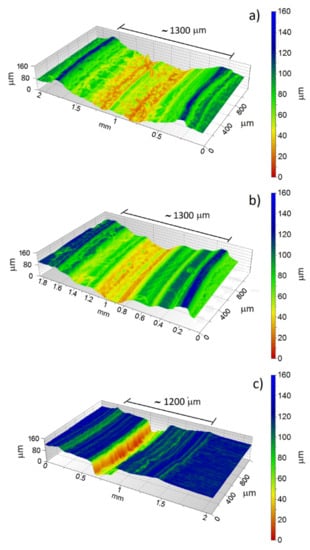
Figure 6.
Images obtained with the confocal microscope: (a) dry conditions after 60 min: (b) dry conditions after 240 min, (c) lubrication with SSF after 60 min.
The more severe dry conditions show the effects of the test time: an increment from 60 min (Figure 6a) to 240 min (Figure 6b) gives rise to a deeper groove. The radial width of the wear traces was measured by the confocal microscope, and the mean values were quite similar for the specimens tested for 60 and 240 min in dry conditions (about 1.3 mm). Instead, the wear track under lubrication is less wide (about 1.2 mm) than that obtained in dry conditions with the same test time (Figure 6c).
The increment of test time from 60 to 240 min in dry conditions gave rise to a higher amount of pile-up (due to the plastic flow of the material under contact with the metallic pin). In wet conditions, the groove was narrow, and the number of pile-ups was lower. However, compared to the respective groove volume, the presence of annular pile-ups is more accentuated after the test in SSF as a percentage (see the evaluation carried out in the Discussion).
In this regard, the Shore-D hardness measurements in the wear tracks [] showed a softening after wearing in SSF (the initial value is reduced by about 2 HD in the first 15 min and by only 3 HD in the interval from 15 to 240 min, due to a saturation effect). From this, it can be deduced that the fluid can increase the plasticity of the polymer surface.
This result agrees with the research by Visco et al. [], which shows how SFF smooths the surface of the material, spreading inside the polymer and decreasing its surface hardness. Diffusion is favored by rising temperatures. The friction of the metal tip punctually generates heat in the contact area, where the plasticizing effect is further favored.
The results of optical observations on the polymeric surface after the pin-on-disc trials are shown in Figure 7. The first two micrographs are characterized by several annular grooves with debris mainly inside them, as single particles or in clusters. Moreover, in the case of (b), scratches are present, probably due to the metal debris acting as micro-cutting tools. In the last micrograph, the number of grooves is lower, and polymeric material flows are visible.
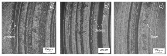
Figure 7.
Optical micrographs of the specimen surface: (a) dry condition after 60 min, (b) dry conditions after 240 min, (c) lubrication with SSF after 60 min.
The lubricating film is fundamental for reducing the asperities interaction between the surfaces in contact and improving wear behavior. In fact, the 3D images obtained with the confocal microscope (Figure 6) revealed that, in dry conditions, the height of the pile-ups is higher than under lubrication. Moreover, in SSF, the wear track is narrower than in dry conditions. Finally, in the case of lubrication, the reduced presence of debris (Figure 7c) demonstrates a prevalence of adhesive mechanisms.
The adhesive wear mechanism arises if the strength of the bonds at the contact between the metallic and the polymeric surface exceeds the cohesion of the softer material []. In this case, a flow of the softer material occurs. An adhered layer is formed, as shown in Figure 7, and documented by various authors for tribocouples of materials characterized by a high difference in hardness values [,].
4. Discussion
To evaluate the polymeric debris volume and the percentage of material subject to plastic deformation, the circular wear track and the corresponding section along the radial direction were considered for each specimen. The adopted procedure starts from the polymeric sheet after the wear test (Figure 8a); a radial section is individuated, as shown in Figure 8b, obtaining the wear groove profile in Figure 8c.

Figure 8.
Procedure for tracing the wear grove profile: (a) UHMWPE sheet with circular wear track and indication of the mean diameter (Φ), (b) radial section of the wear track, (c) wear profile.
The wear profiles are characterized by grooves with respect to the reference line corresponding to the sheet surface, whose depth is affected by the test conditions (Figure 9). Moreover, the lateral pile-ups due to the plastic flow of the polymer are evident.
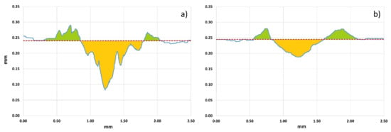
Figure 9.
Example of wear profiles obtained after trials lasting 180 min: (a) dry conditions, (b) lubrication with SSF.
It can be assumed that the material that leaves the empty area (yellow area) of the groove below the reference dashed red line partly contributes to the formation of debris and partly to the lateral corrugations (green areas). Therefore, the volume of debris can be obtained by multiplying the difference between the yellow area (A(yellow)) and the green area (A(green)) by the length of the mean circumference (corresponding to the diameter indicated in Figure 8a).
Four different sections (i = 1–4) were considered for each specimen. Therefore, the volume of debris (Vdebris) and the volume of material contributing to plastic deformation (Vplastic) are obtained by applying the following relationships:
The absolute error (εa) of the volumetric measurements can be calculated as follows:
Figure 9 shows that the ratio of Vplastic/Vdebris is significantly higher in SSF than in dry conditions (1.32 in the former case, 0.42 in the latter). It can be ascribed to the plasticizing effect of the hyaluronic acid present in SSF, which lowers the wearing effects of the metallic tip on the polymer surface.
The volume of debris Vdebris (mm3) is usefully reported vs. the sliding length L (m) during each wear test:
being r (m) the radius of the circular track that the metallic tip leaves on the polymeric surface after the duration t (min) of a single trial.
These curves are characterized by an initial transient stage in which the Vdebris rates reduce progressively until a stationary linear stage is reached []. This was also documented in the literature by [] for the same tribological couple under the higher relative speed.
The specific wear rate Ws (mm3/Nm) can be calculated as the slope of the linear stage (dVdebris/dL) divided by the applied load (P = 30 N):
In Figure 10a, the experimental points of volume loss, obtained with weight measurements, are shown; in Figure 10b, the curve Vdebris vs. L that interpolates the experimental data obtained with direct volume measurements is compared with that deduced from weight measurements. Some considerations can be drawn as follows.
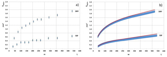
Figure 10.
Debris volume vs. slight length in dry conditions and in SSF: (a) experimental points of Vdebris vs. L deduced from weight measurements [], (b) Comparison between curves deduced from weight measurements (blue ribbons) and curves obtained with volume measurements (red lines).
First, a positive consequence of direct volumetric measurements is their better accuracy. In fact, considering the relative volumetric error εr = 1.1 × 10⁻³, the absolute one varies from about 0.7 × 10⁻³ to 2.1 × 10⁻³ mm3 in dry conditions and from about 0.2 × 10⁻³ to 0.8 × 10⁻³ mm3 in SSF. Therefore, the respective diagrams are represented by red lines drawn with thin thicknesses. Instead, carrying out weight measurements with an absolute constant error of 10−4 g and being the UHMWPE density equal to 9.355 × 10⁻⁴ g/mm3, the resulting absolute volumetric error is constant and equal to about 0.1 mm3. It leads to wider margins of errors for these diagrams, which are consequently represented by blue ribbons.
It can be observed that in dry conditions, the debris volume is higher due to the formation of deeper wear tracks on the polymer sheets. Furthermore, all curves drawn from volumetric measurements are slightly shifted with respect to those obtained from weight measurements []. It can be explained as an effect of the absorption of humidity that enhances the specimen weight after the test. Therefore, the debris weight, obtained by subtraction from the initial specimen weight, has underestimated results. This effect is more evident at the increase of the test time; consequently, the specific wear rate values, proportional to the slope of the linear stage, tend to be slightly higher for curves obtained with volumetric measurements than those for curves deduced from weight measurements. This is confirmed by comparison with the values of Ws obtained by the curve interpolating the weight measurements in Figure 10a and reported in Table 3. In the same table, the data in brackets highlight the uncertainty in the assessment by weight measurements since they are the maximum values of Ws that can be estimated considering the entire range of errors (blue ribbons in Figure 10b). In comparison, the uncertainty of the values of Ws obtained with volume measurement results is negligible.

Table 3.
Specific wear rates obtained with weight (a) and volume measurements (b).
5. Conclusions
The wear behavior between a Ti6Al4V pin and a UHMWPE rotating sheet was investigated through morphological observations of the surfaces in contact, highlighting the detachment of material particles and the beneficial effects of lubrication in reducing debris production.
A method for direct measurements of volume loss performed by optical microscopy observations was proposed. Even though the absolute error increases with the test time, for the duration usually considered, this procedure is characterized by a greater degree of concordance between the value of the measured quantity and the real one with respect to that intrinsic to weight measurements. Furthermore, volume measurements allow for avoiding any possibility of error in weighing the polymeric specimens, which could have absorbed humidity during the wear tests.
The behavior of the debris volume according to the sliding length is characterized by an initial transient stage until a stationary linear stage is reached. Our investigations confirmed the positive effect of lubrication in simulated synovial fluid, which significantly reduces polymer wear compared to dry conditions. Moreover, the morphology of the wear track was characterized through evaluating the rates of material that, in part, is detached in the form of flow or debris, leaving a wear track on the polymer surface, and in part contributes to the formation of plastic pile-ups.
As for the metallic pin, the volumetric measurements showed the formation of a mass of debris lower than the accuracy of the weight scale, but it could be potentially dangerous to the prosthetic joints in the long run and deserves to be further explored.
Author Contributions
Conceptualization, A.V. and A.S.; methodology, A.V., G.E., F.G., C.S. and A.S.; validation, A.V., G.E., F.G., C.S. and A.S.; formal analysis, A.V., G.E., F.G., C.S. and A.S.; investigation, A.V., G.E., F.G., C.S. and A.S.; resources, A.V.; data curation, A.V., G.E., F.G., C.S. and A.S.; writing—original draft preparation, F.G. and A.S.; writing—review and editing, A.V., G.E., F.G., C.S. and A.S.; visualization, A.V., G.E., F.G., C.S. and A.S.; supervision A.V. and A.S. All authors have read and agreed to the published version of the manuscript.
Funding
This research received no external funding.
Institutional Review Board Statement
Not applicable.
Informed Consent Statement
Not applicable.
Data Availability Statement
The data presented in this study are available on request from the corresponding author.
Conflicts of Interest
The authors declare no conflict of interest.
References
- Breme, H.; Biehl, V.; Reger, N.; Gawalt, E. Metallic biomaterials: Introduction. In Handbook of Biomaterial Properties; Murphy, W., Black, J., Hastings, G., Eds.; Springer: New York, NY, USA, 2016; pp. 151–158. [Google Scholar]
- Merola, M.; Affatato, S. Materials for hip prostheses: A review of wear and loading considerations. Materials 2019, 12, 495. [Google Scholar] [CrossRef] [PubMed]
- Tamayo, J.A.; Riascos, M.; Vargas, C.A.; Baena, L.M. Additive manufacturing of Ti6Al4V alloy via electron beam melting for the development of implants for the biomedical industry. Heliyon 2021, 7, e06892. [Google Scholar] [CrossRef] [PubMed]
- Cronskär, M.; Bäckström, M.; Rännar, L. Production of customized hip stem prostheses—A comparison between conventional machining and electron beam melting (EBM). Rapid Prototyp. J. 2013, 19, 365–372. [Google Scholar] [CrossRef]
- Yousef, S.; Visco, A.M.; Galtieri, G.; Njuguna, J. Wear characterizations of polyoxymethylene (POM) reinforced with carbon nanotubes (POM/CNTs) using the paraffin oil dispersion technique. JOM 2016, 68, 288–299. [Google Scholar] [CrossRef]
- Surya, M.S.; Prasanthi, G.; Kumar, A.K.; Sridhar, V.K.; Gugulothu, S.K. Optimization of cutting parameters while turning Ti-6Al-4 V using response surface methodology and machine learning technique. Int. J. Interact. Des. Manuf. 2021, 15, 453–462. [Google Scholar] [CrossRef]
- Ahmed, N.; Abdo, B.M.; Darwish, S.; Moiduddin, K.; Pervaiz, S.; Alahmari, A.M.; Naveed, M. Electron beam melting of titanium alloy and surface finish improvement through rotary ultrasonic machining. Int. J. Adv. Manuf. Technol. 2017, 92, 3349–3361. [Google Scholar] [CrossRef]
- Aliprandi, P.; Giudice, F.; Guglielmino, E.; Sili, A. Tensile and creep properties improvement of Ti-6Al-4V alloy specimens produced by Electron Beam Powder Bed Fusion Additive Manufacturing. Metals 2019, 9, 1207. [Google Scholar] [CrossRef]
- Patil, N.A.; Njuguna, J.; Kandasubramanian, B. UHMWPE for biomedical applications: Performance and functionalization. Eur. Polym. J. 2020, 125, 109529. [Google Scholar] [CrossRef]
- Macuvele, D.L.P.; Nones, J.; Matsinhe, J.V.; Lima, M.M.; Soares, C.; Fiori, M.A.; Riella, H.G. Advances in ultra high molecular weight polyethylene/hydroxyapatite composites for biomedical applications: A brief review. Mater. Sci. Eng. C 2017, 76, 1248–1262. [Google Scholar] [CrossRef]
- Catauro, M.; Scolaro, C.; Dal Poggetto, G.; Pacifico, S.; Visco, A. wear resistant nanocomposites based on biomedical grade UHMWPE paraffin oil and carbon nano-filler: Preliminary biocompatibility and antibacterial activity investigation. Polymers 2020, 12, 978. [Google Scholar] [CrossRef]
- Visco, A.; Grasso, A.; Recca, G.; Carbone, D.C.; Pistone, A. Mechanical, wear and thermal behavior of polyethylene blended with graphite treated in ball milling. Polymers 2021, 13, 975. [Google Scholar] [CrossRef]
- Dong, H.; Shi, W.; Bell, T. Potential of improving tribological performance of UHMWPE by engineering the Ti6Al4V counterfaces. Wear 1999, 225–229, 146–153. [Google Scholar] [CrossRef]
- Visco, A.; Grasso, A.; Scolaro, C.; Belhamdi, H.; Sili, A. Tribological behavior of UHMWPE (disc) against Ti6Al4V (pin) under different lubrication conditions. Macromol. Symp. 2022, 404, 2100294. [Google Scholar] [CrossRef]
- Belhamdi, H.; Kouini, B.; Grasso, A.; Scolaro, C.; Sili, A.; Visco, A. Tribological behavior of biomedical grade UHMWPE with graphite-based fillers against EBM-Ti6Al4V pin under various lubricating conditions. J. Appl. Polym. Sci. 2022, 139, 52313. [Google Scholar] [CrossRef]
- Barber, H.; Kelly, C.N.; Abar, B.; Allen, N.; Adams, S.B.; Gall, K. Rotational wear and friction of Ti-6Al-4V and CoCrMo against polyethylene and polycarbonate urethane. Biotribology 2021, 26, 100167. [Google Scholar] [CrossRef]
- Zhang, X.; Chen, K.; Xu, L.; Qi, J.; Luo, Y.; Zhang, D. Tribological behavior of Ti6Al4 V alloy swing against UHMWPE under different lubrication. J. Thermoplast. Compos. Mater. 2022, 35, 740–757. [Google Scholar] [CrossRef]
- Tai, Z.; Chen, Y.; An, Y.; Yan, X.; Xue, Q. Tribological behavior of UHMWPE reinforced with graphene oxide nanosheets. Tribol. Lett. 2012, 46, 55–63. [Google Scholar] [CrossRef]
- Guezmil, M.; Bensalah, W.; Mezlini, S. Tribological behavior of UHMWPE against TiAl6V4 and CoCr28Mo alloys under dry and lubricated conditions. J. Mech. Behav. Biomed. Mater. 2016, 63, 375–385. [Google Scholar] [CrossRef]
- Visco, A.; Giudice, F.; Guglielmino, E.; Scolaro, C.; Sili, A. Experimental investigation of the tribological contact between Ti6Al4V-EBM pin and UHMWPE rotating sheet for prosthetic applications. Metals 2022, 12, 1526. [Google Scholar] [CrossRef]
- Yang, L. Wear coefficient equation for aluminium-based matrix composites against steel disc. Wear 2003, 255, 579–592. [Google Scholar] [CrossRef]
- Qu, J.; Blau, P.J.; Watkins, T.R.; Cavin, O.B.; Kulkarni, N.S. Friction and wear of titanium alloys sliding against metal, polymer, and ceramic counterfaces. Wear 2005, 258, 1348–1356. [Google Scholar] [CrossRef]
- Shen, G.; Zhang, J.-F.; Fang, F.-Z. In vitro evaluation of artificial joints: A comprehensive review. Adv. Manuf. 2019, 7, 1–14. [Google Scholar] [CrossRef]
- Galati, M.; Iuliano, L. A literature review of powder-based electron beam melting focusing on numerical simulations. Addit. Manuf. 2018, 19, 1–20. [Google Scholar] [CrossRef]
- Harun, W.S.W.; Manam, N.S.; Kamariah, M.S.I.N.; Sharif, S.; Zulkifly, A.H.; Ahmad, I.; Miura, H. A review of powdered additive manufacturing techniques for Ti-6al-4v biomedical applications. Powder Technol. 2018, 331, 74–97. [Google Scholar] [CrossRef]
- Acquesta, A.; Monetta, T. As-built EBM and DMLS Ti-6Al-4V parts: Topography–corrosion resistance relationship in a simulated body fluid. Metals 2020, 10, 1015. [Google Scholar] [CrossRef]
- Miguez Suarez, J.C.; de Biasi, R.S. Effect of gamma irradiation on the ductile-to-brittle transition in ultra-high molecular weight polyethylene. Polym. Degrad. Stab. 2003, 82, 221–227. [Google Scholar] [CrossRef]
- Visco, A.; Yousef, S.; Galtieri, G.; Nocita, D.; Pistone, A.; Njuguna, J. Thermal, Mechanical and rheological behaviors of nanocomposites based on UHMWPE/Paraffin oil/Carbon nanofiller obtained by using different dispersion techniques. JOM 2016, 68, 1078–1089. [Google Scholar] [CrossRef]
- Souza, V.C.; Oliveira, J.E.; Lima, S.J.G.; Silva, L.B. Influence of vitamin C on morphological and thermal behaviour of biomedical UHMWPE. Macromol. Symp. 2014, 344, 8–13. [Google Scholar] [CrossRef]
- Mohammadhosseini, A.; Fraser, D.; Masood, S.H.; Jahedi, M. Investigation of wear properties of EBM processed Ti6Al4V with UHMWPE for biomedical applications. Appl. Mech. Mater. 2015, 811, 14–18. [Google Scholar] [CrossRef]
- Boampong, D.K.; Green, S.M.; Unsworth, A. N+ ion implantation of Ti6Al4V alloy and UHMWPE for total joint replacement application. J. App. Biomater. Func. 2003, 1, 164–171. [Google Scholar] [CrossRef]
- Borruto, A. A new material for hip prosthesis without considerable debris release. Med. Eng. Phys. 2010, 32, 908–9131. [Google Scholar] [CrossRef]
- Taylor, J.R. An Introduction To Error Analysis. The Study of Uncertainties in Physical Measurements, 2nd ed.; University Science Books: Sausalito, CA, USA, 1997; ISBN 0935702423. [Google Scholar]
- Campo, N.; Visco, A.M. Properties of nanocomposites based on polyethylene (UHMWPE) and carbon nanotubes mixed by high-energy ball milling and UV-source irradiated. Int. J. Polym. Anal. Charact. 2012, 17, 144–157. [Google Scholar] [CrossRef]
- Visco, A.M.; Brancato, V.; Torrisi, L.; Cutroneo, M. Employment of carbon nanomaterials for welding polyethylene joints with a Nd:YAG laser. Int. J. Polym. Anal. Charact. 2014, 19, 489–499. [Google Scholar] [CrossRef]
- Visco, A.M.; Torrisi, L.; Campo, N.; Picciotto, A. Comparison of surface modifications induced by ion implantation in UHMWPE. Int. J. Polym. Anal. Charact. 2010, 15, 73–86. [Google Scholar] [CrossRef]
- Extrulen 1020-Product Data Sheet. Available online: https://media.mcam.com/fileadmin/quadrant/documents/QEPP/EU/Product_Data_Sheets_PDF/Medical/MCAM-MEDI-403-A2-Extrulen-1020-EN-PDS-200506.pdf (accessed on 6 March 2023).
- Shen, G.; Fang, F.; Kang, C. Tribological performance of bioimplants: A comprehensive review. Nanotechnol. Precis. Eng. 2018, 1, 107–122. [Google Scholar] [CrossRef]
- Visco, A.; Richaud, E.; Scolaro, C. Ageing of UHMWPE in presence of simulated synovial fluid. Polym. Degrad. Stab. 2021, 189, 109605. [Google Scholar] [CrossRef]
- Myshkin, N.; Kovalev, A. Adhesion and friction of polymers and polymer composites. In Handbook of Polymer Tribology; Sinha, S.K., Ed.; World Scientific: Singapore, 2018; pp. 3–45. [Google Scholar]
- Saravanan, I.; Elaya Perumal, A.; Balasubramanian, V. A study of frictional wear behavior of Ti6Al4V and UHMWPE hybrid composite on TiN surface for bio-medical applications. Tribol. Int. 2016, 98, 179–189. [Google Scholar] [CrossRef]
- Salguero, J.; Vazquez-Martinez, J.; Sol, I.; Batista, M. Application of pin-on-disc techniques for the study of tribological interferences in the dry machining of A92024-T3 (Al–Cu) alloys. Materials 2018, 11, 1236. [Google Scholar] [CrossRef]
Disclaimer/Publisher’s Note: The statements, opinions and data contained in all publications are solely those of the individual author(s) and contributor(s) and not of MDPI and/or the editor(s). MDPI and/or the editor(s) disclaim responsibility for any injury to people or property resulting from any ideas, methods, instructions or products referred to in the content. |
© 2023 by the authors. Licensee MDPI, Basel, Switzerland. This article is an open access article distributed under the terms and conditions of the Creative Commons Attribution (CC BY) license (https://creativecommons.org/licenses/by/4.0/).