Abstract
This work proposes an Internet-of-Things (IoT) device for remote elevator control. The new contribution of this proposal to the state-of-the-art is that it can convert a manually operated elevator into a remote controlled elevator without requiring any intrusive manipulation or wiring connection in the elevator. This IoT device has been designed as an add-on non-contact tool which is placed over the original elevator button panel, using servomotors to press the original buttons. This design allows its fast deployment as a remote control tool that increases elevator accessibility through the use of messages, a webpage or a QR code. Some application examples of this proposal are non-contact use of elevators in pandemic conditions, and the unsupervised use of elevators by autonomous cleaning or delivery mobile robots. The experimental evaluation of the IoT device in real operational conditions has validated its non-contact control features.
1. Introduction
An elevator or lift is a machine that vertically transports people or goods between different floors. The elevator is an infrastructure commonly present in multistory buildings that is designed to be used intensively by multiple users in quick succession. The most common method used to control an elevator is via its button panel, which is prone to cause some problems: the shared use of tactile buttons may contribute to the spread of infectious diseases in pandemic conditions; the button panel can be hard to use by people with severe physical disabilities; and the location and use of a button panel is a challenging perception and control problem that also limits the unsupervised use of autonomous mobile robots in multistory buildings. In general, the scientific literature has highlighted the accessibility problems of built environments [1] and the need to enhance social equity by enabling the access, inclusion, and participation of people [2] and children [3] with disabilities.
New Contribution
This paper tackles the aforementioned problems by proposing the design and implementation of a non-contact and non-intrusive add-on wireless Internet-of-Things (IoT) device for remote elevator control. This tool has been designed as an external button panel attached above the original elevator car buttons. The physical action of pressing the buttons of the panel is performed by a set of low-cost servomotors, and the device is remotely accessed through the wireless network of the building. The IoT device has been designed as a battery-operated non-intrusive equipment in order to avoid any manipulation or additional wiring connection that may compromise any security standard or regulation. The design of the IoT device allows direct machine-to-machine (M2M) interaction through an Internet-based communication protocol. The internal structure of this IoT device has been designed to ensure its compatibility with the stock button panel, which must remain usable in case the battery runs out. This was achieved by including pressure-sensitive buttons that transfer the pressure to the original button panel of the elevator. The device specifically avoids the shared use of buttons by providing a smartphone-based web interface to control the elevator. This web interface can be accessed from a visual quick response (QR) code that simplifies access to the web interface of the elevator and reduces the number of actions that need to be performed by the user to call the elevator, which is called automatically after scanning the QR code.
This contribution was inspired by the proposals of Bo et al. [4] and Lai et al. [5], who developed several devices with a similar objective, and by the conclusion of Pearson et al. [6], who recommended the use of add-on devices for elevator control. However, until now, the devices proposed for remote elevator control required intrusive manipulation of the original infrastructure [4,5,7]. This is a strong limitation because intrusive intervention in elevators may not be feasible in most cases because of its cost, the closed design of the elevator, and the particularities of strict regulations regarding elevators.
The IoT device has been deployed in a real elevator and has been experimentally tested by users accessing the elevator with their smartphones and by an autonomous mobile robot.
2. Related Work
The Internet-of-Things (IoT) enables the inclusion of sensors, actuators and software in physical objects such as lights, windows, doors and home appliances, which are able to share data through the Internet. In the case of elevators, the application of IoT has mostly focused on monitoring [8,9]. Currently, however, the IoT is being used in several fields, such as garbage waste management [10], intrusion detection [11,12], parcel classification [13], greenhouse monitoring [14,15], development of smart cities [16], and indoor quality monitoring [17], among others. The IoT device proposed in this paper provides elevator control from smartphones, as well as quick, non-contact access to the control interface via QR codes. This control method can also be used by mobile robots in a direct, machine-to-machine communication.
2.1. Elevator Implementation and Optimization
In order to guarantee the safety of their users, elevators must comply with a set of strict regulations that are taken into consideration during their design, manufacturing, installation, and maintenance process. The technological advances that elevators represent in tall multistory buildings were summarized by Al-Kodmany [18]. The specific scientific literature regarding elevators is usually focused on power consumption and energy-saving strategies [19,20,21]; traffic patterns analysis and optimization [22,23]; system performance analysis [24,25]; hardware and control system improvement [26,27]; operation analysis [28,29]; failure analysis [30,31]; analysis and reduction of noise and vibrations [32,33]; inspection and maintenance tasks [34,35]; emergency evacuation procedures [36,37]; and energy consumption evaluation and modelling [38].
2.2. Non-Contact Elevator Control
The use of non-contact technologies for elevator control has been analyzed in the scientific literature. Pearson et al. [6] investigated the integration of touchless technology in public infrastructures in order to remove the need of touching the buttons of control panels located in public or shared spaces. One of their recommendations was the use of an add-on console device equipped with a proximity sensor to allow people to call the elevator by placing their hand in front of it. Similarly, Kane et al. [39] conducted an online survey with 40 adults with different physical disabilities about their experiences with sensing systems. They presented the challenges they faced when interacting with motion sensors, biometric sensors, speech input, and touch and gestures systems. Some of the problems reported were the challenges that represent the visual or sensory identification of a button panel, the reach of the console button panel, and the application of the correct amount of pressure when interacting with its buttons.
In this direction, the development of Internet-of-Things devices is an emerging field with potential to improve the quality of life of people with disabilities [40]. Another common proposal to achieve non-contact control of elevators is the use of speech-recognition based alternatives. For example, Yulianto et al. [41] presented a non-contact proposal for elevator control based on speech recognition. Liu et al. [42] proposed a contactless, voice-activated elevator-control panel combined with the use of electromagnetic switches attached to the original elevator button panel. Similarly, Shinde et al. [43] proposed a contactless CNN-based single-command speech recognition system to control elevators using the voice with the aim of reducing the challenge that elevators represent for people with disabilities. Meenatchi et al. [44] presented a voice recognizing system for people with paraplegia and visual impairments. However, the use of an elevator by people with severe physical disabilities may require the development of specialized interfaces. Chatziparasidis et al. [45] presented a brain-computer interface (BCI) solution for elevator control. Their prototype uses brain signals to provide means of communication between users and elevators. They demonstrated that elevators with BCI functionalities [46] can be affordable and are feasible from a practical point of view. Extended information on BCI can be found in the review presented by Nicolas-Alonso et al. [46].
One of the common limitations of the above-mentioned reference works is that their implementation may require some degree of intrusive manipulation of the structure or electrical wiring of the elevator. This limitation has been addressed in this work by proposing an optimized, battery-operated IoT device for remote elevator control that does not require any kind of structural or electrical manipulation of the original elevator. This implementation has potential to allow the rapid deployment of specific functionalities to assist people with disabilities in the use of elevators.
2.3. Elevator Panel Buttons and COVID-19 Pandemic
The coronavirus disease 2019 (COVID-19) pandemic highlighted the need to reevaluate the way people interact with shared objects such as door handles, button panels, and handrails in order to reduce the contagion risk of infectious diseases. During the outbreak of the pandemic, people were aware of the risks of coming into contact with shared objects, and the importance of maintaining adequate hand hygiene as prevention measures to avoid infection. This may be one of the causes of the low COVID-19 infection rates attributed to contact with fomites reported in the scientific literature [47,48]. However, Wu et al. [49] measured the environmental contamination of SARS-CoV-2 in a hospital in order to assess the role it may have in the transmission of the virus, reporting that the surface of the elevator buttons were positively contaminated with SARS-CoV-2 in 42.86% of the case samples analyzed. These findings confirm the need to consider the physical contact with shared button panels as a path for pathogen transmission.
In the context of the COVID-19 pandemic, the concept of the Internet-of-Things has fostered the development of new multi-sensor devices [50,51]. Some alternatives designed to specifically mitigate the risk of infection in elevators are the deployment of automatic disinfection systems using UV-C light [52] and the implementation of contact-free buttons [53]. Alternatively, Bo et al. [4] designed an epidemic prevention and protection plan to be followed when using an elevator, along with the proposal of a contact-free elevator device that allows interacting with the elevator through hand gestures or by using a mobile phone app. Once the user has entered the elevator car, the destination can be selected using smart cards, QR codes, voice, infrared induction buttons, or face recognition. Similarly, Lai et al. [5] explored the control mechanisms for developing a contact-free elevator-ride system based on a combination of speech recognition, contact-free perceptual buttons, gesture-recognition sensors, an app, and a web page browser.
The use of a web application and QR codes proposed by the cited works were the inspiration for the implementation of the add-on IoT device proposed in this paper. In this case, the development of a non-intrusive add-on device is proposed as a quick response tool to fight against pathogen transmission in places were the modification of touch-based elevator-control panels has not been considered, either due to its cost or its practical availability.
3. Materials and Methods
The main materials used in this paper are an ordinary elevator, in which the proposed device is attached; the servomotors used to mechanically push the original buttons of the elevator; an ESP-32 controller module that controls the servomotors and provides wireless remote elevator control; and a lithium-ion battery. The main method used to develop the proposal is additive manufacturing (3D printing).
3.1. Elevator
The elevator used in this paper to experimentally evaluate the performance of the IoT device belongs to the Polytechnic School of the University of Lleida. This facility is a five-story structure, including one basement, one ground floor and three upper floors. The elevator system has two independent cars. Each one has call buttons outside and two redundant button panels inside; one located at 1.1 m from the ground and the other at 0.7 m. There is an additional emergency panel to establish communication with the concierge in case of emergency, and two handrails, one at each side of the car.
Figure 1a shows the original button panels of the elevator and Figure 1b the detail of the lower button panel. The proposed IoT device is designed to mechanically activate the buttons on the lower panel of the elevator (Figure 1b). For this, a microcontroller circuit operates a set of servomotors that directly press the buttons. In the case of this application, the IoT device is non-invasively hung on the handrail in order to cover the lower button panel of the elevator; a suction cup located below the casing ensures that the structure is properly attached to the wall to provide additional leverage to the servomotors. The proposal is defined as non-invasive because it does not require mechanical or electrical manipulation of the elevator.
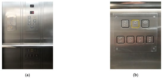
Figure 1.
Button panels of the elevator: (a) detail of the upper, lower and emergency panels; (b) detail of the lower panel that will be covered by the IoT add-on device.
3.2. Servomotors as Actuators
The IoT add-on device includes 7 low-cost servomotors to push the 7 buttons of the elevator panel (Figure 1b), one servomotor per button. The servomotors used are the Futaba S3003 model, which have a rotation range of 180° and can be operated at 5 V. These analog servomotors are able to provide up to 3.2 kg·cm of output torque, which is over ten times the torque required to push the buttons of the elevator panel. The advantage of this standard servomotor is its reduced size (39.9 × 20 × 36.1 mm), a feature that is required to pack several servomotors together and create a compact device. The target position of the servomotor shaft is established by a digital Pulse-Width Modulation (PWM) signal with a frequency of 50 Hz. The output angle of the shaft is proportional to the pulse width of the PWM signal; changing linearly between 0° (pulse width of 0.5 ms) and 180° (pulse width of 2 ms).
3.3. ESP32-S2-WROVER
The IoT device is based on an ESP32-S2-WROVER module developed by Espressif Systems (Shenzhen, China). This module has an ESP32-S2 microcontroller that includes an Xtensa LX7 32-bit microprocessor running at 240 MHz; 16 MB of usable flash memory for storing software and data; 320 kB of internal SRAM; and 37 general purpose input/output pins. The ESP32-S2 microcontroller also embeds an onboard antenna that supports a 2.4 GHz WiFi connection over the 802.11 b/g/n protocols. The WiFi connection is used to link the device to a wireless network. Additionally, the microcontroller includes standard peripheral modules, such as UART, SPI, I2C, and I2S communication modules, PWM and pulse signal units, an ADC, a DAC and a temperature sensor. Finally, this control module also supports a full-speed USB 2.0 on-the-go (OTG) connection.
3.4. Battery
The IoT device has been designed to be powered through a 5 V Li-ion battery pack with a capacity of 20,000 mAh and a total of 100 Wh of stored energy, which is expected to be enough to provide autonomy for up to seven days depending on the servomotor use.
4. Design and Implementation of the IoT Device
The following subsections describe the design and implementation of the IoT device proposed for elevator control. The casing of the device is a parallelepiped that holds all the elements of the system and covers the button panel. The casing does not include a back panel to allow direct contact between the servomotors and the elevator buttons.
4.1. Mechanical Activation of the Buttons
The mechanical activation of the original buttons of the elevator’s control panel is achieved with servomotors. Figure 2a shows a servomotor in inactive state, with the arm parallel to the button panel. Figure 2b shows a servomotor in active state, in which the arm rotates to press the original button of the control panel. The effective pressure performed by the servomotor, the angle of the arm, and its relative height over the original button panel, must be adapted to the button panel available in each application case.
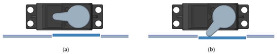
Figure 2.
Push button activation with servomotors: (a) button (blue part) released; (b) button (blue part) pressed.
4.2. Compatibility with the Original Button Panel
The IoT device has been designed to be compatible with manual operation of the buttons that compose the original button panel, a feature that is especially required for an add-on device in case the internal battery runs out of power. Figure 3 shows an illustrative representation of the system proposed to replicate the behavior of the original buttons of the elevator’s control panel. The front side of the casing (Figure 3a) includes an additional set of buttons with a pressure sensitive area that transmits any pressure to the original buttons underneath. Figure 3a shows a front view of one of the additional buttons, which are similar to a flexible cantilever. When pressed (Figure 3c), the area that joins the cantilever to the casing is elastically deformed, transferring the pressure to the original buttons through a column attached to the cantilever.
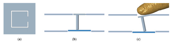
Figure 3.
Design of the additional buttons in the casing compatible with the manual operation of the original button panel: (a) front view of a cantilever-like button; (b) top view of the cantilever-like button and of the original button (blue part); (c) top view representation of the effect of a finger pressing one of the additional buttons.
4.3. IoT Device: Mechanical Design
Figure 4 shows a CAD representation of the planned disposition of the servomotors, battery, and control module placed in front of the elevator button panel. The distribution of the servomotors has been adapted specifically to match the original button panel. In this case, there is enough space to allocate the battery and the control system in the middle of the IoT device.
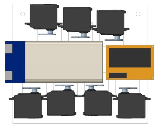
Figure 4.
Distribution of the servomotors, battery, and control module.
The complete mechanical implementation of the IoT device is based on 3D printing. Figure 5 shows a rear view of the IoT device. The servomotors and the battery are held by belts screwed into the casing. A set of ribs provide strength to the case structure, while two thin guiding walls are used to fit the casing relative to the protruding button panel, fixing the casing in its correct position. The case was printed with PolyLactic Acid (PLA) HR-870, which provides enhanced mechanical and thermic properties compared to standard PLA. The printing procedure lasted 19 h 27 min and used approximately 11.75 g of filament material.
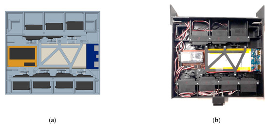
Figure 5.
Back view of the IoT device: (a) CAD representation; (b) real implementation.
Figure 6 shows the planned and real placement of the IoT device over the elevator button panel. In this application case, the placement of the casing in front of the elevator button panel is achieved by sliding the device between the elevator wall and the handrail until the two top flaps of the case rest over it, fitting the guiding walls around the button panel and then fixing its position with the suction cup located on its lower part. In cases where the handrail cannot be used to fix the IoT device over the original button panel, additional suction cups may be used in order to secure it in the right position.
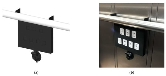
Figure 6.
Application of the IoT device as an add-on module: (a) CAD representation; (b) real implementation with labels over the cantilever-like buttons that replicate the original control panel.
Figure 7 shows a detail of the labels placed over the cantilever-like buttons that replicate the original control panel. Each label or button cover includes a symbol (open doors, emergency bell) or a printed number (from −1 to 3) representing one floor, each with its corresponding Braille description. The size and position of the Braille text within the sticker has been defined in accordance with standard recommendations [54,55]. The Braille texts referring to the emergency bell and the door aperture are written in Catalan language. The Braille abbreviation of the words that describe symbols are: “ala”, which stands for “alarma” (alarm, noun), and “obr”, which stands for “obrir” (open, verb). The profile of the Braille dots was generated with a pressure tool.
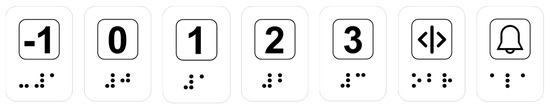
Figure 7.
Design of the plastic cover attached over the cantilever-like buttons of the IoT device.
4.4. IoT Device: Electronic Design
Figure 8 shows a schematic representation of the electronic design implemented in the IoT device. The system is based on an ESP32-S2 WROVER control module mounted on an ESP32-S2-Saola development board, which is a standard configuration for rapid electronic prototyping. The ensemble is mounted on an adapter board (Figure 8, brown rectangle) which provides connectivity with the battery and the analog servomotors.
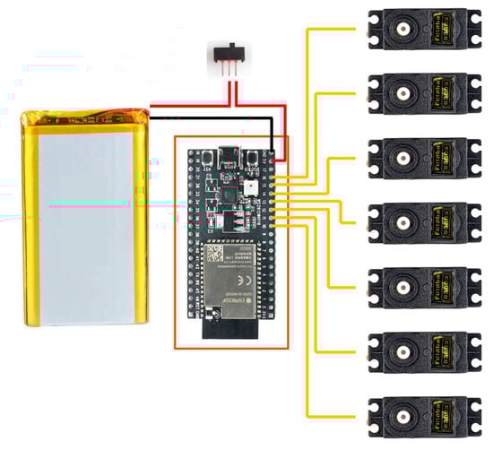
Figure 8.
Schematic representation of the electronic design.
4.5. IoT: Web Interface
The control module has been configured to provide a simple web interface. Figure 9 shows different views of the web interface that replicates the original buttons of the elevator. Each button displayed is configured to send a command to the IoT device, which activates the corresponding servomotor. Figure 9a depicts the layout of the interface shown to the user and Figure 9b shows the feedback triggered by the action of pressing the “open door button” (<|>), showing 2 s of remaining time until automatic door closure. Finally, Figure 9c shows the appearance of the web interface displayed on a smartphone.
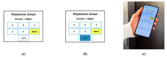
Figure 9.
Layout of the web interface of the IoT device: (a) user view with all buttons inactive; (b) user view after pressing the “open door button”, showing 2 s of remaining time until automatic door closure; (c) smartphone user view of the web interface.
4.6. IoT Device: Software Design
Figure 10 shows a simplified flowchart of the IoT software design. The software running on the control module is based on the Arduino framework for ESP32 and is written in C++; WiFi connection and network management were provided by the WiFi library integrated in the Arduino package. This library handles the connection to the building’s network and manages the transmission and reception of data packages. The ESPAsyncWebServer library was used for the low-level web interface management. It handles the http requests to the IoT device and sends back the web interface (described previously) to control the elevator. The library also receives the web events submitted by the web interface (which may include a control command), decodes the command, and activates the servomotor in order to press the physical buttons of the elevator button panel. The deactivation of the servomotor is handled by a dedicated timer for each of the buttons. As a safety feature, the ESP32 watchdog timer (WDT) can also deactivate the button in case of device malfunction in order to avoid blocking the elevator.
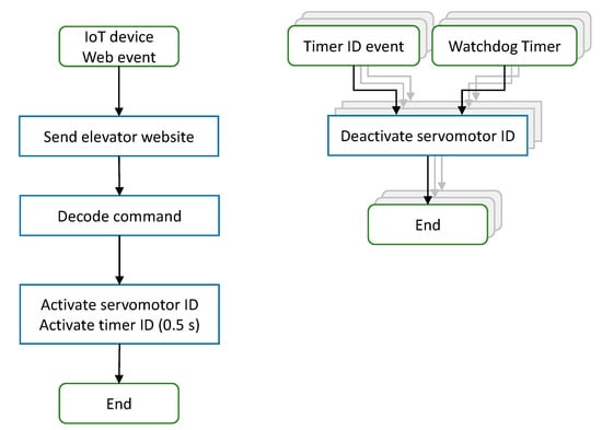
Figure 10.
IoT device software flow chart.
4.7. IoT Device: Control Protocol
The IoT device is controlled by sending http requests to the web server hosted in the controller module. This web server is accessed using an internal IP address. Both the IoT device and the user must be connected to the same network in order to interact with the elevator. Requests can be submitted from a standard web browser or another device such as a mobile robot navigating across multiple floors. Table 1 lists the commands defined.

Table 1.
Elevator commands. Web addresses are only accessible in the building.
4.8. IoT Device: Direct QR Code Access
The implementation of a direct QR code access is proposed in order to avoid the need to install proprietary APPs in smartphones or to remember the name or IP address of the web interface of the elevator. In this proposal, reading the QR codes automatically calls the elevator to further increase its accessibility.
Figure 11 shows the QR codes that represent some of the http commands described in Table 1. Each QR code generates a request to send the elevator to the floor in which the QR code is. The code is attached next to the elevator; to call the elevator, the user simply needs to scan the QR code with a QR reader. This code calls the elevator and opens the web interface of the IoT device for later destination selection.
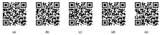
Figure 11.
QR codes for direct elevator call and web interface launching from: (a) basement; (b) ground floor; (c) first floor; (d) second floor; (e) third floor. Web addresses are only accessible in the building.
5. Experimental Application Results
Figure 12 shows the IoT device installed in one elevator of the Polytechnic School of the University of Lleida. The right-side elevator includes the add-on IoT device hung on the handrail, covering the lower elevator button panel. The performance of the IoT device was assessed under different real operation conditions by performing different experiments. The tests conducted evaluated the power consumption, the control of the device through a smartphone, the size of the QR code, and the machine-to-machine access to the IoT device.
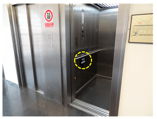
Figure 12.
Front view of the right-side elevator (or elevator 1) with the IoT device placed over the lower button panel of the car (yellow circle).
5.1. Evaluation of Power Consumption
Figure 13 shows the evolution of the current required by the IoT device during the activation of one button of the elevator. This current is drawn from a 5V battery. In this case, the IoT device never enters sleep mode thanks to the large capacity of the internal battery. This implementation optimizes the latency (response time) of the IoT device because there is no internal wake-up delay. The different internal states of the IoT device have been illustrated. In (i), the device remains in an idle state, waiting for elevator commands. In this state the base current consumption is 150 mA. In (ii), the device answers a “press button” command, one servomotor starts rotating and the intensity reaches a peak of 600 mA. The intensity value decreases to 200 mA when the servomotor reaches a constant velocity and increases when the servomotor starts pushing the physical button of the elevator. In (iii), the servomotor has reached the target angular orientation and the button of the elevator control panel is being pressed. In this state the servomotor is kept stationary and its internal closed loop control provides pulses (up to 600 mA) in order to maintain the angular orientation of the servomotor. The average current drawn in the state (iii) is approximately 250 mA. The servomotor is automatically released approximately 0.5 s after having received the “press button” command. In (iv), the servomotor is accelerated to return to its resting position. Figure 13 shows that the internal closed loop control of the servomotor provides current pulses (up to 800 mA) to stop its free rotation. After that, the IoT device returns to the idle state (i) and waits until the reception of the next command message.
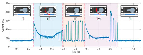
Figure 13.
Instantaneous current consumption by the IoT device during a button press. Servomotor cyclic states: (i) idle, (ii) activation, (iii) button pressed, and (iv) deactivation.
5.2. Evaluation of the Control through Smartphone
The evaluation of the control of the elevator through a smartphone was tested using the web interface (Figure 9c) and by defining two experiments: calling the elevator (accessing the IoT device to control the elevator from one floor, outside the car) and using the elevator (accessing the IoT device to control the elevator from inside the car). These experiments required the smartphone and the IoT device controlling the elevator to be connected to the wireless network of the building. In general, some connection problems can be expected when the elevator doors are closed. These experiments analyze and quantify such connection problems.
5.2.1. Calling the Elevator from Outside the Car
In the experiment designed to evaluate the IoT device controlling the elevator from outside the car, the floor where the smartphone is and the floor where the elevator is located are known. The experiment is proposed to experimentally evaluate all the possible combinations in which a user carrying a smartphone is in front of the elevator door calling it from outside the car. Table 2 shows the success rates of this experiment. In general, the success rates were very high, but in some of the combinations the WiFi connection experienced problems. In some cases, connection was lost for a few seconds and the web interface took 2–3 s to appear or respond. In other cases, the connection was lost for more than 10 s and the web interface had to be manually reloaded. These results are analyzed in the discussion and conclusion section.
Table 2.
Success rate when accessing to the IoT device controlling the elevator with a smartphone from outside of the car.
5.2.2. Using the Elevator from Inside the Car
In this experiment designed to evaluate the IoT device controlling the elevator from inside the car, the floor where the smartphone is and the floor where the elevator is located are known. The experiment is proposed to evaluate all the possible calling combinations in which a user carrying a smartphone is inside the elevator car. Table 3 shows the success rates of this evaluation experiment. In general, the success rates were again very high but in some of the combinations the WiFi connection experienced the same problems as in the previous experiment.
Table 3.
Success rate when accessing to the IoT device controlling the elevator with a smartphone from inside the car.
5.3. Evaluation of the Latency of the IoT Device
Figure 14 shows the evolution of the latency of the IoT device evaluated using the ping software utility to test the reachability of the IoT device placed inside a car of the elevator with the doors closed. This software utility is available for virtually all operating systems that provide network access. Ping measures the round-trip time for messages sent from a host to a destination device and echoed back to the host. Figure 14 shows the latency of the IoT device evaluated at the different floors of the building. The results show the following packet loss depending on the floor: 26% on Floor −1, 0% on Floor 0, 0% on Floor 1, 0% on Floor 2, and 0% on Floor 3. These packet loss results agree with the results obtained in the previous sections when accessing the IoT device of the elevator at the basement floor of the building. Regarding the packets successfully received, the average latency of the IoT device evaluated in the WiFi network of the building was 266 ms.
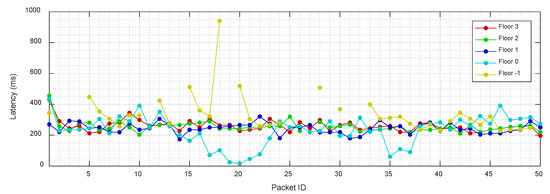
Figure 14.
Evolution of the latency of the IoT device.
5.4. Evaluation of the QR Code
Figure 15 shows a user calling the elevator by reading the QR code on the second floor of the building. The QR code automatically calls the elevator and opens its web interface to select the destination when entering the car. The QR codes displayed in Figure 11 were printed and evaluated using different sizes between 1 × 1 cm and 7 × 7 cm increasing in 1 cm steps. Figure 16 summarizes the sizes of the QR evaluated and the minimum, maximum, and mean scanning distances at which each QR code was successfully read with the front camera (16 Mpx) of a smartphone. The results show that a QR code of 7 × 7 cm (Figure 15) can be read with a 100% success at a distance range from 0.22 m to 2.5 m. Therefore, there is no need to get closer to the elevator to use the QR code feature to call it through the IoT device.
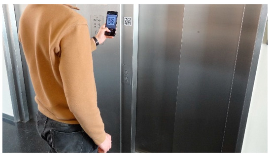
Figure 15.
User with a mobile phone reading the QR code (at 0.3 m) to call the elevator.
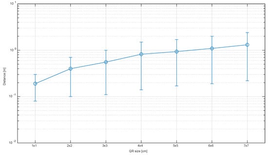
Figure 16.
Minimum, maximum, and average successful scanning distances for different QR sizes.
5.5. Evaluation of the Machine-to-Machine Access
The IoT device for remote elevator control can be accessed from any machine connected to the same wireless network than the IoT device. This capability was tested by implementing an experiment based on the use of a mobile robot calling the elevator. The mobile robot used for this experiment is the APR-02 mobile robot [56] developed at the Robotics Laboratory of the University of Lleida. This mobile robot is a human-sized (1.76 m, 30 Kg) omnidirectional platform with the capability to navigate autonomously through tight spaces [57,58,59]. In the near future, the mobile robot is expected to use the IoT device for elevator control to navigate across different floors within the building.
In this validation experiment, the mobile robot is located in front of the elevator (Figure 17), calling it through the IoT device. The calls to the elevator were implemented by using the transmission control protocol (TCP), that verifies the reception of the messages and resends them in case of error. In this experiment the access to the elevator was successful in 100% of the calls.
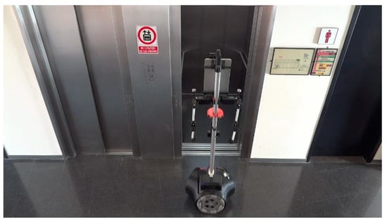
Figure 17.
APR-02 mobile robot calling the elevator through the IoT device for elevator control.
6. Discussion and Conclusions
This work proposes a non-contact and non-intrusive add-on Internet-of-Things (IoT) device for wireless remote control of an elevator. The IoT device has been designed as a non-intrusive add-on tool to be placed over the original elevator button panel. This proposal has the advantage of not requiring any physical manipulation or wiring connection of the original elevator infrastructure. Relative to comparable works [4,5,7], this specific feature provides a rapid response tool in order to increase the accessibility to elevators. The experimental evaluation of the IoT device in real operation conditions has validated its non-contact control features.
The IoT device is based on the use of a battery, one ESP32-S2-WOVER board as a control module, and several analog low-cost servomotors to press the original buttons of the elevator control panel. The control module provides connectivity to the wireless network used in the building and a simple web interface representing the buttons of the elevator control panel. The IoT device described in this paper has been designed to fit over the original lower button panel of the elevator located at the Polytechnic School of the University of Lleida. In this case, the button panel comprises 7 buttons: 5 to access the 5 floors of the building and two additional buttons to keep the door open and to activate the emergency alarm. The casing of the IoT device has been designed to replicate the original buttons of the control panel with cantilever-like buttons that can be used to manually interact with the original panel in case the IoT device runs out of battery. In this application case, the elevator car has two control panels. The IoT device has been mounted over the lower one, hanging from the handrail and firmly attached to the wall with a suction cup. Other implementations may be fixed only with suction cups or magnets.
The IoT device for elevator control provides a communication protocol tailored to receive http requests (messages) to press and automatically release the elevator buttons. Two specific commands allow the (1) press and (2) release of the button that keeps the door of the elevator open. The use of standard http request allows the use of QR codes to call the elevator and directly access the web interface of the elevator. This approach has the advantage of avoiding the need to install proprietary APPs or to remember the name or IP address of the web interface of the elevator.
The IoT device was implemented and experimentally evaluated by users accessing the elevator with their smartphone and by a mobile robot calling the elevator. The evaluation of the access to the IoT device through a smartphone has been performed in two cases: calling the elevator from outside the car and using the elevator from inside the car. The overall success rate when calling the elevator from outside the car was 89.20% and the communication problems detected were that connection was lost for a few seconds (2.80%) and connection lost for more than 10 s (8.00%). Similarly, the overall success rate when using the elevator from inside the car was 92.74% and the communication problems detected were connection lost for a few seconds (3.63%) and connection lost for more than 10 s (3.63%). These communication problems were solved by either pressing the button on the web interface again or reloading it.
The communication problems registered during the experiments have been attributed to wireless connectivity problems in the building. Figure 18 shows a schematic diagram of the five plants of the building depicting the position of the access points (AP) (or antenna) that provide wireless access. The label APXC means that there is an AP in the Corridor (C) of the plant X, some meters away from the elevator, while the label APXL means that there is an AP in the lobby (L) of the elevator of the plant X. An inspection of the building infrastructure revealed that all the plants were designed to have one AP in the elevator lobby and another in the nearby corridor. However, in practice, there are only two floors with an AP in the elevator lobby area (AP2L and AP0L), three floors with an AP in the corridor (AP3C, AP2C and AP1C) and one floor without any nearby AP. This asymmetric distribution (see Figure 18) was the cause of the wireless network problems experienced depending on the floor where the smartphone and the elevator were. In practice, these non-critical wireless communication problems observed during the experimentation with the IoT device for elevator control could be avoided simply by revising the distribution of the access points in the building.
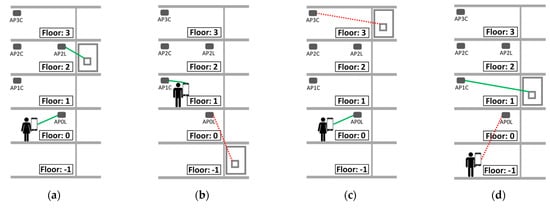
Figure 18.
Representation of the connection of the IoT device and a mobile phone to the WiFi of the building (green: successful connection, red: problematic connection): (a) successful connection; (b) the elevator may lose connection in the basement; (c) the elevator may lose connection on the third floor; (d) the smartphone may lose connection in the basement.
The possibility of using a QR code to automatically call the elevator and open its web interface was evaluated. In the case of this application, the white background of the QR code contrasts with the dark color of the walls and doors of the elevator, and the QR code was detected successfully from different distances. The results show that a relatively small QR code (7 × 7 cm, Figure 15) can be read with a 100% success from a distance ranging from 0.22 m to 2.5 m, so there is no need to get closer to the elevator to use the QR code feature.
In a last experiment, the machine-to-machine communication performance of the IoT device was evaluated with a mobile robot calling the elevator using TCP to send the control orders. In this case, the elevator was successfully accessed in 100% of the calls, probably because of the superior performance of the wireless antenna of the mobile robot and the automatic management of network communication errors performed by a TCP communication.
As a summary, the advantages of the IoT device proposed for elevator control are: (i) its relative low cost, because it is based on standard electronic devices and servomotors; (ii) its non-contact remote control performances; and (iii) its non-intrusive application in virtually any kind of elevator. These performances allow the device to be used as a rapid response tool in order to increase the non-contact accessibility to elevators. Conversely, the main drawback of the current implementation of the IoT device was its power consumption, which required the use of a large battery to ensure a weekly operation. In general, the strategy used to reduce the current on IoT devices is to make them enter sleep mode when not accessed and wake up when receiving a message. The disadvantage of this strategy is that it greatly increases the latency (response time) of the device, so it was discarded because the device had no size or battery limitation.
Finally, the non-contact add-on wireless IoT device proposed in this paper for remote elevator control has indirectly addressed the challenges identified by Kane et al. [39], as it avoids the need to locate and identify the elevator button panel and the challenges of interacting with its buttons.
6.1. Limitations
The IoT device for elevator control has some limitations. First, the current proposal is case-optimized and a general implementation of the device requires individual adaptation to each elevator button panel. Second, the battery of the device must be charged regularly in order to keep it operational after approximately one week. Third, the device is not optimized to operate in multi-elevator systems.
6.2. Future Works
Future works should address practical features such as the improvement of the power consumption of the servomotors and battery monitoring and managing. The current drawn by the device can be reduced by limiting the starting current of the analog servomotors and optimizing the profile of the horn pressing the original buttons of the control panel. A future work should also analyze the use of the IoT device for elevator control as a rapid-deployment tool to enable unsupervised multistory building navigation by service mobile robots. In this specific application case, the use of this IoT device avoids the development of a robotized arm and visual feedback procedures tailored to locate the button panels and properly pushing the buttons of the button panels. Finally, another work we would be interested in undertaking is the improvement of the device to assist people with disabilities in the use of elevators.
Author Contributions
Formal analysis, E.C. and J.P.; Investigation, E.R. and R.B.; Methodology, J.P.; Resources, J.P.; Software, R.B. and E.C.; Writing—original draft, E.R. and R.B.; Writing—review and editing, J.P. All authors have read and agreed to the published version of the manuscript.
Funding
This research was partially funded by the Departament de Recerca i Universitats de la Generalitat de Catalunya: FI SDUR 2022 grant.
Institutional Review Board Statement
Not applicable.
Informed Consent Statement
Not applicable.
Data Availability Statement
Not applicable.
Conflicts of Interest
The authors declare no conflict of interest. The funders had no role in the design of the study; in the collection, analyses, or interpretation of data; in the writing of the manuscript; or in the decision to publish the results.
References
- Froehlich, J.E.; Eisenberg, Y.; Hosseini, M.; Miranda, F.; Adams, M.; Caspi, A.; Dieterich, H.; Feldner, H.; Gonzalez, A.; De Gyves, C.; et al. The Future of Urban Accessibility for People with Disabilities: Data Collection, Analytics, Policy, and Tools. In Proceedings of the 24th International ACM SIGACCESS Conference on Computers and Accessibility, Athens, Greece, 23–26 October 2022. [Google Scholar] [CrossRef]
- Müller, K.; Engel, C.; Loitsch, C.; Stiefelhagen, R.; Weber, G. Traveling More Independently: A Study on the Diverse Needs and Challenges of People with Visual or Mobility Impairments in Unfamiliar Indoor Environments. ACM Trans. Access. Comput. 2022, 15, 1–44. [Google Scholar] [CrossRef]
- Stephens, L.; Spalding, K.; Aslam, H.; Scott, H.; Ruddick, S.; Young, N.L.; McKeever, P. Inaccessible childhoods: Evaluating accessibility in homes, schools and neighbourhoods with disabled children. Children’s Geogr. 2017, 15, 583–599. [Google Scholar] [CrossRef]
- Bo, W.; Li, Z. Design of the overall epidemic prevention system for the healthy operation of elevators. In Proceedings of the 2020 5th International Conference on Mechanical, Control and Computer Engineering (ICMCCE), Harbin, China, 25–27 December 2020; pp. 311–315. [Google Scholar] [CrossRef]
- Lai, S.-C.; Wu, H.-H.; Hsu, W.-L.; Wang, R.-J.; Shiau, Y.-C.; Ho, M.-C.; Hsieh, H.-N. Contact-Free Operation of Epidemic Prevention Elevator for Buildings. Buildings 2022, 12, 411. [Google Scholar] [CrossRef]
- Pearson, J.; Bailey, G.; Robinson, S.; Jones, M.; Owen, T.; Zhang, C.; Reitmaier, T.; Steer, C.; Carter, A.; Sahoo, D.R.; et al. Can’t Touch This: Rethinking Public Technology in a COVID-19 Era. In Proceedings of the Conference on Human Factors in Computing Systems, New Orleans, LA, USA, 29 April–5 May 2022. [Google Scholar] [CrossRef]
- Khelifi, A.; Muhamad, A.; Ehtesham, H.; Ghazal, M. A Reliable Handless System for Elevators Using Touchless Technology. In Proceedings of the 9th International Conference on Future Internet of Things and Cloud (FiCloud), Rome, Italy, 22–24 August 2022. [Google Scholar] [CrossRef]
- Zhou, Y.; Wang, K.; Liu, H. An Elevator Monitoring System Based on the Internet Of Things. Procedia Comput. Sci. 2018, 131, 541–544. [Google Scholar] [CrossRef]
- Teja, S.R.; Tez, D.S.P.; Nagarjuna, K.; Kumar, M.K.; Ahammad, S.H. Development of IoT Application for Online Monitoring of Elevator System. In Proceedings of the IEEE Mysore Sub Section International Conference, Mysuru, India, 16–17 October 2022. [Google Scholar] [CrossRef]
- Alsubaei, F.S.; Al-Wesabi, F.N.; Hilal, A.M. Deep Learning-Based Small Object Detection and Classification Model for Garbage Waste Management in Smart Cities and IoT Environment. Appl. Sci. 2022, 12, 2281. [Google Scholar] [CrossRef]
- Albulayhi, K.; Smadi, A.A.; Sheldon, F.T.; Abercrombie, R.K. IoT Intrusion Detection Taxonomy, Reference Architecture, and Analyses. Sensors 2021, 21, 6432. [Google Scholar] [CrossRef]
- Albulayhi, K.; Abu Al-Haija, Q.; Alsuhibany, S.A.; Jillepalli, A.A.; Ashrafuzzaman, M.; Sheldon, F.T. IoT Intrusion Detection Using Machine Learning with a Novel High Performing Feature Selection Method. Appl. Sci. 2022, 12, 5015. [Google Scholar] [CrossRef]
- Kim, M.; Kim, Y. Parcel Classification and Positioning of Intelligent Parcel Storage System Based on YOLOv5. Appl. Sci. 2023, 13, 437. [Google Scholar] [CrossRef]
- Sundari, M.S.; Mathana, J.M.; Nagarajan, T.S. Secured IoT Based Smart Greenhouse System with Image Inspection. In Proceedings of the 2020 6th International Conference on Advanced Computing and Communication Systems (ICACCS), Coimbatore, India, 6–7 March 2020; pp. 1080–1082. [Google Scholar] [CrossRef]
- Contreras-Castillo, J.; Guerrero-Ibañez, J.A.; Santana-Mancilla, P.C.; Anido-Rifón, L. SAgric-IoT: An IoT-Based Platform and Deep Learning for Greenhouse Monitoring. Appl. Sci. 2023, 13, 1961. [Google Scholar] [CrossRef]
- Kaushik, N.; Bagga, T. Smart Cities Using IoT. In Proceedings of the 2021 9th International Conference on Reliability, Infocom Technologies and Optimization (Trends and Future Directions) (ICRITO), Noida, India, 3 September 2021; pp. 1–6. [Google Scholar]
- Yasin, A.; Delaney, J.; Cheng, C.-T.; Pang, T.Y. The Design and Implementation of an IoT Sensor-Based Indoor Air Quality Monitoring System Using Off-the-Shelf Devices. Appl. Sci. 2022, 12, 9450. [Google Scholar] [CrossRef]
- Al-Kodmany, K. Tall Buildings and Elevators: A Review of Recent Technological Advances. Buildings 2015, 5, 1070–1104. [Google Scholar] [CrossRef]
- Bannister, P.; Bloomfield, C.; Chen, H. Empirical Prediction of Office Building Lift Energy Consumption. In Proceedings of the 12th Conference of International Building Performance Simulation Association, Sydney, Australia, 14–16 November 2011. [Google Scholar]
- Mitronikas, E.D.; Spyropoulos, D.V.; Papanikolaou, N.P.; Tatakis, E.C.; Spyropoulos, N. Energy saving during modern lift operation. In Proceedings of the 2014 International Conference on Electrical Machines (ICEM), Berlin, Germany, 2–5 September 2014. [Google Scholar] [CrossRef]
- Zhang, J.; Zong, Q. Energy-saving scheduling optimization under up-peak traffic for group elevator system in building. Energy Build. 2013, 66, 495–504. [Google Scholar] [CrossRef]
- Peters, R.; Smith, R.; Evans, E. The appraisal of lift passenger demand in modern office buildings. Build. Serv. Eng. Res. Technol. 2011, 32, 159–170. [Google Scholar] [CrossRef]
- Barney, G.; Al-Sharif, L. Elevator Traffic Handbook: Theory and Practice, 2nd ed.; Routledge: London, UK, 2015. [Google Scholar] [CrossRef]
- Jung, M.; Park, M.; Lee, H.S.; Chi, S. Agent-Based Lift System Simulation Model for High-Rise Building Construction Projects. J. Comput. Civ. Eng. 2017, 31, 04017064. [Google Scholar] [CrossRef]
- Esteban, E.; Salgado, O.; Iturrospe, A.; Isasa, I. Model-based approach for elevator performance estimation. Mech. Syst. Signal Process. 2016, 68–69, 125–137. [Google Scholar] [CrossRef]
- Hirasawa, K.; Eguchi, T.; Zhou, J.; Yu, L.; Hu, J.; Markon, S. A Double-Deck Elevator Group Supervisory Control System Using Genetic Network Programming. IEEE Trans. Syst. Man Cybern. Part C (Appl. Rev.) 2008, 38, 535–550. [Google Scholar] [CrossRef]
- Fan, H.; Chau, K.T.; Liu, C.; Cao, L.; Ching, T.W. Quantitative Comparison of Novel Dual-PM Linear Motors for Ropeless Elevator System. IEEE Trans. Magn. 2018, 54, 1–6. [Google Scholar] [CrossRef]
- Al-Sharif, L.; Alqumsan, A.M.A.; Aal, O.F.A. Automated optimal design methodology of elevator systems using rules and graphical methods (the HARint plane). Build. Serv. Eng. Res. Technol. 2013, 34, 275–293. [Google Scholar] [CrossRef]
- Tervonen, T.; Hakonen, H.; Lahdelma, R. Elevator planning with stochastic multicriteria acceptability analysis. Omega 2008, 36, 352–362. [Google Scholar] [CrossRef]
- Lee, D.-S.; Ji, K.-H.; Jing, J.; Jo, J.-H. Experimental study on elevator door reopening problems caused by stack induced pressure differences across the elevator door in buildings. Build. Environ. 2022, 221, 109271. [Google Scholar] [CrossRef]
- Au-Yong, C.P.; Azmi, N.F.; Mahassan, N.A. Maintenance of lift systems affecting resident satisfaction in low-cost high-rise residential buildings. J. Facil. Manag. 2018, 16, 17–25. [Google Scholar] [CrossRef]
- Kang, M.-W.; Oh, Y.-K. Validity of Elevator Noise Measurement Method in International Standards on High-Rise Residential Buildings. Sustainability 2021, 13, 9806. [Google Scholar] [CrossRef]
- Oh, Y.; Kang, M.; Lee, K.; Kim, S. Construction Management Solutions to Mitigate Elevator Noise and Vibration of High-Rise Residential Buildings. Sustainability 2020, 12, 8924. [Google Scholar] [CrossRef]
- Park, S.T.; Yang, B.S. An implementation of risk-based inspection for elevator maintenance. J. Mech. Sci. Technol. 2010, 24, 2367–2376. [Google Scholar] [CrossRef]
- Niu, G.; Lee, S.S.; Yang, B.S.; Lee, S.J. Decision fusion system for fault diagnosis of elevator traction machine. J. Mech. Sci. Technol. 2008, 22, 85–95. [Google Scholar] [CrossRef]
- Ding, N.; Chen, T.; Zhang, H. Experimental Study of Elevator Loading and Unloading Time During Evacuation in High-Rise Buildings. Fire Technol. 2017, 53, 29–42. [Google Scholar] [CrossRef]
- Chen, J.; Ma, J.; Lo, S.M. Event-driven modeling of elevator assisted evacuation in ultra high-rise buildings. Simul. Model. Pract. Theory 2017, 74, 99–116. [Google Scholar] [CrossRef]
- Ahmed, S.S.; Iqbal, A.; Sarwar, R.; Salam, M.S. Modeling the energy consumption of a lift. Energy Build. 2014, 71, 61–67. [Google Scholar] [CrossRef]
- Kane, S.K.; Guo, A.; Morris, M.R. Sense and Accessibility: Understanding People with Physical Disabilities’ Experiences with Sensing Systems. In Proceedings of the 22nd International ACM SIGACCESS Conference on Computers and Accessibility, Virtual Event, Greece, 26–28 October 2020. [Google Scholar] [CrossRef]
- Domingo, M.C. An overview of the Internet of Things for people with disabilities. J. Netw. Comput. Appl. 2012, 35, 584–596. [Google Scholar] [CrossRef]
- Yulianto, H.R.; Afiahayati. Fighting COVID-19: Convolutional Neural Network for Elevator User’s Speech Classification in Bahasa Indonesia. Procedia Comput. Sci. 2021, 189, 84–91. [Google Scholar] [CrossRef]
- Liu, Y.; Wang, W.; Li, Y. Realization of Contactless Elevator Control Panel System Based on Voice Interaction Technology. In Proceedings of the 3rd International Conference on Control Systems, Mathematical Modeling, Automation and Energy Efficiency (SUMMA), Lipetsk, Russia, 10–12 November 2021. [Google Scholar] [CrossRef]
- Shinde, A.S.; Jamdar, A.S.; Joshi, K.D.; Sarode, S.T. A CNN Based Speech Recognition Approach for Voice Controlled Elevator. In Proceedings of the 2021 5th International Conference on Electrical, Electronics, Communication, Computer Technologies and Optimization Techniques (ICEECCOT), Mysuru, India, 10–11 December 2021. [Google Scholar] [CrossRef]
- Meenatchi, D.; Aishwarya, R.; Shahina, A. A Voice Recognizing Elevator System. In Proceedings of the International Conference on Soft Computing Systems; Suresh, L., Panigrahi, B., Eds.; Advances in Intelligent Systems and Computing; Springer: New Delhi, India, 2016; Volume 397. [Google Scholar] [CrossRef]
- Chatziparasidis, I.; Sfampa, I.K. Residential buildings with brain-computer interface functionality: An elevator case study. Build. Serv. Eng. Res. Technol. 2022, 43, 261–272. [Google Scholar] [CrossRef]
- Nicolas-Alonso, L.F.; Gomez-Gil, J. Brain Computer Interfaces, a Review. Sensors 2012, 12, 1211–1279. [Google Scholar] [CrossRef]
- Zhang, X.; Wu, J.; Smith, L.M.; Li, X.; Yancey, O.; Franzblau, A.; Dvonch, J.T.; Xi, C.; Neitzel, R.L. Monitoring SARS-CoV-2 in air and on surfaces and estimating infection risk in buildings and buses on a university campus. J. Expo. Sci. Environ. Epidemiol. 2022, 32, 751–758. [Google Scholar] [CrossRef]
- Wang, C.C.; Prather, K.A.; Sznitman, J.; Jimenez, J.L.; Lakdawala, S.S.; Tufekci, Z.; Marr, L.C. Airborne transmission of respiratory viruses. Science 2021, 373, eabd9149. [Google Scholar] [CrossRef]
- Wu, S.; Wang, Y.; Jin, X.; Tian, J.; Liu, J.; Mao, Y. Environmental contamination by SARS-CoV-2 in a designated hospital for coronavirus disease 2019. Am. J. Infect. Control 2020, 48, 910–914. [Google Scholar] [CrossRef]
- Lavric, A.; Petrariu, A.I.; Mutescu, P.-M.; Coca, E.; Popa, V. Internet of Things Concept in the Context of the COVID-19 Pandemic: A Multi-Sensor Application Design. Sensors 2022, 22, 503. [Google Scholar] [CrossRef]
- Kuncoro, C.B.D.; Amaris, A.; Permana, A.F. Smart Wireless CO2 Sensor Node for IoT Based Strategic Monitoring Tool of The Risk of The Indoor SARS-CoV-2 Airborne Transmission. Appl. Sci. 2022, 12, 10784. [Google Scholar] [CrossRef]
- Akshat, A.; Nanda, V.; Singhal, A.; Jindal, S.K. AT89S52-Microcontroller Based Elevator with UV-C disinfection to prevent the transmission of COVID-19. In Proceedings of the 2020 International Conference on Interdisciplinary Cyber Physical Systems (ICPS), Chennai, India, 28–29 December 2020. [Google Scholar] [CrossRef]
- François, P.-M.; Bonnet, X.; Kosior, J.; Adam, J.; Khonsari, R.H. 3D-printed contact-free devices designed and dispatched against the COVID-19 pandemic: The 3D COVID initiative. J. Stomatol. Oral Maxillofac. Surg. 2021, 122, 381–385. [Google Scholar] [CrossRef]
- Organización Nacional de Ciegos Españoles. Technical Document B 17: Braille Signage on Lift Button Panels. Available online: https://www.once.es/ (accessed on 10 January 2023).
- Organización Nacional de Ciegos Españoles. Technical Document B 1: Parámetros Dimensionales del Braille. Available online: https://www.once.es/ (accessed on 10 January 2023). (In Spanish).
- Rubies, E.; Palacín, J.; Clotet, E. Enhancing the Sense of Attention from an Assistance Mobile Robot by Improving Eye-Gaze Contact from Its Iconic Face Displayed on a Flat Screen. Sensors 2022, 22, 4282. [Google Scholar] [CrossRef]
- Palacín, J.; Rubies, E.; Clotet, E.; Martínez, D. Evaluation of the Path-Tracking Accuracy of a Three-Wheeled Omnidirectional Mobile Robot Designed as a Personal Assistant. Sensors 2021, 21, 7216. [Google Scholar] [CrossRef]
- Palacín, J.; Rubies, E.; Clotet, E. Systematic Odometry Error Evaluation and Correction in a Human-Sized Three-Wheeled Omnidirectional Mobile Robot Using Flower-Shaped Calibration Trajectories. Appl. Sci. 2022, 12, 2606. [Google Scholar] [CrossRef]
- Palacín, J.; Rubies, E.; Bitrià, R.; Clotet, E. Non-Parametric Calibration of the Inverse Kinematic Matrix of a Three-Wheeled Omnidirectional Mobile Robot Based on Genetic Algorithms. Appl. Sci. 2023, 13, 1053. [Google Scholar] [CrossRef]


Disclaimer/Publisher’s Note: The statements, opinions and data contained in all publications are solely those of the individual author(s) and contributor(s) and not of MDPI and/or the editor(s). MDPI and/or the editor(s) disclaim responsibility for any injury to people or property resulting from any ideas, methods, instructions or products referred to in the content. |
© 2023 by the authors. Licensee MDPI, Basel, Switzerland. This article is an open access article distributed under the terms and conditions of the Creative Commons Attribution (CC BY) license (https://creativecommons.org/licenses/by/4.0/).