Abstract
The tensile strength and fracture properties of the c-ZrO2(001)/α-Al2O3() interfaces were investigated by first-principle tensile simulations. Models with different stacking sequences of c-ZrO2(001) were examined. The theoretical tensile strength and work of adhesion were present. It was found that the adhesive strength of the interface was strongly influenced by the termination of c-ZrO2(001), and the c-ZrO2(001)/α-Al2O3() interfaces adhered weakly. Then, variations of the atomic bonds were observed to clarify the fracture characteristics of the interfaces. Our study indicates that the fracture modes of the O- and Zr-model tend to be ductile fractures, while the fracture mode of the 2O-model is a brittle fracture. Furthermore, all three models were completely separated along the intermediate layer between the initial ZrO2 and Al2O3 slabs. Finally, we compared our results with those available in the published literature, and the potential application of the first-principle results will be further discussed.
1. Introduction
The thermal barrier coating (TBC) is a high-temperature protection technology widely used in gas turbine engines to protect hot components, such as combustors, nozzles, vanes, and turbine blades [1,2,3,4,5,6,7]. The TBC enables the engines to achieve greater efficiency by insulating the engine components from prolonged thermal loads. Typical TBC systems include a nickel-based superalloy substrate, a NiCrAlY or NiCoCrAlY bond coat (BC), a thermally grown oxide (TGO), and a Yttria-stabilized zirconia (YSZ) ceramic top coat (TC) [8]. The function of the BC is to prevent oxidation corrosion of the substrate and alleviate thermal expansion mismatch (TEM). The TC is the heat insulation layer between the hot gas and substrate. Since the TBC is usually operated in harsh environments, premature failure is inevitable. Therefore, understanding the failure mechanism of the TBC is crucial to help us improve and optimize the TBC system to meet engineering requirements.
During the service of the TBC, the growth of TGO [9,10], phase transformation [11,12], infiltration of calcium–magnesium–alumina–silicate (CMAS) [13,14], residual stress [15,16], and high-temperature sintering [17,18] affect the life of the TBC and eventually lead to the TBC’s spallation and delamination. Among them, the growth of TGO is the key factor. With the increase of TGO’s thickness, the thermal expansion mismatch (TEM) occurs between the TC/TGO/BC and eventually leads to a TBC fracture at the TGO/BC and TC/TGO interfaces [19]. Therefore, it is of great significance to investigate the mechanical properties and failure mechanisms of these two interfaces. It is still a challenge to obtain the failure mechanism of the interface directly by experiments due to the lack of experimental conditions. Instead, first-principle calculations can reveal the basic physical properties of interface structures, such as electronic, atomic structure, and mechanical properties, and have been applied to study the failure mechanism of interfaces [20,21,22,23,24]. Yang et al. [21] found that the tensile strength of the Al-terminated Cu/Al2O3 is weaker than the O-terminated interface, and the mechanical properties of the Al-terminated interface are mainly dominated by the Cu-Al electronic hybridization interactions. Shi et al. [22] concluded that the tensile strength and failure mechanism of the Ni/Al2O3 interface were strongly influenced by the termination of α-Al2O3(0001). The failure of the Al-terminated O-site interface occurred at the interface under lower stress, while the failure of the O-terminated Al-site interface occurred within the Ni layer. Li et al. [23] found that the ideal tensile strength and adsorption work of the O-terminated γ-Fe/α-Al2O3 interface are 3.5 times and 5 times those of the Al-terminated interface, respectively. The fracture mode of the Al-terminated interface tends to be a brittle fracture, while the O-terminated interface is more like a ductile fracture. Ji et al. [24] found that Ti-terminated TiSiC2 and O-terminated Al2O3 are the most stable of their respective crystals. The higher work of adhesion of the TiSiC2/Al2O3 interface is due to the powerful attraction between the Ti and O atoms on the interface. Our research group has examined the mechanical strength and fracture characteristics of the Ni/Al2O3 interface under tensile, shear, and mixed mode loadings by first-principle calculations [25,26,27,28]. In general, the first-principle tensile simulation is an accurate and effective method to investigate the tensile strength and failure mechanism of the interface. However, few studies have considered the TC/TGO interface. Gao et al. [29] concluded that the adhesion of the ZrO2/Al2O3 interfaces is sensitive to the atomic layer’s thickness. The increase of ZrO2′s layer thickness enhances the adhesion of the ZrO2/Al2O3 interfaces, while the increase of Al2O3′s layer thickness weakens the interface adhesion. Using all-electron projector augmented wave formalism within the density functional theory, Christensen et al. [30] found that the ZrO2/Al2O3 interfaces are weakly bonded, and the work of adhesion is independent of the ZrO2 layer thickness. Nevertheless, the tensile strength and failure mechanism of the ZrO2/Al2O3 interfaces have not been investigated up to now.
In this paper, the tensile simulations for three types of the c-ZrO2(001)/α-Al2O3() interfaces are carried out using first-principle calculations. The ideal tensile strength and work of separation are obtained and discussed in detail. Furthermore, we observe the evolution of the atomic structures of these interface models during the tension process and discuss the failure characteristics of these interface models. In addition, our results are compared with those available in the literature, and the potential application of the first-principle results is further discussed.
2. Methodology and Model
2.1. First-Principle Tensile Simulation
In this study, we examined the ZrO2/Al2O3 interfaces using the Vienna Ab Initio Simulation Package (VASP) [31,32]. The all-electron projector augmented wave (PAW) method was adopted to describe the interactions between the nuclei and valence electrons. The generalized gradient approximation (GGA) was used for the electron exchange and correlation. The 5 × 5 × 1 Monkhost-Pack scheme was adopted to realize the k-point sampling in the Brillouin zone. The cutoff energy for the plane-wave basis was (500 eV), and the self-consistent energy relaxation criterion for the electron was 10−5 eV. Relaxation was performed using the conjugate gradient (CG) algorithm, and the convergence criterion was a Hellman–Feynman force of less than 0.01 eV/Å.
2.2. Simulation Model
Considering that the structure and composition of real TC/TGO interfaces could be very complex, we focused on the relevant ZrO2/Al2O3 interfaces in this paper. For Al2O3, only α-Al2O3 was considered, since α-Al2O3 is the most stable phase, and other Al2O3 phases have a more complicated, mostly ill-characterized bulk structure. ZrO2 typically has three phases at low pressure conditions, i.e., cubic, tetragonal, and monoclinic. On the α-Al2O3 substrate, the epitaxial growth of the deposited YSZ(001) has been observed as α-Al2O3()/YSZ(001) [33]. Moreover, the lattice constant of YSZ(001) is approximately the same as that of c-ZrO2(001). In addition, the mismatch ratio between c-ZrO2(001) and α-Al2O3() is about 3.7%. Taking the above aspects into consideration, we focused on the c-ZrO2(001)/α-Al2O3() interfaces.
According to preliminary calculations, the calculated lattice constants of c-ZrO2 were a0 = 5.07 Å, while those of α-Al2O3 were a0 = 4.809 Å and c0 = 13.115 Å. In addition, the suitable atomic relaxation layers of the c-ZrO2 slab and the α-Al2O3 slab were nine and fifteen layers, respectively. Our calculated values agree well with available experimental values and other first-principle results [30,34,35,36]. The thickness of fifteen layers of α-Al2O3 is 10.5 Å, corresponding to three α-Al2O3() units. This thickness is usually sufficient to simulate a bulk ceramic surface in terms of electronic structure and ionic relaxation effects [37]. Figure 1 displays the schematic diagrams of the c-ZrO2(001)/α-Al2O3() interfaces. The supercell consists of a slab of α-Al2O3() sandwiched between two slabs of α-Al2O3(). The layering sequence in the α-Al2O3() surface termination was |O—Al—O—Al—O|O—Al—O—Al—O|.... Compared to α-Al2O3()’s surface termination, c-ZrO2 (001)’s surface termination is more complicated. The layering sequence in c-ZrO2(001)’s surface termination was Zr-O-Zr-..., O-Zr-O-..., and 2O-Zr-... [38], as shown in Figure 1b–d. In this paper, three types of c-ZrO2(001)/α-Al2O3()-terminated interfaces are considered. In the following, we will refer to these three possibilities as the Zr-terminated, O-terminated, and 2O-terminated interfaces. In this simulation, a tensile load was applied to make the supercell expand gradually along the loading direction, and then the supercell was fully relaxed until the convergence criterion was satisfied. This process was repeated until the interface was completely broken.
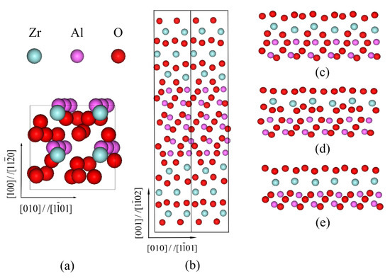
Figure 1.
The schematic diagrams of c-ZrO2(001)/α-Al2O3() interfaces. (a) Top view; (b) front view; (c) O-terminated; (d) 2O-terminated; (e) Zr-terminated. The blue, pink, and red spheres represent Zr, Al, and O atoms, respectively.
3. Results
3.1. Tensile Strength Parameter
The stress–strain curves of the three terminated c-ZrO2(001)/α-Al2O3() interfaces are shown in Figure 2. The curves were obtained by applying uniaxial tension to the three models. The stress of the O-terminated interface reached a maximum value of 9.012 GPa when the strain was 9%, while for the Zr-terminated and 2O-terminated interfaces, the stresses reached a maximum value of 6.893 GPa and 7.452 GPa at the strains of 5% and 6%, respectively. Among the three models, the O-terminated interface has the greatest theoretical tensile strength and critical strain. This implies that the adhesion of the O-model is stronger compared to the other two models, and the tensile strength of the superlattice is strongly influenced by the termination of c-ZrO2(001). Moreover, the curve shapes of the three terminated interfaces are rather similar to each other, which was also mentioned by Shi [22]. In addition, the curve also indicates some information about the failure behavior. Different from the O-terminated and Zr-terminated interfaces, the stress of the 2O-terminated interface has a sudden drop after the critical strain. This implies that the fracture type of the 2O-terminated interface is different from that of the other two terminated interfaces during the tension loading.
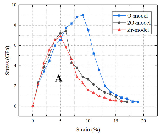
Figure 2.
Stress–strain curves of the three terminated c-ZrO2(001)/α-Al2O3() interfaces. The letter A represents the area under the stress–strain curve.
The work of separation, Wsep, is an important parameter for analyzing the interface strength, which is defined as the energy required to separate the interface into two free surfaces. Furthermore, the area, A, under the stress–strain curve can approximate the value of the work of separation [20]. In this work, the calculated work of separation for the O-terminated interface is 1208 mJ/m2, while that for the Zr-terminated and 2O-terminated interfaces are 715 mJ/m2 and 829 mJ/m2, respectively.
Combining the calculated tensile strength and work of separation, we can conclude that the fracture mode of the 2O-terminated interface is different from that of the other two terminated interfaces. Among the three terminated interfaces, the O-terminated interface has the strongest resistance to tensile failure, while the Zr-terminated interface is the most prone to failure.
3.2. Fracture Characteristic
By fully relaxing the entire slab, the bond lengths and interface distance of the three terminated interfaces were obtained, and the results are collected in Table 1.

Table 1.
Bond lengths (Å) of the three models in the interface region.
The bond lengths in the interface region for the three terminated interfaces listed in Table 1 are divided according to whether the bond is parallel to or across the interface. The ranges of the bond lengths are observed parallel to the interfaces. The ranges on the Al2O3 side are mostly limited by bulk values (1.856 and 1.969 Å), while the ranges on the ZrO2 side are shorter than the bulk values. The results show that no obvious tendency is found in the variation in the stacking sequence of ZrO2. The Al cations near the interfaces tend to bond with the O anions in c-ZrO2 (except the Zr-terminated interface), and the O anions in α-Al2O3 near the interfaces tend to bond with the Zr cations. Moreover, the cation–cation interaction (Al-Zr) is found in the O-terminated and Zr-terminated interfaces, adding stability to the structure.
In order to better understand the failure process of the c-ZrO2/α-Al2O3 interfaces under the tensile loading, we investigated the details of the interfacial atomic bonds. Figure 3 shows the interfacial bond length differentials in the interface region during the tension loading process, and the evolution of the interfacial atomic bonds during the tension process is plotted in Figure 4.
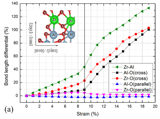
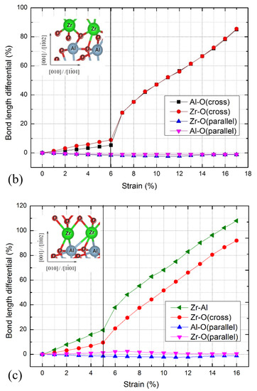
Figure 3.
Interfacial bond length differentials for c-ZrO2(001)/α-Al2O3() interfaces during the stretching process. (a) O-terminated, (b) 2O-terminated, and (c) Zr-terminated. The vertical line indicates the critical strain. Pictorial showing the interfacial bonds is shown in the inset panel. The green, grey, and red spheres represent Zr, Al, and O atoms, respectively.
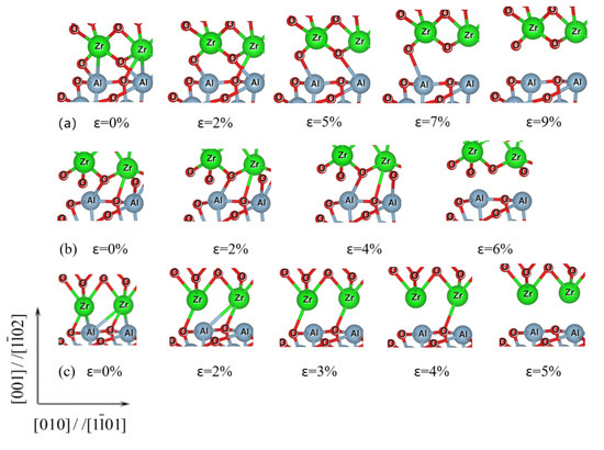
Figure 4.
Pictorial representation showing the evolution of the interfacial atomic bonds for the c-ZrO2/α-Al2O3 interfaces under the tension loading. (a) O-terminated, (b) 2O-terminated, and (c) Zr-terminated.
For the O-terminated interface shown in Figure 3a, the bond lengths of the Al-O bond parallel to the interface are almost unchanged, while the atomic bond lengths of the other bonds increase gradually. The bond lengths of the Zr-O bond parallel to the interface begin to shrink when the strain exceeds 8%, and the bond lengths of the Al-O, Zr-O, and Zr-Al bonds across the interface increase rapidly. When reaching the critical strain of 9%, the atomic bond breaking occurs at the Al-O, Zr-O, and Zr-Al bonds across the interface break. Combined with Figure 2, the stress gradually decreases after the critical strain of 9%, indicating that the failure mode of the interface is similar to the ductile fracture. The Zr-terminated interface has a similar fracture process, as shown in Figure 3c, and the atomic bond breaking takes place at the Al-O, Zr-O, and Zr-Al bonds across the interface. While for the 2O-terminated interface shown in Figure 3b, when exceeding the critical strain of 6%, the bond lengths of the Al-O and Zr-Al bonds across the interface increase rapidly and the stresses drop abruptly (Figure 2), demonstrating that the brittle fracture occurs at this interface.
Figure 4 shows the evolution of the atomic bonds for the c-ZrO2(001)/α-Al2O3() interfaces under tensile loading. For the O-terminated interface, as seen in Figure 4a, the weaker Zr-Al bonds break at first when the strain reaches 2%. With the increase of the tensile load, the Zr-O bond across the interface breaks. After that, one of the Al–O bonds breaks with the increasing tensile load. Finally, the other Al–O bonds across the ZrO2/Al2O3 interfaces also break when the strain reaches the critical strain of 9%. The interfacial atomic bonds break down gradually during the tension loading process, which also indicates that the fracture mode of the O-terminated interface tends to be a ductile fracture. The atomic bonds in the Zr-terminated interface have a similar gradual breakage process, as shown in Figure 4c. Compared with the gradual breakage mode of the O-terminated and Zr-terminated interfaces, the fracture characteristic of the 2O-terminated interface is quite different. For the 2O-terminated interface (Figure 4b), all the atomic bonds across the interface remain intact until the strain reaches the critical strain of 6%, signifying that a brittle fracture has occurred.
Combined with Figure 2, Figure 3 and Figure 4, when the applied stress reaches a sufficient value of 9.012 GPa, the O-terminated interface becomes separated along the intermediate layer between the initial ZrO2 and Al2O3 slabs. That is to say, the failure occurs exactly at the interface for this termination. Furthermore, this feature is shown in all three interface terminations.
4. Discussion
In this study, we examined the tensile strength and failure properties of the three terminated ZrO2/Al2O3 interfaces using first-principle calculations. Among the three interface terminations, the calculated results indicate that the O-terminated interface has the strongest resistance to tensile failure, while the Zr-terminated interface is the most prone to failure. Due to the bond energy of the anion–cation, the bonds across the interfaces in the O-model are stronger than those of the other two models. Moreover, the stabilizing cation–cation interactions across the interface also increase the adhesive energy of the O-model. In addition, the failure position of the three interface terminations occurs at the interface, indicating the weak adhesion of the interface. In addition, the fracture modes of the O-terminated and Zr-terminated interfaces tend to be ductile fractures, while the fracture mode of the 2O-terminated interface tends to be a brittle fracture.
In our shear simulations [39], the O- <110> model had a maximum shear strength of 5.69 GPa and unstable stacking energy of 612 mJ/m2. The Zr- <101> model had a minimum shear strength of 2.94 GPa and work of adhesion of 245 mJ/m2. It was found that the shear strength of the c-ZrO2(001)/α-Al2O3() interfaces had the same trend; that is, the O-terminated interface had the greatest shear resistance, while the Zr-terminated interface had the weakest shear resistance. However, compared with the shear strength, the tensile strength was much higher than the shear strength in the same termination. This implies that the c-ZrO2(001)/α-Al2O3() interfaces have a stronger tensile resistance and are more prone to shear failure. According to our investigations through these first-principle calculations, shear failure requires only the breaking of some bonds at the interface, whereas tensile failure requires the breakage of all the bonds near the interface.
Christensen et al. investigated the ZrO2(001)/α-Al2O3() interfaces by first-principles calculations to understand the electronic, structural, and energy properties [30]. Their calculated adiabatic work of adhesion was about 1200 mJ/m2. Our calculated work of adhesion for the O-terminated interface was consistent with this value. In order to fully investigate the mechanical properties of the c-ZrO2(001)/α-Al2O3() interfaces, we also examined the Zr-terminated and 2O-terminated interfaces. The calculated results imply that the adhesive strength of the interface is strongly influenced by the termination of c-ZrO2(001), while the interfaces of all the models adhered weakly. In fact, when looking closely at the atomic snapshots of these interfaces, it is seen that the length increments of the two Al-O bonds are quite different at each displacement loading step. The three terminations are completely separated along the intermediate layer between the initial ZrO2 and Al2O3 slabs. This also suggests that the interaction between ZrO2 and Al2O3 is weak. Moreover, as the interface in the TBC system, this weak interaction absolutely affects the lifetime of the TBC system. Another interface in the TBC system, i.e., the Ni(111)/α-Al2O3(0001) interface, has been investigated by Guo et al. [25] through a comparative study between the uniaxial extension and uniaxial tension simulations. In their work, the peak stress of the Al-terminated O-site model is 9.915 GPa at the strain of 11% under uniaxial tension, and the work of adhesion is 1.48 J/m2. For the O-terminated Al-site model, the peak stress is 23.384 GPa at the strain of 14%, and the work of adhesion is 4.17 J/m2. Then, the failure position of the Al–O model occurs at the interface, while the failure of the O-Al model occurs within the Ni layer. Their results indicate that the Al–O model is weakly adhered, while the O-Al model has much higher strength. Compared to their results, the bonding strength of the ZrO2/Al2O3 interfaces is weaker than that of the Ni/Al2O3 interface. This indicates that the TBC is more prone to failure at the ZrO2/Al2O3 interfaces. However, considering the weak adhesion of the Al–O model, the failure of the TBC system may occur at any interface. The comprehensive consideration of the mechanical properties of the two interfaces will help us to understand the details of the failure process of the TBC and provide data for the optimization and improvement of the TBC system.
In molecular dynamic simulations, interatomic interactions are described by atomic potential functions. However, the empirical potentials used often cannot accurately describe the interactions between dissimilar atoms, such as the Zr-Al, Al-O, and Zr-O bonds in this paper. Sun et al. [40] creatively used atomic models to estimate the tension–shear coupling. According to their theory, the potential function is defined as:
Here, and are the shear displacement and tensile displacement, respectively. Wsep is the work of separation, L is the displacement value corresponding to the maximum tensile stress, b is the Burgers vector, and p and q are important parameters for measuring tension–shear coupling. For the pure tensile separation, the potential function can be simplified as [41]:
Furthermore, the tensile stress is derived from Equation (2) as:
In this work, the work of separation, Wsep, and the theoretical tensile strength for the three interface terminations were calculated, and the value of the L can be obtained by fitting it to our first-principle results. Figure 5 shows the potential energy-displacement curve of the three terminated c-ZrO2(001)/α-Al2O3() interfaces. Although the analytical curves do not exactly match the first-principle results, it is quite satisfactory in terms of the curve trend and maximum potential value. To further check the applicability of the above potential function, the tensile stress-displacement analytical curves of the three interface models based on Equation (3) are shown in Figure 6, which resemble, very much, the first-principle calculation results in shape. In addition, the analytical curves are in good agreement with the first-principle calculation results, both in terms of peak stress and curve area (Wsep), although there is a subtle difference between the displacements corresponding to the peak stress. This may be because the analytic expression does not take into account the relaxation effects. The reproduction of the peak stress and Wsep proves the accuracy of this potential function. It is thus believed that the potential function of c-ZrO2(001)/α-Al2O3() constructed from our first-principle results is a reliable one. Of course, it would be rewarding to examine the source of the existing difference and to further improve the above form of the potential function.
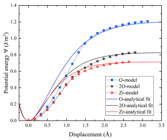
Figure 5.
The potential energy-displacement curve of the three terminated c-ZrO2(001)/α-Al2O3() interfaces. The analytical curves based on Equation (2) and the curves from first-principle calculations are shown as well.
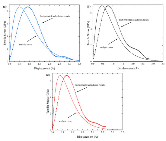
Figure 6.
The tensile stress-displacement analytical curves and the first-principle results of c-ZrO2(001)/α-Al2O3() interfaces. The analytical curves based on Equation (3) and the curves from first-principle calculations are shown as well. (a) O-terminated, (b) 2O-terminated, and (c) Zr-terminated.
In addition, our computational results can be used to construct the cohesive law of the c-ZrO2(001)/α-Al2O3() interfaces [42,43,44]. The fracture energy governing the equation of exponential cohesive zone models (CZMs) in the cracking process is [45]:
The parameters in this equation are rather consistent with those in Equation (1). As in the case of pure tensile separation, the form of this equation is exactly the same as Equation (2). The accuracy of this potential function has been demonstrated by the analysis of Figure 5 and Figure 6. Therefore, the CZMs based on the first-principle results will naturally have higher accuracy.
To go on one step further, the potential function based on the first-principle calculations can be used to predict the interface toughness. Jiang et al. [46] incorporated their first-principle calculation result into the macroscopic toughness calculation model by constructing an accurate potential function, and the toughness of the -Ni(Al)/α-Al2O3 interface was predicted successively. By following the same way, the toughness of c-ZrO2(001)/α-Al2O3() can also be predicted with the aid of the above first-principle outputs.
In this study, we performed first-principle tensile simulations of the three terminated c-ZrO2(001)/α-Al2O3() interfaces. In practice, in the process of TBC failure, not only tensile failure but also shear failure occurs. Therefore, the shear failure and tension–shear coupling failure of c-ZrO2(001)/α-Al2O3() interfaces will be investigated next, which will be important for a comprehensive understanding of the c-ZrO2(001)/α-Al2O3() interfaces and finally provide more information for optimizing and improving the TBC.
5. Conclusions
Three types of c-ZrO2(001)/α-Al2O3() interfaces have been investigated by first-principle calculations. The O-terminated interface has the greatest theoretical tensile strength of 9.012 GPa and work of adhesion of 1208 mJ/m2. The Zr-terminated interface has the least theoretical tensile strength of 6.893 GPa and work of adhesion of 715 mJ/m2. Relative to the Zr-terminated interface, the theoretical tensile strength and work of adhesion of the O-terminated interface are 31% and 69% higher, respectively. Furthermore, the failure position of the three interface terminations occurs at the interface. In addition, the fracture modes of the O-terminated and the Zr-terminated interfaces tend to be ductile fractures, while the fracture mode of the 2O-terminated interface is a brittle fracture.
Author Contributions
Conceptualization, Z.B. and F.S.; methodology, Z.B. and F.S.; software, Z.B.; validation, Z.B. and F.S.; formal analysis, Z.B.; investigation, Z.B.; resources, F.S.; data curation, Z.B.; writing—original draft, Z.B.; writing—review and editing, F.S.; visualization, Z.B.; supervision, F.S.; project administration, F.S.; funding acquisition, F.S. All authors have read and agreed to the published version of the manuscript.
Funding
This study was partially supported by the Natural Science Foundation of China through Grant no. 12072248.
Institutional Review Board Statement
Not applicable.
Informed Consent Statement
Not applicable.
Data Availability Statement
Not applicable.
Conflicts of Interest
The authors declare no conflict of interest.
References
- Evans, A.; Hutchinson, J. The mechanics of coating delamination in thermal gradients. Surf. Coat. Technol. 2007, 201, 7905–7916. [Google Scholar] [CrossRef]
- Cheng, B.; Yang, N.; Zhang, Q.; Zhang, M.; Zhang, Y.-M.; Chen, L.; Yang, G.-J.; Li, C.-X.; Li, C.-J. Sintering induced the failure behavior of dense vertically crack and lamellar structured TBCs with equivalent thermal insulation performance. Ceram. Int. 2017, 43, 15459–15465. [Google Scholar] [CrossRef]
- Venkadesan, G.; Muthusamy, J. Experimental investigation of Al2O3/8YSZ and CeO2/8YSZ plasma sprayed thermal barrier coating on diesel engine. Ceram. Int. 2019, 45, 3166–3176. [Google Scholar] [CrossRef]
- Chen, L.; Gao, L.-L.; Yang, G.-J. Imaging slit pores under delaminated splats by white light interference. J. Therm. Spray Technol. 2018, 27, 319–335. [Google Scholar] [CrossRef]
- Bolelli, G.; Righi, M.G.; Mughal, M.Z.; Moscatelli, R.; Ligabue, O.; Antolotti, N.; Sebastiani, M.; Lusvarghi, L.; Bemporad, E. Damage progression in thermal barrier coating systems during thermal cycling: A nano-mechanical assessment. Mater. Des. 2019, 166, 107615. [Google Scholar] [CrossRef]
- Fattahi, M.; Nezafat, N.B.; Ţălu, Ş.; Solaymani, S.; Ghoranneviss, M.; Elahi, S.M.; Shafiekhani, A.; Rezaee, S. Topographic characterization of zirconia-based ceramics by atomic force microscopy: A case study on different laser irradiations. J. Alloy Compd. 2020, 831, 154763. [Google Scholar] [CrossRef]
- Boissonnet, G.; Chalk, C.; Nicholls, J.; Bonnet, G.; Pedraza, F. Phase stability and thermal insulation of YSZ and erbia-yttria co-doped zirconia EB-PVD thermal barrier coating systems. Surf. Coat. Technol. 2020, 389, 125566. [Google Scholar] [CrossRef]
- Padture, N.P.; Gell, M.; Jordan, E.H. Thermal barrier coatings for gas-turbine engine applications. Science 2002, 296, 280–284. [Google Scholar] [CrossRef]
- Jonnalagadda, K.P.; Eriksson, R.; Yuan, K.; Li, X.-H.; Ji, X.; Yu, Y.; Peng, R.L. A study of damage evolution in high purity nano TBCs during thermal cycling: A fracture mechanics based modelling approach. J. Eur. Ceram. Soc. 2017, 37, 2889–2899. [Google Scholar] [CrossRef]
- Yang, J.; Wang, L.; Li, D.; Zhong, X.; Zhao, H.; Tao, S. Stress Analysis and Failure Mechanisms of Plasma-Sprayed Thermal Barrier Coatings. J. Therm. Spray Technol. 2017, 26, 890–901. [Google Scholar] [CrossRef]
- Jamali, H.; Loghman-Estarki, M.R.; Razavi, R.S.; Mozafarinia, R.; Edris, H.; Bakhshi, S. Comparison of thermal shock behavior of nano-7YSZ, 15YSZ and 5.5 SYSZ thermal barrier coatings produced by APS method. Ceramics 2016, 60, 210–219. [Google Scholar] [CrossRef]
- Loghman-Estarki, M.; Razavi, R.S.; Jamali, H. Thermal stability and sintering behavior of plasma sprayed nanostructured 7YSZ, 15YSZ and 5.5SYSZ coatings at elevated temperatures. Ceram. Int. 2016, 42, 14374–14383. [Google Scholar] [CrossRef]
- Chiu, C.C.; Tseng, S.C.; Chao, C.K.; Fan, X.L.; Cheng, W.H. Interfacial stresses of thermal barrier coating with film cooling holes induced by CMAS infiltration. Coatings 2022, 12, 326. [Google Scholar] [CrossRef]
- Bal, E.; Karabaş, M.; Taptik, I.Y. The effect of CMAS interaction on thermal cycle lifetime of YSZ based thermal barrier coatings. Mater. Res. Express 2018, 5, 065201. [Google Scholar] [CrossRef]
- Zhang, X.; Li, C.; Withers, P.J.; Markocsan, N.; Xiao, P. Determination of local residual stress in an air plasma spray thermal barrier coating (APS-TBC) by microscale ring coring using a picosecond laser. Scr. Mater. 2019, 167, 126–130. [Google Scholar] [CrossRef]
- Li, C.; Zhang, X.; Chen, Y.; Carr, J.; Jacques, S.; Behnsen, J.; di Michiel, M.; Xiao, P.; Cernik, R. Understanding the residual stress distribution through the thickness of atmosphere plasma sprayed (APS) thermal barrier coatings (TBCs) by high energy synchrotron XRD; digital image correlation (DIC) and image based modelling. Acta Mater. 2017, 132, 1–12. [Google Scholar] [CrossRef]
- Cocks, A.; Fleck, N. Constrained sintering of an air-plasma-sprayed thermal barrier coating. Acta Mater. 2010, 58, 4233–4244. [Google Scholar] [CrossRef]
- Cocks, A.; Fleck, N.; Lampenscherf, S. A brick model for asperity sintering and creep of APS TBCs. J. Mech. Phys. Solids 2014, 63, 412–431. [Google Scholar] [CrossRef]
- Dong, H.; Yang, G.; Li, C.-X.; Luo, X.-T.; Li, C.-J. Effect of TGO Thickness on Thermal Cyclic Lifetime and Failure Mode of Plasma-Sprayed TBCs. J. Am. Ceram. Soc. 2014, 97, 1226–1232. [Google Scholar] [CrossRef]
- Finnis, M. The theory of metal—Ceramic interfaces. J. Phys. Condens. Matter 1996, 8, 5811–5836. [Google Scholar] [CrossRef]
- Yang, R.; Tanaka, S.; Kohyama, M. First-principles study on the tensile strength and fracture of the Al-terminated stoichiometric α-Al2O3(0001)/Cu(111) interface. Philos. Mag. 2005, 85, 2961–2976. [Google Scholar] [CrossRef]
- Shi, S.; Tanaka, S.; Kohyama, M. First-principles study of the tensile strength and failure of α-Al2O3(0001)/Ni(111) interfaces. Phys. Rev. B 2007, 76, 07543. [Google Scholar] [CrossRef]
- Li, R.W.; Chen, Q.C.; Zhang, Z.L.; Ouyang, L.; Zhang, Y.J.; Nie, B.J.; Ding, Y.L. Revealing the atomic-scale structure and the fracture mechanism of the α-Al2O3/γ-Fe ceramic-metal interface. J. Alloy Compd. 2021, 885, 161163. [Google Scholar] [CrossRef]
- Ji, J.; Zhang, L.; Yu, J.M.; Lee, W.E.; Middleburgh, S.C.; Li, D.C.; Wang, X.Y.; Li, Q.G.; Wang, Z.; Shi, G.P.; et al. Interface properties of Ti3SiC2/Al2O3 ceramics: Combined experiments and first-principles calculations. Ceram. Int. 2021, 47, 6409–6417. [Google Scholar] [CrossRef]
- Guo, X.C.; Shang, F.L. Reinvestigation of the tensile strength and fracture property of Ni(111)/α-Al2O3(0001) interfaces by first-principle calculations. Comput. Mater. Sci. 2011, 50, 1711–1716. [Google Scholar] [CrossRef]
- Guo, X.C.; Shang, F.L. Shear strength and sliding behavior of Ni/Al2O3 interfaces: A first-principle study. J. Mater. Res. 2012, 27, 1237–1244. [Google Scholar] [CrossRef]
- Guo, X.C.; Bao, Z.Y.; Shang, F.L. Mixed-mode mechanical responses of Ni(111)/α-Al2O3(0001) interface by first-principle calculations. J. Mater. Res. 2013, 28, 3018–3028. [Google Scholar] [CrossRef]
- Bao, Z.Y.; Guo, X.C.; Shang, F.L. An atomistic investigation into the nature of fracture of Ni/Al2O3 interface with yttrium dopant under tension. Eng. Fract. Mech. 2015, 150, 239–247. [Google Scholar] [CrossRef]
- Gao, X.; Zhang, Y.; Shang, J.X. First-principles calculation of the structure and the energy of ZrO2/Al2O3 nanomultilayer. Sci. China Phys. Mech. 2011, 54, 1990–1999. [Google Scholar] [CrossRef]
- Christensen, A.; Carter, E.A. First-principles characterization of a heteroceramic interface: ZrO2(001) deposited on an α-Al2O3() substrate. Phys. Rev. B 2000, 62, 16968–16983. [Google Scholar] [CrossRef]
- Kresse, G.; Furthmüller, J. Efficient iterative schemes for ab initio total-energy calculations using a plane-wave basis set. Phys. Rev. B 1996, 54, 11169–11186. [Google Scholar] [CrossRef] [PubMed]
- Kresse, G.; Hafner, J. Ab initio molecular dynamics for liquid metals. Phys. Rev. B 1993, 47, 558. [Google Scholar] [CrossRef]
- Wyckoff, R.W.G. Crystal Structures, 2nd ed.; Wiley-Interscience: New York, NY, USA, 1964. [Google Scholar]
- Bogicevic, A.; Wolverton, C.; Crosbie, G.M.; Stechel, E.B. Defect ordering in aliovalently doped cubic zirconia from first principles. Phys. Rev. B 2001, 64, 014106. [Google Scholar] [CrossRef]
- Cousland, G.; Cui, X.; Smith, A.; Stampfl, A.; Stampfl, C. Mechanical properties of zirconia, doped and undoped yttria-stabilized cubic zirconia from first-principles. J. Phys. Chem. Solids 2018, 122, 51–71. [Google Scholar] [CrossRef]
- Wu, X.D.; Muenchausen, R.E.; Nogar, N.S. Epitaxial yttria-stabilized zirconia on () sapphire for YBa2Cu3O7−δ thin films. Appl. Phys. Lett. 1991, 58, 304. [Google Scholar] [CrossRef]
- Christensen, A.; Carter, E.A. First-principles study of the surfaces of zirconia. Phys. Rev. B 1998, 58, 8050–8064. [Google Scholar] [CrossRef]
- Eichler, A.; Kresse, G. First-principles calculations for the surface termination of pure and yttria-doped zirconia surfaces. Phys. Rev. B 2004, 69, 045402. [Google Scholar] [CrossRef]
- Bao, Z.Y.; Shang, F.L. First-Principles Investigation of the Shear Properties and Sliding Characteristics of c-ZrO2(001)/α-Al2O3() interfaces. Appl. Sci. 2022, 12, 8869. [Google Scholar] [CrossRef]
- Sun, Y.; Beltz, G.E.; Rice, J.R. Estimates from atomic models of tension–shear coupling in dislocation nucleation from a crack tip. Mater. Sci. Eng. A. 1993, 170, 67–85. [Google Scholar] [CrossRef]
- Rose, J.H.; Ferrante, J.; Smith, J.R. Universal Binding Energy Curves for Metals and Bimetallic Interfaces. Phys. Rev. Lett. 1981, 47, 675. [Google Scholar] [CrossRef]
- Shang, F.; Yan, Y.; Yang, J. Recent Advances in Cohesive Zone Modelling of Fracture. Int. J. Aeronaut. Aerosp. Eng. 2019, 1, 19–26. [Google Scholar] [CrossRef]
- Urata, S.; Hirobe, S.; Oguni, K.; Li, S. Atomistic to continuum simulations of fracture and damage evolutions in oxide glass and glass-ceramic materials: A critical review. J. Non Cryst. Solids X 2022, 15, 100102. [Google Scholar] [CrossRef]
- Wang, R.; Liu, Y.; Mao, J.; Liu, Z.; Hu, D. Cyclic cohesive zone model damage parameter acquisition for fatigue crack growth considering crack closure effect. Int. J. Fatigue 2022, 163, 107021. [Google Scholar] [CrossRef]
- Xu, X.-P.; Needleman, A. Void nucleation by inclusion debonding in a crystal matrix. Model. Simul. Mater. Sci. Eng. 1993, 1, 111–132. [Google Scholar] [CrossRef]
- Jiang, Y.; Wei, Y.G.; Smith, J.R.; Hutchinson, J.W.; Evans, A.G. First principles based predictions of the toughness of a metal/oxide interface. Int. J. Mater. Res. 2010, 101, 8–15. [Google Scholar] [CrossRef]
Disclaimer/Publisher’s Note: The statements, opinions and data contained in all publications are solely those of the individual author(s) and contributor(s) and not of MDPI and/or the editor(s). MDPI and/or the editor(s) disclaim responsibility for any injury to people or property resulting from any ideas, methods, instructions or products referred to in the content. |
© 2023 by the authors. Licensee MDPI, Basel, Switzerland. This article is an open access article distributed under the terms and conditions of the Creative Commons Attribution (CC BY) license (https://creativecommons.org/licenses/by/4.0/).