Article

Analytical Model of Gear Thermal Stiffness Based on the Potential Energy Method

1
School of Mechanical Engineering, University of Science and Technology Beijing, Beijing 100083, China
2
Jiangxi Consulting & Investment Group Co., Ltd., Nanchang 330046, China
3
Center of Excellence for Advanced Materials, Dongguan 523808, China
*
Authors to whom correspondence should be addressed.
Appl. Sci. 2023, 13(6), 3599; https://doi.org/10.3390/app13063599
Submission received: 7 February 2023 / Revised: 7 March 2023 / Accepted: 8 March 2023 / Published: 11 March 2023

Abstract

:
Stiffness is the main internal excitation of gear system vibration and is the basis for studying the static and dynamic characteristics of the system. Based on the relationship between thermal stress and strain in plane strain theory and combined with the potential energy method, a novel gear thermal stiffness model is proposed in this paper. The model deduces more general analytical formulas for gear thermal mesh stiffness and time-varying thermal mesh stiffness. The results show that the gear thermal stiffness decreases as a whole compared with the elastic stiffness. The decrease in stiffness is nonuniform along the line of action. The effects of temperatures, temperature distributions and thermal stress on gear thermal stiffness are investigated. The accuracy of the model is verified by comparisons with existing methods and references.

1. Introduction

Gear stiffness is the basis for studying various characteristics of gear transmission systems. References [1,2,3,4,5,6,7,8,9,10] present a variety of calculation methods for gear mesh stiffness and includes analytical, finite element and experimental research methods. The potential energy method is the most widely used analytical method. Numerous studies on factors affecting gear stiffness have been conducted by many scholars at home and abroad to obtain more accurate gear mesh stiffness calculations [11,12,13,14,15,16,17,18,19,20,21,22]. For example, the influence of tooth root cracks [11,12], tooth profile errors [13], tooth surface peeling [14,15], gear tooth modifications [16] and temperature [17,18,19,20,21,22,23,24] on gear stiffness.
In terms of the influence of temperature on gear stiffness, Gou et al. [17] established a mathematical expression of spur gear tooth profile deformation caused by the change in gear surface contact temperature. The influence of contact temperature on spur gear mesh stiffness has been studied based on the Hertz contact theory. The gear thermal stiffness is considered a simple superposition of elastic stiffness and temperature stiffness (formed by thermal deformation caused by temperature rise). Their results showed that the gear thermal stiffness is greater than the gear elastic stiffness. Lin et al. [18] proposed an analytical algorithm for the mesh stiffness of helical cylindrical gears considering the effect of temperature. The tooth profile deformation caused by the contact temperature deformation of the tooth surface was considered in the stiffness model. Thus, the effect of temperature is introduced in the gear stiffness. Their research results showed that after considering the influence of temperature rise, the thermal expansion of the tooth profile leads to a reduction in gear backlash, an increase in contact area of the gear tooth and a decrease in average deformation of the contact area. The mesh stiffness of the helical gear pair increased during the whole meshing process. Liu et al. [19] obtained the base circle radius of a gear in the free expansion state based on the plane strain/stress model. The actual involute profile was obtained after being affected by temperature. The mathematical expression of the time-varying thermal mesh stiffness of a gear pair with temperature was established by using the potential energy method. The effect of temperature on gear mesh stiffness has been studied, and the results have shown that gear stiffness increases after considering the influence of temperature.
However, many scholarly research results conflict with these results. For example, Sun et al. [20] proposed a thermal expansion model and a gear mesh stiffness model based on linear thermal expansion theory, involute profile theory and the energy method. Their research showed that an increase in temperature reduces gear mesh stiffness. Luo et al. [21,22,23] crafted a semi-analytical formula of gear thermal mesh stiffness based on the finite element method. The influence mechanism of temperature on the gear mesh stiffness was revealed [21]. Then, the gear thermal stiffness was introduced into a system dynamic equation to study the influence of temperature on the dynamic characteristics of a gear transmission system [22]. Thereafter, the correctness of the thermal stiffness model was indirectly verified by an experimental method through the change of the natural frequency of the system dynamic response with temperature [23]. According to Luo’s research, the gear thermal stiffness was equal to the ratio of the external load on the gear to the thermoelastic coupling deformation of the gear. The thermoelastic coupling deformation of the gear was equal to the difference between the gear elastic deformation under the joint action of the external load, thermal load and thermal elastic coupling load and the gear thermal expansion in the free state. The calculation of the thermoelastic coupling deformation was achieved by introducing a “thermal load correction coefficient” (obtained by the finite element method) in Luo’s research. This method is not universal and is a semianalytical method. Lu, RX et al. [24] believed that the thermal deformation caused by temperature would complicate the interaction between the gear teeth. A formula for calculating the total thermoelastic coupling deformation of gear teeth and a more perfect time-varying gear thermal stiffness model and time-varying gear backlash have been given based on References [19,21]. The influence mechanisms of temperature on tooth profile error, mesh stiffness and backlash have been revealed. The results show that the gear thermal mesh stiffness is smaller than the gear elastic stiffness.
In summary, the thermoelastic coupling deformation was calculated by introducing a “thermal load correction coefficient” in Luo’s research. The gear thermal stiffness was calculated according to the definition of stiffness. This method is not universal and is a semianalytical approach. In the research of Liu, Sun and Lu, it was believed that the temperature affects the gear stiffness by changing the tooth profile and gear mesh characteristics through thermal deformation. The gear thermal expansion in the free state was calculated to obtain the tooth profile curve and the actual mesh angle after thermal deformation according to the plane stress/strain model. The gear thermal mesh stiffness was calculated by modifying the key parameters of the potential energy method, while the thermal expansion process of the gear during gear transmission is not free expansion, but restricted expansion. On the basis of the above research, a novel analytical model, which considers restricted expansion, for the gear thermal mesh stiffness calculation has been proposed based on the potential energy method in this paper. The influence of temperature, temperature distribution and thermal stress on the gear thermal stiffness has been studied. The flow chart to summarize the model proposed in this paper as shown in Figure 1.

2. Gear Stiffness Based on Potential Energy Method

Reference [25] presented an improved method for calculating gear stiffness based on the potential energy method of a nonuniform cantilever beam. The stiffness of a single tooth, Kj, the mesh stiffness of a single tooth pair, Ki, and the time-varying mesh stiffness, K, are given by Formulas (1)–(3) [25], respectively.
1 K j = 1 K b j + 1 K a j + 1 K s j + 1 K f j
1 K i = 1 K p + 1 K g + 1 K h
K = i = 1 N K i
where K b j , K a j , and K s j represent the bending stiffness, axial compression stiffness and shear stiffness of a single gear tooth, respectively; K f j is the fillet foundation stiffness, and the superscript j = (p or g) represents the pinion or gear, respectively; K h is the local contact stiffness; and N is the number of gear tooth pairs participating in meshing at the same time. In this paper, the value of N is 1 or 2.
The gear tooth profile model is shown in Figure 2. Based on the potential energy method, K b j , K a j , and K s j are determined by Equations (4)–(6) [26], respectively; K f j is determined by Equation (7) [24,27], where L*, M*, P*, Q* and other coefficient calculation methods are shown in Reference [28]; and K h is determined by Formula (8) [26]. The definitions of the variables in the following formulas are shown in Figure 2 and the literature [26].
1 K b j = α 1 α 2 3 1 + cos α 1 ( α 2 α ) sin ( α ) cos ( α ) 2 ( α 2 α ) cos ( α ) 2 E L sin ( α ) + ( α 2 α ) cos ( α ) 3 d α
1 K a j = α 1 α 2 α 2 α cos ( α ) sin 2 ( α ) 2 E L sin ( α ) + α 2 α cos ( α ) d α
1 K s j = α 1 α 2 1.2 1 + ν α 2 α cos ( α ) sin 2 ( α ) E L sin ( α ) + α 2 α cos ( α ) d α
1 K f j = cos 2 ( α 1 ) E b L ( u f S f ) 2 + M ( u f S f ) + P 1 + Q tan 2 ( α 1 ) 2
K h = π E L 4 ( 1 v 2 )
For the convenience of description, the gear stiffness that does not consider the effect of temperature will be referred to as elastic stiffness in subsequent sections.

3. Gear Thermal Stiffness Based on Potential Energy Method

In the process of gear transmission, friction heat is generated due to the relative sliding between the contact tooth surfaces, which increases the temperature of the gear and affects the gear mesh stiffness [23]. Reference [26] showed that the bending stiffness, axial compression stiffness and shear stiffness of gears are independent of load. Combining Equation (7) and Reference [24], the fillet foundation stiffness only depends on the geometric parameters and material properties of the gear. The temperature rise of the gear mainly depends on the system load. Therefore, the temperature mainly affects the gear mesh stiffness by changing the contact stiffness and material properties of the gear.

3.1. Influence of Temperature on Material Properties

The influence of temperature on material properties is mainly reflected in the elastic modulus E and Poisson’s ratio v. With increasing material temperature, Young’s modulus gradually decreases and Poisson’s ratio increases [20,24]. Young’s modulus and Poisson’s ratio of carbon steel at different temperatures are given in the literature [20], and are shown in Table 1.
In this study, the change in gear temperature is mainly caused by the frictional heat of the contact tooth surface. It is in a steady-state of thermal equilibrium. Reference [29] gives the calculation method of the steady-state temperature field of the gear. The maximum temperature of the calculation example is approximately 80 °C in the temperature range of Table 1. The Young’s modulus and Poisson’s ratio in the subsequent calculations in this paper can be obtained by interpolating the data in Table 1.

3.2. Effect of Temperature on Contact Stiffness

3.2.1. Contact Model Considering Temperature Influence

The tooth surface contact of spur gears is usually approximated as the contact problem of two elastic cylinders with parallel axes, as shown in Figure 3. The straight line N1N2 is the line of action, the contact point K is the origin of the coordinate, and the line of action is the y-axis used to construct the coordinate system. The pressure distribution, p(x), and the half contact width, s, determined by the Hertz contact model, are given by Equations (9) and (10) [30], respectively.
p ( x ) = 2 F n π s 1 x 2 s
s = 4 F n R π E
where Fn is the normal load per unit length; R is the equivalent radius, and 1 / R = 1 / ρ k 1 + 1 / ρ k 2 , ρk1 and ρk2 are the radius curvatures of the pinion and gear at contact point K, respectively, as shown in Figure 3, ρ k 1 = N 1 K ¯ , ρ k 2 = N 2 K ¯ ; E* is the equivalent Young’s modulus, and 1 / E = ( 1 v 1 2 ) / E 1 + ( 1 v 2 2 ) / E 2 , E1, E2, v1 and v2 are Young’s modulus and Poisson’s ratio of the pinion and gear materials, respectively.
Based on plane strain theory, the relationship between stress and strain after considering the effect of temperature is determined by Equation (11).
ε y = 1 v 2 E σ y v 1 v σ x + 1 + v α T Δ T
where σ x and σ y are the stresses on the x-axis and y-axis, respectively, and they are functions of the variable y [30]; αT is the linear expansion coefficient of the gear material; and ΔT is the temperature rise of the gear under the influence of friction heat. The compression deformation of the two cylinders on the y-axis can be obtained by integrating ε y on the interval (0, R) to determine the gear thermal contact stiffness KhT. The key is to determine the distribution function of σ x and σ y .

3.2.2. Contact Thermal Stiffness without Considering Thermal Stress

Without considering the influence of thermal stress, the expressions of stress σ x and σ y on the x-axis and y-axis are given in Reference [30], as shown in Equations (12) and (13).
σ x = p 0 s s 2 + 2 y 2 s 2 + y 2 1 / 2 2 y
σ y = p 0 s s 2 + y 2 1 / 2
where p 0 = max ( p ( x ) ) = p ( 0 ) = 2 F n / π s . Then, the thermal contact deformations δT1 and δT2 of the pinion and gear can be obtained by substituting Equations (12) and (13) into Equation (11) and integrating it along the y-axis in the interval (0, ρki), as shown in Equation (14).
δ T i = 2 F n 1 v 2 π E ln 2 ρ k i s + 1 + v α T 0 ρ k i Δ T y d y
According to Equation (14), the thermal contact deformation of the pinion and gear can be obtained by knowing the distribution function ΔT(y) of the temperature rise along the y-axis. Thereafter, the total thermal contact deformation δT and the thermal contact stiffness KTh of the gear tooth pair considering the effect of temperature are determined by Equations (15) and (16).
δ T = i = 1 2 δ T i
K Th = F n δ T

3.2.3. Contact Thermal Stiffness Considering Thermal Stress

Thermal deformation and thermal stress inevitably occur due to the increase in gear temperature. This affects the distribution of contact stress along the y-axis. On the premise that the coupling effect is not considered, and the basic assumption of elasticity is satisfied, the distribution of thermal stress σT along the y-axis is shown in Equation (17) [31]. The detailed derivation of Equation (17) can be found in the Appendix B.
σ T = α T E 1 v 1 ρ k y 2 0 l k Δ T ρ k y ρ k y d y + E 1 + v C 1 1 2 v C 2 ρ k y 2
where lk is the distance between the line of action and the intersection of the involute tooth profile curves on both sides (as shown in Figure 2) and is determined by Equation (18); C1 and C2 are undetermined coefficients and are determined by boundary conditions.
l k = r b tan α k tan α k φ k φ k
In the formula, αk is the pressure angle of the contact point K, and φ k and φ k are determined by the Formulas (19) and (20).
φ k = π 2 z inv α k inv α C
φ k = arcsin ( a b r k + ( a b r k ) 2 ( a 2 + 2 r k 2 ) ( b 2 r k 2 ) a 2 + 2 r k 2 )
where z is the number of gear teeth, rk is the radius of the contact point K, and a and b are transitional variables that are determined by Equations (21) and (22).
a = r k cos ( φ k ) r b cos ( α k φ k ) r k sin ( φ k ) + r b sin ( α k φ k )
b = r k cos ( φ k ) r k cos ( φ k ) r b cos ( α k φ k ) r k sin ( φ k ) + r b sin ( α k φ k ) r k sin ( φ k )
The thermal expansion at the contact point belongs to the restricted expansion as the temperature of the gear increases. Reference [30] gives the calculation formula of the contact pressure generated under the restricted expansion of the object, as shown in Equation (23).
P = 1 2 α T E Δ T
where Δ T is the temperature rise of the object. The contact pressure σ T k = 1 2 α T E Δ T 0 caused by the temperature rise at contact point K (y = 0) in the coordinate system is shown in Figure 3. As shown in Figure 2b, the thermal deformation at the intersection point K′ (the intersection point of the line of action and the back-side tooth profile curve) belongs to free expansion in the case of sufficient gear backlash. The contact pressure at K′ σ TK = 0 . The coordinate of point K′ in the coordinate system shown in Figure 3 is (y = lk).
The undetermined coefficients C1 and C2 can be obtained by substituting the boundary conditions into Equation (17) as follows:
C 1 = α T 1 + v ( 1 2 v ) 1 2 Δ T ( 0 ) ρ k 2 + A ( 1 v ) ρ k 2 ( ρ k l k ) 2
C 2 = α T 1 + v ( ρ k l k ) 2 1 2 Δ T ( 0 ) ρ k 2 + A ( 1 v ) ρ k 2 ( ρ k l k ) 2
where A = 0 l k Δ T ρ k y ρ k y d y .
After obtaining the thermal stress distributed along the y-axis under restricted expansion, the distribution of the contact stress along the y-axis considering the influence of thermal stress σ y T = σ y + σ T can be obtained from the principle of stress superposition. The thermal contact deformation of the pinion and gear considering the influence of thermal stress can be obtained by substituting σ y T into Equation (11) and integrating ε y along the y-axis in the interval (0, ρki), as shown in Equation (26). The total thermal contact deformation and thermal contact stiffness of the gear tooth pair can be calculated by Equations (15) and (16), respectively.
δ T i = 2 F n 1 v 2 π E ln 2 ρ k i a + ( 1 v ) 2 E 0 ρ k i σ T y d y + 1 + v α T 0 ρ k i Δ T y d y

3.3. Gear Thermal Stiffness

After obtaining the contact thermal stiffness, the thermal mesh stiffness KTi of a single tooth pair and the time-varying thermal mesh stiffness KT of the gear are determined by Equations (27) and (28), respectively.
1 K T i = 1 K p + 1 K g + 1 K h T
K T = i = 1 N K T i

4. Case Study and Discussion

To better verify the accuracy of the model, the same gear parameters as those in previous studies [21,24] are adopted in the calculation example of this paper, as shown in Table 2.
Meanwhile, to better represent the distribution of each parameter along the line of action, the position coordinates of the arbitrary contact point K are denoted by the normalized coordinate ΓK. As shown in Figure 4, the line of action is the coordinate axis, and the pitch point C is the coordinate origin when establishing the coordinate axis with the direction from point C to point N1 as the negative direction. The normalized coordinates of point K can be expressed as Γ K = N 1 K ¯ N 1 C ¯ N 1 C ¯ = tan α K tan α C 1 . In the formula, αC is the pressure angle of the pitch point, and αK is the pressure angle of the contact point K on the pinion.
The temperature of contact point K to K′ is assumed to be linearly distributed. According to the model proposed in this paper, the curve distribution of the gear thermal stiffness along the line of action without considering the influence of thermal stress is calculated by using MATLAB software programming, and the result is shown in Figure 5.
According to Figure 5, the gear mesh stiffness proposed in this paper is basically consistent with “K-Dai” that obtained by using the method of Reference [25]. Without considering the influence of thermal stress, the thermal stiffness decreases as a whole compared with the elastic stiffness. The decrease is small at the meshing-in and -out points, while the decrease is largest near the pitch point. This is consistent with the conclusions in Reference [21]. This effectively proves the correctness of the proposed model. Compared with the method for calculating the gear thermal stiffness by introducing the “thermal stress correction coefficient” in Reference [21], the method proposed in this paper is more general and is a fully analytical method. The more details can be found in the Appendix A.

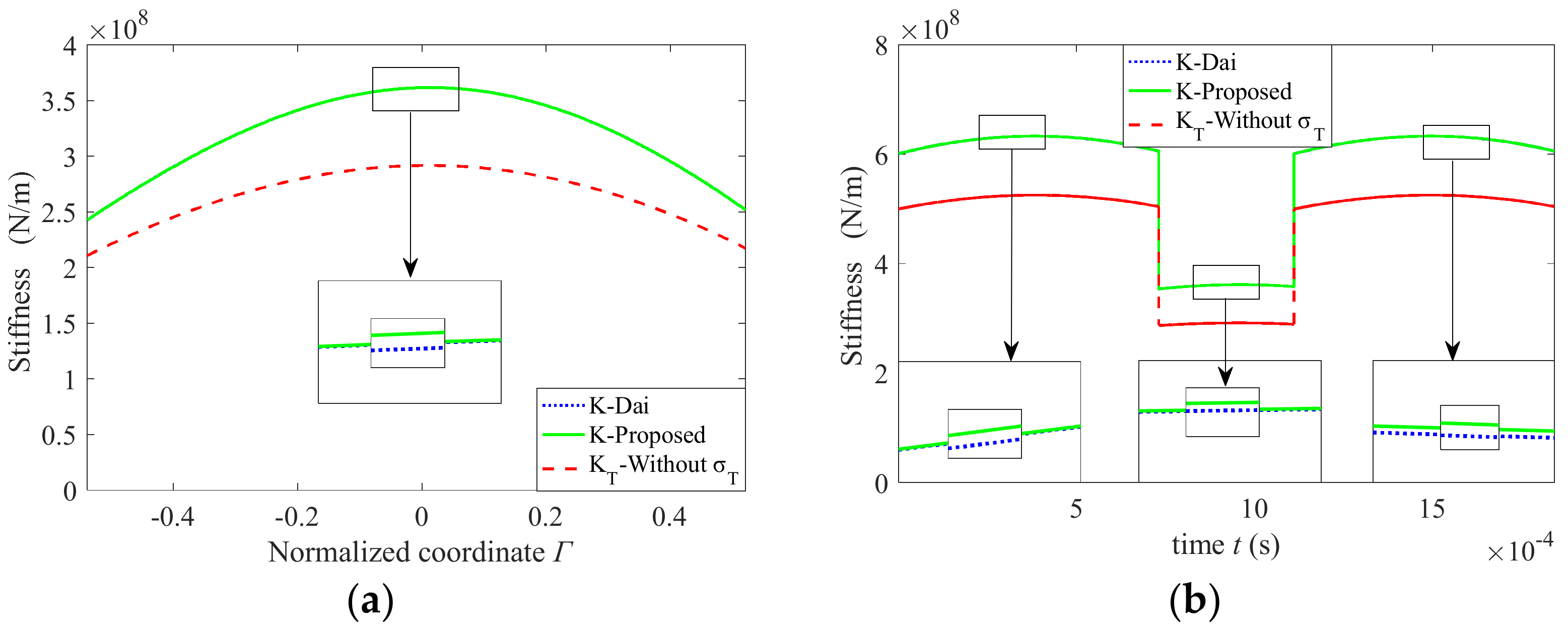
4.1. Influence of the Thermal Stress on Thermal Stiffness

In the case of a linear temperature distribution, the thermal stress obtained by Equation (17) is shown in Figure 6. Figure 6a shows a thermal stress nephogram of the tooth profile plane, and Figure 6b shows the distribution curves of the thermal stress of the pinion and gear at a pitch point along lk.
The thermal stress from the work-side to the back-side is still nonlinear in the case of a linear temperature distribution, as shown in Figure 6. After considering the influence of thermal stress, the distribution curve of the gear thermal mesh stiffness along the line of action and the time-varying thermal mesh stiffness are shown in Figure 7.
Compared with the elastic stiffness, the gear thermal stiffness decreases as a whole after considering the influence of thermal stress, as shown in Figure 7a. Its change trend is consistent with that when the influence of thermal stress is not considered. The decrease is small at the meshing-in and -out points, while the decrease is largest near the pitch point. Compared with the thermal mesh stiffness without considering the thermal stress, the thermal mesh stiffness considering the thermal stress decreases in the area near the pitch point and increases in the meshing-in and -out sections. However, the overall change is small. In this example, the relative increases in the meshing-in and -out points are 0.36% and 0.07%, respectively, and the relative decrease at the pitch point is 0.02%. The effect of thermal stress can be neglected when approximating the gear thermal stiffness. For the time-varying mesh stiffness, the stiffness in the double tooth pair meshing region increases. However, the stiffness in the single tooth pair meshing region decreases after considering the thermal stress. However, the overall change is small.

4.2. Influence of Temperature and Temperature Distribution on Gear Thermal Stiffness

Figure 8 presents the gear thermal stiffness at different temperatures. From Figure 8, the higher the gear temperature rise is, the greater the decrease in the gear stiffness and the smaller the thermal stiffness. In the process of gear transmission, the greater the load is, the higher the temperature rise [22]. Therefore, the greater the load on the gear pair is, the smaller the thermal mesh stiffness. The variation trend of the time-varying mesh stiffness with temperature is consistent with Figure 7a in Reference [24]. This further verifies the correctness of the proposed model in this paper.
In the process of gear meshing, the temperature distribution in the tooth profile plane is very complex. Reference [22] obtained the bulk temperature distribution of the gear by the finite element method. It showed that the temperature distribution in the tooth profile plane had an obvious gradient. However, it did not give the specific temperature distribution function. A steady temperature distribution function was used to study the thermal deformation of gears in Reference [19] (Liu 2020). To study the influence of different temperature distributions on the gear thermal stiffness, the gear thermal stiffness under three different temperature distributions—uniform distribution, linear distribution and the temperature distribution of Liu 2020—are calculated in this paper, as shown in Figure 9.
The distribution of the gear thermal mesh stiffness along the line of action is basically consistent with the changing trend of the time-varying thermal mesh stiffness under different temperature distributions, as shown in Figure 9. Especially under the condition of linear distribution and temperature distribution adopted in the literature [19], the thermal stiffness of gears remains highly consistent in both trend and absolute value. The gear thermal stiffness under uniform distribution has a larger gap than that under the previous two conditions. The study in [22] showed that there is a significant temperature gradient in the body temperature of the gear. The temperature in the tooth profile plane is not uniformly distributed in the actual gear meshing process. Therefore, the influence of the temperature distribution in the tooth profile plane on the gear thermal stiffness is small and can be ignored when approximating the gear thermal stiffness.

5. Verification of Thermal Stiffness

It is difficult to measure the gear thermal stiffness directly by experimental methods because no effective method and relevant published study have been found thus far. According to the calculation formula of the system natural frequency, the natural frequency of system vibration mainly depends on the time-varying mesh stiffness and mass of the system. The mass is independent of temperature [24]. Therefore, the variation trend of the system vibration frequency with temperature can be obtained by Fourier transform of the measured system vibration signals under different temperature conditions. This indirectly verifies the variation trend of the gear stiffness with temperature. The dynamic response of the system and the corresponding temperature in different time periods can be measured by a closed power flow gear testing machine in References [22,23]. The natural frequency of the system vibration can be obtained at different temperatures. The data are shown in Table 3.
According to the data in Table 3, the natural frequency of system vibration decreases with increasing temperature. This means that the time-varying mesh stiffness decreases with increasing temperature because the frequency is proportional to the square root of the stiffness. This result is consistent with the research results of gear thermal stiffness under different temperatures in Section 3.2 and indirectly proves the correctness of the thermal stiffness model proposed in this paper.

6. Conclusions

To study the influence of temperature rise caused by friction heat on gear stiffness, a new analytical model for gear thermal stiffness calculation has been proposed based on the relationship between thermal stress and strain in plane strain theory and the potential energy method for gear stiffness calculation. It deduces the calculation formula for the gear thermal mesh stiffness and time-varying thermal mesh stiffness. The effects of different temperatures, temperature distributions and thermal stresses caused by rising temperature have been investigated on the gear thermal stiffness. The accuracy of the model has been verified by comparative analysis with the data in the literature. The conclusions are summarized as follows:
(1)
The temperature mainly affects the gear stiffness by changing the gear contact stiffness at contact point. Compared with the elastic stiffness, the gear thermal stiffness decreases as a whole. The decrease in stiffness is a nonuniform distribution along the line of action. The decrease is the smallest at the meshing-in and -out points and the largest near the pitch point.
(2)
The thermal stress from the work-side surface to the back-side surface is distributed nonlinearly in the tooth profile plane. The thermal stiffness decreases in the area near the pitch point and increases in the meshing-in and -out sections after considering the thermal stress. Overall, the amount of change is small. The assumption that thermal stress effects are ignored is feasible when calculating the gear thermal stiffness.
(3)
The gear thermal stiffness decreases with increasing gear temperature. The influence of the temperature distribution in the tooth profile plane on the gear thermal stiffness is small. It can be ignored in the approximate calculation of the gear thermal stiffness.

Author Contributions

Writing—Original draft, Y.H.; Writing—Review & editing, H.Y. All authors have read and agreed to the published version of the manuscript.

Funding

This study was funded by the Key-Area Research and Development Program of Guangdong Province (No. 2020B010184001), the Guangdong Innovation and Entrepreneurship Team Introduction Program (No. 2016ZT06G025) and the Natural Science Foundation of Guangdong Province (No. 2017B030306014).

Conflicts of Interest

The authors declare no conflict of interest.

Appendix A

The paper cites Reference [21] as follows:
The decrease is small at the meshing-in and -out points while the decrease is largest near the pitch point. This is consistent with the conclusions in Reference [21]. This effectively proves the correctness of the proposed model. Compared with the method for calculating the gear thermal stiffness by introducing the “thermal stress correction coefficient” in Reference [21], the method proposed in this paper is more general and is a fully analytical method.
The first point of the conclusion in the literature [21] is described as follows:
“In terms of the meshing stiffness, the thermal stiffness is smaller than the elastic stiffness, and their relationship is nonlinear. The difference between thermal stiffness and elastic stiffness is small at the meshing-in and -out points, and the biggest difference emerges near the pitch point.”
The calculation formula of single-tooth thermal stiffness and meshing thermal stiffness in the literature [21] is as follows: (Equations (A1) and (A2) in the literature [21])
k T i = F n k i F n + ( 1 + X te ) k Δ t 1 + Δ t 2 k i Δ t i
k T = k T 1 k T 2 k T 1 + k T 2 = F n k F n + X te k ( Δ t 1 + Δ t 2 )
where Xte is the thermal stress correction coefficient. The method of determining Xte in the literature [21] is as follows:
“The determination of Xte is relatively complex. In this paper, the elastic deformation and the thermo-elastic coupling deformation of the gear at the contact point are obtained by using the finite element method, respectively. Then, the proportional relation between the elastic deformation and the thermo-elastic coupling deformation is obtained. Thus, the thermal stress correction coefficient is ratio of the thermo-elastic coupling deformation and the elastic deformation.”
According to this description, the method for calculating the gear thermal stiffness in Reference [21] is the semi-analytical method.

Appendix B

The paper cites literature [31] as follows:
On the premise that the coupling effect is not considered, and the basic assumption of elasticity is satisfied; the distribution of thermal stress σT along the y-axis is shown in Equation (17) [31].
Part of the second section in the literature [31] reads as follows:
Thermal deformation analysis of the foundation circle of the star wheel.
To discuss the thermal deformation of the star wheel, the relationship between temperature change and stress and displacement needs to be established. The physical equation of the base circle is
ε r α l t r = 1 E σ r μ σ θ + σ z ε θ α l t r = 1 E σ θ μ σ r + σ z ε z α l t r = 1 E σ z μ σ r + σ θ
where αl denotes the linear expansion coefficient of the object; μ denotes Poisson’s ratio; E is Young’s modulus; ε r , ε θ and ε z are the strains in the three coordinate directions under the cylindrical coordinate system; σ r , σ θ and σ z are the stresses in the three coordinate directions under the cylindrical coordinate system; t(r) is the temperature distribution function.
Without considering the axial variation of the star wheel, the plane strain model is used, i.e., ε z = 0 , σ z = μ ( σ r + σ θ ) α l E t ( r ) . Thus, Equation (A3) can be expressed as
ε r = 1 μ 2 E σ r μ 1 μ σ θ + 1 + μ α l t r ε θ = 1 μ 2 E σ θ μ 1 μ σ r + 1 + μ α l t r
Combining geometric equations εr = du/dr, εθ = u/r and equilibrium differential equations d σ r / d r + σ r σ θ / d r = 0 , the displacement and stress equations can be expressed as
u = 1 + μ 1 μ α l r a r t ( r ) r d r + C 1 r + C 2 r σ r = α l E 1 μ 1 r 2 a r t ( r ) r d r + E 1 + μ C 1 1 2 μ C 2 r 2
According to the above description, σ r is the thermal stress, that is the σ T in this paper. The difference between Equation (A5) in the literature [31] and Equation (17) in this paper is the integral interval is changed to (0, lk). In addition, there is also a variable substitution, i.e., r = ρ k y , because the origin of the coordinate is the contact point rather than the center of the circle in this paper, as shown in Figure 3.

References

  1. Liang, X.; Zhang, H.; Zuo, M.J.; Qin, Y. Three new models for evaluation of standard involute spur gear mesh stiffness. Mech. Syst. Sig. Process. 2018, 101, 424–434. [Google Scholar] [CrossRef]
  2. Tang, X.; Zou, L.; Yang, W.; Huang, Y.; Wang, H. Novel mathematical modelling methods of comprehensive mesh stiffness for spur and helical gears. Appl. Math. Model. 2018, 64, 524–540. [Google Scholar] [CrossRef]
  3. Feng, M.; Ma, H.; Li, Z.; Wang, Q.; Wen, B. An improved analytical method for calculating time-varying mesh stiffness of helical gears. Meccanica 2018, 53, 1131–1145. [Google Scholar] [CrossRef]
  4. Yang, Y.; Wang, J.; Zhou, Q.; Huang, Y.; Zhu, J.; Yang, W. Mesh stiffness modeling considering actual tooth profile geometry for a spur gear pair. Mech. Ind. 2018, 19, 306. [Google Scholar] [CrossRef] [Green Version]
  5. Feng, S.; Chang, L.; He, Z. A hybrid finite element and analytical model for determining the mesh stiffness of internal gear pairs. J. Mech. Sci. Technol. 2020, 34, 2477–2485. [Google Scholar] [CrossRef]
  6. Wang, Q.; Chen, K.; Zhao, B.; Ma, H.; Kong, X. An analytical-finite-element method for calculating mesh stiffness of spur gear pairs with complicated foundation and crack. Eng. Fail. Anal. 2018, 94, 339–353. [Google Scholar] [CrossRef]
  7. Verma, J.G.; Kumar, S.; Kankar, P.K. Crack growth modeling in spur gear tooth and its effect on mesh stiffness using extended finite element method. Eng. Fail. Anal. 2018, 94, 109–120. [Google Scholar] [CrossRef]
  8. Cooley, C.G.; Liu, C.; Dai, X.; Parker, R.G. Gear tooth mesh stiffness: A comparison of calculation approaches. Mech. Mach. Theory 2016, 105, 540–553. [Google Scholar] [CrossRef] [Green Version]
  9. Karpat, F.; Yuce, C.; Dugan, O. Experimental measurement and numerical validation of single tooth stiffness for involute spur gears. Measurement 2020, 150, 107043. [Google Scholar] [CrossRef]
  10. Raghuwanshi, N.K.; Parey, A. Experimental measurement of mesh stiffness by laser displacement sensor technique. Measurement 2018, 128, 63–70. [Google Scholar] [CrossRef]
  11. Chen, K.; Huangfu, Y.; Ma, H.; Xu, Z.; Li, X.; Wen, B. Calculation of mesh stiffness of spur gears considering complex foundation types and crack propagation paths. Mech. Syst. Sig. Process. 2019, 130, 273–292. [Google Scholar] [CrossRef]
  12. Jiang, H.J.; Liu, F.H. Mesh stiffness modelling and dynamic simulation of helical gears with tooth crack propagation. Meccanica 2020, 55, 1215–1236. [Google Scholar] [CrossRef]
  13. Wang, Q.B.; Zhang, Y.M. A model for analyzing stiffness and stress in a helical gear pair with tooth profile errors. J. Vib. Control 2017, 23, 272–289. [Google Scholar] [CrossRef]
  14. Saxena, A.; Parey, A.; Chouksey, M. Time varying mesh stiffness calculation of spur gear pair considering sliding friction and spalling defects. Eng. Fail. Anal. 2016, 70, 200–211. [Google Scholar] [CrossRef]
  15. Cui, L.; Liu, T.; Huang, J.; Wang, H. Improvement on Meshing Stiffness Algorithms of Gear with Peeling. Symmetry 2019, 11, 609. [Google Scholar] [CrossRef] [Green Version]
  16. Chen, Z.G.; Shao, Y.M. Mesh stiffness calculation of a spur gear pair with tooth profile modification and tooth root crack. Mech. Mach. Theory 2013, 62, 63–74. [Google Scholar] [CrossRef]
  17. Gou, X.F.; Qi, C.J.; Chen, D.L. Nonlinear dynamic modelling and analysis of gear system with tooth contact temperature. J. Mech. Eng. 2015, 51, 71–77. (In Chinese) [Google Scholar] [CrossRef]
  18. Lin, T.; Zhao, Z.; Jiang, F.; Chen, B. An analytic algorithm of time-varying mesh stiffness of helical gears considering temperature effect. J. Hunan Univ. (Nat. Sci.) 2020, 47, 6–13. (In Chinese) [Google Scholar]
  19. Liu, H.; Yan, P.F.; Gao, P. Effects of temperature on the time-varying mesh stiffness, vibration response, and support force of a multi-stage planetary gear. J. Vib. Acoust. 2020, 142, 051110. [Google Scholar] [CrossRef]
  20. Sun, Z.; Chen, S.; Hu, Z.; Tao, X.; Chen, Y. Analytical models for thermal deformation and mesh stiffness of spur gears under steady temperature field. Eng. Fail. Anal. 2022, 133, 105972. [Google Scholar] [CrossRef]
  21. Luo, B.; Li, W.; Li, L.S. Research on thermal stiffness of gear based on thermo-elastic coupling. J. Cent. South Univ. (Sci. Technol.) 2017, 48, 3209–3215. (In Chinese) [Google Scholar]
  22. Luo, B.; Li, W. Investigation on the influence of heat on the dynamic characteristics of a gear transmission system. Eng. Fail. Anal. 2020, 116, 104724. [Google Scholar] [CrossRef]
  23. Luo, B.; Li, W. Experimental study on thermal dynamic characteristics of gear transmission system. Measurement 2019, 136, 154–162. [Google Scholar] [CrossRef]
  24. Lu, R.X.; Tang, W.C. Analytical calculation models for mesh stiffness and backlash of spur gears under temperature effects. Proc. Inst. Mech. Eng. Part C J. Mech. Eng. Sci. 2022, 236, 4450–4462. [Google Scholar] [CrossRef]
  25. Dai, H.; Long, X.; Chen, F.; Xun, C. An improved analytical model for gear mesh stiffness calculation. Mech. Mach. Theory 2021, 159, 104262. [Google Scholar] [CrossRef]
  26. Liang, X.; Zuo, M.J.; Patel, T.H. Evaluating the time-varying mesh stiffness of a planetary gear set using the potential energy method. Proc. Inst. Mech. Eng. Part C J. Mech. Eng. Sci. 2013, 228, 535–547. [Google Scholar] [CrossRef]
  27. Sainsot, P.; Velex, P.; Duverger, O. Contribution of gear body to tooth deflections—A new bidimensional analytical formula. J. Mech. Des. 2004, 126, 748–752. [Google Scholar] [CrossRef]
  28. Xie, C.; Hua, L.; Han, X.; Lan, J.; Wan, X.; Xiong, X. Analytical formulas for gear body-induced tooth deflections of spur gears considering structure coupling effect. Int. J. Mech. Sci. 2018, 148, 174–190. [Google Scholar] [CrossRef]
  29. Luo, B.; Li, W. Influence factors on bulk temperature field of gear. Proc. Inst. Mech. Eng. Part J J. Eng. Tribol. 2017, 231, 953–964. [Google Scholar] [CrossRef]
  30. Johnson, K.L. Contact Mechanics; Cambridge University Press: Cambridge, MA, USA, 1985. [Google Scholar]
  31. Ren, S.B.; Bai, M.H. Hot deformation and error analysis of sprocket wheel tooth profile for even tooth sintering machine. Chin. J. Mech. Eng. 2011, 47, 55–60. (In Chinese) [Google Scholar] [CrossRef]
Figure 1. The flow chart to summarize the proposed model.
Applsci 13 03599 g001
Figure 2. The gear tooth profile model. (a) Load on the tooth; (b) Geometric model of lk.
Applsci 13 03599 g002
Figure 3. Tooth surface contact model.
Applsci 13 03599 g003
Figure 4. Normalized coordinates of the line of action. A—the meshing-in point; C—the pitch point; E—the meshing-out point; K—arbitrary contact point on the line of action; N1—ideal meshing-in point; N2—ideal meshing-out point; r1—pitch radius of the pinion; r2—pitch radius of the gear; ra1—radius of addendum of the pinion; ra2—radius of addendum of the gear; rb1—base radius of the pinion; rb2—base radius of the gear.
Applsci 13 03599 g004
Figure 5. Gear thermal stiffness without considering thermal stress. (a) Mesh stiffness of a single pair of teeth; (b) Time-varying mesh stiffness of gears.
Applsci 13 03599 g005
Figure 6. Thermal stress in the tooth profile plane: (a) thermal stress nephogram of the tooth profile plane; (b) distribution curves of thermal stress of pinion and gear at pitch point along lk.
Applsci 13 03599 g006
Figure 7. Gear thermal stiffness: (a) thermal mesh stiffness of a single tooth pair; (b) time-varying thermal mesh stiffness.
Applsci 13 03599 g007
Figure 8. Gear thermal stiffness at different temperatures. (a) Thermal mesh stiffness of a single tooth pair; (b) Time-varying gear thermal mesh stiffness.
Applsci 13 03599 g008
Figure 9. Gear thermal stiffness under different temperature distributions: (a) thermal mesh stiffness of a single tooth pair; (b) time-varying gear thermal mesh stiffness [19].
Applsci 13 03599 g009
Table 1. Material properties of carbon steel at different temperatures [20].
Room temperature (°C)2575125175225
Young’s modulus (GPa)207204200195189
Poisson’s ratio0.2900.2920.2940.2960.298
Table 2. Parameters of the spur gear pair.
Number of Teeth z1/z2Module m (mm)Pressure Angle α (°)The Face Width b (mm)Power P (kW)Speed n1 (r·min−1)
27/3532025802000
Addendum coefficient h a Clearance coefficient c*Linear expansion coefficient αT (°C−1)Gear initial temperature (°C)Steady-state temperature rise of mesh tooth surface (°C)Steady-state temperature rise of nonmesh tooth surface (°C)
10.21.13 × 10−52060, 75, 9050, 60, 70
Table 3. Vibration frequency data of the gear system at different temperatures [23].
MomentThe 2nd minThe 4th minThe 6th minThe 8th minThe 10th min
Temperature (°C)31.433.236.839.142.7
Frequency (Hz)350.2348.8347.8347.6347.3
Disclaimer/Publisher’s Note: The statements, opinions and data contained in all publications are solely those of the individual author(s) and contributor(s) and not of MDPI and/or the editor(s). MDPI and/or the editor(s) disclaim responsibility for any injury to people or property resulting from any ideas, methods, instructions or products referred to in the content.

