Abstract
Aiming at the approach and landing of an aircraft under low visibility, this paper studies the use of an infrared heat-transfer imaging camera and visible-light camera to obtain dynamic hyperspectral images of flight approach scenes from the perspective of enhancing pilot vision. Aiming at the problems of affine deformation, difficulty in extracting similar geometric features, thermal shadows, light shadows, and other issues in heterogenous infrared and visible-light image registration, a multi-modal image registration method based on RoI driving in a virtual scene, RoI feature extraction, and virtual-reality-fusion-based contour angle orientation is proposed, and this could reduce the area to be registered, reduces the amount of computation, and improves the real-time registration accuracy. Aiming at the differences in multi-modal image fusion in terms of resolution, contrast, color channel, color information strength, and other aspects, the contour angle orientation maintains the geometric deformation of multi-source images well, and the virtual reality fusion technology effectively deletes incorrectly matched point pairs. By integrating redundant information and complementary information from multi-modal images, the visual perception abilities of pilots during the approach process are enhanced as a whole.
1. Introduction
The approach and landing phases of an aircraft are important parts of their safe flight [1,2,3]. In most cases, visual observation by the pilot in command is used for landing, so this is a great potential safety hazard. This phase is also an important phase for flight accidents. If we can provide captains with timely information on the flight situation and scenes outside the window during approaching and landing, to enhance captains’ vision. Meanwhile, we can help them to correctly perceive and operate, as well as greatly reduce the incidence of flight accidents in the aircraft approach and landing phases.
The fusion of multi-modal images, such as infrared images and visible-light images, can provide more visual information for the captain. The premise of image fusion is to correctly realize image registration. Traditional feature extraction algorithms, such as the SIFT (Scale-Invariant Feature Transform) [4,5,6], SURF (Speeded-Up Robust Feature) [7,8,9], ORB (Oriented FAST and Rotated Brief) [10,11], and FAST (Features from Accelerated Segment Test) [12,13] operators, are not prominent for visible images under low-visibility conditions due to the blurring of edges and detailed information. Zeng et al. [14] proposed a method that used a morphological gradient and C_ SIFT, which was a new algorithm for real-time adaptive registration of visible-light and infrared images. The algorithm could quickly complete the registration of visible-light and infrared images, and the registration accuracy was satisfactory. Ye et al. [15] proposed a novel keypoint detector to extract corners and spots at the same time. The proposed detector was named Harris–Difference of Gaussian (DoG), and it combined the advantages of the Harris–Laplace corner detector and DoG blob detector. The experimental results showed that Harris–DoG could effectively increase the number of correct matches and improve the registration accuracy compared with the most advanced keypoint detector. Cui et al. [16] proposed a multi-modal remote sensing image registration method that had scale, radiation, and rotation invariance. These studies integrated several methods of feature extraction to achieve better performance than that obtained with the extraction of a single feature. It was found in a large number of experiments that for infrared and visible-light images with low visibility, the aforementioned features do not describe the image pairs to be registered well.
With the popularity of deep learning and neural networks, scholars have begun to focus on multi-modal image registration based on neural networks [17,18,19,20,21]. Arar et al. [22] achieved the registration of multi-modal images through a space conversion network and translation network. They trained the translation network from image to image on two input modes, bypassing the difficulty of developing a cross-mode similarity measurement. Xu et al. [23] proposed an RFNet network structure to achieve multi-modal image registration and fusion in the framework of mutual enhancement, and this processed registration from coarse to fine. This method used the feedback of image fusion to improve the registration accuracy for the first time, instead of treating these as two independent problems. Fine registration also improved the fusion performance. Song et al. [24] proposed a depth feature correlation learning network (Cnet) for multi-modal remote sensing image registration to solve the problem of the existing depth learning descriptor not being suitable for multi-modal remote sensing image registration. In view of the differences between infrared and visible-light images in terms of resolution, spectrum, angle of view, etc., deep learning was used to integrate image registration, image fusion, and semantic requirements into a framework, and an automatic registration algorithm that corrected the geometric distortion in the input image under the supervision of photometric and endpoint constraints was proposed [25,26,27]. A method based on neural networks needs large numbers of image samples. For application scenarios with low-visibility aerial images, such methods have certain limitations.
Low visibility is the main reason for flight accidents during approach and landing, so virtual reality has come into being. In order to solve this problem, the current global technical means mainly include heads-up guidance systems, enhanced visual systems (EVSs), and synthetic visual systems (SVSs) [28,29]. Among these, EVSs and SVSs are designed to provide pilots with enhanced views of the ground and air conditions by using advanced infrared thermal imaging and visible-light sensors, as well as cockpit displays. As the two most important photoelectric sensors, infrared thermal imaging and visible-light imaging sensors have different imaging mechanisms and application scenarios, and the information that they obtain is naturally complementary. Infrared thermal imaging obtains a target’s temperature radiation intensity information, while visible-light imaging reflects the target’s texture and contour information. By integrating infrared information and visible-light information into one image, we can achieve feature information complementation and reduce redundant information [30,31,32,33], which has an important value and significance in the field of low-visibility monitoring.
Jiang et al. [34] proposed a new main direction for feature points, which is called the contour angle direction (CAO), and they described an automatic infrared and visible-light image registration method called CAO–Coarse to Fine (CAO-C2F). CAO is based on the contour features of an image, and it is invariant to the image’s viewpoint and scale differences. C2F is a feature-matching method for obtaining correct matching. Repeated experiments showed that the method could accurately propose feature points in low-visibility visible-light images, and the feature points had good geometric invariance, which is conducive to the accurate registration of infrared and visible-light images. However, contour extraction is the key to the algorithm. The canny edge detection algorithm was used to extract contours in the literature. Fixed high and low thresholds are very poorly adaptive for low-visibility aerial images. The selection of an automatic threshold depends on the proportion of image edge pixels in an image. The method based on virtual reality proposed in this paper can give an a priori proportion.
The main contributions of our paper are:
- (1)
- A virtual reality-based automatic threshold for Canny edge detection is proposed. According to the prior knowledge of the virtual image, the high and low threshold of Canny edge detection is automatically determined.
- (2)
- A registration method for extracting low visibility multi-modal aerial images based on virtual reality is proposed. The virtual image provides the matching region of interest, and gives the approximate position of the matching points of the image to be registered, so as to eliminate the wrong matching point pairs.
2. Real Scene Acquisition and Generation of Virtual Scene Simulation
2.1. Real Scene Imaging Analysis Based on Infrared Visible Binocular Vision
For data acquisition of airborne multi-mode photoelectric sensor, the sensor position would be set near or parallel to the central axis of the aircraft as far as possible, such as the belly or just below the wing, so that the attitude data of the aircraft inertial navigation system, such as heading, pitch, roll, can also truly reflect the current state of the image sensor at the same time, and the two ones would be consistent as far as possible. At the same time, consider the installation space of the two types of photoelectric sensor equipment, and try to make the infrared thermal imaging and visible image imaging have the same field of vision. When installing the two types of photoelectric camera equipment, adopt the binocular vision mode of side-by-side installation, as shown in Figure 1.
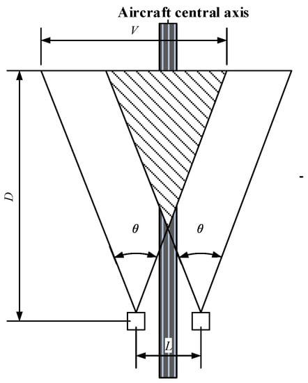
Figure 1.
Installation diagram of the binocular sensor.
The coordinate system is established based on the optical axis of the camera and the relative displacement of the camera. The distance between cameras is L, and the distance between the optical center of the camera and the farthest monitored target is D. Then the effective field of view of each camera is expressed as V:
where is angle of view.
For each camera, the ratio of its field of view overlapping range to its overall field of view is:
Since the is a fixed value when , the above equation is about 1, it can be considered that the two cameras have the same field of view. However, in practice, assuming , we can make it possible to obtain the equivalent closest distance between two cameras. For example, if two cameras with a viewing angle of 60 degrees and a distance of 2 m are required to have at least 95% the same field of vision, then meters can be obtained, that is , the observation target must be beyond this distance, otherwise, the images of the two cameras cannot be equivalent to similar fields of vision.
If the installation positions of the two cameras are very close, from the perspective of scene imaging, it can be considered that the optical centers of the two cameras coincide, but the optical axes of the cameras do not overlap, so there is a certain angle difference. In this case, the difference between the two cameras can be described by affine transformation or an 8-parameter homography transformation matrix. The camera lens can perform translation, pan, tilt, rotation, zoom and other actions without restrictions. The 8-parameter homography projection transformation model can describe the camera’s translation, horizontal scanning, vertical scanning, rotation, lens scaling and other movements, and the projection transformation can reflect the trapezoidal distortion during imaging, while the translation, rotation, rigid body and affine transformation can be regarded as special cases of projection transformation. Therefore, in most cases, the projection transformation model is used to describe the camera’s movement or the coordinate transformation relationship between cameras in general motion. The projection transformation process of the camera model can be described by the following formula:
where in the homogeneous coordinate system, is the world point coordinate, and is the pixel coordinate. , represent the actual size of the pixel on the photosensitive chip, and , are the center of the image plane. R is a rotation matrix with the size of , which determines the orientation of the camera. t is a translation vector with the size of , which determines the position of the camera.
is the image coordinate before transformation, and is the image coordinate after transformation. The expression of homography transformation is expressed by homogeneous coordinates as follows:
Equivalently,
where , , , are scaling and rotation factor; , are translation factors in horizontal and vertical directions, respectively, and , are affine transformation factors.
2.2. Virtual Scene Simulation Based on OSG Imaging
OSG (Open Scene Graph) is a cross-platform open-source scene graphics programming interface (API), which plays an important role in 3D applications. The visual simulation based on OSG can change the digital information in the simulation process into an intuitive, graphical and image representation, and present the simulation process changing with time and space to the observer. Based on the static data and real-time flight parameter data including airport database and terrain database, this paper generates a virtual scene, shown in Figure 2.
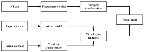
Figure 2.
Workflow of virtual scene generation simulation platform.
In this paper, the flight parameters are obtained by the attitude and azimuth integrated navigation system. The traditional inertial navigation system has the advantages of being independent of external information, good concealment, strong anti-interference and all-weather operation. It is a completely autonomous navigation system that can provide multiple navigation parameters. However, its accuracy varies with time, and large errors will be accumulated during long-time operation, which makes the inertial navigation system unsuitable for long-time navigation. GPS has high navigation accuracy, but due to the mobile change of the moving carrier, it is often difficult for the receiver to capture and track the satellite carrier signal, or even lose the lock on the tracked signal. In order to give full play to the advantages of the two technologies, improve the product performance more effectively and comprehensively, and enhance the reliability, availability and dynamics of the system, this project adopts an attitude and azimuth integrated navigation system that combines satellite positioning and inertial measurement.
Because the low refresh rate of flight parameter data cannot match the frame rate of visual stimulation, sometimes there is an error or jitter. Through experiments, it is found that, especially when the aircraft turns, roll, pitch and other parameters will produce some jitter errors. Therefore, the flight parameter data should be smoothed and interpolated. Assuming that the flight path falls on a smooth surface of degree p in a short time, and let the surface equation be
where is an undetermined coefficient, with items in total. Select observation data , sort the subscripts of the coefficients to be determined according to the dictionary, the coefficient to be determined is changed to (in order to prevent the introduction of too many subscripts, it is still represented by subscript i), and the linear equations are obtained:
where
According to the definition of the generalized inverse matrix, it is the least square solution of equation group . For missing or abnormal flight data such as altitude, it can be fitted according to the following formula:
The visual analysis of two takeoff and landing aircraft attitude data after preprocessing is shown in Figure 3, in which longitude, latitude and height data are smooth.
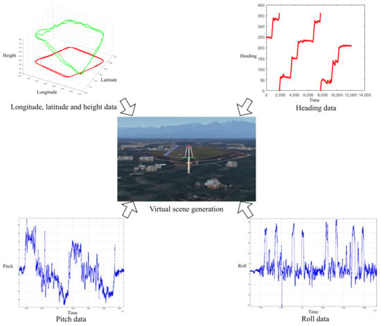
Figure 3.
Visual analysis of flight data and virtual scene generation framework.
3. Multi-Modal Image Registration Based on Virtual Scene ROI Drive
Image registration is the process of superimposing two or more images in different times, spaces and modes, which is shown as finding the best geometric transformation relationship between different images. Suppose is the reference image and is the registration image to seek the transformation between them. The mathematics can be defined as:
represents image coordinates, represents geometric transformation, and represents grayscale transformation.
According to the different image information used in the registration process, the registration methods are mainly divided into the region (pixel) based registration and feature-based registration [7]. The region (pixel) based registration technology is to use the global or local gray-level information of the image for registration. The advantage is that it is simple to implement and does not need to extract image features. The disadvantage is that the gray information of the whole image is involved in the calculation, which requires a large amount of calculation and high implementation complexity. Region (pixel) based registration technology can be roughly divided into three categories: cross-correlation method, mutual information method and transform domain method [7]. Feature-based registration technology aims to extract some distinctive features of the image, use the corresponding relationship between features to match features, and then obtain the spatial transformation of the image to be registered. Features mainly include point features, line features and area features. Because the number of features in the image is far less than the number of pixels in the image, the amount of calculation is greatly reduced.
In the aircraft approach phase, the airborne infrared convertible optical camera platform system is generally prone to cause differences in translation, rotation, scaling and shearing between two images due to aircraft jitter, weather, shooting angle and other factors. Therefore, real-time and high-precision registration is a necessary prerequisite for the fusion of airborne approach images. This paper proposes the generation of airport ROI region based on virtual scene driving and realizes the registration based on ROI feature extraction and RANSAC (Random Sample Consensus), which can greatly reduce the amount of computation, improve the relevance of the images to be registered, and further improve the real-time registration accuracy.
3.1. ROI Region Generation Based on Virtual Scene Driving
Since we know the location of the airport surface area in the virtual scene, we consider that the key object in the approach phase is the airport area, especially the runway, taxiway and other areas, and the image registration and fusion effect of the above airport area is the key object in the air approach. Therefore, in order to reduce the impact of other imaging areas on the airport area registration, this paper is based on the flight parameter drive OSG virtual scene simulation. Before the simulation, adjust the resolution, imaging depth and other relevant parameters of the virtual scene to be roughly consistent with the imaging distribution of the photoelectric equipment scene.
Assume the coordinates of a point P in a 3D scene. The camera position error caused by the relative relationship between the object point and the camera and the GPS error is equivalent to the offset of the space point in the 3D model. Combined with camera attitude error caused by AHRS, the position of the point P in the camera coordinate system is
Henceforth the approximate expression of the vertex deviation of virtual and real runways is obtained from (11), and (12):
where , and is related to position accuracy.
In different approach and landing phases, different areas are selected as ROI. During the phase far away from the runway, the area outside the runway, such as roads, fields, buildings and other dense areas, is selected as ROI, as effective feature points cannot be extracted from the blurred runway in the visible image. For the phase approaching the runway, the runway and adjacent areas are selected as ROI. According to the above selection criterion, more features can be extracted in the region of interest for matching, as shown in Figure 4, and the area below the dotted line is selected as ROI. The main purpose of this ROI is to reduce the amount of registration calculation, narrow the registration range and improve the registration accuracy.

Figure 4.
ROI region generation based on flight parameters.
3.2. Curvature Based Registration Method
The imaging principles of infrared images and visible images are different. Common feature extraction algorithms such as SIFT, SURF, ORB, FAST, etc, often behave poorly on the registration of multi-modal images. For multi-modal images, the key to feature extraction is to keep geometric features invariant. The feature extraction method based on image curvature [34] is adopted in this paper.
3.2.1. Automatic Threshold Canny Edge Detection Based on Virtual and Real Fusion
Literature [34] proposes a curvature-based registration method for infrared and visible images, which effectively solves the problem of heterogeneous image matching with the help of geometric deformation. The registration algorithm first detects the edge of the image according to the Canny algorithm, then tracks the contour, calculates the curvature of the contour points, and considers that the position of the local minimum curvature is the feature point. Subsequently, the high-dimensional feature description vector is obtained by imitating the feature descriptor of SIFT, so as to realize the registration of multi-modal images.
In Canny edge detection, the determination of automatic threshold is based on an important parameter, that is the proportion of pixels in an image that are not edges to the image, denoted by . This parameter needs to be given by the prior experience of the image. Generally, it is estimated that . In this paper, according to the virtual image of the scene, the can be roughly estimated, so that Canny edge detection with an automatic threshold can be realized. The specific steps are as follows:
- (1)
- Smooth image using Gaussian filtering:where is the grayscale intensity image converted from the truecolor image, scaled the display based on the range of pixel values, “∗” denotes the convolution operation and is the surround function:where is the Gaussian surround space constant, and is selected such that:
- (2)
- Calculate gradients using a derivative of the Gaussian filter:Compute smoothed numerical gradient of the image I along x, y direction, denoted by , , respectively.
- (3)
- Compute the magnitude of gradient:
- (4)
- Create a histogram with N bins for the magnitude M:Initialize: , , …, N.Traverse: , where , , , , for each x, y, i.
- (5)
- Find the smallest h that meets the condition:
- (6)
- Select h as the optimal high threshold, as the optimal small threshold, where r is pre-defined proportional value.
3.2.2. Infrared and Visible Image Registration Based on Contour Angle Orientation and Virtual Reality Fusion
Inspired by CAO, this paper proposes an improved CAO algorithm based on virtual and real fusion. According to the region of interest determined by Section 3.1, first, calculate the automatic threshold of the Canny edge detection operator, then track the contour, and compute the curvature of the contour points, and finally determine the feature points. Due to the visible image under low visibility considered in this paper, the edge blur affects the accuracy of matching to some extent, which is easy to lead to wrong matching point pairs. The virtual image proposed in this paper can be used as effective reference information for matching. Equation (13) gives the approximate corresponding position of the infrared image feature points in the visible image, thus realizing the process from rough matching to fine matching.
4. Experimental Analysis
The effect of infrared thermal imaging image sequence, visible image sequence and image sequence after registration fusion collected during the experiment is shown in Figure 5. It is worth noting that the parameters used in the experimental results are .

Figure 5.
Multi source image registration and fusion effect at different stages of approach and landing.
The single-step execution result is shown in Figure 6. In the first row, they are infrared and visible source images, respectively. It is not difficult to see that the visible image is affected by low visibility and the details are blurred, which brings difficulties to image matching. Therefore, as shown in Figure 6c,d, more curvature corners are extracted from infrared images than visible images. For contour corners, the histogram of gradient amplitude in the range of 0 to 180 degrees is calculated by analogy with the traditional SIFT operator, and a 128-dimension feature descriptor is generated to realize rough matching. In coarse matching (see Figure 6e), error matching often occurs in the sky area of the infrared image. In fine matching, 16 pairs of point-to-point matching are randomly selected, as shown in Figure 6f, and there is no matching error.
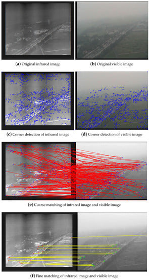
Figure 6.
The single-step execution result.
Registration Quality Evaluation
We used two registration quality measurements(RQM) to assess the accuracy of registration, namely subjective and objective RQM. In subjective evaluation, pixel average fusion and checkerboard presentation are adopted. In the checkerboard presentation, the infrared image and the registered visible image are segmented in the same way, and either of them is spliced into an image at the same location, as shown in Figure 7b. The fusion result based on the average pixel value of the infrared image and visible image is shown in Figure 7. In order to more intuitively explain the accuracy of registration, in the checkerboard fusion results, the segmented areas of roads and fields in the infrared image are completely collinear with the adjacent visible image, and the registration results are consistent with the naked eye judgment.
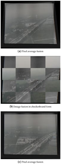
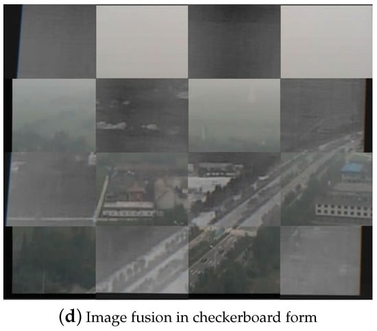
Figure 7.
Image fusion of two presentation formats.
The subjective evaluation of the fused image quality depends on the human visual perception system, focusing on image details, contrast, definition and other spectral characteristics, but the image quality is also affected by other aspects except for spectral characteristics. The human visual perception system is not sensitive to these aspects, so the subjective evaluation is not comprehensive. Therefore, researchers have proposed some objective evaluation methods that can be measured quantitatively based on information theory, structural similarity, image gradient and statistics. The following three quality evaluation indicators are mainly used to evaluate the quality of fused images in this paper:
- (1)
- Root Mean Square Error: Because the real transformation parameters between images are not known, the root mean square error between the matching point pairs involved in the transformation model calculation in image registration is used as the registration accuracy index.where M is the transformation matrix between image and , and are the coordinates of matching point pairs in the overlapping area of adjacent images, and m is the number of matching point pairs in the overlapping area. By randomly extracting 10 frames of synchronous data from the video, is calculated and analyzed, and the geometric error of registration accuracy is within 1 pixel.
- (2)
- Entropy: Entropy is an indicator used to represent the amount of information in information theory, which can be used to measure the amount of information in fused images. The mathematical definition of entropy is as follows:In (19), the L represents the number of gray levels, the is the normalized histogram of corresponding gray levels in the fusion image and represents the probability density of each gray level pixel.
- (3)
- Edge information: It mainly calculates how much information is transferred from the source image to the fused image. The mathematical definition of mutual information is as follows: According to the word number of edge information transfer () proposed by Xydeas and Petrovic in [12], measure the amount of edge information transferred from the source image to the fused image. The mathematical definition is as follows:
where and , respectively, represent the intensity and direction of the edge at , and represent the weight of the source image to the fused image.
Table 1 lists the comparison results of fusion image quality between the method in this paper and the method proposed by Oliver R in the literature [35]. It can be seen from the table that the quality index of the fusion image obtained by this method has good performance.

Table 1.
Fusion image quality comparison.
5. Conclusions
The registration and fusion of low-visibility aerial surveillance images have always been a hot issue in academia and industry, with a wide range of application scenarios. The experimental results show that the method proposed in this paper is accurate and stable in extracting the features of the image to be registered, with a high effective matching ratio and good robustness in multi-scale changing scenes. Compared with the individual visible light and infrared thermal imaging images, the registered fusion image contains a large amount of information, and the runway and other target images have obvious contrast with the background image, which greatly improves the approach visibility under low visibility. In the later stage, GPU CUDA will be used to further accelerate the optimization of real-time registration and fusion. The research on virtual scene generation, virtual reality registration fusion, and infrared and visible light image registration fusion carried out in this paper is one of the key theories and technologies to be solved by the approach landing system under low visibility. The research results verify the feasibility of the method proposed in this paper for enhancing the scene of low visibility approach flight and also have important social and economic significance for ensuring aviation safety and reducing accident losses.
Author Contributions
Conceptualization, Y.W. and C.L.; Methodology, Y.W.; Software, C.L.; Validation, Y.W. and C.L.; Formal Analysis, Y.W.; Investigation, C.L.; Resources, Y.W.; Data Curation, C.L.; Writing—Original Draft Preparation, Y.W.; Writing—Review & Editing, C.L.; Visualization, Y.W.; Supervision, C.L.; Project Administration, Y.W.; Funding Acquisition, Y.W. All authors have read and agreed to the published version of the manuscript.
Funding
This research was funded by National Key R&D Program of China grant number 2021YFF0603904 and the Fundamental Research Funds for the Central Universities grant number ZJ2022-004.
Institutional Review Board Statement
Not applicable.
Informed Consent Statement
Not applicable.
Data Availability Statement
Not applicable.
Acknowledgments
This work was also supported in part by the Open Project of the Key Lab of Enterprise Informationization and Internet of Things of Sichuan Province grant number 2022WZJ01, Graduate innovation fund of Sichuan University of Science and Engineering grant number Y2021099, and Postgraduate course construction project of Sichuan University of Science and Engineering grant number YZ202103. The authors would like to thank all the funding agencies for their financial support of this work.
Conflicts of Interest
The authors declare no conflict of interest.
References
- Zanin, M. Assessing Airport Landing Efficiency Through Large-Scale Flight Data Analysis. IEEE Access 2020, 8, 170519–170528. [Google Scholar] [CrossRef]
- Sripad, S.; Bills, A.; Viswanathan, V. A review of safety considerations for batteries in aircraft with electric propulsion. MRS Bull. 2021, 46, 435–442. [Google Scholar] [CrossRef]
- Kawamura, E.; Dolph, C.; Kannan, K.; Lombaerts, T.; Ippolito, C.A. Simulated Vision-based Approach and Landing System for Advanced Air Mobility. In Proceedings of the AIAA SciTech 2023 Forum, National Harbor, MD, USA, 23–27 January 2023; p. 2195. [Google Scholar]
- Lowe, D. Object recognition from local scale-invariant features. In Proceedings of the IEEE International Conference on Computer Vision, Kerkyra, Greece, 20–27 September 1999. [Google Scholar]
- Lowe, D. Distinctive Image Features from Scale-Invariant Key-points. Int. J. Comput. Vis. 2004, 60, 91–110. [Google Scholar] [CrossRef]
- Qian, Y. Research on Painting Image Classification Based on Transfer Learning and Feature Fusion. Math. Probl. Eng. 2022, 2022, 5254823. [Google Scholar]
- Bay, H.; Ess, A.; Tuytelaars, T.; Gool, L. Speeded-Up Robust Features (SURF). Comput. Vis. Image Underst. 2008, 110, 346–359. [Google Scholar] [CrossRef]
- Pranata, Y.D.; Wang, K.C.; Wang, J.C.; Idram, I.; Lai, J.Y.; Liu, J.W.; Hsieh, I.H. Deep learning and SURF for automated classification and detection of calcaneus fractures in CT images. Comput. Methods Programs Biomed. 2019, 171, 27–37. [Google Scholar] [CrossRef]
- Gupta, S.; Thakur, K.; Kumar, M. 2D-human face recognition using SIFT and SURF descriptors of face’s feature regions. Vis. Comput. 2021, 37, 447–456. [Google Scholar] [CrossRef]
- Wang, R.; Xia, Y.; Wang, G.; Tian, J. License plate localization in complex scenes based on oriented FAST and rotated BRIEF feature. J. Electron. Imaging 2015, 24, 053011. [Google Scholar] [CrossRef]
- Bansal, M.; Kumar, M.; Kumar, M. 2D object recognition: A comparative analysis of SIFT, SURF and ORB feature descriptors. Multimed. Tools Appl. 2021, 80, 18839–18857. [Google Scholar] [CrossRef]
- Bhat, A. Makeup Invariant Face Recognition using Features from Accelerated Segment Test and Eigen Vectors. Int. J. Image Graph. 2017, 17, 1750005. [Google Scholar] [CrossRef]
- Chhabra, P.; Garg, N.K.; Kumar, M. Content-based image retrieval system using ORB and SIFT features. Neural Comput. Appl. 2020, 32, 2725–2733. [Google Scholar] [CrossRef]
- Zeng, Q.; Adu, J.; Liu, J.; Yang, J.; Xu, Y.; Gong, M. Real-time adaptive visible and infrared image registration based on morphological gradient and C_SIFT. J. Real-Time Image Process. 2020, 17, 1103–1115. [Google Scholar] [CrossRef]
- Ye, Y.; Wang, M.; Hao, S.; Zhu, Q. A Novel Keypoint Detector Combining Corners and Blobs for Remote Sensing Image Registration. IEEE Geosci. Remote. Sens. Lett. 2021, 18, 451–455. [Google Scholar] [CrossRef]
- Cui, S.; Xu, M.; Ma, A.; Zhong, Y. Modality-Free Feature Detector and Descriptor for Multimodal Remote Sensing Image Registration. Remote Sens. 2020, 12, 2937. [Google Scholar] [CrossRef]
- Zhao, M.; Zhang, G.; Ding, M. Heterogeneous self-supervised interest point matching for multi-modal remote sensing image registration. Int. J. Remote Sens. 2022, 43, 915–931. [Google Scholar] [CrossRef]
- Gao, X.; Shi, Y.; Zhu, Q.; Fu, Q.; Wu, Y. Infrared and Visible Image Fusion with Deep Neural Network in Enhanced Flight Vision System. Remote Sens. 2022, 14, 2789. [Google Scholar] [CrossRef]
- Tang, L.; Yuan, J.; Zhang, H.; Jiang, X.; Ma, J. PIAFusion: A progressive infrared and visible image fusion network based on illumination aware. Inf. Fusion 2022, 83, 79–92. [Google Scholar] [CrossRef]
- Wang, Z.; Wu, Y.; Wang, J.; Xu, J.; Shao, W. Res2Fusion: Infrared and visible image fusion based on dense Res2net and double nonlocal attention models. IEEE Trans. Instrum. Meas. 2022, 71, 1–12. [Google Scholar] [CrossRef]
- Deng, X.; Liu, E.; Li, S.; Duan, Y.; Xu, M. Interpretable Multi-modal Image Registration Network Based on Disentangled Convolutional Sparse Coding. IEEE Trans. Image Process. 2023, 32, 1078–1091. [Google Scholar] [CrossRef]
- Arar, M.; Ginger, Y.; Danon, D.; Bermano, A.H.; Cohen-Or, D. Unsupervised Multi-Modal Image Registration via Geometry Preserving Image-to-Image Translation. In Proceedings of the IEEE Conference on Computer Vision and Pattern Recognition (CVPR), Seattle, WA, USA, 13–19 June 2020. [Google Scholar]
- Xu, H.; Ma, J.; Yuan, J.; Le, Z.; Liu, W. RFNet: Unsupervised Network for Mutually Reinforcing Multi-modal Image Registration and Fusion. In Proceedings of the 2022 IEEE/CVF Conference on Computer Vision and Pattern Recognition (CVPR), New Orleans, LA, USA, 18–24 June 2022. [Google Scholar]
- Song, X.; Chao, H.; Xu, X.; Guo, H.; Xu, S.; Turkbey, B.; Wood, B.J.; Sanford, T.; Wang, G.; Yan, P. Cross-modal attention for multi-modal image registration. Med. Image Anal. 2022, 82, 102612. [Google Scholar] [CrossRef]
- Tang, L.; Deng, Y.; Ma, Y.; Huang, J.; Ma, J. SuperFusion: A Versatile Image Registration and Fusion Network with Semantic Awareness. IEEE-CAA J. Autom. Sin. 2022, 9, 2121–2137. [Google Scholar] [CrossRef]
- Ji, J.; Zhang, Y.; Lin, Z.; Li, Y.; Wang, C.; Hu, Y.; Yao, J. Infrared and Visible Image Registration Based on Automatic Robust Algorithm. Electronics 2022, 11, 1674. [Google Scholar] [CrossRef]
- Ye, Y.; Bruzzone, L.; Shan, J.; Bovolo, F.; Zhu, Q. A Fast and Robust Matching Framework for Multimodal Remote Sensing Image Registration. IEEE Trans. Geosci. Remote Sens. 2018, 57, 9059–9070. [Google Scholar] [CrossRef]
- An, Z.; Meng, X.; Ji, X.; Xu, X.; Liu, Y. Design and Performance of an Off-Axis Free-Form Mirror for a Rear Mounted Augmented-Reality Head-Up Display System. IEEE Photonics J. 2021, 13, 1–15. [Google Scholar] [CrossRef]
- Kramer, L.; Etherington, T.; Severance, K.; Bailey, R.; Williams, S.; Harrison, S. Assessing Dual Sensor Enhanced Flight Vision Systems to Enable Equivalent Visual Operations; AIAA Infotech @ Aerospace: Reston, VA, USA, 2016. [Google Scholar]
- Xu, H.; Gong, M.; Tian, X.; Huang, J.; Ma, J. CUFD: An encoder–decoder network for visible and infrared image fusion based on common and unique feature decomposition. Comput. Vis. Image Underst. 2022, 218, 103407. [Google Scholar] [CrossRef]
- Yin, W.; He, K.; Xu, D.; Luo, Y.; Gong, J. Significant target analysis and detail preserving based infrared and visible image fusion. Infrared Phys. Technol. 2022, 121, 104041. [Google Scholar] [CrossRef]
- Huo, X.; Deng, Y.; Shao, K. Infrared and Visible Image Fusion with Significant Target Enhancement. Entropy 2022, 24, 1633. [Google Scholar] [CrossRef]
- Tang, L.; Xiang, X.; Zhang, H.; Gong, M.; Ma, J. DIVFusion: Darkness-free infrared and visible image fusion. Inf. Fusion 2023, 91, 477–493. [Google Scholar] [CrossRef]
- Jiang, Q.; Liu, Y.; Yan, Y.; Deng, J.; Fang, J.; Li, Z.; Jiang, X. A Contour Angle Orientation for Power Equipment Infrared and Visible Image Registration. IEEE Trans. Power Deliv. 2021, 36, 2559–2569. [Google Scholar] [CrossRef]
- Rockinger, O. Image sequence fusion using a shift-invariant wavelet transform. In Proceedings of the International Conference on Image Processing, Santa Barbara, CA, USA, 26–29 October 1997; Volume 3, pp. 288–291. [Google Scholar]
Disclaimer/Publisher’s Note: The statements, opinions and data contained in all publications are solely those of the individual author(s) and contributor(s) and not of MDPI and/or the editor(s). MDPI and/or the editor(s) disclaim responsibility for any injury to people or property resulting from any ideas, methods, instructions or products referred to in the content. |
© 2023 by the authors. Licensee MDPI, Basel, Switzerland. This article is an open access article distributed under the terms and conditions of the Creative Commons Attribution (CC BY) license (https://creativecommons.org/licenses/by/4.0/).