Review

Review on the Influence of Complex Stratum on the Drilling Trajectory of the Drilling Robot

School of Mechatronic Engineering, China University of Mining and Technology, Xuzhou 221116, China
*
Author to whom correspondence should be addressed.
Appl. Sci. 2023, 13(4), 2532; https://doi.org/10.3390/app13042532
Submission received: 2 February 2023 / Revised: 10 February 2023 / Accepted: 14 February 2023 / Published: 16 February 2023

Abstract

:
A complex stratum formed due to the influence of internal and external dynamic geological processes will lead to extremely complex mining conditions in deep exploration and development of oil, gas, coal and other resources, processes mainly threatened by disasters such as coal and gas conflict, mine water inrush, and rock burst. Combined with formation identification and measurement while drilling technology, the drilling level of underground drilling robot in coal mines is constantly developing. In order to prevent coal mine accidents and achieve safe and efficient mining, efficient and accurate drilling is the key, and should be based on research on the influence of complex stratum on the drilling trajectory. In order to comprehensively and systematically summarize the research on the influence of a complex stratum on drilling tool mechanics, this paper describes the history and current situation of complex stratum exploration, measurement while drilling technology, borehole bending conditions, stress analysis of complex coal seams on drilling tools, formation force theory and method, and geosteering drilling technology. In addition, the research and application of directional drilling technology in gas control, water hazard prevention and geological anomaly detection are also discussed.

1. Instruction

A stratum is composed of various rock-forming minerals and is generally in a relatively stable state. However, due to internal dynamic geological processes (such as crustal movement, magmatism and metamorphism) and external dynamic processes (such as weathering, denudation, accumulation, diagenesis, etc.), various voids, fractures and solution gaps are found in the stratum. Generally, there are fluids (water, oil, gas) and some soft solid deposits or chemical deposits filling these spaces [1,2,3]. Therefore, the original stable state of the stratum may be destroyed when it is drilled, leading to various complex problems such as borehole collapse, block falling, flushing fluid leakage, water gushing, blowout, expansion and shrinkage, which affect the normal drilling of the stratum. We refer to the stratum as a complex formation, as shown in Figure 1 [4,5].
A typical complex formation is characterized by uneven size, poor cementation, loose structure, frequent layer replacement, large differences in soft and hard layers, and large differences in particle grading due to geological tectonic movement or external geological action. This results in unstable stress during the drilling process and roll is easily generated with multiple cutting surfaces. This leads to low rock breaking efficiency, low core recovery rate, and a risk of accidents such as side hole, block falling and drill sticking on drilling robots (such as a crawler full hydraulic tunnel drilling rig for coal mines as shown in Figure 2, an oil drilling rig as shown in Figure 3, etc.) [6,7,8,9]. At the same time, the loss of flushing fluid or water gushing and other accidents are easily caused due to the strong permeability of the broken formation.
As the exploration and development of oil and gas resources are gradually expanded from shallow to deep areas, geological conditions become more complex and changeable, and the mining conditions are extremely complex, and may be seriously threatened by disasters such as coal and gas conflict, mine water inrush, and rock burst [10]. These arise from the impact of geological faults and water saturation formation on drilling.
The impact of geological fault zones on the drilling trajectory is mainly reflected in the areas of well fields, system layout and safe production [11,12,13,14,15]. For example, faults affect the division of coal fields and mining areas, destroying the continuity and integrity of coal seams; large and medium-sized faults can make it difficult in a coal field or mining area to mine the different sides of coal seams containing faults. Faults affect the layout of the development system. When there are faults with large drops in the mine field, scientific and reasonable development methods should be selected according to the dislocation of the two panels of coal seams caused by the fault to ensure the technical rationality of the production and auxiliary systems and to meet the economic, technical and safety requirements of mine production. Faults can cause unstable footing for roadway excavation and problems for mining and excavation. When the driving roadway encounters a fault, the roadway is forced to pass through the fault, and the construction roadway may be scrapped due to fault judgment and processing errors, resulting in the instability of the driving roadway [16]. Faults also lead to loss of coal resource reserves. Protective coal pillars need to be reserved on both sides of large faults, resulting in the reduction in recoverable reserves. Local areas with densely developed faults have non-minable areas of coal seams, resulting in loss of resources. The existence of faults increases the production cost of the mine. Building a roadway through a fault or having to halt roadway construction will increase the production cost of raw coal, while a mechanized coal mining face will stop production due to faults and face equipment will have to move, which will cause greater losses to the mine. Faults have an impact on coal mine safety. The coal seam and its roof near the fault plane are broken, which may lead to roof fall and wall spalling accidents. A water diversion fault may connect the underground water in the aquifer with the coal seam and cause water damage to mine production [17]. In a coal seam with a large gas content in the mine fault zone, gas may easily accumulate. Some closed faults may lead to large differences in the gas content of the two panels of coal seams, and mine gas accidents may also occur when the ventilation management is unfavorable. In the same way, the geological fault fracture zone can also cause a block and hole collapse accident. For example, a drill hole may pass through the overburden to the dolomite, and encounter the fault fracture zone at a hole depth of 340~373 m, and the total pump volume is lost. When the water level drops to 195 m, block and hole collapses are serious. After each lifting of the hole, the difference between continuing to drill is more than 5 m and less than the hole bottom, and the construction cannot continue [18].
In addition to geological fault factors, a formation with water saturation also has an impact on drilling [19,20,21]. The existence of voids in the formation is a prerequisite for water content. According to the water content, the formation can be divided into three types: permeable without water content, containing phreatic water and containing confined water. In the first two cases, drilling fluid leakage often occurs, and leakage is closely related to the permeability of the rock stratum. When drilling into a confined aquifer, water inflow and leakage may occur depending on the pressure of the aquifer and the relative density of the flushing fluid used. To sum up, there are two kinds of complex conditions in the drilling process: a formation with an unstable hole wall is called an unstable formation and a formation in which the flushing fluid in the hole is lost (or water gushing) is called the lost (or water gushing) formation. In addition, there are complex strata that are unstable and leaky. Water content has a significant impact on the properties of rock materials, affecting rock strength and rock deformation mechanisms, leading to many rock engineering disasters, such as landslides and karst collapse. At the same time, water injection is also used to prevent some engineering disasters, such as rock burst. Ma ł Kowski P et al. [22] studied the characteristics and changes of the geomechanical properties of Carboniferous claystone, and its relationship with mineral composition and immersion time. Research showed the correlation coefficient between physical parameters and mineral composition of most samples after soaking for 6 h is generally higher than that after soaking for 3 h. Sakhno I et al. [23] studied the floor heave mechanism of wet soft rock in a roadway when the water content of rock increases. They found that the reduction in rock elastic modulus caused by saturation will lead to the nonlinear increase in floor heave. This can be explained by the plastic strain of the floor rock to establish a stable correlation between the water content and the wet rock floor heave. Zhou et al. [24] comprehensively studied the effect of water content on rock mechanical properties by conducting indoor tests on sandstone samples with different water content during saturation and drying. The compression and tensile tests of sandstone samples with different water contents were carried out using the servo-controlled rock mechanics testing machine and Split Hopkinson compression bar technology. From the laboratory test, it was observed that the compressive strength and tensile strength of sandstone under static and dynamic state decreased during different saturation processes. During the drying process, all saturated samples basically recovered their mechanical properties and strength in the dry state.
As one of the most direct and effective technical means to prevent and control coal mine accidents and allow safe and efficient coal mining, underground drilling in the coal mine area plays a huge role in the fields of gas (coalbed methane) extraction, water hazard prevention and hidden geological factor exploration in the coal mine area, which is of great significance to ensure the safety of coal mine production, increase the supply of clean energy and reduce greenhouse gas emissions [25,26].
In terms of prevention and control of water disasters [27,28,29], such as directional drilling for drainage of water from the roof of Hongliu Coal Mine, 21 directional drilling holes were completed from August 2011 to April 2012. The total footage was 9762 m, and the maximum water output of a single hole was 216 m3/h. The water volume, water pressure and water temperature of the roof aquifer changed significantly through the drainage of six directional boreholes in the test area. The effective control of roof water hazard was achieved through the drainage of directional boreholes. In the process of directional drilling for water exploration and drainage in the No. 1 well of the Carboniferous Well Coking Coal Company, due to the fact that the coal pillar in some sections was less than the specified size, the water in No. 1 Well’s goaf seeped into the goaf in the south wing of the No. 2 well through the rock fissure, seriously threatening the safety production of the No. 2 well. Four directional boreholes were constructed from No. 2 well to No. 1 well to drain the water in No. 1 well, which eliminated the safety hazard of No. 1 well to No. 2 well. The floor grouting reinforcement directional drilling in Zhaoguyi Mine was affected by the regional geological structure and mining stress, and the waterproof floor with weak compressive strength lost its waterproof function. During the drilling and mining process, the underground directional drilling was used to reinforce the floor of Working Face 11,151, transforming the limestone aquifer into a waterproof layer, and the safe mining of the working face was effectively ensured.
Directional drilling technology is applied to the exploration of geological abnormal bodies [30,31,32,33], which can accurately locate the abnormal areas and provide guarantee for the safe production of the mine. For example, in order to ensure the safe production of Mengcun Coal Mine, the direction and fault distance of the DF29 fault in the working face were accurately detected by directional drilling in the 4 # coal seam, which ensured the normal progress of roadway excavation and coal mining in the later stage. The 11 # coal seam in Sangshuping Coal Mine was mined under pressure. The structure of the top of the Ordovician limestone layer on the floor of the 11 # coal seam and the development of the karst fissure were explored and grouted to ensure the safe tunneling of the roadway.
The traditional rotary drilling technology and equipment in coal mines have the characteristics of an uncontrollable drilling track, small coverage and low drilling utilization, which cannot meet the requirements of efficient and accurate drilling in coal mines. With the development of complex formation detection technology and measurement while drilling (MWD) technology, combined with the research on the impact mechanism of drilling trajectory, real-time accurate control of drilling trajectory can be achieved, improving the level of coal mine underground drilling technology and equipment.

2. Detection of Complex Formation and Measurement while Drilling Technology

2.1. Complex Formation Detection

At present, the equipment and instruments used for complex formation detection mainly include calipers, electric water level gauges, borehole leak detectors (borehole flowmeter) and borehole bending measuring instruments [34].
The borehole diameter gauge or hole diameter gauge can be used to measure the diameter of the borehole, understand the over-diameter or cavity of the borehole, judge the position of the borehole collapse or leakage layer, and also serve as the basis for calculating the volume of the plugging material. The electric water level gauge, mainly used to measure the dynamic and static water level in the hole, has a simple structure and accurate measurement. The borehole leakage meter (borehole flowmeter) is used to measure the location, thickness and amount of borehole leakage. The measuring instruments for borehole bending are divided into two types: vertex angle measurement and overall measurement (vertex angle and azimuth angle) [35,36].
For some complex situations, mainly the leakage layer in drilling, can be detected by mechanical penetration rate, core, rock powder observation, drilling fluid property and consumption observations and water inrush observations [37]. The leakage layer can be determined by water stop measurements and isolation pressure tests [38]. Geophysical methods such as apparent resistivity logging, well fluid resistivity logging, radioactive logging, ultrasonic logging and temperature logging are used to detect complex conditions [39].

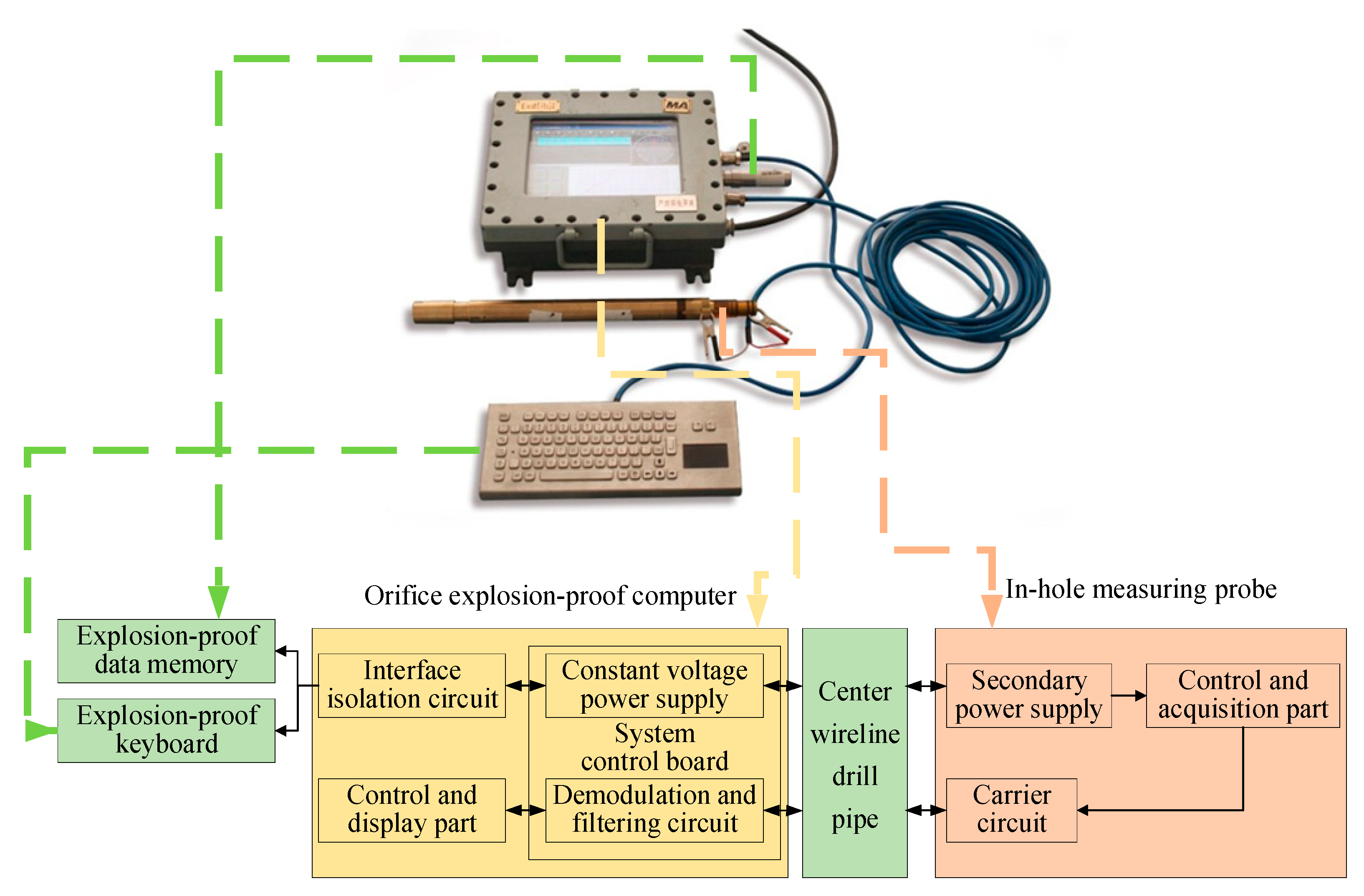
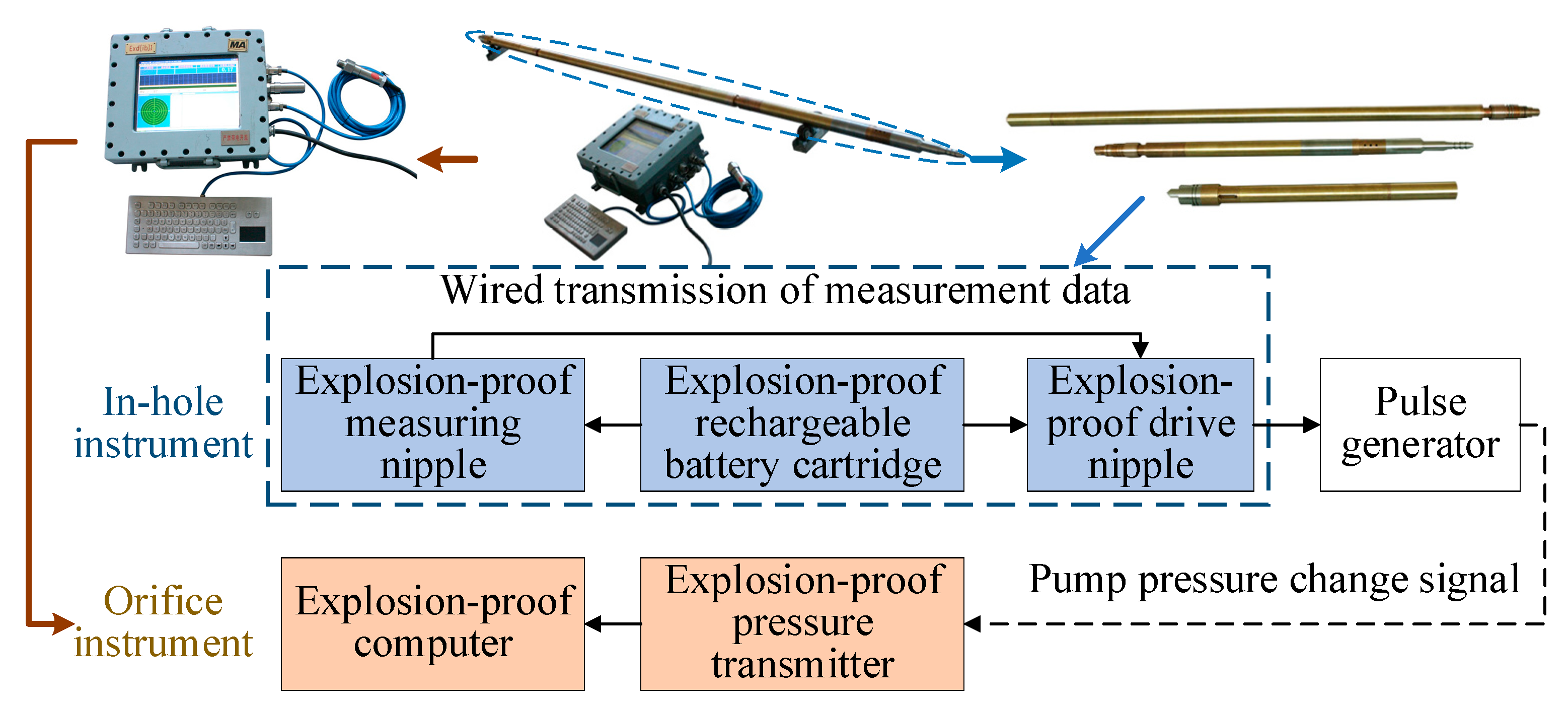
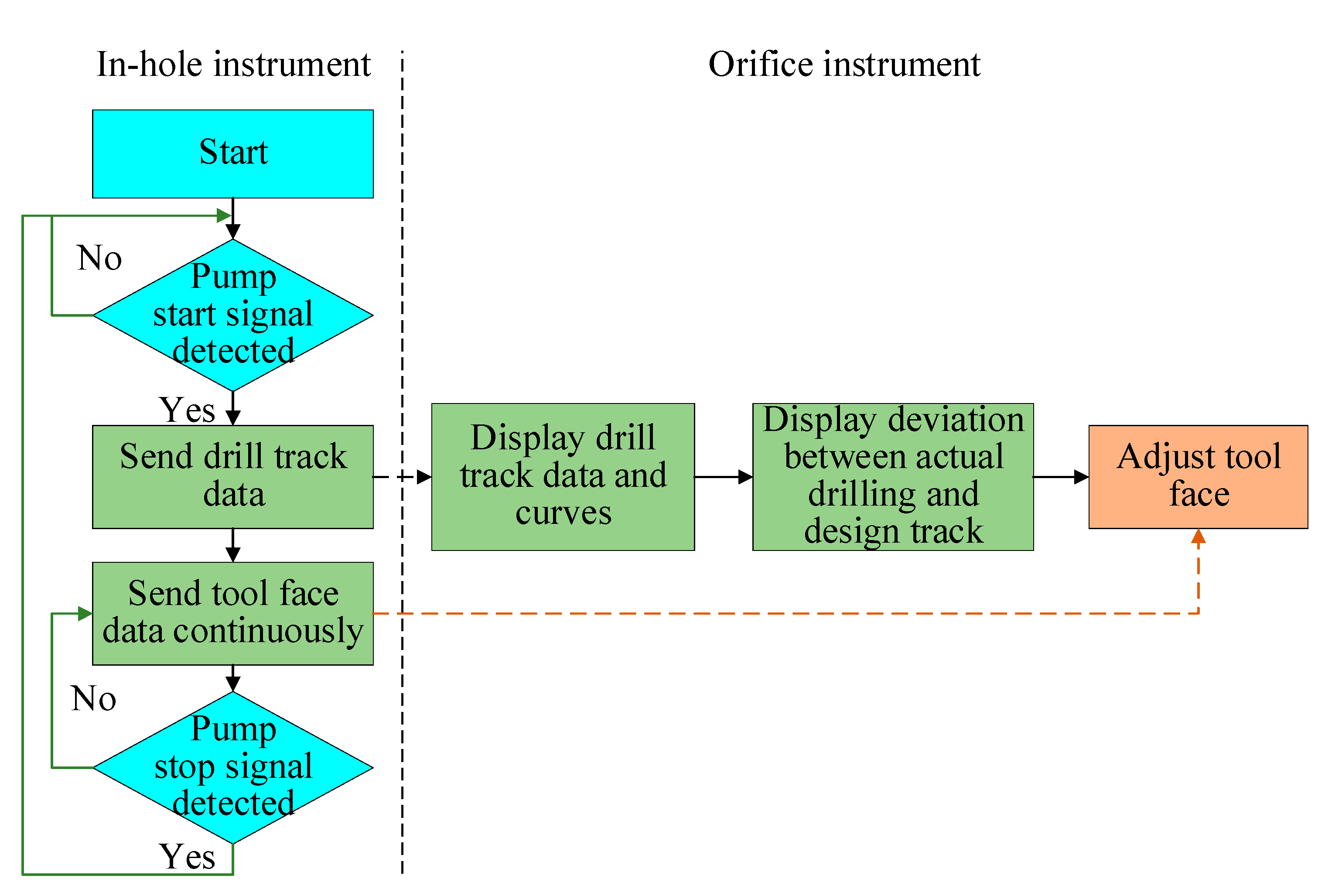
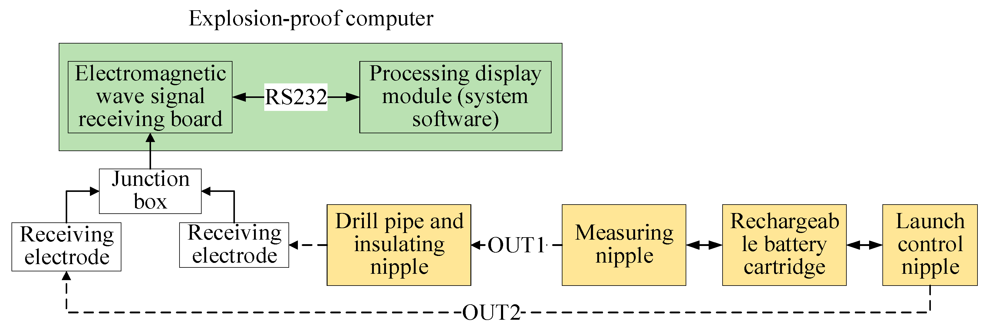
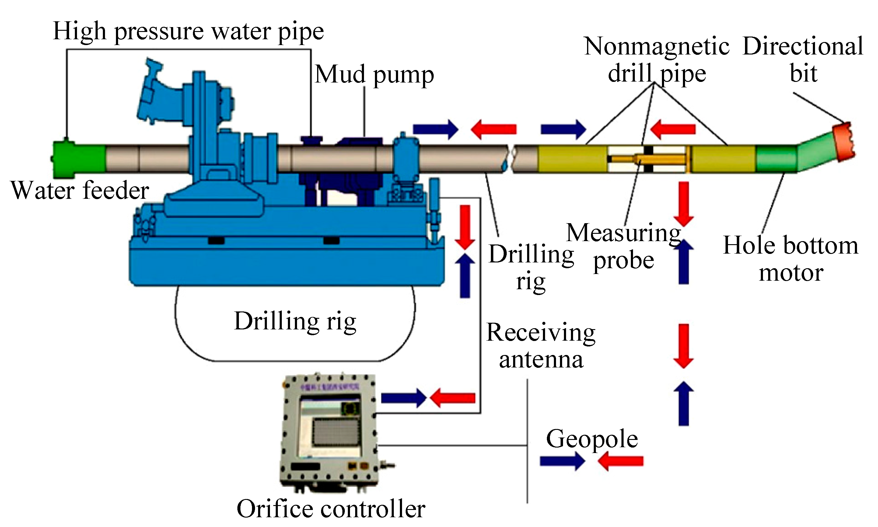
2.2. Measurement while Drilling (MWD) Technology

The MWD system is mainly used for monitoring while drilling during the construction of horizontal directional drilling in the coal mine. It can measure the main parameters such as the drill angle, azimuth angle and tool face angle while drilling. At the same time, it can realize the real-time display of the drilling parameters and drilling trajectory. It is convenient for the drilling personnel to understand the drilling construction situation at any time, and adjust the face angle and process parameters of the screw drilling tools in a timely manner, so that the drilling can be extended as far as possible according to the design trajectory [40,41].
According to different signal transmission modes, MWD systems can be divided into two categories: wired MWD systems and wireless MWD systems. Among them, the mine wireline MWD system is the most widely used and most developed MWD system in the field of directional drilling in coal mines [42,43,44]. The system is composed of in-hole equipment and orifice equipment, in which the in-hole equipment is composed of a measuring probe pipe, a non-magnetic drill pipe and other supporting equipment, while the measuring probe pipe is generally composed of a measuring unit, a signal transmission unit and a power supply unit [45]. The orifice equipment is composed of an explosion-proof computer, keyboard, memory and other supporting equipment, among which the explosion-proof computer is generally composed of a signal receiving unit, a data processing and display unit, a power supply unit, etc. As shown in Figure 4, the in-hole measuring probe pipe is installed in the non-magnetic drill pipe behind the screw drilling tool, the orifice equipment is installed near the rig console, and the central wireline drill pipe is connected from the hole bottom to the orifice in turn and the cable is used to connect with the orifice equipment when the mine wireline MWD system is used. During signal transmission, the central cabled drill pipe is equivalent to a coaxial cable. The drill pipe body and the signal transmission device form a signal transmission circuit. The signal transmission device in the center of the drill pipe is used as the signal line, and the drill pipe body is used as the signal ground to transmit the data in the hole to the orifice in real time. Wired signal transmission is widely used with the advantages of fast transmission speed and two-way signal transmission [46,47].
The research focus of the mine wireline MWD system is mainly on the power supply mode, signal transmission mode and signal transmission channel of the in-hole probe tube, and the related products are mainly the RS485 or RS232 wired transmission mode. The transmission channel is a specially designed central wireline drill pipe, and the power supply mode is the in-hole battery barrel, such as the DGS drilling guidance system of the Australia VLD Company, and the YHD1-1000 (A) MWD system of Xi’an Research Institute, etc. [48,49,50]. However, the use of an in-hole battery cartridge for power supply has some disadvantages, such as affecting the signal transmission and working stability, easy damage to the instrument, measurement lag, and increased use and maintenance costs. In view of the shortcomings of a battery power supply, the mine wire MWD system YHD2-1000 (A), based on explosion-proof computer power supply, was developed through the innovation of the power supply mode of the measuring probe tube and the signal transmission technology [51]. The system is composed of an explosion-proof computer, explosion-proof keyboard, explosion-proof data memory and explosion-proof measuring probe, as shown in Figure 5. The explosion-proof computer at the orifice uses the explosion-proof keyboard for human-computer interaction, and the explosion-proof data memory is used for file import and export, which can receive and process the measurement signals while drilling in real time and can also supply power for the in-hole measuring probe tube. The measuring probe uses the power supply provided by the orifice explosion-proof computer to work. After collecting the data on the drill angle, azimuth, tool face angle, etc., the data are sent to the orifice through the central wireline drill pipe, which is received and displayed by the explosion-proof computer. The measuring probe in the hole will stop working when the communication line is disconnected after completing the measurement [52,53].
The specially designed central wireline drill pipe is used as the signal transmission channel in the mine wireline measurement while the drilling system, which can receive the two-way communication of signals inside and outside the hole while supplying power for the instruments in the hole. It is widely used with a fast transmission speed and the transmission of large amounts of data.
However, there are also problems, such as the complex structure of drill pipe, high production and use costs, and the large through-hole structure of the drill pipe, which limit the overall mechanical performance of its joint parts, many faults or damages, poor anti-interference ability, suitability for sliding directional drilling of screw drill tools, and not meeting the requirements of efficient composite directional drilling of directional drilling [40,54], whereas the wireless MWD system reduces the requirements for special drill pipes. It mainly includes mud pulse telemetry, electromagnetic wave, acoustic wave, intelligent drill pipe and optical fiber five transmission modes, among which the mud pulse and electromagnetic wave technology are relatively mature [47]. Through research on key technologies such as in-hole engineering parameter measurement, mud pulse carrier signal transmission, intermittent working mode design and control, orifice signal reception and demodulation processing, the mine wireless MWD device YHD3-1500 based on mud pulse has been developed, and its overall structure is as shown in Figure 6 [55].
The working process is shown in Figure 7. The specific working principle is as follows. The probe pipe is connected to the back of the screw drilling tool during the process of drilling. The measuring nipple starts to collect the in-hole engineering parameter data such as the drilling track parameters (dip angle and azimuth angle) and the directional drilling tool status parameters (tool face angle) and codes them after detecting the stop signal of the mud pump through the probe pipe. The flow channel area of the hydraulic channel of the pulse generator is adjusted by the drive nipple according to the preset coding rules when the mud pump start signal is detected. The change of flow channel area will cause a change of flow resistance, which will lead to the change of outlet pressure of the mud pump. The pressure transmitter installed at the outlet of the mud pump collects the pressure change signal and transmits it to the explosion-proof computer. The pressure change curve is converted into borehole trajectory data by the explosion-proof computer according to the preset coding rules, and they are displayed in a data table and trajectory curve, providing the basis for borehole trajectory adjustments. After the data transmission is completed, the measuring probe tube stops working, the six channels in the pulse generator return to the initial state and the mud pump pressure returns to the normal value. Consequently, the normal drilling begins [56,57].
The drill pipe string and coal-bearing formation is taken as the signal transmission channel by the mine electromagnetic wave wireless MWD system. It has a fast data transmission speed and low requirements for the quality of drilling flushing medium and the working stability of the drilling mud pump [47]. The system consists of in-hole instruments and orifice instruments as shown in Figure 8, and the corresponding schematic diagram is shown in Figure 9. The working principle is as follows. The measuring nipple, the charging battery cartridge and the generator control nipple are connected to form the instrument in the hole, and it works according to the preset working mode and the start and stop status of the mud pump. The measuring nipple sends the detected parameters to the launch control nipple when data measurement and transmission are required. The launch control nipple sends the measured data through the upper drill string of the insulated nipple and the lower drill string of the insulated nipple in a wireless electromagnetic wave manner according to the preset coding rules, transmitting the data to the orifice through the upper drill string and the coal-bearing formation. The receiving electrode installed in the coal-bearing formation at the hole mouth and on the drilling equipment collects the uploaded electromagnetic wave signal and transmits it to the signal acquisition board in the explosion-proof computer through the wired mode. The signal is demodulated by the acquisition board according to the preset coding rules, and the correct in-hole process parameter data are obtained, then displayed on the screen through the data processing software in the explosion-proof computer [58].
Automatic vertical drilling technology has been developed on the basis of measurement while drilling and formation evaluation while drilling, real-time drilling data acquisition—processing—application technology, closed-loop rotary steering drilling technology and automatic drilling rig development [59]. This technology is an active deviation prevention technology aiming at vertical drilling. It uses the downhole closed-loop control and ground monitoring technology to measure the hole deviation in real time during the bit drilling process, and makes the bit return to the vertical direction by controlling the action of the deviation correction mechanism on the drilling tool in real time. At present, the existing automatic vertical drilling systems in the world have applied the rotary steering drilling technology, such as the power V system of Schlumberger Company, which integrates the power drive technology; while the VertiTrak system of Baker Hughes integrates the AutoTrak technology, and even has the same key working principle and anti-deviation mechanism [60,61,62].
During the drilling process, the drilling track extends along the direction of hole inclination. It is difficult to avoid well deviation due to the influence of many subjective and objective factors. In the actual drilling process, the drilling trend and the extension direction of the drilling track depend not only on the mechanical characteristics of the interaction between the bit and the formation, but also on the structure of the bit and the anisotropy of the formation [63,64,65,66]. At present, the sliding directional drilling technology and the composite directional drilling technology used in the underground directional drilling construction of coal mines are both “geometric guided” drilling methods, that is, the trajectory control is based on the deviation of the spatial geometric parameters of the actual drilling trajectory and the design trajectory, which solves the problem of drilling trajectory control in the thicker and stable target strata [67]. However, the drilling track easily deviates from the target stratum when the thickness of the target stratum is small and the fluctuation is large, and it is impossible to ensure the extension along the target stratum. Therefore, it is of great significance to analyze the stress analysis of complex coal seams on drilling tools and reveal the law of its influence on the drilling trajectory for improving the drilling rate, coal seam drilling rate and drilling efficiency.

3. Impact of Typical Complex Coal Seams on the Deviation of Drilling Tool Track

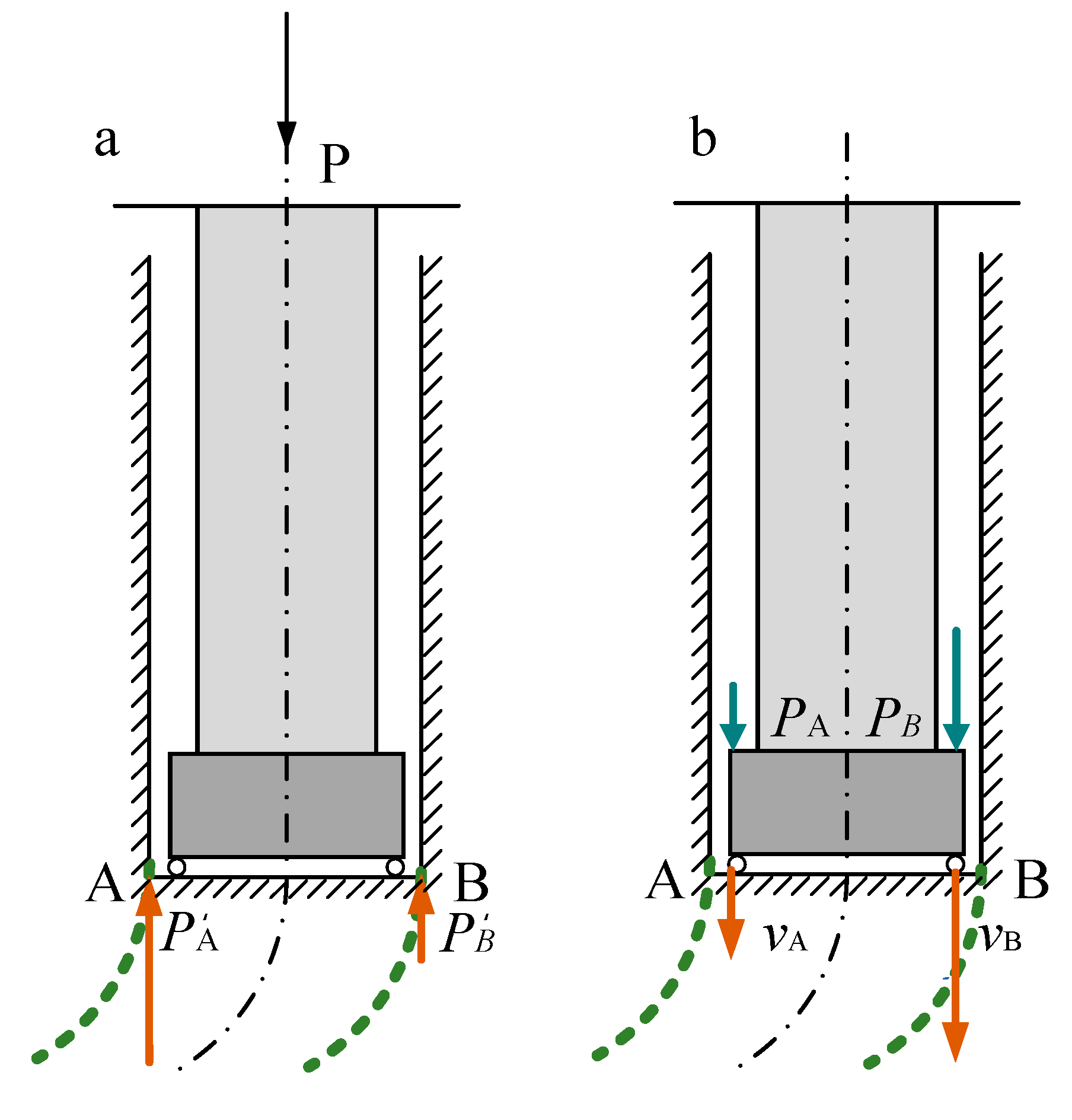
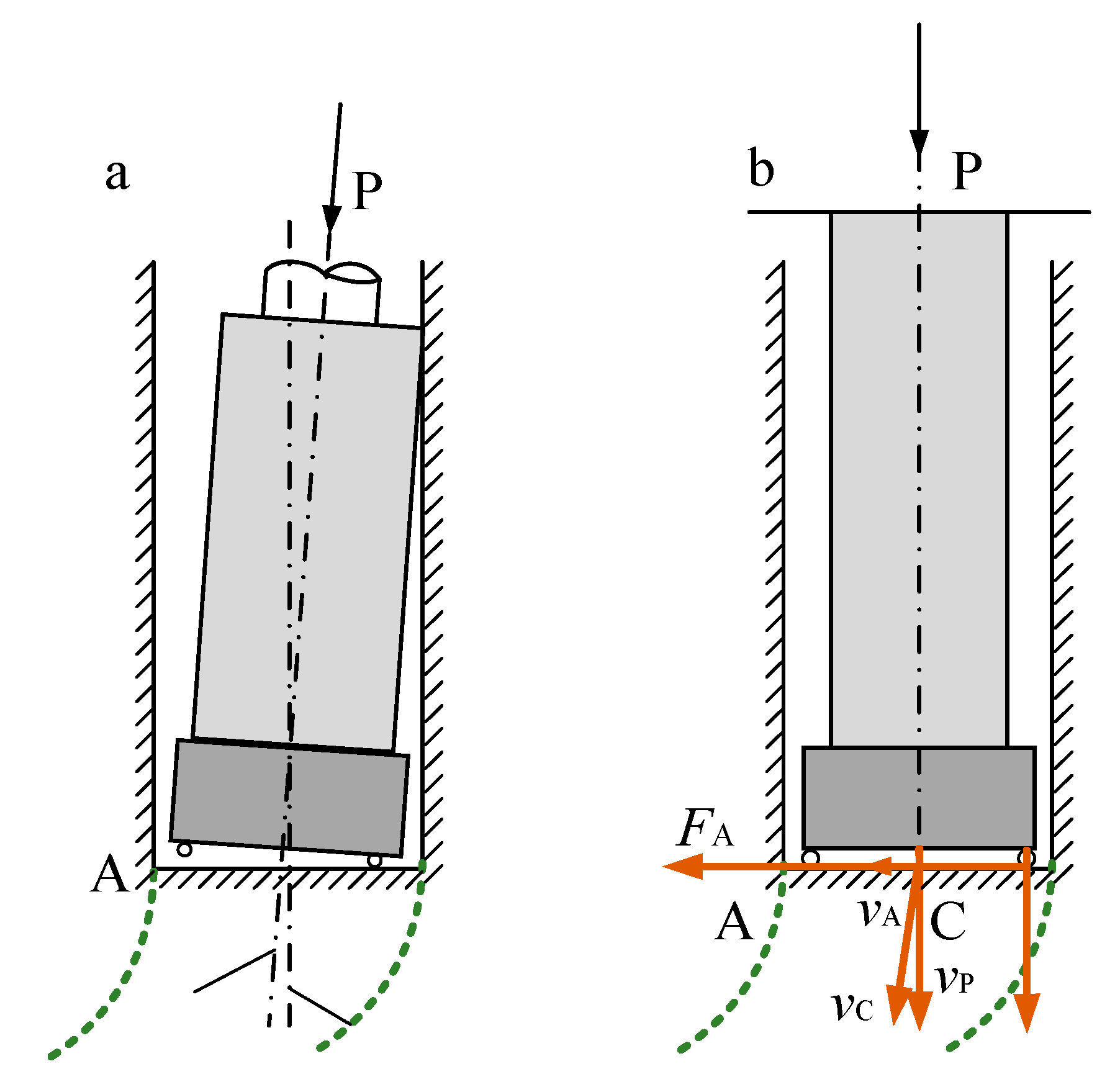
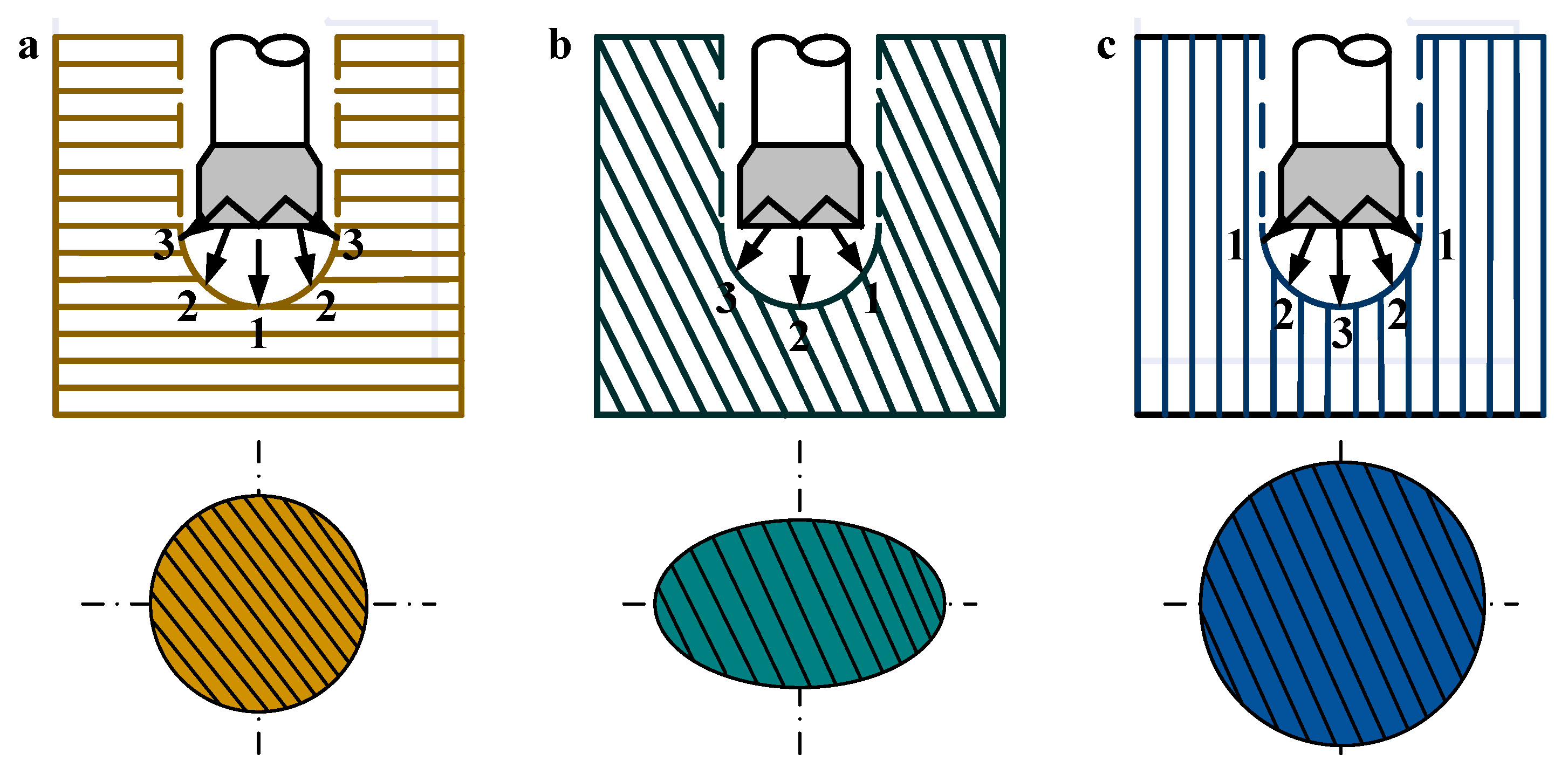
3.1. Conditions of Borehole Bending

The drilling bending must have the mechanical conditions, space conditions and position conditions to make the drill axis deviate from the drilling axis. Among them, the mechanical and spatial conditions are the necessary conditions for the drill axis to deviate from the drilling curve, and the position conditions are the sufficient conditions for the drill axis to deviate from the drilling axis [68].
Mechanical Conditions
(1) The axial force on the bit lip is unbalanced when the bit contacts the hole bottom, and the axial breaking speed of the hole bottom plane is fast or slow, that is, the uneven and asymmetric breaking of the hole bottom plane, and the drilling speed is poor, which makes the bit axis possibly deviate from the original bit axis. There are two kinds of unbalanced stress conditions on the bit plane. As shown in Figure 10a, the bit axis is perpendicular to the hole bottom plane, and the bit pressure is evenly distributed on the bit lip surface, but the degree of rock fragmentation at the hole bottom plane is different. It is difficult to break the rock at end A, and the breaking resistance is large, resulting in a low breaking speed, which leads to the deviation of the drilling axis to the side of end A. The other is as shown in Figure 10b, where the axis of the drill bit is perpendicular to the hole bottom plane. The weight on the bit is not evenly distributed on the bit lip, but the rock at the hole bottom plane is uniform and the breaking resistance is the same. The axial pressure at end A is less than that at end B, resulting in the breaking speed at end B being greater than that at end A, resulting in the deviation of the drilling axis to the side of end A.
(2) The lower coarse diameter drilling tool is skewed, the drill bit axis deviates from the original drill hole axis at an angle, and the weight on the bit is no longer applied to the drill bit in the vertical direction of the drill hole, resulting in asymmetric hole bottom breakage, which may lead to hole deviation (Figure 11a).
(3) The drill bit is subjected to axial and radial forces at the same time. The axial pressure acts on the hole bottom vertically along the drill bit axis, and the lateral force FA acts on the hole wall radially along the drill bit (Figure 11b). The drill bit breaks the hole bottom axially while cutting the hole wall laterally. The actual cutting direction is the vector combination direction vc of the axial breaking speed vp and the lateral cutting speed va, as shown in Formula (1) Therefore, the actual breaking direction of the bit curve deviates from the original drilling axis.
v c = v a + v p
(1) Mechanical Conditions
(2) Space condition: it refers to the gap between the lower coarse diameter drilling tool and the hole wall.
(3) Position condition: it refers to the direction of the bit force is fixed, the relative size is fixed, and the bit tilting direction is fixed.

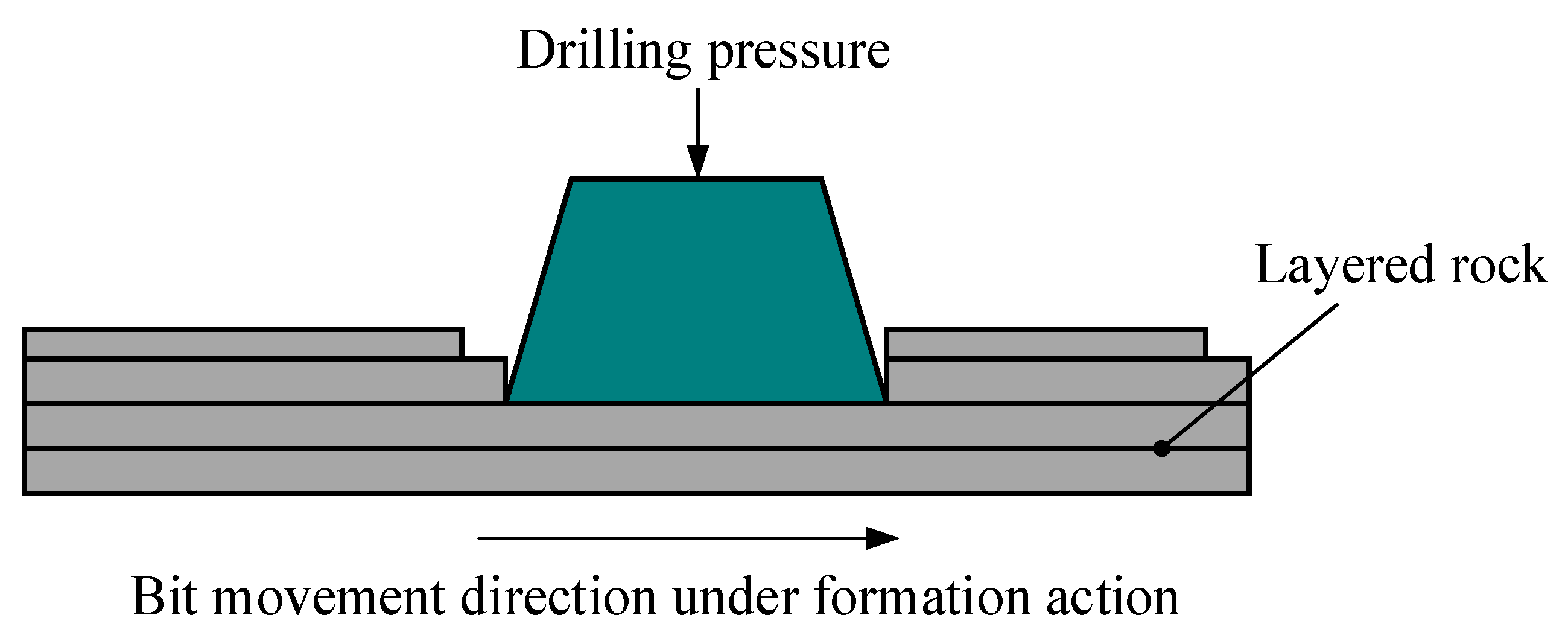
3.2. Reasons for Hole Bending

Borehole bending is a common and widespread phenomenon in drilling production, and the formation of bending conditions is the result of the joint action of subjective and objective factors. The theoretical study of well deviation of conventional mud drilling formation shows that the geology is heterogeneous [69,70,71], the physical properties of each layer are different, the formation drillability and bedding dip angle are also different and the significant difference of well deviation degree indicates that the formation factor is often the dominant factor affecting the well deviation [72]. The influence of formation on well deviation mainly includes the following four aspects.
(1) Influence of inclined layered strata
Because the rock at the layered interface cannot support the drilling pressure for a long time and tends to be crushed along the vertical plane when drilling the inclined layered formation, a small, inclined step is formed on the plane at the downdip side of the borehole. This small, inclined step exerts a lateral force on the bit, pushing the bit towards the updip direction of the formation, resulting in the well deviation, as shown in Figure 12 [73].
(2) Influence of rock anisotropy
The physical and mechanical properties of strata with bedding and schistosity are different in different directions. The rock stratum perpendicular to the bedding direction has the least hardness, the smallest breaking resistance and the fastest breaking speed; while the rock stratum parallel to the bedding direction has the greatest hardness, the highest breaking resistance and the slowest breaking speed; The hardness, breaking resistance and breaking speed of the rock stratum in the direction of oblique intersection with the bedding are between the above two. The natural trend will inevitably lead to well deviation when the local stratum is inclined. Figure 13 shows the hole breakage of the bit and the ground surface in different directions.
Figure 13a shows the hole breakage of the bit and the formation in different directions. In Figure 13b, the drill bit is oblique to the formation surface, and the drill bit is subject to a force from the dip direction of the formation—the formation deflecting force, which makes the drill bit axis force deflect to the direction perpendicular to the formation surface, and the drill hole is elliptical. In Figure 13c, due to the low hardness perpendicular to the layer, the rock on the hole wall is easily broken, the hole diameter formed is large, and the hole wall gap is large, which makes the bit stability poor, and the hole is also easily bent.
(3) Influence of soft and hard interlaced strata [74]
The influence of the drill bit on the bending of the hole when it passes through the soft and hard interbedding depends on the angle δ of contact of the hole axis (δ refers to the residual angle between the borehole axis and the normal of the rock layer) and the hardness difference of soft and hard rock layers. As shown in Figure 14a, WOB can be decomposed into component C perpendicular to the layer and component N parallel to the layer during drilling, as shown in Formula (2)
P = N + C
N is the sliding force of the drill bit on the rock layer, it is calculated as follows.
N = Pcos θ
The drill tool will slide along the rock layer when the sliding force is greater than the friction resistance between the drill bit and the rock layer, and the drill hole will bend along the direction of the rock layer (shown in Figure 14c). The smaller the stratum angle δ, the bigger the sliding force. Figure 14a shows the drill bit entering a hard rock stratum from a soft rock stratum when the stratum angle is greater than the critical value. When the bit enters the layer, the force on the lip is unbalanced, and the combined force of the hole bottom reaction at the hard rock end on the layer is greater than the hole bottom reaction at the soft rock end. Not only does the drill bit have uneven breakage with asymmetric penetration rate and hole bottom at both ends, but also it will produce a tilting moment M, which will twist the drill bit and make it bend along the upward inclination direction of the ground—that is, perpendicular to the plane direction. The calculation of M is:
M = 2 3 ( σ n σ m ) ( R 2 X 2 ) 3 2
where, σ n is the indentation hardness of hard rock; σ m is the indentation hardness of soft rock; R is the drill radius; X is the distance from the drill axis to the contact surface of soft and hard layers.
Figure 14b shows the drill bit entering from hard rock stratum to soft rock stratum when the stratum angle is greater than the critical value. According to the unbalanced stress on the drill bit at the bottom of the hole, the drilling speed on the soft rock side of the drill bit on the layer is fast, while the drilling speed on the hard rock side is slow, and the resulting tilting torque makes the drill hole tend to bend downward toward the formation. To sum up, the bending direction of the borehole from hard rock strata to soft rock strata is exactly opposite to that from soft rock strata to hard rock strata when drilling in alternate soft and hard rock strata.
(4) Influence of inclined broken-layered rock
When the bit is drilling in the inclined broken-layered rock, the bit tooth is easy to break the rock in the up-dipping direction of the formation to form more rock cuttings. Due to the imbalance of rock breaking on both sides of the inclined broken formation, an additional oblique force is generated to force the bit to constantly change the drilling direction. Consequently, the well deviation occurs.
To sum up, the regularity of borehole bending under the influence of geological factors is summarized as follows:
(1) The bending strength of the borehole is smaller than that in heterogeneous rock when drilling in homogeneous rock. The higher the degree of anisotropy of the rock, the greater the bending strength of the borehole [75,76,77].
(2) The borehole bends in the direction perpendicular to the bedding plane when drilling in the rock with developed bedding and schistosity. The stratum angle of the borehole is greater than the critical value, the borehole direction is perpendicular to the strike of the stratum, the top angle drifts upward and the azimuth angle is stable. The borehole azimuth is oblique to the strike of the bedding plane, with both the top angle drifting upward and the azimuth angle bending, and the azimuth change tends to be perpendicular to the strike of the bedding plane. If the stratum angle of the borehole is less than the critical value, the borehole will slide along the stratum and the azimuth angle will vary. The bending strength of the borehole is related to the size of the stratum angle. The bending strength of the borehole is the largest when the layer angle is about 45° [75,78,79].
(3) When drilling in soft and hard interbedded rocks, because the bending strength of the drill hole is large when it enters the hard rock stratum from the soft rock stratum, but the bending strength is small when it enters the soft rock stratum from the hard rock stratum, the final trend of the bending of the drill hole is still vertical to the layer [80,81,82].
(4) When the borehole passes through loose non-cemented rock, large karst caves and old holes, the borehole tends to sag. When the borehole encounters hard inclusions, it may bend in any direction. The harder the inclusions are, the stronger the bending is.
(5) The azimuth angle changes little when the hole top angle is large. The azimuth angle changes greatly when the top angle of the borehole is small [83,84,85]. According to the general rule, the azimuth bending is often consistent with the rotation direction of the drilling tool. Only in boreholes where the top angle is close to zero, the azimuth change is uncertain.
(6) Even if the rock anisotropy is strong and the degree of soft and hard unevenness is large, the drilling will not produce large bending when drilling vertical holes in horizontal or nearly horizontal layered rocks.
(7) The bending strength of the drilling hole is large if the hole wall clearance is large, and the rigidity of the drilling tool is poor. The vertical shaft and guide pipe are not installed correctly, and the drilling hole is deviated in the direction of incorrect installation [86].
(8) Because the steel particles are mostly concentrated at the lower left of the hole bottom when the steel particles are drilled in the inclined hole, the hole depth bends to the right and the upper right, and the top angle and azimuth angle change. This bending trend may be intensified or weakened due to the influence of geological factors.

4. Stratum Force Theory and Method of Complex Coal Seams

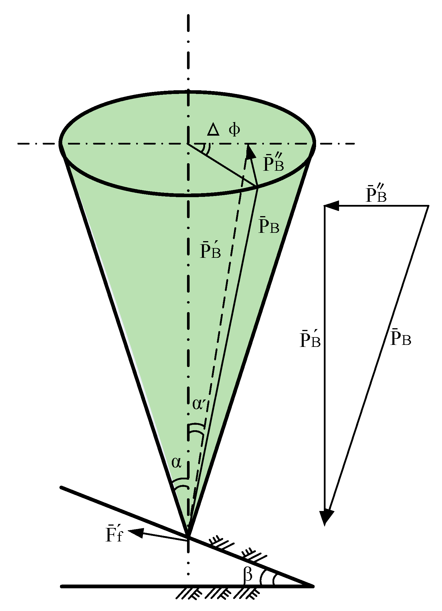
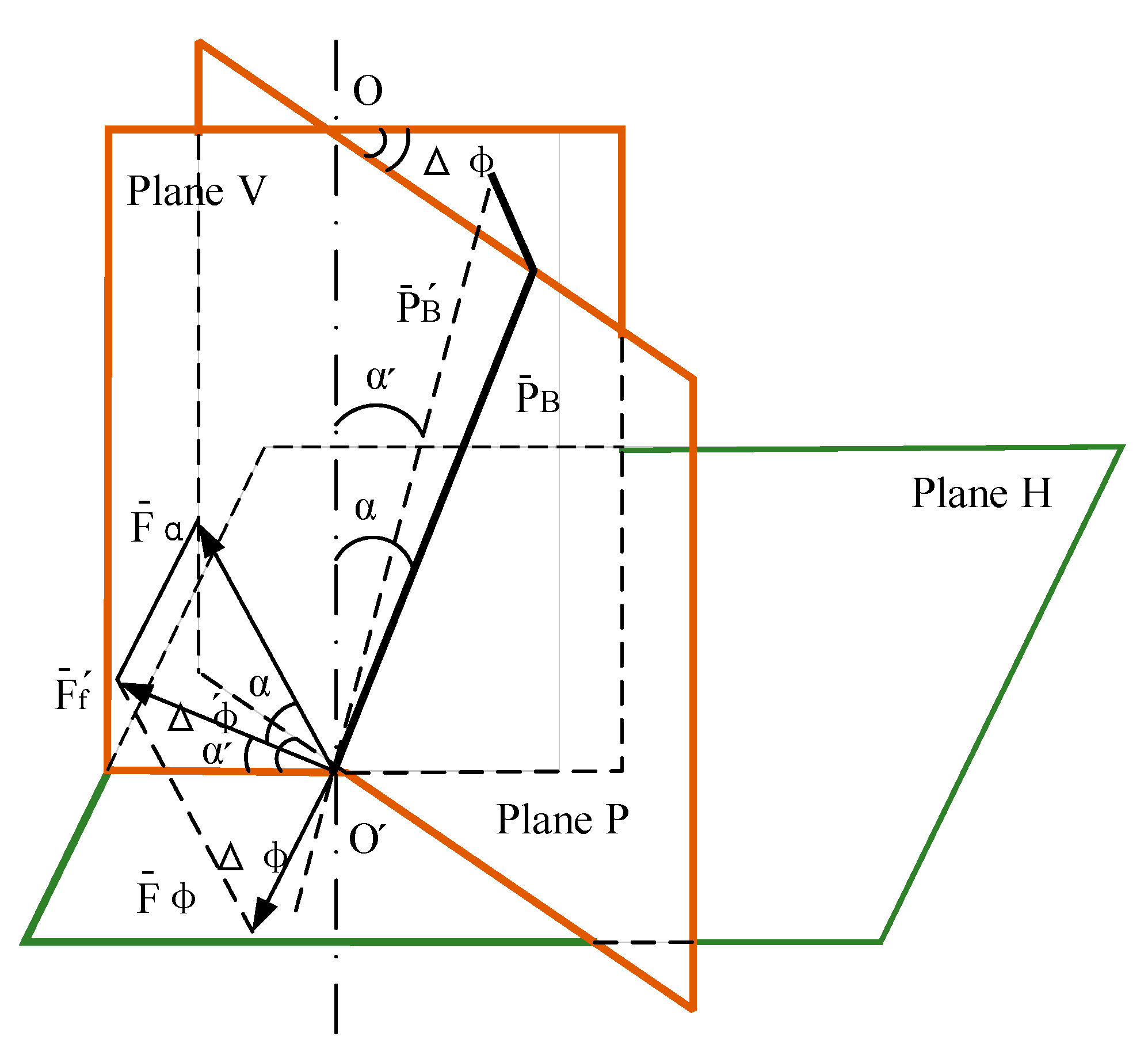
4.1. Quantitative Analysis of Formation Force

On the basis of qualitative analysis of the influence of complex coal seams considering geological factors on drilling trajectory, quantitative analysis of formation forces must be carried out in order to predict and control well trajectory [87]. The formation force refers to the force effect of the deviation of the formation on the bit, which includes the formation variable well deviation force and the formation variable azimuth force. The theory and method of formation force is to quantitatively analyze and calculate the formation force by comprehensively considering the influence of formation anisotropy and bit anisotropy, formation dip and strike, drilling direction and weight on bit and other factors. In directional drilling, the drilling pressure PB is not generally located in the formation profile, and there is an angle between the drilling direction and the formation updip direction, so the formation force has both the variable well deviation effect and the variable azimuth effect, that is, the formation variable well deviation force Fa and the formation variable azimuth force F φ [88].
The drilling pressure cone shown in Figure 15 has a half apex angle of well deviation α. The drilling pressure P B is a generatrix of the cone, and the included angle between the plumb plane (P plane) and the formation profile is Δφ. Then, P B = P B + P B . The formation force caused by the component P B is as follows:
F f = Htg ( β α ) cos α / cos α P B 1 Htg 2 ( β α )
in which α = arctg ( tg α · cos Δ ) , Δ ϕ = ϕ W ϕ S . ϕ W is the azimuth of the well bore, ϕ S is the azimuth of the formation tilt up, H is the comprehensive cutting anisotropy index, and β is the dip angle of the stratum.
By further decomposing F f into F f = F α + F ϕ , the follows can be deduced:
F α = F f cos Δ ϕ , F ϕ = F f sin Δ ϕ
As shown in Figure 16, the relationship between Δ ϕ and Δ ϕ is:
Δ ϕ = arccos [ cos Δ ϕ cos α cos α + sin α sin α ]
From this formula, it is easy to derive Lubinski’s full angle formula. Because of α < α , Δ ϕ Δ ϕ can be deduced when α is small. Then F α and F ϕ can be simplified to the following approximate formula:
F α = F f cos Δ ϕ  
F ϕ = F f sin Δ ϕ
The symbol of F f specified as pointing upward is positive and pointing downward is negative. The relationship between the symbols, properties and quadrants of the formation oblique force F α and the formation azimuthal force F ϕ is shown in Table 1 and Table 2 [88].
To sum up, it can be seen that the formation variable well deviation force can be the deflecting force or the declination force, and the formation variable azimuth force can be the increasing azimuth force or the decreasing azimuth force. In general ( β   <   45 °   <   β c ), the formation variable well deviation force always makes the well body close to the formation normal direction; however, the formation variable azimuth force always makes the well bore drift close to the formation dip direction (up dip or down dip). When α   <   β , F ϕ makes the well bore drift close to the upward inclination of the formation (except for drilling along the downward inclination). When α   >   β , F ϕ makes the well bore drift towards the downdip direction of the formation (except for drilling along the updip direction). When the drilling direction is consistent with the formation dip direction, the formation variable azimuth force is zero, which does not affect the well bore orientation.

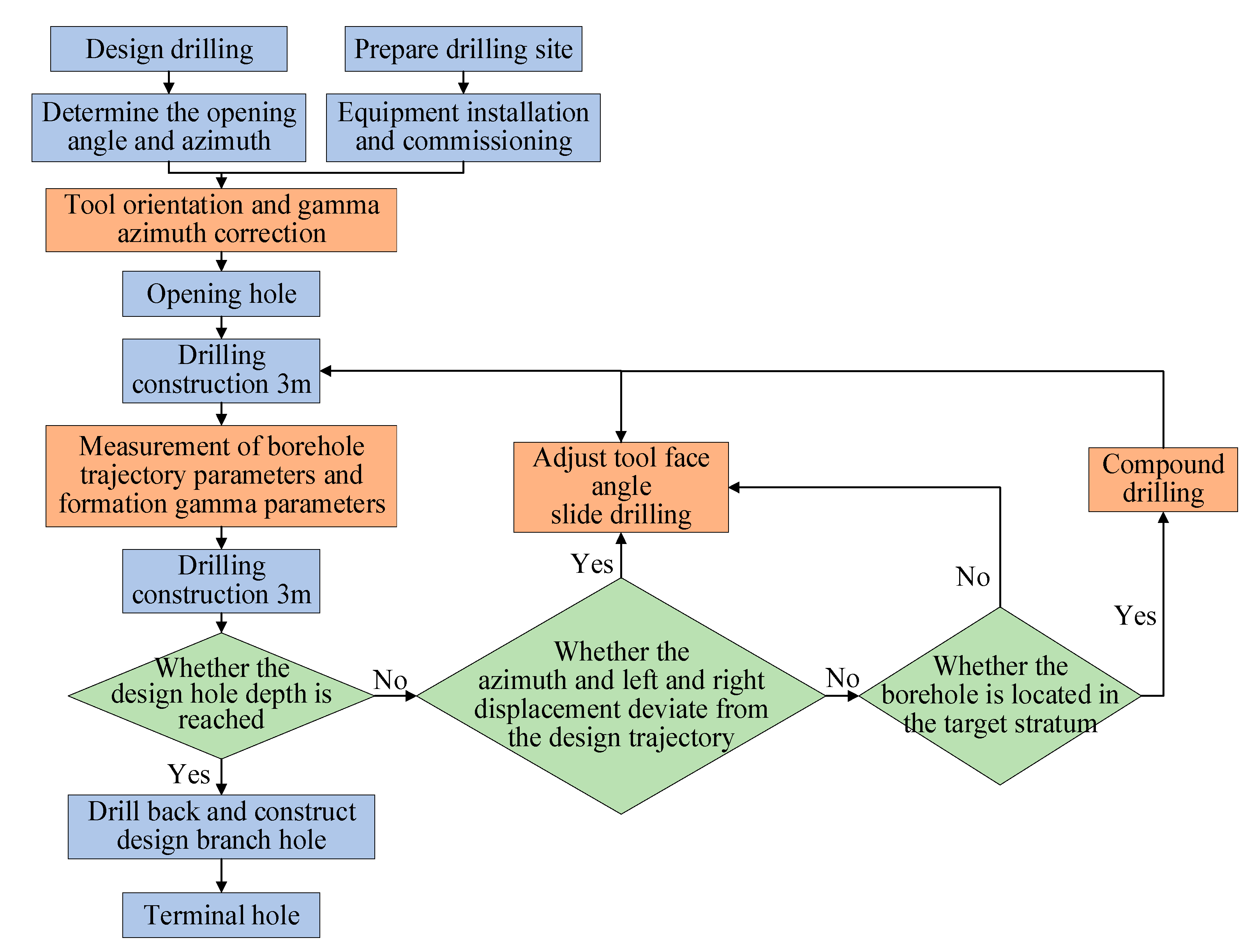
4.2. Geosteering Drilling Technology

Combining the formation identification technology, sliding directional drilling and composite drilling, with the help of the drilling space positioning function of the formation identification, the sliding directional drilling trajectory control function and the efficiency and smooth characteristics of the composite drilling, the geosteering directional drilling technology gives play to the technical advantages of composite drilling while manually controlling the drilling trajectory, and improves the hole formation rate, coal seam drilling rate and hole formation efficiency of the directional long hole drilling for gas extraction [89].
The key of geosteering directional drilling technology is the identification of strata and the manual control of drilling trajectory [90,91,92,93]. Its core is how to grasp the conversion opportunity between sliding directional drilling technology and composite drilling technology according to the total space position of the actual drilling trajectory during drilling construction [94]. After identifying the formation characteristics, the specific implementation of the sliding directional drilling process and the composite drilling process should be based on the qualitative analysis of the impact of geological factors on the drilling trajectory and the quantitative calculation of the formation force [95,96], and the specific adjustment of the drilling process parameters to achieve the prediction and control of the borehole trajectory or the drilling trajectory. In the stage of sliding directional drilling, manual real-time continuous control of the bending direction of the drilling track can be realized by adjusting the face angle of the screw drilling tool [97]. In the compound drilling stage, due to the continuous rotation of the tool surface of the screw drilling tool, it is impossible to realize the manual control of the drilling track. However, according to the experimental data, the azimuth angle and inclination angle of the drilling track increase and decrease, respectively, during the composite drilling, and its slope rate is generally lower than that of the sliding directional drilling. Based on this law, the corresponding drilling method can be selected according to the actual deviation of the drilling track and the position of the drilling hole in the formation. During the drilling process, the bending law of the composite drilling hole should be used to control the drilling track as much as possible. The process flow is shown in Figure 17 [98].

5. Conclusions

With the expansion of coal mining scope, the increase in mining intensity and mining depth, complex coal seam occurrence conditions have brought serious threats to coal mine production safety. The frequency and intensity of disasters such as coal and gas conflict, mine water inrush and rock burst are increasing, and coal mine safety production is facing new and severe challenges. Its challenge is mainly reflected in the influence of geological factors on the deviation of well or drilling track in the process of energy exploitation. The essence of well deviation caused by geological factors comes from two factors, namely the non-uniformity of formation drillability and formation inclination, including the non-uniformity of formation drillability in different directions, soft and hard staggered formation, inclined broken-layered rock, etc. Its influence incentive is reflected in the asymmetric cutting of the bit to the bottom of the hole, which makes the bit axis tilt relative to the hole axis, thus making the newly drilled hole deviate from the original design hole.
As one of the most direct and effective technical means to prevent and control coal mine accidents and serve safe and efficient coal mining, directional drilling plays a huge role in the fields of coalbed methane development, water disaster prevention, hidden geological factors exploration and emergency rescue in coal mine areas [92]. Directional drilling technology can ensure the effective extension of the drilling track in the predetermined horizon and improve the drilling rate of the target formation. This can increase the efficiency and quantity of gas drainage in boreholes, and improve the level of gas control in coal mines. In the aspect of water hazard prevention and control, it can increase the proportion of effective hole sections drilled into the aquifer and realize the advance regional exploration and control of water hazard hidden dangers in the coal mine. In the exploration of geological abnormal bodies, the probability of drilling into geological abnormal bodies can be improved, and the precise spatial location of geological abnormal bodies can be obtained, providing safety guarantees for mining operations. In addition, the directional drilling technology can carry out multi-branch hole construction, and the drilled holes can evenly cover the entire working face. It has the advantages of high accuracy of drilling trajectory control, high drilling efficiency, wide coverage and high utilization rate of drilling, and has become the main technical approach for efficient gas extraction, water hazard prevention and geological anomaly detection in coal mine areas in China.

Author Contributions

Thesis subject and writing, M.K.; Measurement while drilling (MWD) technology, D.H.; Geosteering drilling technology methodology, X.G. All authors have read and agreed to the published version of the manuscript.

Funding

This research was funded by Youth Science and Technology Fund Project JE210010 (2021.01~2023.01). The funder is the School of Mechatronic Engineering in China University of Mining and Technology.

Institutional Review Board Statement

Not applicable.

Informed Consent Statement

Not applicable.

Data Availability Statement

Not applicable.

Conflicts of Interest

The authors declare no conflict of interest.

References

  1. Peng, Z. Drilling Technology for Complex Formations; Central South University Press: Changsha, China, 2016. [Google Scholar]
  2. Hou, Y.; Zhou, M.; Zhang, D.; Fang, Q.; Sun, Z.; Tian, Y. Analysis of four shield-driven tunnels with complex spatial relations in a clay stratum. Tunn. Undergr. Space Technol. 2022, 124, 104478. [Google Scholar]
  3. Zhang, X.Y.; Zhang, L.W.; Wu, J.; Fu, H.; Dian, L.Y. Tunnel stability analysis of coral reef limestone stratum in ocean engineering. Ocean. Eng. 2022, 265, 112636. [Google Scholar] [CrossRef]
  4. Sm, A.; Zd, A.; Zhen, H.A.; Ying, L.A.; Yu, S.B.C. Study on the stability of shield tunnel face in clay and clay-gravel stratum through large-scale physical model tests with transparent soil. Tunn. Undergr. Space Technol. 2022, 119, 104199. [Google Scholar]
  5. Kong, L.; Chen, H.; Ping, H.; Zhai, P.; Zhu, J. Formation pressure modeling in the Baiyun Sag, northern South China Sea: Implications for petroleum exploration in deep-water areas. Mar. Pet. Geol. 2018, 971, 154–168. [Google Scholar] [CrossRef]
  6. Fu, M.; Zhang, P.; Li, J.; Wu, Y. Observer and reference governor based control strategy to suppress stick-slip vibrations in oil well drill-string. J. Sound Vib. 2019, 457, 32–41. [Google Scholar] [CrossRef]
  7. Hong, L.; Irving, P.; Jaspreet, S. Identification and control of stick-slip vibrations using Kalman estimator in oil-well drill strings. J. Pet. Sci. Eng. 2016, 1404, 119–127. [Google Scholar] [CrossRef]
  8. Wu, M.; Cheng, J.; Lu, C.; Chen, L.F.; Lai, X.Z. Disturbance estimator and smith predictor-based active rejection of stick–slip vibrations in drill-string systems. Int. J. Syst. Sci. 2020, 51, 826–838. [Google Scholar] [CrossRef]
  9. Alkaragoolee, M.; Bryant, D. Investigation into the effect of friction decay factor on the modelling and attenuation of stick-slip vibrations of oilwell drilling systems. Oil Gas (Engl.) 2022, 8, 8. [Google Scholar] [CrossRef]
  10. Teng, X.; Qinfeng, D.I.; Ning, L.I.; Chen, F.; Zhou, B.; Wang, M. Measurement and Analysis of Stick-Slip Characteristics of Drill String in Ultra-Deep Wells. Pet. Drill. Tech. 2017, 45, 32–39. [Google Scholar]
  11. Kawasaki, T.; Yamaguchi, K.; Takada, T.; Takabumi, S.; Yousuke, N. Correlation between color measurement and alteration of drilling core in the fault crush zone. Geol. Data Process. 2010, 10, 86–87. [Google Scholar] [CrossRef] [Green Version]
  12. Matsuda, T.; Arai, T.; IkedaR; Omura, K.; Kobayashi, K.; Sano, H.; Sawaguchi, T.; Shimada, K.; Tanaka, H.; Tomita, T. The distribution pattern of minerals, chemical elements in the fracture zone at 1300 m depth of core recoverd from drilling passing through Nojima Fault by NIED. —Compared with the fracture zone at 1140 m depth. In Meeting of the Geological Society of Japan; The Geological Society of Japan: Tsukuba, Japan, 1998. [Google Scholar]
  13. Zhang, W.; Li, H.B.; Huang, Y.; Si, J.L.; Sun, L.W. Lithologic characteristics and fault zone structure revealed by No.2 hole cores of the Wenchuan Earthquake Fault Zone Scientific Drilling (WFSD-2). Geol. Bull. China 2012, 31, 1201–1218. [Google Scholar]
  14. Ji, K.; Xu, X.; Survey, J.G. Geothermal Well Drilling Positioning through CSAMT in Baoying Area, Jiangsu. Coal Geol. China 2018, 30, 80–84. [Google Scholar]
  15. Qiu, A.; Bo, Z.; Qiu, A.; Li, Z. Drilling Failure Analysis and Remedial Measures of Coalbed Methane Multiple Laterals Wells. Unconv. Oil Gas 2018, 5, 88–92. [Google Scholar]
  16. Sun, Q. Impact and treatment of geological faults on coal mine production. Sci. Technol. Wind. 2013, 8, 122. [Google Scholar]
  17. Li, X. Brief analysis of the impact of geological faults on coal mine production and treatment. Heilongjiang Sci. Technol. Inf. 2014, 34, 102. [Google Scholar]
  18. Liu, C. Research status and prospect of drilling technology in broken and complex formations in China. Gansu Sci. Technol. 2010, 26, 78–80. [Google Scholar]
  19. Bennion, D.B.; Thomas, F.B. Formation Damage Issues Impacting the Productivity of Low Permeability, Low Initial Water Saturation Gas Producing Formations. J. Energy Resour. Technol. 2005, 127, 240–247. [Google Scholar] [CrossRef]
  20. Bilardo, U.; Alimonti, C.; Chiarabelli, A.; Caetani, F.C. Formation water saturation from drilling fluid filtrate invasion: Comparison of displacement modelling and induction well log response. J. Pet. Sci. Eng. 1996, 15, 251–259. [Google Scholar] [CrossRef]
  21. Gao, H.; Feng, M.; Wang, J.; Yu, T.; Shuai, L. Calculation on water saturation of Changxing Formation reservoir in Yuanba Gas Field. Fault-Block Oil Gas Field 2014, 21, 348–351. [Google Scholar]
  22. Małkowski, P.; Ostrowski, Ł.; Bożęcki, P. The impact of the mineral composition of Carboniferous claystones on the water-induced changes of their geomechanical properties. Geol. Geophys. Environ. 2017, 43, 43–55. [Google Scholar] [CrossRef] [Green Version]
  23. Sakhno, I.; Sakhno, S.; Skyrda, A.; Popova, O. Numerical Modeling of Controlling a Floor Heave of Coal Mine Roadways with a Method of Reinforcing in Wet Soft Rock. Geofluids 2022, 2022, 3855799. [Google Scholar] [CrossRef]
  24. Zhou, X.; Cai, W.; Cao, X.L.; Xiong, C. Influence of water content on mechanical properties of rock in both saturation and drying processes. Rock Mech. Rock Eng. 2016, 49, 3009–3025. [Google Scholar] [CrossRef]
  25. Qin, K.; Di, Q.; Zhou, X. Nonlinear dynamic characteristics of the drill-string for deep-water and ultra-deep water drilling. J. Pet. Sci. Eng. 2022, 2091, 09905. [Google Scholar] [CrossRef]
  26. Li, Y.; Zhang, T.; Tian, Z.; Zheng, Y.; Yang, Z. Simulation on compound percussive drilling: Estimation based on multidimensional impact cutting with a single cutter. Energy Rep. 2021, 7, 3833–3843. [Google Scholar] [CrossRef]
  27. Xia, Y.; Du, R.; Sun, X.; Du, S. Countermeasures of ecologic phreatic water protection and mine water disaster prevention in northern Shaanxi Coalfield. Coal Sci. Technol. 2016, 44, 39–45. [Google Scholar]
  28. Bu, C. Application and outlook of detection, prevention and control technique of coal mine water disaster. China Coal 2014, 40, 100–108. [Google Scholar]
  29. Zhai, L. Comprehensive Exploration Technology of Water Disaster Prevention and Control in Coal Mining Roof. Procedia Earth Planet. Sci. 2011, 33, 303–310. [Google Scholar] [CrossRef] [Green Version]
  30. Zhang, J.; Yao, N.P.; Qiao-Qiao, L.I. Application of Directional Drilling Technology in Mines Geological Exploration. Saf. Coal Mines 2013, 44, 131–134. [Google Scholar]
  31. Ningping, Y.; Jie, Z.; Xing, J.; Hanjing, H. Status and Development of Directional Drilling Technology in Coal Mine. Procedia Eng. 2014, 73, 289–298. [Google Scholar] [CrossRef] [Green Version]
  32. Shi, Z.; Chao, X.U.; Quanxin, L.I.; Zhang, J. Application of MWD Directional Drilling Technology in Geologic Exploration in Underground Coal Mine. Saf. Coal Mines 2014, 45, 137–140. [Google Scholar]
  33. Li-Meng, D.U.; Hao, S.; Pan-Pan, Y.; Junfeng, L.V. Application of Horizontal Directional Drilling Technology in Geological Structure Exploration in Hudi Coal Mine. Explor. Eng. (Rock Soil Drill. Tunn.) 2014, 41, 38–43. [Google Scholar]
  34. My, A.; Fei, C.B.; Jl, A.; DP, A.; ZA, A. Frequency-Domain Full-Waveform Inversion Based on Tunnel Space Seismic Data—ScienceDirect. Engineering 2021, 181, 197–206. [Google Scholar]
  35. Joseph, A.; Udofia, U.; Ajang, R. Evaluation of the water quality of borehole water from a partially remediated oil spill site in Ikot Ada Udo, Akwa Ibom State, South–South Nigeria. Environ. Technol. Innov. 2021, 24, 101967. [Google Scholar] [CrossRef]
  36. Zhao, E.; Li, K.; Yang, X.; Deng, N. Speculum Observation and Trajectory Measurement in Gas Extraction Drilling: A Case Study of Changling Coal Mine. Geofluids 2021, 554, 292–306. [Google Scholar]
  37. Wang, H.; Dong, S. Spatial Transverse Vibration Simulation Model of Axially Moving Sucker Rod String under the Excitation of Curved Borehole. Shock. Vib. 2020, 2020, 3108718. [Google Scholar] [CrossRef]
  38. Ma, H.; Wang, Y. Formation drillability prediction based on PSO-SVM. In Proceedings of the IEEE 2010 10th International Conference on Signal Processing, Beijing, China, 25–27 August 2010. [Google Scholar]
  39. Al, A.; Ak, B.; Mbm, C.; RD, C.; OR, C. On the prediction of filtration volume of drilling fluids containing different types of nanoparticles by ELM and PSO-LSSVM based models. Petroleum 2021, 8, 424–435. [Google Scholar]
  40. Shi, Z.; Dong, S.; Yao, N. Directional drilling technology and equipment for near-horizontal measurement while drilling in coal mine. Coal Sci. Technol. 2013, 41, 6. [Google Scholar]
  41. Shi, Z.; Wen, R.; Fang, J.; Quanxin, L.; Gao, J. Development of MWD system for underground directional drilling in coal seams. Coal Sci. Technol. 2013, 43, 109–113. [Google Scholar]
  42. Vezhapparambu, V.S.; Ellefmo, S.L. Estimating the blast sill thickness using changepoint analysis of MWD data—ScienceDirect. Int. J. Rock Mech. Min. Sci. 2020, 134, 104443. [Google Scholar] [CrossRef]
  43. Gao, J. Research on Data Transmission Technology in Mine-used MWD Systems. Zhongzhou Coal 2016, 4, 115–121. [Google Scholar]
  44. Ghiselin, D. MWD/LWD offers faster, more complete real-time data technology. Offshore: Inc. Oilman 2013, 73, 55–56. [Google Scholar]
  45. Isheysky, V.; Sanchidrián, J.A. Prospects of Applying MWD Technology for Quality Management of Drilling and Blasting Operations at Mining Enterprises. Minerals 2020, 10, 925. [Google Scholar] [CrossRef]
  46. Ming, D.; Chen, Q. Coal and gas outburst monitoring system based on WSN. Procedia Eng. 2010, 73, 387–391. [Google Scholar]
  47. Lu, C.; Zhang, T.; Zhao, H. Improving the application depth of electromagnetic measurement while drilling (EM-MWD) systems by receiving signals from adjacent wells. J. Appl. Geophys. 2021, 195, 104468. [Google Scholar] [CrossRef]
  48. Wang, Q.; Huang, L. Research and application of mine MWD device based on external power supply. Coal Sci. Technol. 2013, 41, 12–15. [Google Scholar]
  49. Fang, J.; Shi, Z.; Li, Q.; Gao, J. Wired MWD device is used for underground directional drilling in new coal mines. Ind. Min. Autom. 2015, 41, 1–5. [Google Scholar]
  50. Vladut, T.; Tweedy, D.H. Development of a MWD system for geomechanical drilling: Proc CARE 88 (Conference on Applied Rock Engineering), Newcastle, 6–8 January 1988 P235–242. Publ London: IMM, 1988. Int. J. Rock Mech. Min. Sci. Geomech. Abstr. 1989, 26, 75. [Google Scholar] [CrossRef]
  51. Song, C.; Jia, N.; Ji, W.; Tian, D. Application of directional drilling technology and equipment in directional long drilling through layers. Drill. Eng. 2021, 48, 6–14. [Google Scholar]
  52. Duan, H.; Hao, S.; Wang, Y. Application of directional drilling technology and equipment in large-diameter and long drilling of roof. Coal Min. Mach. 2020, 41, 4–12. [Google Scholar]
  53. Cheng, J.; Wu, M.; Chen, L. Observer-Based Tracking Control for Suppressing Stick-Slip Vibration of Drillstring System. In Proceedings of the 2018 37th Chinese Control Conference (CCC), Wuhan, China, 15–17 July 2018. [Google Scholar]
  54. Wang, Y.; Ni, H.; Tu, Y.P.; Wang, R.; Xie, H. Experimental Study on Axial Impact Mitigating Stick-Slip Vibration with a PDC Bit. Shock. Vib. 2021, 211, 1–8. [Google Scholar] [CrossRef]
  55. Gao, W.; Sheng, L.; Dou, X.; Lei, Z.; Lin, L. CGDS Near-Bit Geosteering Drilling System and Its Application in China. In Proceedings of the SPE/IATMI Asia Pacific Oil & Gas Conference and Exhibition, Bali, Indonesia, 20–22 October 2015. [Google Scholar]
  56. Zhao, C.; Liu, K. Research on pressure signal generation characteristics of positive pulse logging tool while drilling. J. Xi’an Univ. Technol. 2014, 30, 8–12. [Google Scholar]
  57. Zhu, L.; Wan, L.; Li, H.; Qi, P. Research on the propagation law of pressure pulse signal measured while drilling in deep wells. J. Pet. Nat. Gas 2014, 36, 108–113. [Google Scholar]
  58. Jiang, Z.; Xie, H.; Wen, G.; Huang, X. Design and application of underground electromagnetic wave wireless track-while-drilling measurement system in coal mine. Coal Field Geol. Exploration. 2017, 45, 156–161. [Google Scholar]
  59. Peng, Y.; Jiang, Z.; Wang, J. Design of turbogenerator magnetic drive for automatic vertical drilling tools. Pet. Drill. Prod. Technol. 2014, 36, 3–12. [Google Scholar]
  60. Tao, J. Research on Electromagnetic Wave Through-The-Earth Wireless Communication for Coal Mine Disaster. In Proceedings of the International Conference on Web Information Systems & Mining, Taiyuan, China, 24–26 September 2011; Springer: Berlin/Heidelberg, Germany, 2011. [Google Scholar]
  61. Yang, C.; Han, L.; Zhang, S.H. New progress and development direction of modern vertical drilling technology. Pet. Drill. Technol. 2007, 35, 16–19. [Google Scholar]
  62. Zhang, S. Vertical drilling technology for deep well, ultra-deep well and complex structure well. Pet. Drill. Technol. 1998, 26, 50–53. [Google Scholar]
  63. Zhou, Q.F.; Zhang, P. Optimization of Bit Structure Design for Coal Mine Well Construction Tunnel Boring Machine. Coal Technol. 2014, 55, 688–695. [Google Scholar]
  64. Moran, J.H.; Gianzero, S. Effects of formation anisotropy on resistivity-logging measurements. Geophysics 2012, 44, 1266–1286. [Google Scholar] [CrossRef]
  65. Zuo, P.; Liu, Y.; Fan, Z. Modeling of acoustoelastic borehole waves subjected to tectonic stress with formation anisotropy and borehole deviation. Geophys. J. Soc. Explor. Geophys. 2022, 87, 1–9. [Google Scholar] [CrossRef]
  66. Cao, W.; Liu, W.; Liu, H. Effect of formation strength anisotropy on wellbore shear failure in bedding shale. J. Pet. Sci. Eng. 2022, 208PB. [Google Scholar] [CrossRef]
  67. Bisu, C.; Dinu, G.; Zapciu, M. Metrological Determination of Torque for Monitoring During Composite Drilling Process. Macromol. Symp. 2021, 396, 129–140. [Google Scholar] [CrossRef]
  68. Li, S. Drilling Technology; Geological Publishing House: Beijing, China, 1989. [Google Scholar]
  69. Lin, T.J.; Lian, Z.H.; Zhang, J.L.; Wei, C.X.; Chen, S.C. Comparative Study on Dynamics Behaviors of the Full Drillstring between Gas Drilling And Mud Drilling. J. Southwest Pet. Univ. (Sci. Technol. Ed.) 2011, 33, 139–143. [Google Scholar]
  70. Herzhaft, B.; Dalmazzone, C. Gas Hydrate Formation in Drilling Mud Characterized with DSC Technique. In Proceedings of the SPE Annual Technical Conference and Exhibition, New Orleans, LA, USA, 30 September–3 October 2001. [Google Scholar]
  71. Zhang, L.; Li, H.; Guo, J.; Zhu, Y.; Zhang, L. Improving mud carrying capacity in directional drilling of rock formation. Oil Gas Storage Transp. 2016, 35, 567–570. [Google Scholar]
  72. Lou, E.; Zhou, B.; Liu, H.; Chen, F.; Wang, W.; Xue, Y. Effect of Irregular Wellbores on Well Deviation in Air Drilling Through Thick Conglomerate Formations. Pet. Drill. Tech. 2021, 49, 62–66. [Google Scholar]
  73. Cheng, L.; Zeng, Z.; Dong, Y. Limit Analysis of Progressive Asymmetrical Collapse Failure of Tunnels in Inclined Rock Stratum. Symmetry 2019, 11, 904. [Google Scholar]
  74. Zhao, H.; Wang, X.; Liu, Z.; Yan, Y.; Yang, H. Investigation on the hydraulic fracture propagation of multilayers-commingled fracturing in coal measures. J. Pet. Sci. Eng. 2018, 167, 774–784. [Google Scholar] [CrossRef]
  75. Wang, J.D.; Dou, Y.H.; Cao, Y.P.; Zhi, X. Collapsing Strength Analysis of Bending Part Casing in Horizontal Wells under Three-Point Bending. Appl. Mech. Mater. 2015, 713–715, 57–60. [Google Scholar] [CrossRef]
  76. Han, C.; Sun, P.; Wu, X.; Zhong, S. Analysis of Influence Factors on Borehole Path Control Associated with Horizontal Directional Drilling. In Proceedings of the Conference of the International Maritime Commission, Beijing, China, 14–19 October 2012. [Google Scholar]
  77. Chang, C.; Mcneill, L.C.; Moore, J.C.; Lin, W.; Conin, M.; Yamada, Y. In situ stress state in the Nankai accretionary wedge estimated from borehole wall failures. Geochem. Geophys. Geosyst. 2013, 11, 324–332. [Google Scholar] [CrossRef]
  78. Zhu, L.J.; Chen, J.J.; Zou, Y.F. Study on Determination Displacement Angle of Stratum under Mining in Deep-lying Conditions. Coal Eng. 2006, 2, 45–49. [Google Scholar]
  79. Shi, B.; Zhu, C. Discussion on arithmetic of main influence angle of stratum for prediction of ground settlement. Water Resour. Hydropower Eng. 2011, 42, 13–18. [Google Scholar]
  80. Zhao, Y.G.; Deng, W.; Shi, S.Y. Design and Application of New PDC Bit in Coal-measures Soft and Hard Interbeded Formation. Explor. Eng. (Rock Soil Drill. Tunn.) 2008, 7, 97–102. [Google Scholar]
  81. Zakeri, V.; Fabri, F.; Karasawa, M.; Hodgson, A. A Machine Learning Approach to Discriminate between Soft and Hard Bone Tissues Using Drilling Sounds. In Proceedings of the 17th Annual Meeting of the International Society for Computer Assisted Orthopaedic Surgery, Aachen, Germany, 14–17 June 2017. [Google Scholar]
  82. Wang, Y.; Chen, X.F.; Sun, L.Z.; Yao, Z.Q. The Application of Pre-bending Drilling Technology in Soft and Hard Staggered Formations. Sci. Technol. Eng. 2019, 19, 136–140. [Google Scholar]
  83. Zhou, H. A novel method for fast calibration of underground drilling azimuth. Shaanxi Coal 2017, 4, 129–131. [Google Scholar]
  84. Liu, X. Borehole trajectory uncertainty and its characterization. Pet. Explor. Dev. Engl. Version 2019, 46, 6. [Google Scholar] [CrossRef]
  85. Liu, X. Quantitative recognition method for borehole trajectory models. Pet. Explor. Dev. 2018, 45, 154–158. [Google Scholar] [CrossRef]
  86. Dvoynikov, M.V. Research on technical and Technological parameters of inclined drilling. J. Min. Inst. 2017, 223, 86–92. [Google Scholar]
  87. Yang, C. Trajectory Control Technology of the Shallow Layer Cluster Horizontal Well in Western Margin of the Junggar Basin. Adv. Pet. Explor. Dev. 2015, 9, 119–126. [Google Scholar] [CrossRef]
  88. Levinson, L.M.; Khafizov, A.R.; Gaymaletdinova, G.L.; Ismagilova, E.R. Technology of Well Trajectory Control Applying Stem Assembly Rotation and Eliminating Rotary Controlled Systems. Pet. Eng. 2020, 18, 15–21. [Google Scholar] [CrossRef]
  89. Cao, J.; Wiktorski, E.; Sui, D. Well Trajectory Optimization with an Emphasis on Anticollision Design. J. Offshore Mech. Arct. Eng. 2022, 4, 144–153. [Google Scholar] [CrossRef]
  90. Inglis, T.A. Directional Drilling; Graham&Trotman: London, UK, 1987. [Google Scholar]
  91. Tripathi, A. Directional Drilling and Deviation Control Technology; Scitus Academics: New Delhi, India, 2016. [Google Scholar]
  92. Fang, J. Mine cable geosteering MWD device and geological directional drilling technology. Coal Sci. Technol. 2017, 45, 168–173. [Google Scholar]
  93. Liu, C.R. Chapter 11-Ahead-of-the-Bit Tools and Far Detection Electromagnetic Tools. Theory Electromagn. Well Logging 2017, 407–446. [Google Scholar]
  94. Wang, Z.; Wang, H.; Davis, T.; Li, J.; Wu, S.; Ren, W.; Liu, R.C. Development of a directional resistivity logging-while-drilling tool using a joint-coil antenna and its geosteering applications Directional LWD tool with a joint coil. Geophysics 2018, 83, 165–171. [Google Scholar] [CrossRef]
  95. Yang, Z.; Hu, Y.; Zhong, J. Influence of engineering geological factors on drilling speedup. Fault-Block Oil Gas Field 2010, 17, 363–365. [Google Scholar]
  96. Hui, X. Research on the technology of fast sliding directional drilling. Petrochem. Ind. Technol. 2015, 12, 34. [Google Scholar]
  97. Liu, X. Directional deflection equations for steerable drilling tools and the control mechanism of wellbore trajectory. Pet. Explor. Dev. 2017, 44, 788–793. [Google Scholar] [CrossRef]
  98. Hussain, B.; Gazi, N.H.; Alsabea, S.; Al-Zankawi, O.; Ali, F.; Aqeel, A.M.; Keot, C.J.; Juyal, M.; Wenang, M. GeoSteering in Complex Channel Sand Architecture, a Reality Now with High Definition Deep Directional Multi Boundary Detecting Technology: Case Study From Greater Burgan Field, Kuwait. In Proceedings of the IADC/SPE Asia Pacific Drilling Technology Conference, Singapore, 22–24 August 2016. [Google Scholar]
Figure 1. Schematic diagram of complex formation composition and structure.
Applsci 13 02532 g001
Figure 2. Crawler full hydraulic tunnel drilling rig for coal mines.
Applsci 13 02532 g002
Figure 3. Oil drilling rig.
Applsci 13 02532 g003
Figure 4. Schematic diagram of underground wired signal transmission in coal mine.
Applsci 13 02532 g004
Figure 5. Composition of YHD2-1000 (A) Mine Wired MWD System.
Applsci 13 02532 g005
Figure 6. Overall structure composition diagram of mine mud pulse wireless measurement while drilling system.
Applsci 13 02532 g006
Figure 7. Working principle of mine mud pulse wireless MWD system.
Applsci 13 02532 g007
Figure 8. Overall structure design diagram of mine electromagnetic wave wireless measurement while drilling system.
Applsci 13 02532 g008
Figure 9. Wireless MWD system of electromagnetic wave for mining.
Applsci 13 02532 g009
Figure 10. Drilling axis deviation caused by drilling speed difference due to unbalanced force on bit lip. (a)—Different rock breaking resistance at the bottom of the hole results in the difference of drilling rate, P A > P B . (b)—Different axial pressure on the bit lip results in the differential of drilling rate, P B > P A .
Applsci 13 02532 g010
Figure 11. The hole deviation is caused by the deviation of the coarse diameter drilling tool and the asymmetry of the hole bottom breaking. (a)—The direction of bit force deviates from the drilling axis, resulting in hole deviation. (b)—Hole deviation caused by simultaneous axial and radial stress of drill bit. Drill axis; Original drilling axis.
Applsci 13 02532 g011
Figure 12. Schematic diagram of bit working in layered formation.
Applsci 13 02532 g012
Figure 13. Hole breakage of bit and formation in different directions. (a)—The bit is perpendicular to the layer; (b)—The bit is oblique to the layer; (c)—The bit is parallel to the layer. 1—Crushing speed perpendicular to the layer; 2—Crushing speed at oblique intersection with the layer; 3—Crushing speed parallel to the layer.
Applsci 13 02532 g013
Figure 14. Borehole bending when the drill bit passes through the soft and hard interbedding. (a)—Drill bit from soft rock to hard rock; (b)—Drill bit from hard rock to soft rock; (c)—The sliding condition of the drilling tool when the formation angle is small. 1—Soft rock; 2—Hard rock; 3—Contact surface of soft and hard interlayer.
Applsci 13 02532 g014
Figure 15. Breakdown of drilling pressure cone and drilling pressure.
Applsci 13 02532 g015
Figure 16. Analysis of formation variable well deviation force F α and formation variable azimuth force F ϕ .
Applsci 13 02532 g016
Figure 17. Flow chart of geosteering drilling.
Applsci 13 02532 g017
Table 1. Symbols and nature relations of F α and F ϕ .
Parameter+-0
F α Clination (↑)Declination (↓)Invariant oblique (-)
F ϕ Increase azimuth (→)Azimuth reduction (←)Invariant orientation (|)
Table 2. Relationship between symbols of F α and F ϕ and their quadrants.
F f UpdipDowndip
Quadrant of Δ ϕ F α F ϕ F α F ϕ
I++
II++
III++
IV++
Disclaimer/Publisher’s Note: The statements, opinions and data contained in all publications are solely those of the individual author(s) and contributor(s) and not of MDPI and/or the editor(s). MDPI and/or the editor(s) disclaim responsibility for any injury to people or property resulting from any ideas, methods, instructions or products referred to in the content.

