Abstract
In this paper, a novel secure image signal transmission scheme was proposed in wireless systems, in which the poly-polarization filtering and the orthogonal matrix (PPF-OM) were combined to protect the image signal and eliminate the polarization dependent loss (PDL) at the same time, which was caused by the non-ideal wireless channel. This scheme divided the image information sequence into two parts in order to modulate and reshape the results into symbol matrices with the same size. Then, two sets of polarization states (PSs) and orthogonal matrices (OMs) were designed to process the symbols in order to enhance information protection and eliminate the PDL. Legitimate users were able to apply the shared PSs and OMs, step by step, so the information could be recovered. However, for eavesdroppers, the received signals were random symbols that were difficult to demodulate. Then, the bit error rate and the secrecy rate were derived to evaluate the performance of the PPF-OM scheme. Finally, the simulations demonstrated the superior performance of the PPF-OM scheme for enhancing the information security and eliminating the PDL.
1. Introduction
Currently, fifth-generation communication technology (5G) has become popular, and sixth-generation communication technology is expected to be in commercial use around 2030. Wireless communication is increasingly replacing the using of cables and offers great convenience to our lives [1]. However, the transmission of media using wireless communication is not secured, as wireless signals are always broadcast, which raises concerns about information privacy [2]. For example, if image signals are broadcast without any protection, eavesdroppers are most likely to demodulate the same information as legitimate users, which causes information leakage. To enhance transmission security, physical-layer security technology has been developed, which is intended to deteriorate the bit error rate (BER) of eavesdroppers and design schemes to improve the channel quality for legitimate users over eavesdroppers. For the former, encryption techniques based on the physical characteristics of the wireless channel were studied, where the main idea was to scramble the constellation structure of eavesdropper, thus increasing the difficulty of signal demodulation. In [3,4,5], weighted-type fractional Fourier transform (WFRFT) was utilized to process the transmit image signals that adjusted the distribution of the signals into Gaussian by choosing the appropriate orders. In addition, the constellation structure of the signal was also distorted on the eavesdropper side. In [6,7], the antenna array was used as a kind of encryption method, through utilizing different subarrays to transmit the image signals, the ideal constellation structure could only be synthesized in the desired direction, while naturally distorted in other directions. In [8], QAM symbols were scrambled on a complex two-dimensional plane using the multi-fold encryption method. The wiretap channel model firstly proposed by Wyner on the basis of Shannon’s information theory was studied. Schemes to maximize the secrecy rate were proposed, such as artificial-noise-based techniques [9,10], adaptive beam-forming [11,12,13], relay cooperative transmission [14], and so on. However, only a few of the existing physical layer security schemes have considered both degrading the BER and improving the secrecy rate.
However, the development of wireless transmission technology has higher requirements for the transmission rate. To alleviate this problem, multi-input–multi-output (MIMO) appears to be very promising due to its more efficient use of communication channels [7,13], which then generates multiple paths for information transmission based on multiple antennas. Furthermore, the transmission frequency continuously increases, which promotes the transfer of information at a higher bandwidth in order to improve the throughput, such as by using 6G, which operates in the terahertz (THz) band [15]. However, the multipath transmission of MIMO is weakened in high-frequency communication scenarios due to large signal attenuation, where the refraction and scattering components of the signal disappear. Fortunately, in this case, polarization signal processing technology, based on a dual-polarized antenna, could provide two independent channels and, thus, improve or even double the transmission efficiency in MIMO systems, as these mainly rely on cross-polarization discrimination (XPD) between two orthogonal polarizations [16]. Many advanced signal processing techniques have been proposed that adopt the use of dual-polarized antenna. The polarization state modulation (PM) technique in [4,17] adapted a three-dimensional modulation technique and utilized the amplitude ratio and phase differential between the signals of the dual-polarized antennas as information-bearing parameters. The advantages of PM were summarized as three aspects:
- PM could be combined with amplitude-phase modulation techniques to further improve the transmission efficiency [18].
- PM could be implemented at radio frequency; thus, the amplifier was operated in the linear region, which was energy efficient [19].
- PM could be used to improve the transmission security, such as through concealed transmission technology [20,21] and combined constellation scrambling techniques [4].
In addition, PS can be used as the parameter for polarization filtering (PF), based on which the information can be conveyed simultaneously by two- or three-way signals without mutual interference [22], thus improving the transmission efficiency. Furthermore, PF could also be developed for information security by combining it with artificial noise technology [23] or pseudo-random sequences [24]. However, despite all the aforementioned advantages, its performance is likely to deteriorate due to the use of non-ideal channels. This is because the channel is non-ideal, and the XPD of the dual-polarized antennas at the receiver side is limited, which causes mutual interference between the two polarized signals. This is called the polarization-dependent loss (PDL). Although there are methods to relieve the problem, such as the pre-compensation method and the zero-forcing method [4], the PDL can not be totally eliminated.
In order to solve the problems mentioned above, a novel transmission scheme based on poly-polarization filtering and an orthogonal matrix (PPF-OM) was proposed to enhance the information security and eliminate the PDL. First, the information was divided into two parts and modulated into two symbols vectors with the same length u. Then, they were reshaped into matrices of same size . For the first matrix, each row was multiplied with a PS vector, and for the second matrix, the corresponding row was multiplied with a corresponding orthogonal PS vector. After that, the horizon(H) and vertical(V) rows were extracted separately to construct two matrices (size ), which were then separately multiplied with a unique column vector from the unitary matrix (size ), resulting in multiple matrices (size ). Finally, for each polarization, the matrices were added and reshaped into a vector (size ) for transmission. For legitimate users, the prior information regarding u, l, PSs, orthogonal matrix, and modulation mode were shared with the transmitter. The two polarized signals were isolated from the received signals; thus, they can be separately demodulated. However, for eavesdroppers, it was difficult to crack these parameters, which, therefore, indicated that the transmission security had been enhanced. Moreover, the PDL was also eliminated in the proposed method. Overall, the main advantages of the PPF-OM scheme could be summarized, as follows:
- Both the image information security and PDL elimination were considered in the PPF-OM scheme. The PDL was eliminated, and the information security was enhanced, which was evaluated by both the BER and secrecy-rate performances.
- The information was conveyed by two signals, which were mixed twice by PSs and the OM, step by step. After two mixing procedures, signals became difficult to decipher.
- The parameters of u, l, PSs, orthogonal matrix, and modulation mode should be determined in order, and if there is an error in a parameter, the latter parameters would produce greater errors. In addition, if eavesdroppers attempted to breach one parameter through the method of exhaustion, the recovered signals would be random plurals. Therefore, the PPF-OM scheme offered good protection for parameters, thus improving information security.
- In the PPF-OM scheme, all power was used to transmit the signal, and no power was wasted. In this manner, there would still be self-interference in the eavesdropper’s received signals, with an effect similar to the artificial noise that deteriorates the channel quality. Therefore, a positive secrecy capacity could be guaranteed to ensure information security.
- In [25], the weight-weighted fractional Fourier transform (WFRFT) was used to process the transmit signal vectors to enhance information security. As described in the reference, the WFRFT operation consisted of a K-point discrete Fourier transform operation (O()) and two reverse modulo-K operations (O(K)). Thus, the larger the signal vector length K was, the larger the amount of computation became. However, in the PPF-OM scheme, a similar security performance could be achieved with less computation, which is described detailed in following sections.
Notations: superscript H and T denote the conjugate transposition and transposition operations, respectively; is the phase acquisition operation; dis (*,*) denotes the spherical distance calculation operation; A(:,i) and A(i,:) denote the i-th row and i-th column of the matrix A; denotes a 2-norm operation; DFT() denotes the discrete Fourier transform; and () denotes the arctan function.
2. System Model
The image signal transmission scenario considered in this paper is shown in Figure 1. All participators, including the transmitter Alice, the legitimate user Bob, and the eavesdropper Eve, were equipped with multiple dual-polarized antennas. The information was broadcast from Alice to Bob, which could then be recovered by the eavesdropper Eve.
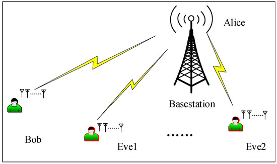
Figure 1.
System model.
If image signals were sent without any protection, both Bob and Eve could recover the same information, which resulted in information leakage. To overcome the problem, the PPF-OM scheme was proposed to enhance information security and eliminate the PDL at the same time, and this is detailed in the following sections.
3. Signal Model and Problem Description
The k-th transmit image signal can be represented, as in [4]:
where is the PS and is the polarized angle. denotes the auxiliary polarized angle. denotes the k-th amplitude-phase modulation (AM) symbol, where and denote the amplitude and phase, respectively.
For receivers, the k-th received image signal was denoted, as follows:
where is the noise vector with the probability density function (PDF) as .
If the receivers have the PSs, then the AM signal could be obtained through polarization matching, as follows:
Next, the maximum likelihood estimate (MLE) was used to demodulate the AM image signal.
If receivers did not know the PSs, the blind demodulation method was applied, as follows:
- Based on the k-th received image signal, the PS was obtained, as follows:
- With , the polarization matching was carried out according to the k-th received signal, such as in Equation (3), as follows:
In this manner, the information carried by AM signals could also be recovered by MLE. Thus, if the signals were broadcast without protection, it was possible for Eve to overhear on the information.
However, we considered a polarimetric multi-tap fading channel, where the transfer function for each channel estimation was written according to [21]:
where and are the number of the multipaths associated with horizontal (H) polarization and vertical (V) polarization, respectively; () denotes the propagation delay associated with the i-th propagation path for the H (V)-polarized component; f denotes the frequency; and denotes the i-th complex channel gain between the X-polarized transmission antenna and the Y-polarized receiver antenna. For other types of channels, the analysis method was the same.
As H was always non-ideal due to the complex propagation environment and the limited XPD of the dual-polarized antennas on the receiver side, the channel coefficient H was written, as follows:
where denote eigenvalues. and are unitary matrices. Therefore, a non-ideal channel state has a negative influence on signal demodulation, and this effect is called polarization dependent loss (PDL), which was measured by , (λ1 ≥ λ2).
Then, the k-th receiver signal was written, as follows:
The non-ideal H led to interference J in the received signals, which further affected the polarization matching, as shown in Equation (5), and led to BER performance degradation.
Fortunately, based on the interoperability of the wireless channel, both the transmitter and receivers could acquire the channel transfer function H. Therefore, the pre-compensation method on the transmitter side or the zero-forcing method at the receiver side could be utilized to relieve the PDL [4]. However, the PDL could not be fully eliminated by these two methods. For resolving the PDL and enhancing the transmission security, the PPF-OM scheme was proposed, as described in the following sections.
4. The Principle of the PPF-OM Scheme
4.1. Signal Processing on the Transmitter Side
In the PPF-OM scheme, the information sequence was divided into two parts, and , which were translated into AM symbols with the variable L, as shown in Figure 2.
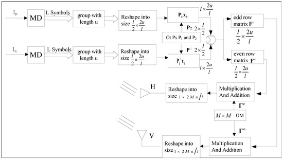
Figure 2.
Diagram of the signal processing on the transmitter side.
We assumed the length of a signal block was u, and the symbols were divided into groups. Here, we used the first-part signal as an example and chose one group as an example (for the other groups, the analysis was the same). The symbol vector is written as
Then, X was reshaped into a matrix with the size , as follows:
In the same way, the second-part signal Y was reshaped into with the size , which had the same expression as Equation (10).
For the first matrix, each row was multiplied with a PS from the PS matrix P, with the same index, to obtain the following:
For the second matrix, each row was multiplied with a PS from the PS matrix and with the same index, where the corresponding PSs of P and were orthogonal to each other, e.g., . Thus, we obtained .
Afterwards, we assumed , and the odd and even rows of were denoted by and , respectively, as follows:
Then, a size () orthogonal matrix was created with column vectors that were orthogonal to each other. The first columns of were denoted by , and the other columns of were denoted by . Then, each column vector of was multiplied by each row of , which resulted in the following:
It was found that and were the matrix, which had to be reshaped into vectors and for transmission by two orthogonal polarized antennas, respectively.
4.2. Signal Processing on the Receiver Side
For Bob, signal demodulation procedures are shown in Figure 3.
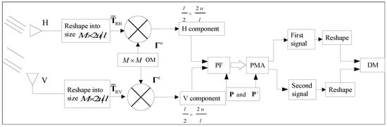
Figure 3.
Signal processing on the receiver side.
The received signal vectors were written, as follows:
where and are noise vectors. To simplify the formula analysis, the noise were ignored temporarily. and should first be reshaped into the matrix, which was written, as follows:
According to Equation (15), interferences and were found in the received signals. To remove the interferences, the orthogonal matrix was used to process the received signals:
where the superscript H denotes the conjugate inversion. Then, we used the k-th row of as an example, according to the orthogonality of the vectors of , and we obtained the following:
According to the interoperability of the wireless channels, both Alice and Bob obtained the channel state information (CSI); thus, the impact of the CSI on was eliminated. In addition, as column vectors of were not the same, according to Equation (17), each row vector could be separately recovered. Thus, we obtained the following:
In this manner, interferences for both polarization signals were eliminated. As in Equation (12), both and resulted from the addition of two signals, which would be separated for demodulation. Here, the corresponding rows of and were transformed into pairs for polarization filtering. The k-th pair was taken as an example, which could be written, as follows:
We assumed two PSs were and ; then, the polarization filtering matrices were calculated, as in [20]:
where I denotes the unit matrix and
Based on Equation (20), it was determined that
According to Equation (22), the noise power after being processed by polarization filtering matrices was calculated, as follows:
where is the principal angle between subspace and on Poincare sphere [26]. As and were both orthogonal to each other, and , the noise power was not amplified.
Based on Equation (22), two PSs were used to conduct the polarization matching to recover two signals, as follows:
From Equation (24), the k-th component of both two signals were obtained, and the other components were then obtained in the same manner. Therefore, the two signal matrices could be written, as follows:
Finally, two signals were demodulated based on the MLE rule.
On the transmitter side, the amount of computation was concentrated in Equations (11)–(13). Equation (11) required 2u penalty operations. Equation (12) required 2u addition operations, and Equation (13) required penalty operations and addition operations.
On the receiver side, the amount of computation was concentrated in Equations (16) and (22). Equation (16) required penalty operations and addition operations; Equation (22) required 4u penalty operations and 2u addition operations. Based on above analysis, we found that the amount of computation was proportional to u and M; thus, in real practice, we could adjust the parameters according to the actual calculation power of the communication equipment. In other words, the computational complexity was adaptable.
5. Security Performance Evaluation
In this section, the security performance of the PPF-OM scheme is evaluated. First, we assumed the eavesdropper Eve had no information of the parameters l, u, PSs P, , the orthogonal matrix, and the modulation mode of the two AM signals. Based on the demodulation procedures of Bob, if Eve attempted to recover the information, the first step would include reshaping the received signal vector into the matrix.
- It was known that the length of the received image signal vector was , and if the number of the divisor of was , there were at least matrix reconstruction methods. In addition, was adjustable and would increase as increased. Moreover, the reshaped matrices and were composite matrices, and the orthogonal matrix was also unknown, which made it difficult to determine the correct matrix size. When the size of the reshaped matrices and were incorrect, it was not possible to correctly recover the horizontal and vertical signal component matrices.
- If Eve could correctly reshape the received image signal vector into a matrix, Eve would know and were composite matrices that should be processed by in the correct order. As Eve did not have the information about , it needed to search for the correct and order, as follows:According to Equation (26), only obtained . In other cases, H and V components could not be correctly recovered, nor could the two signals be separated through polarization filtering. In addition, a larger M led to a larger amount of calculation for Eve. Therefore, in this case, the parameters were difficult to determine.
- If we assumed that Eve could correctly obtain the matrices and while the information regarding PSs was used for processing, the transmission signals were unknown. As and were mixed matrices of two polarized signals, the first step was to isolate them for demodulation. Thus, Eve must first search for the correct PSs to construct polarization filtering matrices for the signal separation. However, the PSs for each row signal vector were different, and the modulation mode of the two AM signals was unknown. Therefore, even with the right polarization filtering matrices, it would be difficult to determine the correct AM signals. Based on the above analysis, it was difficult to avoid errors in the PSs. In this condition, the PF matrices of Eve were written, as follows:where and denote the errors. Here, we assumed , and the signal separation of the k-th row signal vector was taken as an example:whereWe found , and after polarization matching, Equation (28) was written, as follows:In the same manner, we found the following:where .According to Equations (29) and (30), we found that there were interferences in recovered signals by Eve that would degrade BER performance. Thus, for Bob and Eve, the signal-to-noise ratio (SNR) was calculated as:Then, the average secrecy rate with the proposed scheme could be calculated, as follows:As analyzed in Equation (31), we found and ; thus, would always be positive when deviations existed in any of the parameters mention above, which ensured transmission security.
6. Numerical Result
In this section, a sampling of simulation results by MATLAB are provided and analyzed to show the validity and security performance of the proposed method. In the simulations, the XPD of the environment and the dual-polarized antennas were both set at 15 dB, and the information sequence was divided into two parts. Each part was translated into AM symbols. In addition, 90% of the signal power was transmitted through the line-of-sight channel while 10% was transmitted through the non-line-of-sight channel. The CSI was updated every 200 symbol periods: u = 200 and l = 10; M = 10.
In this simulation, the validity of the proposed scheme was evaluated through BER performance. At first, two image information sequences were modulated into symbols using the pulse-amplified-modulation (PAM) technique, and the BER curves were plotted in Figure 4. Furthermore, 4PAM and 8PAM were used for the signal modulation of the two information sequences. We found the BER performances of both the 8PAM and 4PAM signals approached the theoretical value, which was calculated according to the ideal Gaussian channel (the CSI matrix was a unit matrix). This was because based on the PPF-OM scheme, the PDL was naturally eliminated, and there was no mutual interference between orthogonal polarizations. In addition, the noise power was not amplified. Thus, the two signals could be separately demodulated.
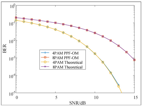
Figure 4.
BER performance of PPF-OM (PAM).
Next, 4PAM and 8PAM were replaced by 4PSK and 8PSK, respectively, and the BER curves are shown in Figure 5. We found that the BER curves approached the theoretical ones, which had the same results as the PAM technique.
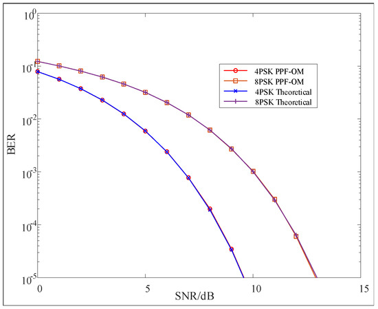
Figure 5.
BER performance of PPF-OM (PSK).
Furthermore, we utilized 4QAM and 16QAM to modulate the two information sequences, and the BER curves are shown in Figure 6. The two BER curves approached the theoretical ones. Overall, regardless of the modulation techniques used in the PPF-OM scheme, the two signals could be demodulated without interference and approach theoretical values. The simulations demonstrated the validity of the proposed scheme for eliminating the PDL, which was consistent with the theoretical derivations.
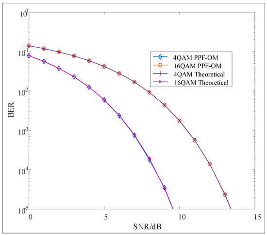
Figure 6.
BER performance of PPF-OM (PSK).
In this simulation, the security performance of the PPF-OM scheme was evaluated in terms of the BER performance when there were errors in the orthogonal matrix. Here, we assumed Eve could correctly reshape the matrix into the matrix and knew M = 10 as well as the PSs that had been used to process the two image signal vectors. However, Eve did not know the correct orthogonal matrix. Both 4PSK and 8PSK were utilized to modulate two information sequences, which yielded the 4PSK and 8PSK symbols, respectively. Figure 7 shows the plots of the BER curves when there were errors in the orthogonal matrix. In the simulation, we add the error to all the elements in the orthogonal matrix. We found that when the error was 0.1, the BER performance deteriorated significantly, and when the error grew larger, almost no information could be correctly recovered. In addition, with the PPF-OM scheme, it was difficult for Eve to decipher the orthogonal matrix for the signal matrices, as after being processed by the OM, they were composite matrices, which made it difficult to determine the correct OM. Thus, the information security was enhanced.
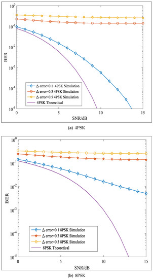
Figure 7.
BER performance of the PPF-OM scheme with errors in OM.
In this simulation, the security performance of the PPF-OM scheme was evaluated in terms of the BER performance when there were errors in the PSs. Both 4PSK and 8PSK were utilized to modulate the two information sequences, which yielded the 4PSK and 8PSK symbols, respectively. Here, the errors were added to the polarization parameter while th other parameters were distortionless. The BER curves of 4PSK and 8PSK with are shown in Figure 8. We found that a larger error in would led to a worse BER. In addition, if there were errors in both parameters and , the BER performances worsened, as shown in Figure 9, where the BER curves with are plotted. If there were errors in both parameters, the BER performance would be worse than that shown in Figure 8. Moreover, larger errors in both and would lead to worsening BER performances. As analyzed in Section 5, for Eve, the polarization parameters were difficult to obtain, and the modulation techniques were unknown; therefore, the errors in polarization parameters were inevitable. Therefore, in this case, the BER performance of Eve would be worse.
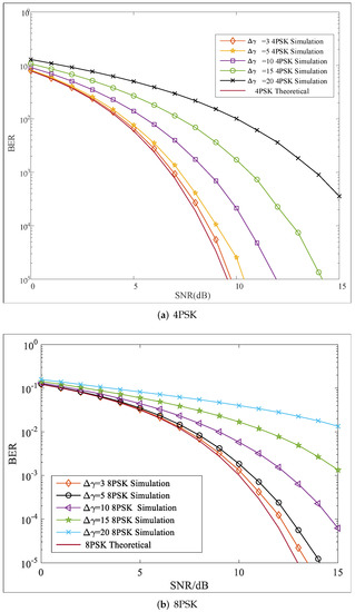
Figure 8.
BER performance with PS errors ().
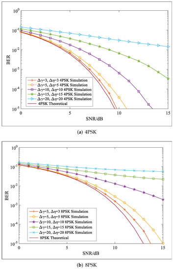
Figure 9.
BER performance with PS errors .
In this simulation, the security performance was evaluated in terms of the average secrecy rate (ASR). Both 4PSK and 8PSK were utilized to modulate the two information sequences, which yielded the 4PSK and 8PSK symbols, respectively. We assumed Eve could correctly reshape the received signal vectors into the matrices and as well as obtain the matrices correctly. However, the PSs that had been used to process the signals were unknown. As analyzed in Section 5, the PSs were difficult to obtain, and when there were errors in PSs, based on Equations (29) and (30), there would be interferences in the recovered signals. Therefore, the ASR was improved, as shown in Figure 10, where the ASR curves are plotted. Here, the errors were added only to the polarization parameter while the other parameters were distortionless. When the error was zero, the ASR equaled zero and did not change with the SNR. In addition, when the error was non-zero, the ASR increased alongside the SNR, and the larger error in led to a larger ASR. These simulation results were consistent with the theoretical derivation process. Therefore, with the PPF-OM scheme, a positive ASR was ensured, and the transmission security was enhanced.
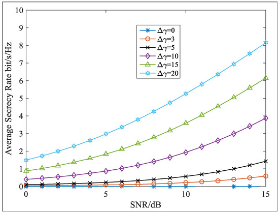
Figure 10.
Average secrecy rate versus SNR with errors in .
7. Conclusions
The PPF-OM scheme proposed in this paper both ensured the transmission security and eliminated the PDL. For eavesdroppers, the related parameters used to recover the signals were difficult to decipher, and thus, the BER performance was degraded. In addition, the errors in these parameters led to self-interference in Eve’s received signals. Therefore, the signal-to-noise ratio decreased, and the average secrecy rate became a positive value. In this manner, the transmission security was enhanced. The PPF-OM scheme is a signal processing technology that can adapt to most current communication systems. In the next step, we further consider simplifying signal processing on the basis of guaranteeing performance.
Author Contributions
Methodology, Z.P. and C.Y.; Formal analysis, Z.L. (Zhengjun Liu); Investigation, Z.L. (Zhangkai Luo), Z.P., C.Y., Z.L. (Zhengjun Liu) and H.C.; Resources, Z.P.; Writing—original draft, Z.L. (Zhangkai Luo). All authors have read and agreed to the published version of the manuscript.
Funding
This work was supported by the Laboratory Basic Research Program (DXZT-JC-ZZ-2020-003) and the National Natural Science Foundation of China (Grant 62005320, 61975044).
Conflicts of Interest
The authors declare no conflict of interest.
References
- Hajiyat, Z.; Ismail, A.; Sali, A.; Hamidon, M.N. Antenna in 6G Wireless Communication System: Specifications, Challenges, and Research Directions. Optik 2021, 231, 166415. [Google Scholar] [CrossRef]
- Li, Q.; Xu, D. Secure Transmission in Multicarrier Power-Splitting Wireless Powered Communication Networks with Full-duplex Receivers. In Proceedings of the 2019 IEEE 19th International Conference on Communication Technology (ICCT), Xi’an, China, 16–19 October 2019; pp. 1355–1359. [Google Scholar] [CrossRef]
- Da, X.; Liang, Y.; Hu, H.; Xu, R.; Ni, L.; Zhai, D.; Pan, Y. Embedding WFRFT Signals Into TDCS for Secure Communications. IEEE Access 2018, 6, 54938–54951. [Google Scholar] [CrossRef]
- Luo, Z.; Wang, H.; Zhou, K.; Lv, W. Combined Constellation Rotation With Weighted FRFT for Secure Transmission in Polarization Modulation Based Dual-Polarized Satellite Communications. IEEE Access 2017, 5, 27061–27073. [Google Scholar] [CrossRef]
- Fang, X.; Sha, X.; Li, Y. MP-WFRFT and constellation scrambling based physical layer security system. China Commun. 2016, 13, 138–145. Available online: http://xueshu.baidu.com/s?wd=paperuri (accessed on 9 February 2023).
- Valliappan, N.; Lozano, A.; Heath, R.W. Antenna Subset Modulation for Secure Millimeter-Wave Wireless Communication. IEEE Trans. Commun. 2013, 61, 3231–3245. [Google Scholar] [CrossRef]
- Wang, S.; Wei, L.; Jing, L. Physical-Layer Encryption in Massive MIMO Systems with Spatial Modulation. China Commun. 2018, 15, 159–171. [Google Scholar] [CrossRef]
- Wang, Z.; Chen, F.; Qiu, W.; Chen, S.; Ren, D. A two layer chaotic encryption scheme of secure image transmission for DCT precoded OFDM-VLC transmission. Opt. Commun. 2018, 410, 94–101. [Google Scholar] [CrossRef]
- Xie, T.; Zhu, J.; Li, Y. Artificial-Noise-Aided Zero-Forcing Synthesis Approach for Secure Multi-Beam Directional Modulation. IEEE Commun. Lett. 2018, 22, 276–279. [Google Scholar] [CrossRef]
- Wang, Q. Defending wireless communication against eavesdropping attacks using secret spreading codes and artificial interference. Comput. Secur. 2021, 103, 102175. [Google Scholar] [CrossRef]
- Cho, S.; Chen, G.; Coon, J.P. Zero-Forcing Beamforming for Active and Passive Eavesdropper Mitigation in Visible Light Communication Systems. IEEE Trans. Inf. Forensics Secur. 2021, 16, 1495–1505. [Google Scholar] [CrossRef]
- Shu, F.; Wu, X.; Li, J.; Chen, R.; Vucetic, B. Robust Synthesis Scheme for Secure Multi-Beam Directional Modulation in Broadcasting Systems. IEEE Access 2016, 4, 6614–6623. [Google Scholar] [CrossRef]
- Yaacoub, E.; Al-Husseini, M. Achieving physical layer security with massive MIMO beamforming. In Proceedings of the 2017 11th European Conference on Antennas and Propagation (EUCAP), Paris, France, 19–24 March 2017; pp. 1753–1757. [Google Scholar]
- Moualeu, J.M.; Ngatched, T.M.N. Physical-Layer Security Enhancement via Relay-Aided D2D Communications Underlaying Cellular Networks. IEEE Open J. Commun. Soc. 2020, 1, 413–427. [Google Scholar] [CrossRef]
- Ray, P.P. A perspective on 6G: Requirement, technology, enablers, challenges and future road map. J. Syst. Archit. 2021, 118, 102180. [Google Scholar] [CrossRef]
- Zhu, J.; Yang, P.; Xiao, Y.; Di Renzo, M.; Li, S. Dual Polarized Spatial Modulation for Land Mobile Satellite Communications. In Proceedings of the 2018 IEEE Globecom Workshops (GC Wkshps), Abu Dhabi, United Arab Emirates, 9–13 December 2018; pp. 1–6. [Google Scholar] [CrossRef]
- Liu, F.; Wang, X.; Li, R.; Wang, B. Multilevel Continuous Polarization Modulation With High Spectral Efficiency in the Depolarization Channels. IEEE Access 2018, 6, 33002–33014. [Google Scholar] [CrossRef]
- Sun, D.; Zhang, Q.; Wei, D.; Zhang, M. A Secure Constellation Design for Polarized Modulation in Wireless Communications. IEEE Access 2020, 8, 130588–130597. [Google Scholar] [CrossRef]
- Wei, D.; Feng, C.; Guo, C.; Liu, F. A Power Amplifier Energy Efficient Polarization Modulation Scheme Based on the Optimal Pre-Compensation. IEEE Commun. Lett. 2013, 17, 513–516. [Google Scholar] [CrossRef]
- Luo, Z.; Wang, H.; Zhou, K. Physical Layer Security Scheme Based on Polarization Modulation and WFRFT Processing for Dual-polarized Satellite Systems. KSII Trans. Internet Inf. Syst. 2017, 11, 5610–5624. [Google Scholar] [CrossRef]
- Wei, D.; Liang, L.; Zhang, M.; Qiao, R.; Huang, W. A Polarization state Modulation based Physical Layer Security scheme for Wireless Communications. In Proceedings of the MILCOM 2016—2016 IEEE Military Communications Conference, Baltimore, MD, USA, 1–3 November 2016; pp. 1195–1201. [Google Scholar] [CrossRef]
- Luo, Z.K.; Pei, Z.M.; Zou, B. Polarization Filtering Based Transmission Scheme for Wireless Communications. IEICE Trans. Fundam. Electron. Commun. Comput. Sci. 2019, E102-A, 1387–1392. [Google Scholar] [CrossRef]
- Zhang, X.; Zhang, B.; Guo, D. Physical Layer Secure Transmission Based on Fast Dual Polarization Hopping in Fixed Satellite Communication. IEEE Access 2017, 5, 11782–11790. [Google Scholar] [CrossRef]
- Luo, Z.; Wang, H.; Zhou, K. Polarization Filtering Based Physical-Layer Secure Transmission Scheme for Dual-Polarized Satellite Communication. IEEE Access 2017, 5, 24706–24715. [Google Scholar] [CrossRef]
- Luo, Z.; Pei, Z. Orthogonal vector based transmission method for security enhancement and PDL elimination in dual-polarized wireless communications. Signal Process. 2022, 196, 108477. [Google Scholar] [CrossRef]
- Wen, Z.; Chunyan, F.; Fangfang, L.; Caili, G. Polarization oblique projection based self-interference cancellation against PA nonlinear distortion in MIMO full duplex system. China Commun. 2016, 13, 49–59. [Google Scholar] [CrossRef]
Disclaimer/Publisher’s Note: The statements, opinions and data contained in all publications are solely those of the individual author(s) and contributor(s) and not of MDPI and/or the editor(s). MDPI and/or the editor(s) disclaim responsibility for any injury to people or property resulting from any ideas, methods, instructions or products referred to in the content. |
© 2023 by the authors. Licensee MDPI, Basel, Switzerland. This article is an open access article distributed under the terms and conditions of the Creative Commons Attribution (CC BY) license (https://creativecommons.org/licenses/by/4.0/).