Abstract
Analysis of the vibration reduction characteristics of shock absorbers is crucial for engines. In this study, the fractal theory was applied to the contact surface of an under-platform damper (UPD), and the influence of the excitation force in the same and opposite directions on the roughness of the contact surface was studied. First, based on fractal geometry theory (FGT), the roughness characterization method of a UPD contact surface was proposed. Then, the friction mechanical model of the rough contact surface was established by combining it with a 3D contact mechanical model. Furthermore, a finite element dynamic model of a blade with a UPD structure was set up. Next, the harmonic balance method was used to calculate the nonlinear response characteristics of a blade under different levels of contact surface roughness. Finally, the influence of the contact surface roughness on the vibration reduction ability of a UPD under different excitation modes was analyzed. According to the simulation results, as the contact surface became rougher, the vibration suppression ability of the UPD on the blade became stronger and stronger. With the change in the centrifugal force of the UPD and the amplitude of the same/reverse excitation force, the influencing law of the contact surface roughness on the vibration suppression ability of the UPD remained unchanged, indicating that the rougher the contact surface roughness, the better the vibration suppression effect.
1. Introduction
In modern aviation aeroengines, fatigue fracture of the blades caused by vibration is one of the key problems that affect engine reliability. Dry friction damping structures have been widely applied in aeroengines due to their obvious vibration reduction effect, simple structure, and high reliability. Common dry friction damping structures consist of intermediate shrouded blades and under-platform dampers (UPDs) [1]. Generally speaking, UPDs are applied to the vibration reduction design of fan blades and turbine blades because of their advantages of a small additional centrifugal load and no adverse effect on the aerodynamic performance. Examples include the fan blades of the CFM56-3 and Taihang engines, and the high-pressure turbine blades of the JT9D, CF6, RB211, BR715, and AJI-31 engines. Studying the contact mechanical properties of asperities on rough surfaces can not only play a necessary guiding role in the vibration reduction characteristics of aeroengine blades with an under-platform damper structure, but it can also help improve the service life of aeroengines and enhance the reliability and safety of aeroengines during operation.
Great efforts have been made in the academic community to accurately describe the mechanical vibration characteristics of the real contact surface of a blade with an under-platform damper. For the contact surfaces of different under-platform dampers, the initial models used were finite element models [2,3] or half-space models [4,5], both of which have their advantages and disadvantages. The advantage of the spatial model is that the calculation efficiency is greatly improved, but the description of the elastic–plastic deformation is inaccurate. Therefore, a characterization method of complex contact surface roughness on account of the FGT is established in this paper.
The primary task for studying under-platform dampers is to quantitatively characterize the mechanical properties of the contact surface. Most early studies have used the macro-slip model, which assumes that the deformation and pressure on the contact surface are evenly distributed and that the contact surfaces enter the stick or slip state simultaneously. The representative work consists of the coupled double contact surface model proposed by Yang [6], the small degree of freedom theoretical model established by Sanliturk [7], and the B-G simplified model adopted by Hao Yanping. It is worth noting that the fretting sliding model can better describe the local slip phenomenon between the contact surfaces and predict the mechanical properties of the contact surface more accurately [8]. For example, Sanliturk et al. used multiple contact pairs in parallel form to establish a micro-slip model, and Panning [9] performed a micro-slip model comparative analysis of the damping effect of a wedge-shaped under-platform damper and a cylindrical under-platform damper. Additionally, Petrov [10] analyzed the vibration reduction effect of different damping structures using a self-developed dry friction nonlinear vibration response solving program.
In the early studies of dry friction structures, the contact interface was usually described by the macroscopic slip model. The smooth and flat surface of the part at the macroscopic angle shows different degrees of roughness and unevenness under the microscope, making the real area of contact during the vibration process smaller than the theoretical area [11]. With this model, a large load is distributed on the small contact area of the UPD, which aggravates its wear failure. First, the deformation of the interface and the uniform arrangement of the interface pressure are assumed. Then, the friction characteristics on the contact surface are described by the single-point Coulomb friction model. The advantages of this model include simplicity, intuition, and less computation, making the macroscopic slip model widely applied in early studies. In the actual structure, due to the influence of structural stiffness, contact surface coordination, and other factors, the contact surface is usually nonuniform contact and may appear in various contact states. Thus, the macroscopic slip model can only accurately represent the situation in which all nodes of the contact surface slip or stick simultaneously, which results in a large error compared to the actual situation. In 1967, Iwan [12] first constructed a micro-slip model to represent the contact state of the interface by parallel and series connections of multiple single-point Coulomb friction models. The micro-slip model is suitable for structures with large contact areas and complex contact states and can consider the complex contact state of different contact nodes. The existing dry friction structures that consider the micro-slip effect tend to be described by the micro-slip model.
Given that the energy dissipation of the contact nonlinear structure is obtained by the relative motion between the vibrating bodies, the dynamic characteristics of the structure are closely related to the mutual motion form of the contact interface. Aiming at the nonlinear phenomenon caused by the friction behavior of the contact interface, a suitable contact kinematics model was established. The contact kinematics models are mainly divided into four types: the 2D constant pressure dry friction model, the 2D constant allowable variable pressure dry friction model, the 3D constant pressure dry friction model, and the 3D constant allowable variable pressure dry friction model.
As confirmed by scholars in this field, the contact problem of rough surfaces will greatly affect the static and dynamic performance of mechanical structures, and the joint surface generated by the contact between two surfaces will make the performance of the whole mechanical equipment nonlinear, which leads to complicated problems. It is of great significance to apply scientific and effective research methods to the contact problem of surfaces. With the development of theory and practice, the contact theory of rough surfaces has been constantly improved. The German physicist Hertz first investigated the contact problem. In 1882, he published an article titled On the Contact of Elastic Solids, laying a foundation for the development of contact mechanics. Hertz mainly studied the normal displacement caused by the contact between two spheres and the problem of determining the contact area. Based on the following assumptions, a contact model of the elastic deformation of a sphere was established: (1) surfaces are continuous and nonconforming; (2) strains are small and within the elastic limit; (3) each solid can be considered as an elastic half-space; (4) surfaces are frictionless. Since then, lots of scientists have tried to use Hertz’s theory to study the contact mechanics of rough interfaces. Specifically, statistical modeling and analysis, research based on fractal geometry theory, finite element numerical solution, and experimental analysis have mainly been adopted.
In a search of the literature, it was found that there has been a lack of research on the influence of roughness on UPDs under different excitation methods. Therefore, the following work was carried out in this paper. Based on the friction characterization method of the complex dry friction contact surfaces, the influence of contact surface roughness on UPD vibration reduction under different excitation modes was studied. First, a finite element model with a UPD was established, and dynamic modeling of the under-platform damper was carried out in combination with the 3D dry friction model. Second, based on FGT, a characterization method of complex contact force considering the contact surface roughness was proposed for the contact surface between the UPD and the blade. Notably, this characterization method simulates the morphology of the rough interface and integrates Hertz theory to obtain the contact stiffness of the UPD contact interface and establish a contact mechanics model considering the roughness characteristics of the UPD contact interface. The contact stiffness of the interface was determined using a combination of Hertz theory and FGT. Moreover, the relevant parameters of the whole contact surface were obtained. Then, the dynamic model was combined with the contact mechanics model considering the roughness of the contact surface, and the dynamic response was calculated by the harmonic balance method. Finally, the vibration reduction characteristics of the different roughness parameters were analyzed based on the dynamic calculation results of different excitation modes. The fractal dimension D determines the contribution of the high- and low-frequency components in the surface profile. The fractal roughness G refers to a height-scaling parameter independent of the frequency [13].
2. Dynamic Modeling
After the finite element model of a blade with an under-platform damper was obtained, the point-to-point contact element of the contact surface was established. In order to reduce the calculation time, the degree of freedom of the blade with the UPD was reduced using the Craig–Bampton dynamic model reduction method, and the correctness of the reduced model was verified to prepare for the dynamic response calculation.
2.1. Dynamic Modeling of a Blade with an Under-Platform Damper
Since this UPD model has been applied in many studies, it is used for related research [14,15,16,17,18]. The blade and UPD are connected by mutual friction between the contact surfaces. During the vibration process, the blade with the UPD could be equivalent to a complete system. A simplified blade model with an under-platform damper is shown in Figure 1. It consists of two simplified blades connected by a UPD. The model includes two blades consisting of 3120 hexahedral units and a UPD consisting of 240 hexahedral units. The force (FN) was applied at both ends below the UPD to simulate the centrifugal load so as to ensure contact between the UPD and the blade on both sides. The excitation point was located at the root of the blade (N1 point, N2 point), and the harmonic excitation Q(t) = Psin(ωt) was applied. When the excitation force was applied only at the N1 position, the blade response had two resonance peaks, which were in the same direction and had reverse vibrations. Therefore, dynamic analysis was carried out under different excitation forces by applying codirectional or reverse excitation forces at the N1 and N2 positions of the two blades. The response point was at the tip of the left blade (point A), and a fixed constraint was applied at the bottom of the two blades. Under the action of excitation force, the UPD and the blades on both sides moved relatively, and the dry friction effect occurred between the contact interfaces. The dimensions of the UPD were l = 28 mm in length and b = 6.5 mm in width, with a θ = 30° edge plate angle. The contact interface between the UPD and two blades was established with 110 pairs of point-to-point contact elements, and the contact elements used the 3D friction model of variable pressure. As presented in Figure 1, the purple point was the contact pair node on the UPD.
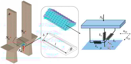
Figure 1.
A simplified blade model with an under-platform damper.
2.2. Model Reduction Method
First, Craig–Bampton dynamic reduction [19,20] was performed on the original model to obtain a reduced model. The selection of the 30-order modes ensured the correctness of the CB reduction. To be specific, the model size before and after the reduction was as follows:
As shown in Table 1, in comparison to the original model, the CB reduction reduced the model size by about 20 times. The frequency difference and modal assurance criterion (MAC) values of the first 10 orders before and after the model reduction are presented in Figure 2 and Table 2. Obviously, the frequency difference in the first 10 orders before and after the model reduction was less than 1/10,000, and the MAC values were close to 1, indicating that the dynamic characteristics of the model before and after the reduction were basically consistent with the original model.

Table 1.
Scale of simplified blade model with under-platform damper before and after reduction.
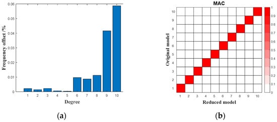
Figure 2.
Frequency difference and MAC value of simplified blade model with under-platform damper before and after reduction; (a) frequency difference; (b) MAC value.
Table 2.
Correlation data of simplified blade model with under-platform damper before and after CB reduction.
3. Characterization Method of Friction Force on Complex Dry Friction Contact Surface Based on Fractal Geometry Theory
Due to the centrifugal force, the UPD is closely connected to the blade to form a contact interface. At the same time, there are complex nonlinear phenomena in the contact interface. In order to study the influence of the nonlinear phenomena on the vibration reduction characteristics of the under-platform damper, a dry friction model was introduced, which applied variable pressure to simulate the contact state between the under-platform damper and the blade contact surface. On this basis, a complex contact model characterization method considering the surface roughness was proposed based on fractal geometry theory. This characterization method obtained the contact stiffness of the dry friction contact interface by simulating the morphology of the rough contact surface and combining it with Hertz contact theory so that a contact mechanics model considering the roughness characteristics was established.
3.1. Three-Dimensional Variable Positive Pressure Hysteresis Coulomb Friction Contact Model
The contact pressure changes with the movement of the contact pair and a three-dimensional variable positive pressure friction model are shown in Figure 3. N0 represents the normal initial positive pressure acting on the contact element; su(t) and sv(t) represent the displacements of the mass in two directions; ku and kv represent the shear spring stiffness in two directions, kn represents the normal spring stiffness; wu(t) and wv(t) represent the displacements of the friction damper in two directions; Qu and Qv represent the external excitations along the two directions, and Qn represents the normal external excitation. μ represents the friction coefficient between the contact surfaces.
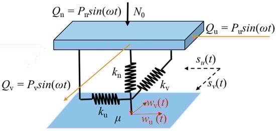
Figure 3.
Three-dimensional variable positive pressure friction model.
In this model, in view of the normal displacement of the mass block, pressure N is not constant. Therefore, N can be expressed as:
In the formula, n represents the distance of the normal motion of the mass block.
Since the normal action of the mass block has a simple harmonic excitation Qn, the normal displacement n(t) of the mass block will change harmonically, and its value also has positive and negative values. Therefore, when the normal displacement of the mass block is greater than −N0/kn, N0 may be greater than 0, and the contact surfaces make contact with each other; otherwise, the contact surfaces separate, and N0 is 0.
The friction force is judged in the same way as in the two-dimensional friction model, Hence, the total friction force generated by the mass block can be expressed as:
In the friction model shown in Figure 3, when the mass block is in contact with the plane, due to the existence of the shear springs ku and kv, the displacement of the friction device along the u and v directions is different. Then, the friction device in the plane produces the following four motions:
- (1)
- The velocity of the friction damper along the u and v directions is zero;
- (2)
- The velocity of the friction damper along the u direction is zero, and the velocity along the v direction is not zero;
- (3)
- The velocity of the friction damper along the v direction is zero, and the velocity along the u direction is not zero;
- (4)
- The velocity of the friction damper along the u and v directions is not zero.
In the above four motion conditions, when the speed of the friction damper along the u and v directions is zero, there is no relative motion between the contact pairs, and the mass block is in a stuck state. In the other three motion cases, the mass block is in a sliding state.
3.2. Simulation of Roughness Characteristics of Three-Dimensional Contact Surface Based on Fractal Geometry Theory
In this paper, the roughness of the contact surface was simulated by the Weierstrass–Mandelbrot (W–M) fractal function. The formula could be written as [21,22]:
The fractal dimension D determines the contribution of the high- and low-frequency components in the surface profile. The fractal roughness G represents a height-scaling parameter independent of the frequency. Therefore, the rougher the contact surface, the larger the fractal dimension, and the smaller the fractal roughness G.M was used to construct the overlapping ridge number of the surface profile. The frequency index of the complex contact surface is n. The assumed phase is Φm,n; γ is a fixed value, and is equal to 1.5 [22,23]. The different D fractal surfaces are presented in Figure 4.
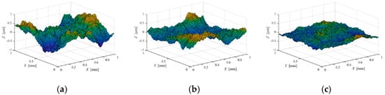
Figure 4.
Simulated fractal surface profiles under different three-dimensional fractal dimensions; (a) D = 2.2, G = 1 × 10⁻⁸; (b) D = 2.3, G = 1 × 10⁻⁸; (c) D = 2.49, G = 1 × 10⁻⁸.
3.3. Calculation Model of Contact Stiffness of Complex Contact Surface
According to related studies [23,24,25], the contact stiffness can be obtained by combining Hertz contact theory with the contact surface roughness. Based on the Young’s modulus (E1, E2) and Poisson’s ratio (v1, v2) of the contact surface between the under-platform damper and the blade, a plane equivalent system with a reduced elastic modulus is usually used to describe the complex contact surface of close contact:
The total contact load P and the actual contact area A can be obtained by the following two equations:
The asperity interference δ can be obtained by FGT.
where a′ = π(r′)2. Based on the Hertz contact theory, the elastic force is:
The normal and tangential contact stiffness are:
The contact stiffness of each contact pair can be expressed as:
where i denotes the number of contact pairs.
4. Nonlinear Dynamic Response Calculation Method
The harmonic balance method has some advantages, including clear physical meaning, strong applicability, and high computational efficiency. It is very suitable for the steady-state response calculation of strong nonlinear structures [26,27,28,29,30].
First, under the basic assumptions, the steady-state response displacement solution is obtained by a Fourier series:
where Nh represents the truncated harmonic order, ω represents the external excitation frequency, U0 represents the Fourier series corresponding to the ‘0’ order harmonic, and Uck and Usk represent the Fourier series corresponding to the k-order harmonic. In addition, Nd denotes the degree of freedom of the whole system, and the Fourier series vectors of dimension Nd·(2Nh + 1) are arranged as follows during the calculation:
Given that the nonlinear force and the external excitation force can also be expressed as the product of the transformation matrix and the corresponding Fourier coefficients,
Finally, an equilibrium equation of the multi-harmonic balance method with the Fourier coefficients as unknowns is obtained:
where P(ω) = ω2NM∇2 + ωNc∇ + NK represents the dynamic stiffness matrix, NM represents a block diagonal matrix consisting of a mass matrix M, NM = diag(M, M,⋯), and NC and NK have the same structure as NM. The algebraic equations can be solved using arc-length continuation [31] and the Newton–Raphson iterative method [32].
5. Vibration Response Analysis of Blade with Under-Platform Damper
As shown in Figure 5, in this study, different states of the engine were simulated using three different excitation modes. The relevant parameters of the blades are presented in Table 3. This section analyzes the influence of the fractal dimension D and the fractal roughness G on the blade contact surface state and the vibration reduction characteristics under different excitation forces and different centrifugal forces. Among them, the fractal dimension D determines the contribution of the high-and low-frequency components to the surface profile. The fractal roughness G is a height-scaling parameter independent of the frequency.
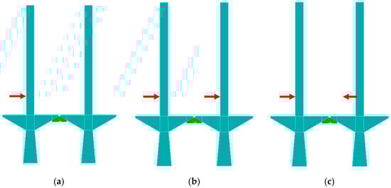
Figure 5.
Different excitation methods; (a) exciting force; (b) excitation forces in the same direction; (c) excitation forces in the opposite direction.
Table 3.
Default parameters of blade with under-platform damper structure.
5.1. Time Domain Signals of Co-Directional and Reverse Excitation Force
Taking the contact pair of UPD slices in Figure 6a as an example, in a complete vibration cycle, the influence of codirectional vibration and reverse vibration on the contact state was obtained under different levels of roughness. As shown in Figure 7 and Figure 8, under certain calculation conditions, different contact states of stick, slip, or separation at different times appeared on the contact surface. Therefore, different contact conditions can have different nonlinear phenomena.
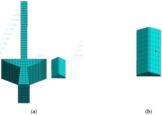
Figure 6.
Location of analysis; (a) contact node between UPD and blade; (b) UPD bilaterally symmetrical position.
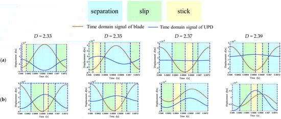
Figure 7.
Contact state between UPD and blade when the fractal dimension D changes; (a) excitation forces in the same direction; (b) excitation force in the opposite direction.
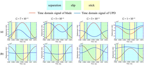
Figure 8.
Time domain signals with the fractal roughness parameter; (a) excitation forces in the same direction; (b) excitation force in the opposite direction.
The co-excitation force and the reverse excitation force had different effects on the vibration of the UPD, as shown in Figure 6b. The symmetrical nodes on both sides of the UPD were selected as the analysis objects to calculate the time-domain vibration signals. As shown in Figure 9, in the case of co-excitation and reverse excitation, there were vibrations of the UPD nodes on both sides in three directions. As can be seen, the movement of the UPD was translational when the excitation forces moved in the same direction, whereas the UPD produced torsional motion when the excitation forces moved in opposite directions.
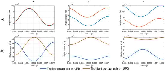
Figure 9.
Time domain signals; (a) excitation forces in the same direction; (b) excitation forces in the opposite directions.
5.2. Influence of the Contact Surface Roughness on the Contact State of the Contact Surface of the Under-Platform Damper
In this study, 110 contact pairs were established on the two contact surfaces of the blade–flange plate to describe the vibration of the entire contact surface (see Figure 10 and Figure 11). The motion of each contact pair under three excitation forces and different levels of roughness can be observed. The dots of different colors represent the nodes. To be specific, the blue indicates that the node was in a complete stick state, the green indicates that the node was in a stick–slip state, and the red indicates that the node was separated during the motion period but was still in a stick–slip state during contact. Additionally, a dry friction damping effect can be produced in the stick–slip state and the separation–stick–slip state.
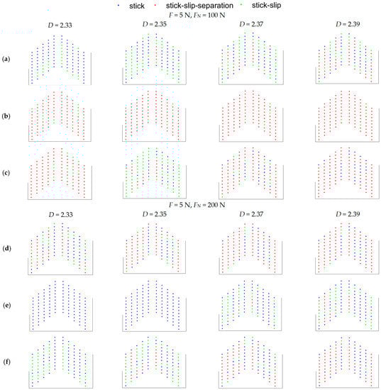
Figure 10.
Influence of the roughness fractal dimension D on the contact state: (a,d) single exciting force; (b,e) excitation forces in the same direction; (c,f) excitation forces in the opposite directions.
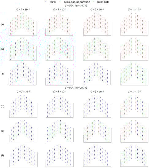
Figure 11.
Influence of the fractal roughness G on the contact state; (a,d) single exciting force; (b,e) excitation forces in the same direction; (c,f) excitation forces in the opposite directions.
It can be observed in Figure 8 and Figure 11 that in a complete vibration cycle, with the increase in the roughness of the contact surface, the roughness fractal dimension D increased, the fractal roughness G decreased, the nodes of the contact surface in the complete stick state declined, the stick–slip state and stick–slip–separation state nodes increased, and the nonlinearity of the system and the dry friction damping effect were strengthened. This study also compared the contact state of the contact surface under excitation forces of 5 N and 2 N. When the excitation force was large, there were fewer nodes in the complete stick state, and most of the nodes entered the slip state. At the same time, there were more nodes in the separation state. At this time, the system had obvious nonlinear characteristics, and the dry friction damping effect was also strong.
Within a certain range, as the contact surface became rough (D increased and G decreased), the number of nodes entering the slip state gradually increased, and the dry friction effect of the contact interface gradually strengthened, causing the vibration of the simplified blade model with the under-platform damper to have obvious nonlinear characteristics.
5.3. Influence of Contact Surface Roughness on Vibration Reduction Characteristics of Blades
5.3.1. Influence of D on the Vibration Reduction Characteristics of UPD
The vibration reduction characteristic curves of the different roughness fractal dimensions D of the contact surface under the three excitation conditions are shown in Figure 12. The exciting force is F and the centrifugal force of UPD is FN. Each curve corresponds to different fractal dimensions D. Under a single excitation force, there were two resonance peaks in the amplitude–frequency curve of the response point, and the blade vibration in the same direction generated a larger peak. With the application of the roughness formula, when the fractal dimension D was too large, the contact surface stiffness was large. The stiffness at this time did not conform to the real situation. Therefore, when the fractal dimension D was different, the blade resonance peak tended to move to the left, showing a nonlinear phenomenon. The reasons for this phenomenon are explained in Section 5.2. Furthermore, the resonance peak decreased with the increase in the D, and the reverse vibration peak of the blade was small and did not change much. In order to verify the vibration of two peaks when a single excitation force vibrated, the same-direction excitation forces and the reverse excitation forces were applied to the blade. With the increase in the D, the resonance peak of the blade decreased, and the change rule was the same as that of the single excitation force.
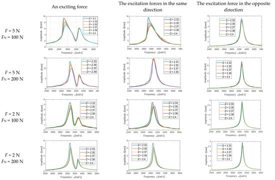
Figure 12.
Influence of roughness fractal dimension D on vibration reduction characteristics.
The dissipation energy changed with the roughness of the contact surface at different fractal dimensions D, as shown in Figure 13. Given that the whole contact surface was simulated by 110 contact pairs, the dissipated energy of the whole contact surface under a vibration period of the blade was obtained by analyzing each contact pair combined with the contact state in Section 5.1. In this study, when the excitation force was different or the centrifugal force was different, the dissipation energy increased with the increase in the D. However, when the single excitation force and the co-directional excitation force were applied, the phenomenon of first increasing and then decreasing occurred. Due to the fact that the contact surface was too rough, the contact state was in a complete stick state. Thus, there was no dissipation energy.
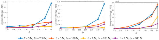
Figure 13.
Dissipation energy of fractal dimension D of different roughness.
5.3.2. Influence of G on the Vibration Reduction Characteristics of UPD
The influence of the G on the damping characteristics of the under-platform damper is presented in Figure 14, with each curve corresponding to different levels of G. The resonance peak of the blade decreased with the decrease in the G under different excitation forces, and the resonance peak of the blade also tended to move to the left, which was also a manifestation of nonlinear phenomena. As shown in Figure 15, the dissipation energy declined with the increase in the G of the contact surface, and different phenomena occurred when the reverse excitation force acted. The amplitude–frequency curve under the reverse excitation force reveals that the vibration amplitude was small at this time, and Figure 10 in Section 5.2 shows that the contact surface state under the reverse excitation force did not change significantly with the roughness parameter G and was almost in a complete stick state. Therefore, the dissipation energy was very small at this time, and the maximum value was 2.5 × 10⁻²¹ J, which can be ignored.
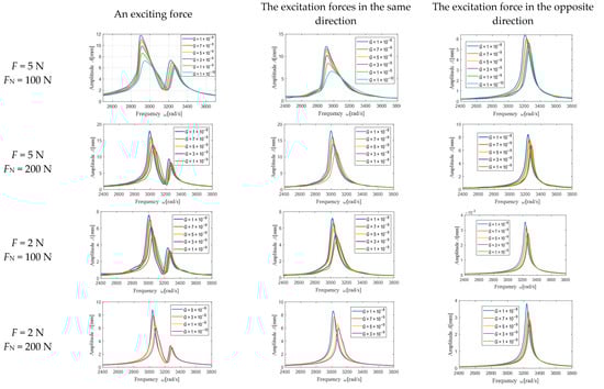
Figure 14.
Influence of the fractal roughness G on vibration reduction characteristics.
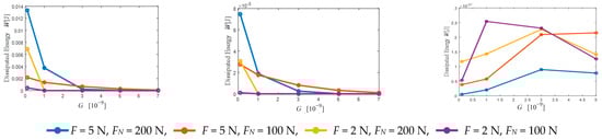
Figure 15.
Dissipative energy of different levels of fractal roughness G.
Within a certain range, as the contact surface became rough (increased D and decreased G), under different excitation forces or different centrifugal forces, the maximum response that corresponded to the resonance frequency decreased and the dissipation energy increased.
6. Conclusions
Based on the 3D dry friction model and fractal geometry theory, a friction mechanical model was established to represent the contact behavior of the rough contact surface of an under-platform damper. On this basis, a finite element dynamic model of a blade with an under-platform damper was established, and the finite element model was reduced to decrease the calculation time. Furthermore, the harmonic balance method was used to analyze the influence of the roughness level of the contact surface on the vibration reduction performance of the under-platform damper under different centrifugal forces, excitation amplitudes, and phases (in the same direction and opposite directions). The numerical analysis proves that:
- (1)
- Under excitation forces in the same direction, the UPD appeared to undergo translational motion, whereas under the opposite excitation force, rotation appeared. Under excitation forces in different directions, the contact state of the UPD between the blades appeared to have viscous slip separation at different times, which led to different nonlinear phenomena in the vibration process;
- (2)
- When the centrifugal force of the under-platform damper was small, there were more nodes on the contact surface of the under-platform damper, which led to a strong nonlinear phenomenon. With the increase in the centrifugal force, the contact nodes that were in a complete stick state gradually increased, while the nonlinear phenomena and vibration suppression performance weakened;
- (3)
- When the two blades were subjected to the same excitation force, there were more nodes in the slip state of the contact surface of the under-platform damper, which led to a strong nonlinear phenomenon, and the contact surface produced more dissipated energy. When the two blades were subjected to a single excitation force or a reverse excitation force, the contact nodes in a complete stick state increased, the nonlinear phenomenon weakened, the contact surface produced less dissipation energy, and the vibration suppression performance weakened.
- (4)
- The fractal dimension D determined the contribution of the high- and low-frequency components to the surface profile. Additionally, the fractal roughness G refers to a height-scaling parameter independent of the frequency. As the contact surface of the shock absorber under the platform became rougher, the D increased, whereas the G decreased. The number of nodes in the sliding state of the contact surface of the under-platform damper increased, which presents a strong nonlinear phenomenon. Moreover, the dissipation energy generated by the contact surface increased, the maximum response corresponding to the resonance frequency was reduced, and the vibration suppression performance was enhanced.
In order to study the influence of roughness on a UPD, a more general simplified model was adopted because the simplified model had the problem of a small structural angle. In a real engine, the damper may not roll or have liftoff at such a shallow vertex angle. Only one UPD angle was considered in this paper. The influence of different angles will be studied later. Therefore, it is essential to further study the selection of the UPD angle. During the rotation of the blade, there is wear between the blade and the under-platform damper. According to the wear evolution law of the contact surface, this characterization model can not only obtain the interface contact stiffness at different wear stages by changing the contact surface morphology and the pressure distribution of the contact surface, but it can also determine the contact force characterization of the complex dry friction contact interface considering the wear of the contact surface. Therefore, it is concluded that the wear and roughness characterization model can be combined for further study.
Author Contributions
Conceptualization, H.S. and S.H.; methodology, S.H.; validation, H.S., G.Y. and C.Z.; formal analysis, H.S.; investigation, H.S.; resources, S.H.; data curation, H.S.; writing—original draft preparation, H.S.; writing—review and editing, S.H.; visualization, C.L.; supervision, S.H.; project administration, S.H.; funding acquisition, S.H. All authors have read and agreed to the published version of the manuscript.
Funding
This research was funded by the National Natural Science Foundation of China (Nos. 52105104, 12072146), and the National Major Foundational Projects of Aeroengines and Gas Turbines (No. J2019-IV-0023-0091). The APC was funded by the National Natural Science Foundation of China (No. 52105104).
Data Availability Statement
Where no new data were created.
Conflicts of Interest
The authors declare no conflict of interest.
Nomenclature
| N0 | normal initial positive pressure |
| su(t), sv(t) | displacements of the mass in two directions |
| ku, kv | shear spring stiffness in two directions |
| kn | normal spring stiffness |
| wu(t), wv(t) | displacements of the friction damper in two directions |
| Qu and Qv | external excitations along two directions |
| Qn | normal external excitation |
| μ | friction coefficient |
| N | pressure |
| n | distance of the normal motion of the mass block |
| f | total friction force |
| D | fractal dimension |
| G | fractal roughness parameter |
| M | overlapping ridge number |
| Φm,n | assumed phase |
| γ | fixed value equal to 1.5 |
| E1, E2 | Young’s modulus |
| v1, v2 | Poisson’s ratio |
| P | total contact load |
| A | actual contact area |
| δ | asperity interference |
| ΔFe | elastic force |
| Kn, Kt | normal and tangential contact stiffness |
| kni, kti | stiffness of each contact pair |
| M, K, C | mass, stiffness, damping matrix |
| Nh | truncated harmonic order |
| ω | external excitation frequency |
| U0, Uck, Usk | Fourier series corresponding to the  -order harmonic -order harmonic |
| Nd | degree of freedom of the whole system |
| f(t) | nonlinear force |
| fnl | external excitation force |
| P(ω) | dynamic stiffness matrix |
Abbreviations
| UPD | under-platform damper |
| FGT | fractal geometry theory |
| CB | Craig–Bampton |
References
- Petrov, E.P.; Zachariadis, Z.I.; Beretta, A.; Elliott, R. A study of nonlinear vibrations in a frictionally damped turbine bladed disk with comprehensive modeling of aerodynamic effects. J. Eng. Gas Turbine Power 2013, 135, 032504. [Google Scholar] [CrossRef]
- Panagiotopoulos, P.D.; Panagouli, O.K.; Mistakidis, E.S. Fractal geometry in structures. Numerical methods for convex energy problems. Int. J. Solids Struct. 1994, 31, 2211–2228. [Google Scholar] [CrossRef]
- Komvopoulos, K. Finite Element Analysis of a Layered Elastic Solid in Normal Contact with a Rigid Surface. J. Tribol. 1988, 110, 477–485. [Google Scholar] [CrossRef]
- Willner, K. Elasto-Plastic Normal Contact of Three-Dimensional Fractal Surfaces Using Halfspace Theory. J. Tribol. 2004, 126, 28–33. [Google Scholar] [CrossRef]
- Streator, J.L. Dynamic contact of a rigid sphere with an elastic half-space: A numerical simulation. J. Tribol. 2003, 125, 25–32. [Google Scholar] [CrossRef]
- Yang, B.D.; Menq, C.H. Characterization of Contact Kinematics and Application to the Design of Wedge Dampers in Turbomachinery Blading: Part II—Prediction of Forced Response and Experimental Verification//Turbo Expo: Power for Land, Sea, and Air. Am. Soc. Mech. Eng. 1997, 78712, V004T14A008. [Google Scholar]
- Sanliturk, K.Y.; Ewins, D.J.; Stanbridge, A.B. Underplatform dampers for turbine blades: Theoretical modeling, analysis, and comparison with experimental data. J. Eng. Gas Turbine Power 2001, 123, 919–929. [Google Scholar] [CrossRef]
- Schwingshackl, C.W.; Petrov, E.P.; Ewins, D.J. Effects of contact interface parameters on vibration of turbine bladed disks with underplatform dampers. J. Eng. Gas Turbine Power 2012, 134, 032507. [Google Scholar] [CrossRef]
- Panning, L.; Sextro, W.; Popp, K. Spatial dynamics of tuned and mistuned bladed disks with cylindrical and wedge-shaped friction dampers. Int. J. Rotating Mach. 2003, 9, 219–228. [Google Scholar] [CrossRef]
- Petrov, E.P. Explicit finite element models of friction dampers in forced response analysis of bladed disks. J. Eng. Gas. Turbine Power 2008, 130, 022502. [Google Scholar] [CrossRef]
- Goerke, D.; Willner, K. Normal contact of fractal surfaces—Experimental and numerical investigations. Wear 2008, 264, 589–598. [Google Scholar] [CrossRef]
- Iwan, W.D. On a Class of Models for the yielding behavior of continuous and composite systems. Int. J. Appl. Mech. 1967, 34, 612–617. [Google Scholar] [CrossRef]
- Niu, C.; Chen, J.; Yang, F.; Liu, Q.; Lei, H.; Wu, Y.; Wu, Y.; Rong, M. Investigation of the electrical rolling contact degradation based on fractal theory. Eng. Fail. Anal. 2020, 113, 104559. [Google Scholar] [CrossRef]
- Pesaresi, L.; Salles, L.; Jones, A.; Green, J.S.; Schwingshackl, C.W. Modelling the nonlinear behaviour of an underplatform damper test rig for turbine applications. Mech. Syst. Signal Process. 2017, 85, 662–679. [Google Scholar] [CrossRef]
- Pesaresi, L.; Armand, J.; Schwingshackl, C.W.; Salles, L.; Wong, C. An advanced underplatform damper modelling approach based on a microslip contact model. J. Sound Vib. 2018, 436, 327–340. [Google Scholar] [CrossRef]
- Qu, Z.; Hu, D.; Chen, Z. Contact nonlinear analysis for the under-platform dampers of blade based on a frictional energy dissipation model. In Structures; Elsevier: Amsterdam, The Netherlands, 2021; Volume 30, pp. 146–155. [Google Scholar]
- He, S.; Jia, W.; Yang, Z.; He, B.; Zhao, J. Dynamics of a Turbine Blade with an Under-Platform Damper Considering the Bladed Disc’s Rotation. Appl. Sci. 2019, 9, 4181. [Google Scholar] [CrossRef]
- He, B.; Ouyang, H.; Ren, X.; He, S. Dynamic response of a simplified turbine blade model with under-platform dry friction dampers considering normal load variation. Appl. Sci. 2017, 7, 228. [Google Scholar] [CrossRef]
- Pařík, P.; Kim, J.-G.; Isoz, M.; Ahn, C.-U. A Parallel Approach of the Enhanced Craig–Bampton Method. Mathematics 2021, 9, 3278. [Google Scholar] [CrossRef]
- Borisenko, V.; Leoro, J.; Didenko, A. Main rotor blade modeling approaches comparison. Finite element and Craig-Bampton methods. J. Phys. Conf. Ser. 2021, 2131, 032096. [Google Scholar] [CrossRef]
- Kantar, E.; Hvidsten, S.; Mauseth, F.; Ildstad, E. A stochastic model for contact surfaces at polymer interfaces subjected to an electrical field. Tribol. Int. 2018, 127, 361–371. [Google Scholar] [CrossRef]
- Jiang, S.; Zheng, Y.; Zhu, H. A contact stiffness model of machined plane joint based on fractal geometry theory. J. Tribol. 2010, 132, 011401. [Google Scholar] [CrossRef]
- Liu, Y.; Shangguan, B.; Xu, Z. A friction contact stiffness model of fractal geometry in forced response analysis of a shrouded blade. Nonlinear Dyn. 2012, 70, 2247–2257. [Google Scholar] [CrossRef]
- Zhao, Z.; Yang, Y.; Han, H.; Ma, H.; Wang, H.; Li, Z. Meshing Characteristics of Spur Gears Considering Three-Dimensional Fractal Rough Surface Under Elastohydrodynamic Lubrication. Machines 2022, 10, 705. [Google Scholar] [CrossRef]
- Huangfu, Y.; Chen, K.; Ma, H.; Li, X.; Han, H.; Zhao, Z. An improved model for meshing characteristics analysis of spur gears considering fractal surface contact and friction. Mech. Mach. Theory 2021, 158, 104219. [Google Scholar]
- She, H.; Li, C.; Tang, Q.; Ma, H.; Wen, B. Computation and investigation of mode characteristics in nonlinear system with tuned/mistuned contact interface. Front. Mech. Eng. 2019, 15, 133–150. [Google Scholar] [CrossRef]
- Krack, M.; Gross, J. Harmonic Balance for Nonlinear Vibration Problems; Springer International Publishing: Cham, Switzerland, 2019. [Google Scholar] [CrossRef]
- Urabe, M. Galerkin’s Procedure for Nonlinear Periodic Systems; Wisconsin University Madison Mathematics Research Center: Madison, WI, USA, 1964. [Google Scholar]
- Cardona, A.; Coune, T.; Lerusse, A.; Geradin, M. A multiharmonic method for non-linear vibration analysis. Int. J. Numer. Methods Eng. 1994, 37, 1593–1608. [Google Scholar] [CrossRef]
- Pierre, C.; Ferri, A.A.; Dowell, E.H. Multi-harmonic analysis of dry friction damped systems using an incremental harmonic bal- 524 ance method. Int. J. Appl. Mech. 1985, 52, 958–964. [Google Scholar] [CrossRef]
- Chan, T.F.C.; Keller, H.B. Arc-length continuation and multigrid techniques for nonlinear elliptic eigenvalue problems. SISC 1982, 3, 173–194. [Google Scholar] [CrossRef]
- He, J.H. A modified Newton–Raphson method. Commun. Numer. Meth. Eng. 2004, 20, 801–805. [Google Scholar] [CrossRef]
Disclaimer/Publisher’s Note: The statements, opinions and data contained in all publications are solely those of the individual author(s) and contributor(s) and not of MDPI and/or the editor(s). MDPI and/or the editor(s) disclaim responsibility for any injury to people or property resulting from any ideas, methods, instructions or products referred to in the content. |
© 2023 by the authors. Licensee MDPI, Basel, Switzerland. This article is an open access article distributed under the terms and conditions of the Creative Commons Attribution (CC BY) license (https://creativecommons.org/licenses/by/4.0/).