Featured Application
The significant feature of Wi-Fi 6 and beyond generations is a beamforming technology that allows the antenna arrays in a router or a client device (such as a tablet) to send and receive information over Wi-Fi in a desired direction. Conventionally, this is achieved using the commercially available phase shifters connected to the antennas. In contrast to commercially available phase shifters, the proposed novel phase shifters do not require additional electronics biasing circuitry, thus saving space and reducing the burden of additional power requirements at the Wi-Fi router.
Abstract
A linear phased array antenna excited with a novel composite right/left-handed (CRLH) phase shifters structure is proposed. The phase of the conventional CRLH transmission line is controlled with magnetically aligned micron-sized particles embedded inside the unit cell of the CRLH transmission line. The cascading of unit cells produces the desired phase shifts for the main beam scanning of the linear antenna array operating at a 5.5 GHz center frequency for Wi-Fi 6 applications. The proposed phase shifter design has a very low insertion loss (0.5–2 dB), excellent matching characteristics with the antenna array (less than −10 dB) and a small phase error (1–2 degrees). A 1 × 4 linear patch antenna phased array operating at a 5.5 GHz center frequency of the Wi-Fi 6 band is simulated using the Method of Moments (MoM) simulator platform. Then, the array is driven with the proposed novel CRLH phase shifters for the main beam at broadside and the main beam steered at 15- and 30-degree scan angles toward the desired users. For experimental validation, multiple unit cells of the proposed phase shifters are fabricated, and the 1 × 4 patch antenna array is fed with these fabricated unit cells of the phase shifters. The phased array radiation patterns are measured using an in-house fully calibrated anechoic chamber and were compared with simulated phased array patterns. The measured phased array patterns are in good agreement with the simulated patterns. As compared with commercially available phase shifters, the proposed novel CRLH phase shifters do not need external complex biasing circuitry, which is a major advantage in space constraint limitations at the router side of multi-user MIMO-OFDM systems.
1. Introduction
The Wi-Fi 5 (IEEE 802.11ac) and Wi-Fi 6 (IEEE 802.11ax) technologies both operate the 5 GHz bands. The significant Wi-Fi 6 change is that an access point (AP) can supervise both downlink and uplink transmissions to multiple devices (or groups of devices) through the physical layer using the phased array beamforming technique [1]. As a result, there is a 20–25% increase in the data rate throughput to ensure a high quality of service for the Internet of Things (IoT) environments such as train stations, convention centers and sports arenas [2,3]. Beamforming is a technology that allows the antennas in the router or a client device (such as a tablet, smartphone and laptop) to focus information signals toward the intended users and nulls (signals not of interest) toward the interferers. In Wi-Fi 6 and beyond generations, in combination with multi-user MIMO (MU-MIMO) technologies, beamforming helps users obtain more secure connections that boost their data rates. Wi-Fi 6 with MU-MIMO uses multiple spatial data streams for simultaneous communication with multiple devices using array antennas [4,5,6]. The Wi-Fi Alliance (WFA) specifications for various Wi-Fi standards are given in Table 1. The spatial stream is the antenna of an access point (router). A large number of antennas indicates higher throughput of the entire system. Array antennas in communication systems are popular because of the ability to electronically scan the directive beam instead of mechanical slewing. The beam pattern is scanned toward the signal of interest (desired user) in angular space by dynamically adjusting the excitation phases. Such an array is referred to as a phased array [7]. The excitation phases in a phased array are achieved with commercially available phase shifters. However, achieving the desired phases with commercially available phase shifters requires external dc biasing circuitry. If the dc control circuitry is designed on the same layer as the phase shifters, then there is a probability of coupling between the RF signal and dc signals. Therefore, dc signals may interfere with the RF signal in the array, which can cause variations in the desired amplitudes and phases of the antenna elements in the array. This can cause a reduction in antenna/array gain, efficiency and possible distortions of the radiation patterns [8,9]. Another disadvantage of the commercially available phase shifters is their limitations of usage in flexible and conformal electronics applications as they cannot be made flexible/bend due to the discrete electronics components. Currently, active research work is in progress to design and develop flexible antennas, flexible phased array antennas and flexible phase shifters for conforming them on commercial Wi-Fi routers [10,11]. A very important aspect of the proposed phased array with integrated phase shifters is the future exploration of its beam coverage (enhancement feature in Wi-Fi 6) with the router system shell [10]. A conformal antenna based on graphene-assembled films has been explored in [11] by placing it on the surface of a commercial router. The proposed phased array antenna can be a potential candidate for exploring its advantages (such as space utilization and miniaturization) on Wi-Fi commercial routers. Therefore, this proposed work focusses on a linear patch phased array with integrated novel phase shifters, which is an initial step toward exploring its performance on a Wi-Fi 6 access point (router) in near future.

Table 1.
WFA (Wi-Fi Alliance) Wi-Fi standards with specs.
In the literature, active research work is in progress to design planar phase shifters for phased array applications. In [12,13,14,15], planar phase shifters based on INKJET printing of BST (barium strontium titanate) material for phased array applications are proposed. The BST material is filled inside the fingers spacing of conventional inter-digital capacitors (IDCs). The major drawback of these designs is the requirement of high tuning voltages (up to 200 V) to achieve the desired phase shifts. In [16,17], planar tunable phase shifters based on ferroelectric ceramics for phased array antenna are designed. The ceramic material is filled inside a conventional artificial composite right/left-handed (CRLH) printed transmission line to vary the permittivity of the filled material and, therefore, change the phase response of the CRLH transmission line. The complex fabrication process and requirement of applying an external dc field strength hinder its usage for space constraint and conformal phased array applications on Wi-Fi routers. The phased array antenna in [18] is based on a polymer composite-based artificial left-handed transmission line phase shifter. The dielectric constant of the composite material is varied to obtain the desired phase shifts for the main beam steering of the array. However, a separate dc bias network needs to be designed and printed along with the phase shifters. In [19,20,21,22], switching elements (PIN diodes, varactor diodes, reed switches, MEMS switches) are utilized for the phased array antennas. Their main disadvantages are the requirements of external dc power supplies, bonding wires and fabrication of additional mechanical components, which not only complicate the design but are also bulky. Most recently, novel magnetic particles of micron size [23] have been successfully utilized in various RF and microwave devices. A complete thorough characterization of these particles is mentioned in [24]. Their applications for reconfigurable antennas, RF switches and microwave filters are explored in [25,26,27].
This proposed research work explores the novel design of combining a unit cell conventional metamaterial printed CRLH transmission line [28] and micron-sized magnetic particles [23] as a phase shifter for phased array applications. We call the proposed printed CRLH transmission line with embedded micron-size particles design ‘P-CRLH’ and the resulting phase shifter a P-CRLH phase shifter. The qualitative and quantitative comparisons of the proposed P-CRLH phase shifter with those available in the literature are summarized in Table 2 and Table 3. The proposed P-CRLH phase shifter design has the following advantages over the phase shifters reported in the literature: (1) in contrast to commercially available phase shifters, the proposed P-CRLH phase shifter does not require external dc biasing control circuitry, (2) a 60% size reduction as compared to similarly published work in [29], (3) no need of interconnects and bonding wires for the proposed P-CRLH phase shifter as required in conventional MEMS/Reed switches and (4) no need to break the printed transmission line for the installation of the proposed P-CRLH phase shifter as otherwise required for PIN/varactor diodes installation in the circuit [30,31].
Table 2.
Qualitative comparison of the proposed work with selected existing techniques.
Table 3.
Quantitative comparison of the proposed work with selected existing techniques.
2. Novel Phase Shifter Design
The proposed novel phase shifter based on a standard composite right/left-handed transmission line (CRLH-TL) unit cell [28] is shown in Figure 1. The top layer consists of two symmetrical printed stubs with length and width . There are six inter-digital fingers each having length and width with spacing among the fingers. The phase constant of the CRLH-TL unit cell can be expressed as [28]:
where is the right-handed (RH) series inductance, is the RH shunt capacitance, is the left-handed (LH) shunt inductance and is the LH series capacitance. represents the parasitic inductance of the CRLH-TL introduced by current flowing through the transmission line and is the parasitic capacitance between the printed conductors on top of the substrate and the ground plane. is due to the inter-digital capacitors and is introduced due to the short-circuit stubs. The RF signal traveling through the CRLH transmission line unit cell will have a phase shift given by:
where is the physical length of the CRLH transmission line unit cell given in Figure 1. Two Magneto-static field Responsive Structures (MRSs) [32] are placed in the two symmetrical stubs to produce the effects of . The work in [24] has outlined the detailed procedure for the development of MRS, and it is briefly mentioned here. As shown in Figure 2, a cylindrical cavity of diameter is drilled inside the dielectric substrate material. This cavity is then partially filled with micron-sized silver-coated ferrite particles [23]. The top of the cavity is the printed portion of the CRLH stub transmission line and the bottom of the cavity is the ground plane. When a magnetic field (using a tiny magnet beneath the ground plane at the MRS location) is applied, these particles are magnetically aligned in the -direction, as shown in Figure 2a. This magnetic alignment of silver-coated ferrite particles inside the MRS provides a path for the flow of current from the top of the stub to the ground plane producing the effects of . Since the CRLH-TL is a composite structure, changing the path of current flow along the stubs with MRSs will also affect the other structural parameters (). This in turn will determine the phase shift through Equations (1) and (2). The activation of particles inside the MRS along the length of a stub transmission line is equivalent to a shunted stub in a standard CRLH transmission line with a conducting via. The connection/disconnection of the stub transmission line with the ground plane through particles in the MRS is further investigated using S parameters simulations. The surface current distribution at the design frequency of 5.5 GHz when particles in the MRS cavities are aligned in the presence of a magnetic field is shown in Figure 2b, which shows that the structure is smoothly propagating an RF signal from port 1 to port 2. Similar surface current distributions are observed for other frequencies in the band of interest and are not shown here. The zoom-in views of the surface current along the length of the stub and MRS in the absence and presence of particle alignment inside the MRS cavity are shown in Figure 3. The corresponding plots for and are also shown in Figure 3. There is a mismatch at the ports ( is greater than 5 dB) with high isolation between the ports ( is greater than 5 dB) in the absence of a magnetic field. When particles in the MRS structure are activated in the presence of a magnetic field, the is greater than 10 dB and is 0.13 dB. This shows excellent matching characteristics with low insertion loss when particles in the MRS structure are activated. This behavior is similar to that observed in [32] for a simple microstrip transmission line. We denote the novel CRLH transmission line with embedded magnetic particles as a ‘P-CRLH’ phase shifter. As compared to the recently published work in [29], the proposed P-CRLH phase shifter has the following advantages: (1) A 60% size reduction. The size comparison of the proposed P-CRLH phase shifter with [29] is discussed in Section 4. (2) In the proposed work, the entire phased array design is on a single PCB as compared to [29], where the antenna array is excited with phase shifters separately resulting in an overall larger size. (3) The size requirement of printed microstrip transmission lines on both ends of the phase shifter in the proposed work is 73.68% less than the phase shifter in [29]. Next, the phase response analysis of single-unit cells and cascaded unit cells of the P-CRLH phase shifter are discussed.
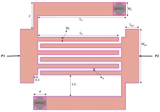
Figure 1.
Proposed unit cell P-CRLH phase shifter with Magneto-static field Responsive Structures (MRSs). All dimensions are in mm (). The overall size is at the design frequency of 5.5 GHz.
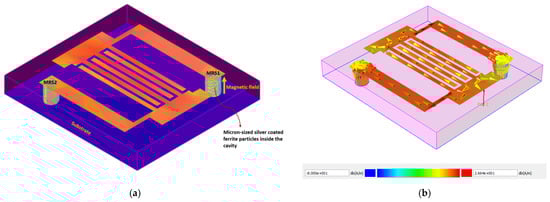
Figure 2.
Isometric view of the proposed unit cell P-CRLH phase shifter with (a) magnetic alignment of particles in Magneto-static field Responsive Structures (MRSs); (b) Surface current distribution at 5.5 GHz when particles inside the MRS are activated.
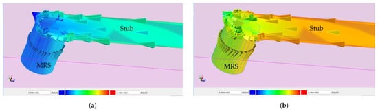
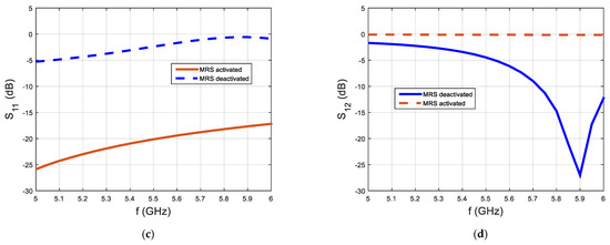
Figure 3.
Illustration of connection/disconnection of a stub with the ground plane using magnetic particle activation/deactivation inside the MRS cavity. (a,c) Surface current distribution and S parameters for a disconnected stub with the ground plane, (b,d) Surface current distribution and S parameters for a connected stub with the ground plane.
2.1. Phase Response of Single- and Cascaded Unit Cells P-CRLH Phase Shifter −45° Phase Shift
The unit cell P-CRLH phase shifter with dimensions in Figure 1 is simulated using the ADS 2016 Momentum simulator with the following EM setup: 50-ohm single-mode ports and with TML calibration, mesh frequency is 6 GHz with a mesh density of 20 cells/wavelength. The substrate material used is Rogers RT/duroid 5880LZ ( 2.2, = 0.002 and thickness = 1.27 mm). To mimic, the magnetic alignment of silver-coated ferrite particles in the MRS structure for P-CRLH phase shifter simulation, grounded vias with circular layouts were inserted at the MRS locations. The activation of vias connects the symmetrical stubs with the ground plane, representing the magnetic alignment of particles in the MRS, and the deactivation of vias disconnects the stubs from the ground plane, which represents the non-alignment of particles in the MRSs. The simulated S parameters for single-unit cells and cascaded-unit cells in the ADS Momentum layout are shown in Figure 4. The impedance matching characteristics at the ports () are below −10 dB. The insertion loss is 0.087 dB at 5 GHz and goes up to 0.164 dB at 6 GHz. Therefore, it is concluded that the P-CRLH phase shifter supports the propagation of the electromagnetic wave in the frequency band of interest.
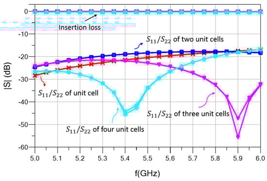
Figure 4.
Simulated S parameter results of the proposed unit cell and cascaded unit cells P-CRLH phase shifter with MRSs embedded on the symmetrical stubs using unit cell phase shift.
The simulated phase responses for the unit cell and cascaded unit cells P-CRLH phase shifter are shown in Figure 5. At the design frequency of 5.5 GHz, the phase shift from port to for a single-unit cell is . For cascaded unit cells, the total phase shift simply adds as demonstrated in [33]. Therefore, for cascaded two-unit cells, the calculated phase shift is , for cascaded three-unit cells, the calculated phase shift is 3 and the calculated phase shift for cascaded four-unit cells is 4. The simulated phase shifts in Figure 5 for cascaded two-, three- and four-unit cells are , and , respectively. The range of phase error is . The effects of the phase error on phased array antenna will be discussed in Section 3.
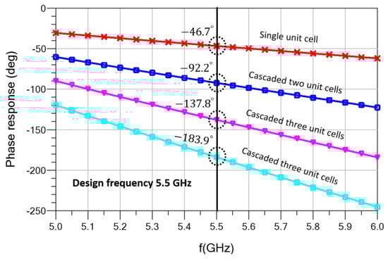
Figure 5.
Simulated phase response results of the proposed unit cell and cascaded unit cells P-CRLH phase shifter with MRSs embedded on the symmetrical stubs for phase shift.
2.2. Phase Response of Single- and Cascaded Unit Cells P-CRLH Phase Shifter −90° Phase Shift
To achieve a phase shift, the unit cell P-CRLH phase shifter in Figure 1 with mm (all other dimensions remain the same) is simulated in the ADS 2016 Momentum environment. The same electromagnetic (EM) setup parameters are used as for the − case in Section 2.1. The simulated S parameters and phase response results are shown in Figure 6 and Figure 7, respectively. The results in Figure 6 show good impedance matching characteristics and insertion loss indicating the propagation of the electromagnetic wave from port 1 to port 2. The calculated phase shift values for unit and cascaded P-CRLH phase shifters at the design frequency of 5.5 GHz are , , and , respectively. The corresponding values of the simulated phase shifts achieved are , , and , respectively, as shown in Figure 7. The range of phase error between the calculated and simulated phase shifts is . The effects of the phase error on the phased array antenna will be discussed in Section 3.
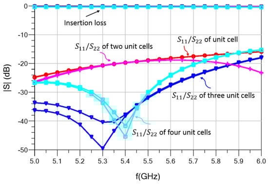
Figure 6.
Simulated S parameter results of the proposed unit cell and cascaded unit cells P-CRLH phase shifter with MRSs embedded on the symmetrical stubs using unit cell phase shift.
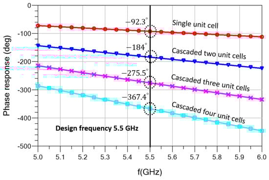
Figure 7.
Simulated phase response results of the proposed unit cell and cascaded unit cells P-CRLH phase shifter with MRSs embedded on the symmetrical stubs for phase shift.
3. Simulated Phased Array with P-CRLH Phase Shifters
A four-element linear patch antenna array operating at the design frequency of 5.5 GHz is simulated in ADS 2016 Momentum. The inter-element center-to-center spacing is with the substrate having a thickness of 1.27 mm, 2.2 and = 0.002. The schematic of the 1 × 4 array with directly excited and integrated P-CRLH phase shifters is shown in Figure 8. The mutual coupling between the adjacent antenna elements for directly excited and P-CRLH-excited phase shifters are shown in Figure 9. The maximum mutual coupling is 13.5 dB at the design frequency for both the direct- and P-CRLH-excited array. From (5.8–6) GHz, the mutual coupling for the directly excited array is significantly less than the P-CRLH-excited array. A ladder resonator [34] can be used to reduce the mutual coupling effects in the patch antenna array structure at the resonant frequency. Next, the P-CRLH phase shifters designed in Section 2.1 and Section 2.2 will be integrated with the array to test their performance for main beam scanning applications.
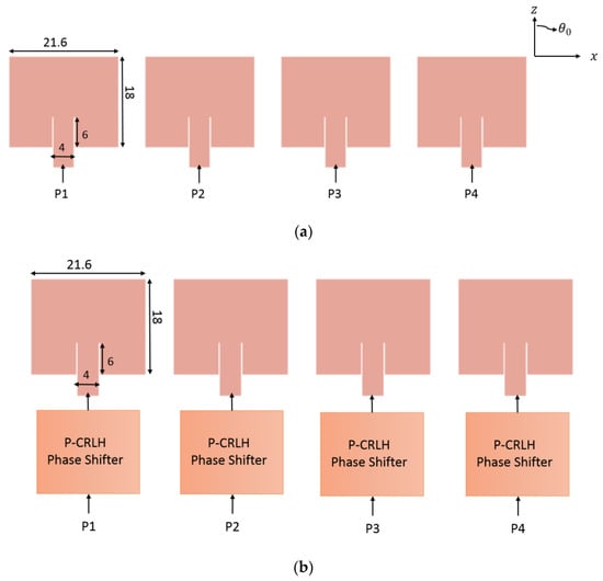
Figure 8.
A 1 × 4 linear phased array with: (a) directly excited phases and (b) P-CRLH-excited phases.
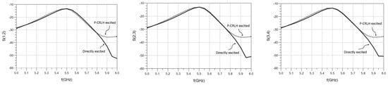
Figure 9.
Simulated mutual coupling between adjacent antenna elements with P-CRLH-excited and without P-CRLH-excited (directly excited) phase shifters.
3.1. Main Beam at Broadside
For the main beam at the broadside, the four patch antenna elements in Figure 8 are individually excited with the unit cell P-CRLH phase shifters in Section 2.1. This will make the feeding of antenna elements with the same phases () at the design frequency of 5.5 GHz and will result in a constructive radiation pattern at the broadside direction. For comparison, the patch antenna elements in the array are directly excited with phases equal to . The simulated far-field radiation patterns with directly excited and P-CRLH-excited phases are shown in Figure 10. Overall, there is a good agreement between the two results with a 0.7 dB difference in the broadside gain and a 1.1 dB difference in the first sidelobe level.
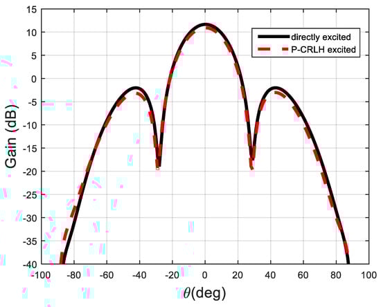
Figure 10.
Simulated main beam at broadside with directly excited and P-CRLH-excited phases.
3.2. Main Beam at 15° Off-Broadside
To scan the main beam at off-broadside of the array axis, the inter-element adjacent phase difference is calculated using the following expression [7]:
where is the direction of main beam from the -axis, is the center spacing between the antenna elements in Figure 8 and is a wave number. For , . This phase shift is achieved using the unit cell P-CRLH phase shifter discussed in Section 2.1. The four patch antenna elements in the array of Figure 8 are excited with unit cell and cascaded unit cells P-CRLH phase shifters having phases of , , and , respectively (see Figure 5). The P-CRLH-excited far-field radiation at 5.5 GHz is shown in Figure 11. Then, for comparison, using Equation (3), the patch antenna elements in the array are directly excited with , , and , and the far-field pattern for the directly excited array is also shown in Figure 11. For both excitation phases, the value of peak gain is 11.5 dB at a scan angle and there is a difference of 0.85 dB for the first sidelobe level values.
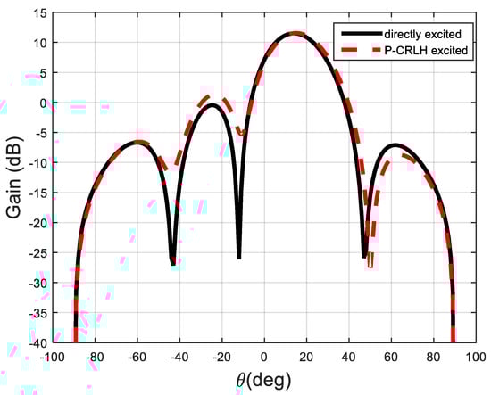
Figure 11.
Simulated main beam at off-broadside with directly excited and P-CRLH-excited phases.
3.3. Main Beam at 30° Off-Broadside
Using Equation (3), for main beam location at . This adjacent element phase shift of is achieved with the P-CRLH phase shifter in Section 2.2. Now, the four patch antenna elements in the array are fed with unit cell and cascaded unit cell P-CRLH phase shifters having excitation phases of −, −, − and − (see Figure 7). The far-field radiation pattern at 5.5 GHz is shown in Figure 12. Again, for comparison, the array elements are directly excited with computed phases () using Equation (3), and the directly excited radiation pattern is also shown in Figure 12. For both the directly and P-CRLH-excited radiation patterns, the location of the main beam is at with a peak gain of 11.5 dB. The difference in the first sidelobe level is 0.77 dB.
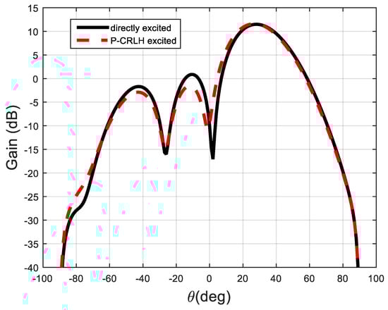
Figure 12.
Simulated main beam at off-broadside with directly excited and P-CRLH-excited phases.
4. Measurements Validation
For measurement validation, three prototypes of a 1 × 4 patch antenna array with integrated P-CRLH phase shifters are manufacured and are shown in Figure 13c. The substrate used has a thickness of 1.27 mm, 2.2 and = 0.002. The dimensions of the patches are shown in Figure 8 (Section 3) operating at 5.5 GHz. The fabricated proposed unit cell P-CRLH phase shifter with dimensions discussed in Section 2 is given in Figure 13b. For size comparison, a photograph of the recently published P-CRLH phase shifter [29] is also shown in Figure 13a. The reflection coefficient, insertion loss and phase response of the fabricated unit cell P-CRLH phase shifter are measured with the Agilent Network Analyzer in Figure 13d. The tiny magnets beneath the ground plane are used to activate the MRSs. The measured results are shown in Figure 14. In Figure 14a, the reflection coefficient is less than 10 dB for both the ports, indicating good impedance matching characteristics, the maximum insertion loss measured is −2 dB, showing good propagation behavior. In Figure 14b, the phase response at design frequency of 5.5 GHz is around , which is in close agreement with the simulated phase of in Figure 7. There are three main advantages of the proposed P-CRLH phase shifter and the proposed P-CRLH phase shifters-excited phased array as compared to similar work in [29]. (1) There is a 60% size reduction in the proposed P-CRLH phase shifter. (2) There is a 73.68% reduction on the requirements of the printed microstrip transmission lines on both ends of the proposed P-CRLH phase shifter. (3) The proposed P-CRLH excited phased array in Figure 13c is fabricated on a single PCB as compared to phased array in [29], where the antenna array and phase shifters are on separate PCBs.
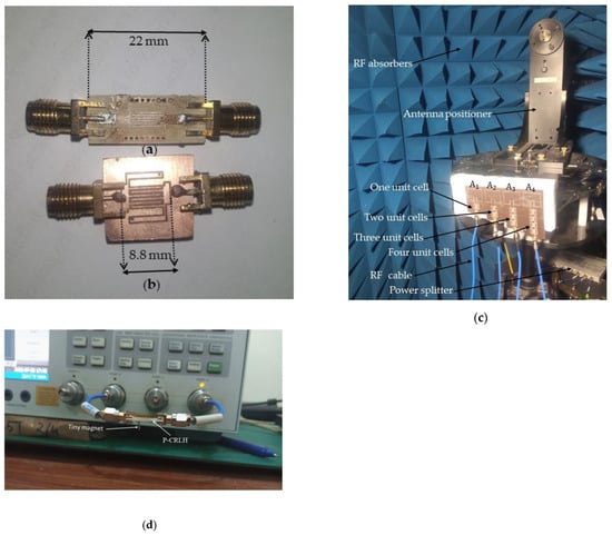
Figure 13.
Photographs of the fabricated (a) unit cell P-CRLH phase shifter reported in [29]; (b) proposed unit cell P-CRLH phase shifter; (c) a 1 × 4 linear phased array with integrated proposed P-CRLH phase shifters in an anechoic chamber and (d) unit cell P-CRLH phase shifter measurements.
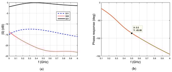
Figure 14.
Measured results of a unit cell P-CRLH phase shifter. (a) Reflection coefficients, insertion loss. (b) Phase response.
Next, the measured results for three prototypes of the broadside scan, the 15-degree scan and the 30-degree scan phased array are discussed.
4.1. Measured Broadside Radiation Pattern
To obtain the broadside radiation pattern, the individual patch antenna elements ( in Figure 13c) in the 1 × 4 phased array must be excited with the same phases. Therefore, the four patches in Figure 13 are equally excited with the unit cell P-CRLH phase shifters in Figure 13b. This will then result in the constructive addition of individual antenna patterns making an overall array pattern with a higher main lobe toward the broadside as shown in the measured results of Figure 15. The measured broadside gain is 10.1 dB and the measured first sidelobe level is 9.1 dB.
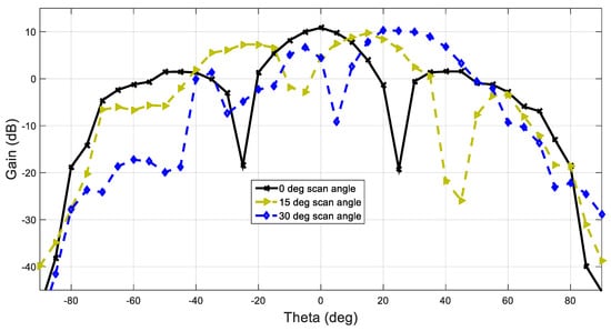
Figure 15.
Measured pattern results of a 1 × 4 phased array with P-CRLH excited phases.
4.2. Measured 15° Off-Broadside Radiation Pattern
To achieve the off-broadside radiation pattern, the antenna element is excited with the unit cell P-CRLH phase shifter discussed in Section 2.1, the antenna element is excited with two-unit cells P-CRLH phase shifters, the antenna element is excited with three-unit cells P-CRLH phase shifters, and the antenna element is excited with four-unit cells P-CRLH phase shifters. This will cause the four antenna elements in the array to be excited with phases , , and , respectively. The 1 × 4 patch array excited with the unit cell and cascaded unit cells P-CRLH phase shifters using a fully calibrated in-house anechoic chamber is shown in Figure 13c. The measured radiation pattern for off-broadside is shown in Figure 15. The measured gain at the scan angle is 10 dB, and the minimum sidelobe level is 12 dB.
4.3. Measured 30° Off-Broadside Radiation Pattern
For the off-broadside radiation pattern, the four patches in Figure 13c are excited with the unit cell and cascaded unit cells P-CRLH phase shifters discussed in Section 2.2. This will ensure phase excitations of the patch elements , and with the phases of , , and , respectively. The resulting measured radiation pattern for the scan angle is shown in Figure 15. The measured peak gain at the scan angle is 9.9 dB, and the value of the minimum sidelobe level is 10 dB.
The comparison data for peak gain and sidelobe level for the three prototypes discussed are given in Table 4. The differences between simulated and measured results are due to non-ideal fabrications, unavailability of exact phases with P-CRLH prototypes and a lack of perfect symmetry in the anechoic chamber.
Table 4.
Comparison between simulated and measured results of a 1 × 4 phased array with P-CRLH excited phases.
5. Discussion and Conclusions
In this work, a novel phase shifter based on a printed composite right/left-handed structure (CRLH) with embedded micron-sized magnetic particles is proposed. Then, a 1 × 4 patch antenna array operating at 5.5 GHz Wi-Fi 6 band is printed, and the patches are integrated with cascaded novel particles embedded CRLH phase shifters for the broadside and phased array applications. The proposed CRLH phase shifter is compact in size (60% size reduction) as compared to the recently published CRLH-based phase shifter. As compared to commercially available phase shifters, the proposed phase shifter does not require electronic components (resistor, inductor and capacitor) for biasing. The commercially available phase shifters require dc biasing circuitry for phase tuning, which can be coupled with the RF signal and may cause phase deviation. The proposed phase shifter does not require direct biasing arrangements. It operates on the application of a magnetic field to be applied beneath the ground plane and, therefore, isolates the coupling of the RF signal with the biasing circuitry. The proposed phase shifter can be directly integrated with the phased array in a fully planar requirement. In this study, the novel particles-CRLH phase shifters are experimentally tested with a 1 × 4 patch phased array for , and main beam scanning. The measured results are shown in good agreement with the simulated patterns. A possible future extension of the work is to extend the design of the proposed phase shifter for fully printing conformal array applications on a commercial router system for Wi-Fi 6.
Author Contributions
M.A. performed complete simulations, fabrications and measurements. I.U. supervised the research work and assisted in measurements, overall paper management, idea development and manuscript writing. All authors have read and agreed to the published version of the manuscript.
Funding
This work is jointly supported by Ignite (National Technology Fund via Project No. ICTRDF/TR&D/2015/04) and NRPU-HEC (via Project No. 20-14696/NRPU/R&D/HEC/2021), Pakistan. The APC was paid by Wesam Khalil, Server Security Integration Group, Intel Corporation, 2111 NE 25th Ave, Hillsboro, OR 97124, USA. Wesam Khalil assisted in simulations and provided access to software and hardware resources.
Data Availability Statement
All data have been included in study.
Conflicts of Interest
The authors declare no conflict of interest.
References
- Mozaffariahrar, E.; Theoleyre, F.; Menth, M. A survey of Wi-Fi 6: Technologies, Advances, and Challenges. Future Internet 2022, 14, 293. [Google Scholar] [CrossRef]
- D-Link. Available online: https://eu.dlink.com/rs/sr/-/media/resource-centre/brochures-and-product-guides/dlink-wifi-6-whitepaper.pdf (accessed on 28 January 2023).
- CISCO. Available online: https://www.cisco.com/c/en/us/products/collateral/wireless/white-paper-c11-740788.html (accessed on 28 January 2023).
- Huawei Enterprise. Available online: https://e.huawei.com/au/material/networking/wlan/f3ae84efd98d440eb457b4caf405b509 (accessed on 28 January 2023).
- ZTE. Available online: https://res-www.zte.com.cn/mediares/zte/Files/PDF/white_book/Wi-Fi_6_Technology_and_Evolution_White_Paper-20200923.pdf?la=en (accessed on 28 January 2023).
- Quectel. Available online: https://www.quectel.com/wp-content/uploads/2022/02/WiFi-6-WP-21.02.22.pdf (accessed on 28 January 2023).
- Hansen, R.C. Phased Array Antennas, 2nd ed.; John Wiley and Sons, Inc: New York, NY, USA, 2009; p. 580. [Google Scholar]
- Iftikhar, A.; Parrow, J.; Asif, S.; Allen, J.; Allen, M.; Braaten, B.D. Improving the efficiency of a reconfigurable microstrip patch using magneto-static field responsive structures. Electron. Lett. 2016, 52, 1194–1196. [Google Scholar] [CrossRef]
- Yasir, M.; Fatikow, S.; Haenssler, O.C. Amplitude-phase variation in a graphene-based microstrip line. Micromachines 2022, 13, 1039. [Google Scholar] [CrossRef] [PubMed]
- Jin, R.; Cai, Z.; Dong, M.; Luo, Y.; Yang, Y.; Qi, Y. Compact conformal wideband antenna for high-speed WLAN applications. Int. J. RF Microw. Comput. Aided Eng. 2020, 30, e22293. [Google Scholar] [CrossRef]
- Hu, Z.; Xiao, Z.; Jiang, S.; Song, R.; He, D. A Dual-Band Conformal Antenna Based on Highly Conductive Graphene-Assembled Films for 5G WLAN Applications. Materials 2021, 14, 5087. [Google Scholar] [CrossRef] [PubMed]
- Nikfalazar, M.; Sazegar, M.; Zheng, Y.; Wiens, A.; Jakoby, R.; Friederich, A.; Kohler, C.; Binder, J.R. Compact tunable phase shifter based on inkjet printed BST thick-films for phased-array application. In Proceedings of the 2013 European Microwave Conference, Nuremberg, Germany, 6–10 October 2013. [Google Scholar]
- Nikfalazar, M.; Sazegar, M.; Friederich, A.; Kohler, C.; Zheng, Y.; Wiens, A.; Binder, J.R.; Jakoby, R. Inkjet printed BST thick-films for X-band phase shifter and phased array applications. In Proceedings of the 2013 International Workshop on Antenna Technology (iWAT), Karlsruhe, Germany, 4–6 March 2013. [Google Scholar]
- Nikfalazar, M.; Sazegar, M.; Mehmood, A.; Wiens, A.; Friederich, A.; Maune, H.; Binder, J.R.; Jakoby, R. Two-dimensional beam-steering phased-array antenna with compact tunable phase shifter based on BST thick films. IEEE Antennas Wirel. Propag. Lett. 2016, 16, 585–588. [Google Scholar] [CrossRef]
- Sazegar, M.; Zheng, Y.; Maune, H.; Zhou, X.; Damm, C.; Jakoby, R. Compact left handed coplanar strip line phase shifter on screen printed BST. In Proceedings of the 2011 IEEE MTT-S International Microwave Symposium, Baltimore, MD, USA, 5–10 June 2011. [Google Scholar]
- Sazegar, M.; Zheng, Y.; Maune, H.; Damm, C.; Zhou, X.; Binder, J.; Jakoby, R. Low-cost phased-array antenna using compact tunable phase shifters based on ferroelectric ceramics. IEEE Trans. Microw. Theory Tech. 2011, 59, 1265–1273. [Google Scholar] [CrossRef]
- Sazegar, M.; Zheng, Y.; Maune, H.; Zhou, X.; Damm, C.; Jakoby, R. Compact artificial line phase shifter on ferroelectric thick-film ceramics. In Proceedings of the 2010 IEEE MTT-S International Microwave Symposium, Anaheim, CA, USA, 23–28 May 2010. [Google Scholar]
- Haghzadeh, M.; Jaradat, H.M.; Armiento, C.; Akyurtlu, A. Design and simulation of fully printable conformal antennas with BST/polymer composite based phase shifters. Prog. Electromagn. Res. C 2016, 62, 167–178. [Google Scholar] [CrossRef]
- Zhang, J.; Zhang, S.; Ying, Z.; Morris, A.S.; Pedersen, G.F. Radiation-pattern reconfigurable phased array with p-i-n diodes controlled for 5G mobile terminals. IEEE Trans. Microw. Theory Tech. 2019, 68, 1103–1117. [Google Scholar] [CrossRef]
- Maassel, M.; Braaten, B.D.; Rogers, D.A. A metamaterial-based multiband phase shifter. In Proceedings of the IEEE International Conference on Electro/Information Technology, Milwaukee, WI, USA, 5–7 June 2014. [Google Scholar]
- Liu, Q.; Wang, N.; Wu, C.; Wei, G.; Smolders, A.B. Frequency reconfigurable antenna controlled by multi-reed switches. IEEE Antennas Wirel. Propag. Lett. 2015, 14, 927–930. [Google Scholar] [CrossRef]
- Hwang, S.H.; Jang, T.; Kim, J.M.; Kim, Y.K.; Lim, S.; Baek, C.W. MEMS-tunable composite right/left-handed (CRLH) transmission line and its application to a phase shifter. J. Micromech. Microeng. 2011, 21, 125022. [Google Scholar] [CrossRef]
- Potters Industries LLC. Available online: http://www.pottersbeads.com/ (accessed on 28 January 2023).
- Parrow, J. Equivalent Circuit Modeling and Signal Integrity Analysis of Magneto-Static Responsive Structures, and Their Applications in Changing the Effective Permittivity of Microstrip Transmission Lines. Ph.D. Thesis, North Dakota State University, Fargo, ND, USA, 2016. [Google Scholar]
- Iftikhar, A.; Parrow, J.M.; Asif, S.M.; Fida, A.; Allen, J.; Allen, M.; Braaten, B.D.; Anagnostou, D.E. Characterization of novel structures consisting of micron-sized conductive particles that respond to static magnetic field lines for 4G/5G (Sub-6 GHz) reconfigurable antennas. Electronics 2020, 9, 903. [Google Scholar] [CrossRef]
- Soufizadeh-Balaneji, N.; Kallmeyer, A.R.; May, S.; Braaten, B.D. A 360-degree rotatable RF switch (360-RS) with embedded conductive micro-particles. In Proceedings of the 2019 IEEE MTT-S International Microwave Symposium (IMS), Boston, MA, USA, 2–7 June 2019. [Google Scholar]
- Iftikhar, A.; Parrow, J.; Asif, S.; Braaten, B.D.; Allen, J.; Allen, M.; Wenner, B. On using magneto-static responsive particles as switching elements to reconfigure microwave filters. In Proceedings of the 2016 IEEE International Conference on Electro Information Technology 315 (EIT), Grand Forks, ND, USA, 19–21 May 2016. [Google Scholar]
- Caloz, C.; Itoh, T. Electromagnetic Metamaterials: Transmission Line Theory and Microwave Applications, 1st ed.; Wiley-IEEE Press: New York, NY, USA; John Wiley and Sons, Ltd.: Hoboken, NJ, USA, 2006; Chapter 3; pp. 122–131. [Google Scholar]
- Ayaz, M.; Iftikhar, A.; Braaten, B.D.; Khalil, W.; Irfanullah. A composite right/left-handed phase shifter based cylindrical phased array with reinforced particles responsive to magneto-static fields. Electronics 2023, 12, 306. [Google Scholar] [CrossRef]
- Zhang, J.; Cheung, S.W.; Yuk, T.I. Design of n-bit digital phase shifter using single CRLH TL unit cell. Electron. Lett. 2010, 46, 506. [Google Scholar] [CrossRef]
- Zhang, J.; Cheung, S.W.; Yuk, T.I. Design of n-bit phase shifters with high power-handling capability inspired by composite right/left-handed transmission line unit cells. IET Microw. Antennas Propag. 2010, 4, 991–999. [Google Scholar] [CrossRef]
- Iftikhar, A.; Asif, S.M.; Parrow, J.M.; Allen, J.W.; Allen, M.S.; Fida, A.; Braaten, B.D. Changing the operation of small geometrically complex EBG-based antennas with micron-sized particles that respond to magneto-static fields. IEEE Access 2020, 8, 78956–78964. [Google Scholar] [CrossRef]
- Antoniades, M.A. Compact Linear Metamaterial Phase Shifters for Broadband Applications. Master’s Thesis, University of Toronto, Toronto, ON, Canada, 2004. [Google Scholar]
- Roshani, S.; Shahveisi, H. Mutual coupling reduction in microstrip patch antenna arrays using simple microstrip resonator. Wirel. Pers. Commun. 2022, 126, 1665–1677. [Google Scholar] [CrossRef]


Disclaimer/Publisher’s Note: The statements, opinions and data contained in all publications are solely those of the individual author(s) and contributor(s) and not of MDPI and/or the editor(s). MDPI and/or the editor(s) disclaim responsibility for any injury to people or property resulting from any ideas, methods, instructions or products referred to in the content. |
© 2023 by the authors. Licensee MDPI, Basel, Switzerland. This article is an open access article distributed under the terms and conditions of the Creative Commons Attribution (CC BY) license (https://creativecommons.org/licenses/by/4.0/).