Featured Application
The presented results can be used in designing synchronous homopolar machines and railway undercar generators.
Abstract
The article presents the optimal design of a 35 kW brushless synchronous homopolar generator without permanent magnets for railway passenger cars. The excitation winding of the generator is located on the stator, and the toothed rotor has no windings. The generator characteristics are optimized considering the required constant power speed range. A single-objective Nelder–Mead algorithm and 2D Finite Element Analysis were used for the optimization. As a result of the optimization, power losses are significantly reduced over the entire operating range of the generator rotational speed, the current capacity of the solid-state rectifier, and the torque ripple. A comparison of the calculated characteristics of the generator under consideration with the characteristics of a commercially available undercar generator shows that the active volume is reduced by a factor of 2.1, and the losses are significantly reduced over the entire operating speed range.
1. Introduction
In many countries, less than half of the railways are electrified [1,2]. Nonelectrified railway lines use diesel or diesel–electric locomotives [3]. One of the options for the electrification of passenger cars in this case is undercar generators [4,5].
Brushless synchronous homopolar machines (SHMs) with axial excitation flux and stator-fixed concentric coils of the excitation winding are known for their high reliability, due to which they find use in flywheel energy storage and traction motors, as well as in welding automotive and aircraft generators [6,7,8,9]. They can be used at high temperatures and in hazardous environments, such as drives [10] and high-power wind generators [11]. The main benefit of SHMs, in comparison with conventional generators with electrically excited rotor, is high reliability, due to the simple rotor without windings, no sliding contact, and reliable concentric excitation winding coils located on the stator. At the same time, the SHM retains the ability to control the excitation current, as in a conventional generator with an excitation winding on the rotor.
It is also a problem to ensure the cooling of a conventional generator with an excitation winding on the rotor, which has significant electrical losses. Generators with a brushless exciter are used in a number of applications, such as aircraft generators and high-power generators [12,13]. The disadvantages of such generators with a brushless exciter, compared with brushed generators, include an increase in the cost, dimensions, and weight of the machine due to the presence of a brushless exciter. Additionally, in this case, there are problems of the reliability and repair of the brushless exciter assembly.
The design of the excitation winding is much simpler and more reliable and requires much less copper that that of a conventional synchronous generator. In addition, because the rotor does not have windings and a significant copper loss associated with them, no special measures are required to cool the rotor [14]. Another important advantage of the SHG is the high strength of the rotor to the centrifugal force and large shock loads [15].
SHMs have a complex configuration of the magnetic system, which is inconvenient for calculation and optimization, because the magnetic flux propagates in all three dimensions. The magnetic flux flows in the axial direction in laminated parts of the machine and in the transverse plane in nonlaminated parts of the machine’s magnetic core. The complex three-dimensional design of the magnetic circuit causes difficulties when using conventional two-dimensional models based on the finite element analysis (FEA) to compute the characteristics of the SHM.
Because analytical models of electrical machines are usually not accurate enough due to the difficulty of taking into account the saturation of the magnetic circuit, it is necessary to use numerical models [16].
For this reason, a number of numerical calculation methods have been proposed for SHMs, taking into account the saturation of the magnetic circuit, including three-dimensional FEA [17,18,19], two-dimensional FEA [9,20], one-dimensional magnetic circuits, and their various combinations [21,22]. In Reference [9], a simplified SHM modeling technique was proposed, in which the features of the SHM magnetic field are taken into account in a two-dimensional model by introducing the excitation field term into the equations of the magnetic vector potential and solving the 2D magnetostatic problems complemented with an equivalent circuit equation for the excitation flux.
Articles [9,23,24,25,26,27] present SHM as a traction motor. Article [9] discusses a simplified methodology for estimating the characteristics of the SHM, suitable for use in multi-iteration automatic optimization, and its experimental verification. Articles [23,24,25] present techniques for optimizing SHMs for various traction applications. Articles [14,26] present the results of comparing the characteristics of the SHM with other types of traction motors. Article [27] presents the development of a control strategy for the traction SHM.
In References [6,17,18,20,28,29,30], the analysis of the SHM characteristics for various generator applications is investigated. In Reference [17], the modeling and tuning of the control system of a high-speed synchronous homopolar generator (SHG) is considered. In [18], the analytical formulas for the design and the results of 3D FEA of a high-grade SHG with a power of 10 kW and a rotation speed of 24 krpm are described. In Reference [20], the simulation of a low-power SHG with a speed of 3000 rpm at idle is considered using a 2D FEA with virtual excitation windings. In Reference [28], a theoretical evaluation of the characteristics of an SHG with a power of 500 kW with a superconducting excitation winding is presented. In Reference [30], the manual optimization of SHG performance at no-load is considered, and an experimental verification is carried out.
In References [6,29], the analysis of SHG characteristics for undercar generators is considered. In Reference [6], the modeling of a 4.5 kW undercar generator is considered, taking into account the eccentric installation of the rotor. In Reference [29], the modeling of the design of an undercarriage generator based on SHG with hybrid excitation is considered.
Based on the literature overview, it can be concluded that previous studies are limited to the manual optimization of the SHG no-load characteristics, as in [30], but do not carry out computer-aided optimization ((CAO), for example, using a genetic algorithm or the Nelder–Mead method) of the SHG on-load performance using FEA due to the fact that the 3D FEA of SHM takes too much time. At the same time, improving the performance of undercar SHGs through optimization is important to reduce their volume (and therefore cost) and power losses, which is required in practice [15].
The novelty of this article is to demonstrate that the proposed technique of CAO of the SHG on-load characteristics, based on the simplified model [9] and the Nelder–Mead method, makes it possible to reduce the volume (cost) and the power loss compared to a commercially available counterpart [31]. To overcome difficulties with the long 3D FEA time, it is proposed to use the simplified 2D SHM model presented in [9].
The optimization procedure was developed, which takes into account the operating cycle of the generator. The objectives of the optimization are to minimize losses in the generator, minimize the maximum current of the controlled rectifier, and minimize torque ripple.
The optimization procedure requires the calculation of only two operating points of the generator, which ensures a short calculation time. The target characteristics of the SHG as a result of optimization are significantly improved. The article also compares the main characteristics of an optimized SHG with a mass-produced undercar generator.
2. General Description of the SHG Design
An SHG consists of two or more SRCSs connected to each other in the axial direction by ferromagnetic structural elements. The excitation current is provided by the excitation winding located on the stator. The magnetic flux of the excitation winding is closed through the SRCSs by means of the stator housing and the sleeve on the rotor shaft [30,32]. This magnetic flux is modulated by the rotor teeth, which allows it to interact with the poles of the stator winding. In this case, half of the poles are involved. The addition of ferrite magnets to the SHG makes it possible to use all poles of the stator winding
Figure 1 shows the considered SHG design. The SHG has two stacks on the stator and two stacks on the rotor made of laminated steel. Each stack of rotor and stator is located in front of each other and forms the stator–rotor stack combination (SRSC). The stator lamination has 54 slots and 12-pole winding with a number of slots per pole and phase q = 54/(12∙3) = 1.5.
An excitation winding is located between the SRSCs and is attached to the nonmagnetic supporting core. The nonmagnetic supporting core has slots of the same shape as the laminated stator cores through which the armature winding coils pass. Figure 1b shows the configuration of one armature winding coil. The pitch of the armature coils is four slots. Such a distributed winding is conventional for an SHG design and is widely used in practice.
The rotor is salient-pole and has no windings. Each rotor stack has six teeth, and the teeth of the rotor stacks are shifted by 30 mechanical degrees. The SHG housing and the rotor sleeve carry the stator lamination and the rotor lamination, respectively. They are made of a solid (not laminated) steel and provide the link to the flux produced by excitation winding.
It is assumed that the generator delivers power to the DC link through a controlled rectifier with transistor switches, as shown in the diagram in Figure 2. The required DC voltage (corresponding to the amplitude line voltage of the electric machine) should not exceed 116 V. At preliminary calculations, it was found that without parallel branches, each layer of the power winding should contain only one turn. This leads to large eddy losses. Therefore, the number of parallel branches is chosen equal to the number of pole pairs six.
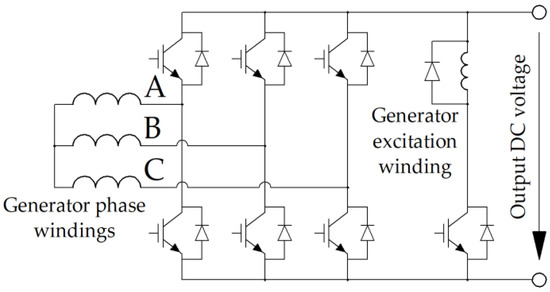
Figure 2.
Schematics of the three-phase-controlled rectifier with a DC chopper to supply the excitation winding. The uppercase letters indicate the phases A, B, C of the generator.

Figure 1.
Sketch of the SHG geometry: (a) Stator cross-section and winding pattern (1/4 of the machine is shown). The uppercase letters indicate the location and direction of the sides of the coils of phases A, B, C in the slots. (b) General view. Only one coil of the armature winding is shown. The rest of the coils are not shown. The two-layer armature winding has 54 coils in total.

3. Operating Points of the Generator, Variable Geometric Parameters, and Objective Function
In the traction drive, motors with a wide speed range at a constant mechanical power (CPSR) are common [25]. An unavoidable feature of CPSR is an increased load on the mechanical part (torque) at low speeds. As a natural generalization for a generator, there could be a requirement for a given range of speeds with a constant output power (active power minus the power of the excitation winding). However, at low speeds and high torques, machine saturation and losses increase, and efficiency also decreases. Therefore, even more mechanical power and even more torque are required. Therefore, in this paper, the generator with a given CPSR is considered.
The rotational speed of the undercar generator increases as the speed of the train increases. The undercar generator described in [31] provides a constant power of 35 kW in the speed range from 750 rpm to 3450 rpm. This paper describes the generator with a CPSR from n2 = 750 rpm to n1 = 3450 rpm and the rated mechanical power of Pmax = 40 kW (Figure 3). It is expected that the averaged value of the output power estimates as the average losses in the modes with the speeds of 750 rpm and 3450 rpm is close to 35 kW. Mechanical losses, namely bearing and windage losses, were neglected.
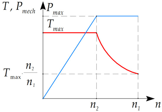
Figure 3.
The dependences of the mechanical power Pmech (blue line) and torque T (red line) on the generator shaft on the rotation speed n.
During the optimization, it is necessary to minimize the following characteristics of the generator (the most important characteristics are listed first):
- Average losses <Ploss>, which were estimated as the average losses in the modes with the speeds of 750 rpm and 3450 rpm;
- Maximum value of the stator current Iarm (reached at 750 rpm mode);
- Maximum symmetrized torque ripple max(TRsym) in both modes;
- Maximum nonsymmetrized torque max(TR) in both modes.
When optimizing, both the torque ripple TR of a separate SRSC and the torque ripple TRsym resulting from the addition of the torque waveforms of all SRSCs of the SHG were considered [9].
The material for the housing and the sleeve is solid steel 1010. Because the magnetic properties of structural steel are not reported and are not guaranteed by the manufacturer, in order to guarantee that the drop of the magnetomotive force on the axial magnetic cores will be small compared to the drop on the SRSC, in the course of optimization, the flux density in the stator housing and in the rotor sleeve was limited to 1.6 T.
In this study, the single-criteria unconditional Nelder–Mead method was used to optimize the SHG design. Therefore, the objective function was given as a product of individual characteristics raised to a certain power, reflecting the importance of the characteristic. Optimization constraints cannot be set by assigning an infinite value to the optimization function if these conditions are not met, as this would lead to a rapid decrease in the volume of the simplex and convergence to an undesirable local minimum. Therefore, the maximum flux density constraint was set as a soft constraint; that is, the corresponding multiplier begins to increase rapidly if the constraint is not complied. In view of the above, the objective function is defined as follows:
where <Ploss> are the average losses (the arithmetic average of total losses at operating points at 750 and 3450 rpm); max(Iarm) and Bh are the values of current and magnetic flux density in nonlaminated steel in the 750 rpm operation point (the maximum values); max(TRsym) is the maximum value of the symmetrized torque ripple; max(TR) is the maximum value of the nonsymmetrized torque ripple.
To obtain a more general result, optimization was carried out under the assumption that the number of turns in the armature winding layer Nsec is a real number and may take noninteger values. In addition, the height and width of the winding wire can be arbitrary real numbers, without taking into account the limitations of the standard assortment [33]. The number of turns was selected so that the amplitude value of the line voltage in the 3450 rpm 40 kW mode V3450 (the maximum voltage mode) was equal to 116 V [14]. The number of parallel branches of the armature winding was 6. Figure 4 shows the geometric parameters of the SHG.
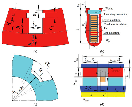
Figure 4.
SHG geometric parameters. (a) Stator slot; (b) Stator winding; (c) Rotor core; and (d) Other dimensions.
Table 1 shows some of the key SHG parameters that were not changed during optimization. Table 2 shows the SHG parameters that were varied during optimization. It was assumed that the shaft does not conduct any flux. The cross sections of the stator housing and the rotor sleeve conducting the same axial excitation flux were taken as equal; therefore, a change in the thickness of the stator housing also causes a change in the outer diameter of the rotor sleeve. When the thickness of the stator housing changes, the outer diameter of the stator lamination also changes.
The width and height of the rectangular armature winding wire wx and wy, necessary to determine the DC and AC (eddy current) losses in the armature winding, were determined based on the dependencies:
where ax = 1.51 mm, ay = 1.8 mm, and Δw = 0.31 mm were determined by the thicknesses of the conductor insulation and slot insulation.
bp = wx + ax; hp = 2∙(wy + Δw) ∙ Nsec + ay,
The net copper fill factor of the excitation winding area was used to calculate the losses in this winding and was assumed to be 0.8. Only DC losses in the excitation winding were taken into account. As Table 2 shows, when optimizing, the electrical angle between the middle of the rotor tooth and the stator current vector (“current angle”) at a speed of 3450 rpm varies. The current angle at 750 rpm was assumed to be 0.1 el. rad.
To reduce the number of parameters changed during optimization, the ratio between the excitation winding current and the current in the armature winding layer was taken as constant. The ratio α2/α1 between the geometrical angular parameters of the rotor slot indicated in Table 2 was also taken as unchanged. Because the housing and the rotor sleeve carry out the same flux, the areas of their cross-sections were assumed to be equal.

Table 1.
Some of the SHG parameters that do not change during optimization.
Table 1.
Some of the SHG parameters that do not change during optimization.
| Parameter | Value |
|---|---|
| Machine length without end winding parts L, mm | 180 |
| Stator housing outer diameter, mm | 370 |
| Axial clearance between excitation winding and rotor, Δa, mm | 15 |
| Radial clearance between field winding and rotor Δr, mm | 12 |
| Shaft diameter, mm | 40 |
| Stator lamination yoke Hstator yoke, mm | 12 |
| Rotor lamination yoke Hrotor yoke, mm | 9 |
| Stator wedge thickness, ε2, mm | 1 |
| Stator unfilled area thickness, ε1, mm | 1 |
| Angle of field weakening at 750 rpm, el. degrees | 0.1 |
| Laminated steel grade | 2412 |
| Laminated steel thickness, mm | 0.35 |
Table 2.
Variable SHG optimization parameters.
Table 2.
Variable SHG optimization parameters.
| Parameter | Initial Design, x0 | Optimized Design, x |
|---|---|---|
| Stator housing thickness h, mm | 15 | 17.1 |
| Total stator stack length Lstator, mm | 150 | 152.7 |
| Stator slot depth, hp, mm | 20 | 29.8 |
| Stator slot width, bp, mm | 5 | 5.6 |
| Airgap width δ, mm | 2 | 0.88 |
| Rotor slot thickness, α1 | 0.5 ∙ tz * | 0.554 ∙ tz * |
| Rotor slot thickness, α2 | 0.6 | 0.665 |
| Angle of field weakening at 3450 rpm, electrical radian | 0.6 | 1.13 |
| Current ratio ** | 8 | 6.43 |
Notes: * The rotor tooth pitch tz = 360°/6 = 60 mechanical degrees; ** the current ratio is the ratio of the current in the armature winding layer to the current in the excitation winding.
Figure 5 shows a flowchart of the calculation of the output of the objective function defined by Equation (1). To find the optimized value of the vector of variable parameters x, the fminsearch(F, x0) MATLAB R2021a procedure was launched, where F is the objective function, according to Figure 5; x0 is the initial vector of variable optimization parameters (see Table 2). The details of the optimization function ‘fminsearch’, which implements the simplex gradientless Nelder–Mead method [34], are well known and described in the documentation of the MATLAB software [35].
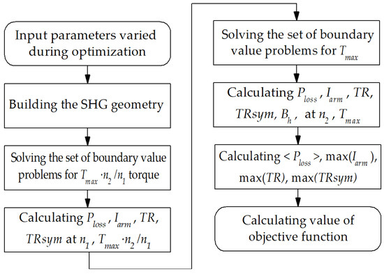
Figure 5.
Objective function flowchart. The input parameters varied during optimization is shown in Table 2. The objective function is defined by Equation (1).
4. Optimization Results
The application of the Nelder–Mead method leads to the convergence of the objective function defined by Equation (1) to a certain minimum (Figure 6). In the course of optimization, the SHG average loss (Figure 7a) and the armature current amplitude (Figure 7b) were also reduced significantly. The nonsymmetrized torque ripple, that has the smallest power in the objective function (1), increased during the optimization (Figure 8a). However, the symmetrized torque ripple, which is the resultant one of the SHM as a whole, slightly decreased after the optimization (Figure 8b), which indicates that the torque waveforms of the individual SRSCs are in opposite phase and cancel each other out. Figure 9 and Figure 10 show the geometry and 2D flux density plot of an SRSC before and after optimization.
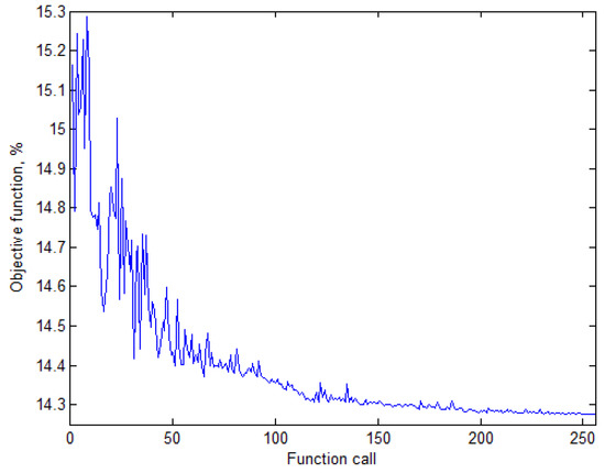
Figure 6.
Change in the value of the objective function defined by Equation (1) in the course of optimization.
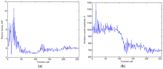
Figure 7.
Change in the SHG performances in the course of optimization. (a) average losses and (b) maximum armature current amplitude.
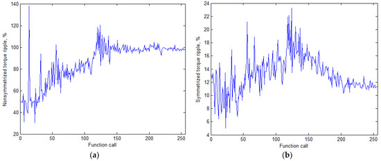
Figure 8.
Change in the SHG parameters in the course of optimization. (a) nonsymmetrized torque ripple and (b) symmetrized torque ripple.
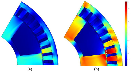
Figure 9.
The cross-section of the SHG initial design and its plot of flux density magnitude (T); areas of extreme saturation (>2T) are colored white: (a) at 3450 rpm and (b) at 750 rpm.
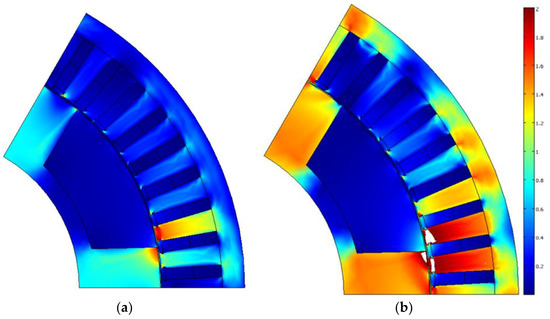
Figure 10.
The cross-section of the SHG optimized design and its plot of flux density magnitude (T); areas of extreme saturation (>2T) are colored white: (a) at 3450 rpm and (b) at 750 rpm.
Comparison of the SHG parameters before and after optimization, shown in Table 3 allows us to draw the following conclusions:
- (1)
- The losses in operating point 2 reduce by 100% (11.56 − 8.10)/11.56 = 30%;
- (2)
- The losses in operating point 1 are much lower than those in point 2, and their increase by 3.84/2.52 = 1.5 times is not so bad. In addition, it is the price for the reduction in the required rectifier power by 100% (100.6 − 67.9)/100.6 = 32.5%, which is achieved by increasing the field weakening angle;
- (3)
- However, average losses reduce by 100% (7.04 − 5.97)/7.04 = 15.2%;
- (4)
- To demonstrate the ability of the SHG to produce energy at a speed lower than 750 rpm, the 300 rpm mode was calculated. To reduce saturation and losses, the torque equal to 90% of the torque in point 2 was chosen. The output power is 8.03 kW; the input power is 14.42 kW, and the generator efficiency is 56%;
- (5)
- After optimization, the maximum symmetrized torque ripple (ripple at the shaft at low speed was reduced by 100% (13.1 − 11.3)/13.1 = 13.7%;
- (6)
- Comparison of the initial and the optimized designs shows that as a result of optimization, the area of the stator slots for the winding increased by increasing the height and reducing the thickness of the stator tooth, which leads to a decrease in the armature winding resistance and the DC losses in the winding.
Table 3.
Optimization results.
Table 3.
Optimization results.
| Parameter | Initial Design | Optimized Design | ||
|---|---|---|---|---|
| Operating point | 1 | 2 | 1 | 2 |
| Rotational speed n, rpm | 3450 | 750 | 3450 | 750 |
| Amplitude of the armature phase current Iarm, A | 388.6 | 1001.7 | 369.5 | 676.2 |
| Efficiency η *, % | 93.7 | 71.1 | 90.4 | 79.8 |
| Input mechanical power Pmech, kW | 40 | 40 | 40 | 40 |
| Active electrical power P1, kW | 37.67 | 29.33 | 36.58 | 33.12 |
| Output electrical power P1 − Pex, kW | 37.5 | 28.4 | 36.2 | 32.0 |
| Armature DC copper loss Parm DC, kW | 1.55 | 10.30 | 1.90 | 6.37 |
| Armature eddy current copper loss Parm AC, W | 123 | 51 | 417 | 131 |
| Stator lamination loss Piron st, W | 663 | 359 | 961 | 403 |
| Rotor lamination loss Piron rt, W | 51 | 10 | 192 | 26 |
| Excitation copper loss Pex, W | 129 | 837 | 368 | 1169 |
| Total loss Ploss **, kW | 2.52 | 11.56 | 3.84 | 8.10 |
| Average loss <Ploss>, kW | 7.04 | 5.97 | ||
| Number of turns in armature winding | 5.14 | 7.75 | ||
| Required rectifier power, kW | 100.6 | 67.9 | ||
| Power factor | 0.969 | 0.668 | 1.000 | 0.747 |
| Line-to-line voltage amplitude Varm, V | 116.0 | 51.3 | 116.0 | 75.3 |
| Nonsymmetrized torque ripple, % | 49.7 | 33.7 | 97.8 | 47.0 |
| Symmetrized torque ripple, % | 13.1 | 5.0 | 11.3 | 4.5 |
| Magnetic flux density in the housing and the sleeve Bh, T | 1.00 | 1.91 | 0.84 | 1.60 |
* Note: the generator efficiency was calculated as η = (P1 − Pex)/Pmech, where P1 is the active power in armature winding; Pex is the loss in the excitation winding; Pmech is the input (mechanical) power. Mechanical losses, namely bearing and windage losses, were neglected; ** the total loss is the sum of all individual loss components Ploss = Parm DC + Parm AC + Piron st + Piron rt + Pex.
The original design has a flux density in nonlaminated parts of more than 1.6 T. Due to the introduction of an appropriate multiplier in the optimization function defined by Equation (1), in the final design, the thickness of the stator housing is increased, and the induction does not exceed 1.6 T.
The rotor sleeve radius is also automatically increased, for the housing and rotor sleeve cross-section areas are equal. The increase in the housing thickness and the stator slot depth leads to a decrease in the airgap radius, which is partially compensated by an increase in the stator stack length. Table 3 compares the SHG characteristics before and after optimization.
5. Performance Comparison of the Optimized Design with a Commercially Available Undercar Generator
This section compares the characteristics of the proposed optimized design of the generator with a serially produced undercarriage generator with an excitation winding on the stator EGV.08.1 with a rated power of 35 kW [31]. Table 4 shows the comparison results of the considered generators.
Table 4.
Performance comparison of the optimized SHG design with a commercially available undercar generator.
The results of comparing the calculated optimized characteristics of the SHG with the characteristics of a commercially produced generator allow us to draw the following conclusions:
- (1)
- The volume of the active part of the optimized SHG is 0.04/0.019 = 2.1 times smaller than that of a mass-produced generator. It is expected that the mass and the cost of the optimized SHG will be less than that of the mass-produced generator;
- (2)
- The calculated efficiency of the optimized SHG neglecting mechanical losses is much greater than the efficiency of the mass-produced SHG over the entire range of operation. The mechanical losses that are mainly small losses in the bearings cannot reduce the efficiency significantly;
- (3)
- The reduced input (mechanical) power due to the reduction of power loss of the SHG results in reducing the load on the transmission elements and wheels of the car, which will increase their lifetime.
6. Conclusions
This article discusses the methodology and results of optimizing a synchronous homopolar generator (SHG) with an output power of approximately 35 kW without permanent magnets for railway passenger cars. Because the rotational speed of the generator changes as the velocity of the train changes, the performance of the generator is optimized for the required speed range. To reduce the saturation and the currents at low speeds, a constant mechanical power speed range (CPSR) strategy widely used for traction motors is proposed for the undercar generator. The CPSR of the SHG is from 750 rpm to 3450 rpm.
The SHG starts to produce electric energy at the speeds much lower than the low boundary of the CPSR, which is a significant advantage when the passenger car starts with the discharged batteries. Thus, it produces 8.03 kW at 300 rpm.
An optimization procedure was adapted to use the single-criteria, unconstrained Nelder–Mead method. The optimization minimizes the SHG average power loss over the CPSR, the current capacity of the semiconductor rectifier, and the torque ripple. The optimization results show a significant improvement of the target performances of the SHG with ferrite magnets. Compared to the nonoptimized design, the following were reduced: average generator losses by 14.6%, required current capacity of the semiconductor rectifier by 24.8%, and torque ripple by 18.2%.
The calculated characteristics of the SHG were compared with the catalogue characteristics of a commercial undercar generator. The comparison shows that the volume of the SHG electromagnetic core is 2.1 times smaller than that of the commercial generator. At the same time, the calculated efficiency of the SHG is much higher than that of the commercial generator in the entire operating speed range.
In addition, the reduced input (mechanical) power due to the reduction of power loss of the SHG results in reducing the load on the transmission elements and wheels of the car, which will increase their lifetime.
Author Contributions
Conceptual approach, V.D. and V.P.; data duration, V.D. and V.K.; software, V.D. and V.P.; calculations and modeling, V.D., V.K. and V.P.; writing—original draft, V.D., V.K. and V.P.; visualization, V.D. and V.K.; review and editing, V.D., V.K. and V.P. All authors have read and agreed to the published version of the manuscript.
Funding
The research funding from the Ministry of Science and Higher Education of the Russian Federation (Ural Federal University Program of Development within the Priority-2030 Program) is gratefully acknowledged.
Institutional Review Board Statement
Not applicable.
Informed Consent Statement
Not applicable.
Data Availability Statement
Data are contained within the article.
Acknowledgments
The authors thank the editors and reviewers for careful reading and constructive comments.
Conflicts of Interest
The authors declare no conflict of interest.
References
- Percentage of the Railway Lines in Use in Europe in 2020 which Were Electrified, by Country. Report. Statista. 2023. Available online: https://www.statista.com/statistics/451522/share-of-the-rail-network-which-is-electrified-in-europe/ (accessed on 29 January 2023).
- Worldwide Rail Electrification Remains at High Volume. Press Release. RailwayPRO Communication Platform. 19 February. 2021. Available online: https://www.railwaypro.com/wp/worldwide-rail-electrification-remains-at-high-volume/ (accessed on 29 January 2023).
- Liudvinavičius, L.; Jastremskas, V. Modernization of diesel-electric locomotive 2M62 and TEP-70 locomotives with respect to electrical subsystem. Procedia Eng. 2017, 187, 272–280. [Google Scholar] [CrossRef]
- Levin, N.; Kamolins, E.; Pugachev, V.; Gusakov, A. Synchronous generator with two-channel excitation for power supply of railway passenger cars. In Proceedings of the 2012 Electric Power Quality and Supply Reliability, Tartu, Estonia, 11–13 June 2012; pp. 1–6. [Google Scholar] [CrossRef]
- Gulbis, K.; Kamolins, E.; Brakanskis, U. Synchronous inductor generator with electrically integrated armature and field windings with improved performance. In Proceedings of the IEEE 8th Workshop on Advances in Information, Electronic and Electrical Engineering (AIEEE), Vilnius, Lithuania, 22–24 April 2021; pp. 1–6. [Google Scholar] [CrossRef]
- Bindu, G.; Basheer, J.; Venugopal, A. Analysis and control of rotor eccentricity in a train-lighting alternator. In Proceedings of the IEEE International Conference on Power, Control, Signals and Instrumentation Engineering (ICPCSI), Chennai, India, 21–22 September 2017; pp. 2021–2025. [Google Scholar] [CrossRef]
- Lorilla, L.; Keim, T.; Lang, J.; Perreault, D. Topologies for future automotive generators: Part I—Modeling and analytics. In Proceedings of the 2005 IEEE Vehicle Power and Propulsion Conference, Chicago, IL, USA, 7 September 2005; pp. 74–85. [Google Scholar] [CrossRef]
- Bianchini, C.; Immovilli, F.; Bellini, A.; Lorenzani, E.; Concari, C.; Scolari, M. Homopolar generators: An overview. In Proceedings of the IEEE Energy Conversion Congress and Exposition, Phoenix, AZ, USA, 17–22 September 2011; pp. 1523–1527. [Google Scholar] [CrossRef]
- Dmitrievskii, V.; Prakht, V.; Anuchin, A.; Kazakbaev, V. Traction Synchronous Homopolar Motor: Simplified Computation Technique and Experimental Validation. IEEE Access 2020, 8, 185112–185120. [Google Scholar] [CrossRef]
- Severson, E.; Nilssen, R.; Undeland, T.; Mohan, N. Dual-purpose no-voltage winding design for the bearingless AC homopolar and consequent pole motors. IEEE Trans. Ind. Appl. 2015, 51, 2884–2895. [Google Scholar] [CrossRef]
- Jeong, J.-S.; An, D.-K.; Hong, J.-P.; Kim, H.-J.; Jo, Y.-S. Design of a 10-MW-Class HTS homopolar generator for wind turbines. IEEE Trans. Appl. Supercond. 2017, 27, 1–4. [Google Scholar] [CrossRef]
- Kutt, F.; Michna, M.; Kostro, G. Non-Salient Brushless Synchronous Generator Main Exciter Design for More Electric Aircraft. Energies 2020, 13, 2696. [Google Scholar] [CrossRef]
- Noeland, J.; Nuzzo, S.; Tessarolo, A.; Alves, E. Excitation System Technologies for Wound-Field Synchronous Machines: Survey of Solutions and Evolving Trends. IEEE Access 2019, 7, 109699–109718. [Google Scholar] [CrossRef]
- Prakht, V.; Dmitrievskii, V.; Kazakbaev, V.; Anuchin, A. Comparative Study of Electrically Excited Conventional and Homopolar Synchronous Motors for the Traction Drive of a Mining Dump Truck Operating in a Wide Speed Range in Field-Weakening Region. Mathematics 2022, 10, 3364. [Google Scholar] [CrossRef]
- Levin, N.; Kamolins, E.; Pugachev, V. Unlike-Pole Inductor Generator with Electrically Integrated Armature and Excitation Windings for the Power Supply Systems of Passenger Cars. Latv. J. Phys. Tech. Sci. 2013, 50, 12–23. [Google Scholar] [CrossRef]
- Ferrari, S.; Pellegrino, G. FEAfix: FEA Refinement of Design Equations for Synchronous Reluctance Machines. IEEE Trans. Ind. Appl. 2020, 56, 256–266. [Google Scholar] [CrossRef]
- Cheshmehbeigi, H.; Afjei, E. Design optimization of a homopolar salient-pole brushless DC machine: Analysis, simulation, and experimental tests. IEEE Trans. Energy Convers. 2013, 28, 289–297. [Google Scholar] [CrossRef]
- Severson, E.; Mohan, N.; Nilssen, R.; Undeland, T. Outer-rotor AC homopolar motors for flywheel energy storage. In Proceedings of the 7th IET International Conference on Power Electronics, Machines and Drives (PEMD), Manchester, UK, 8–10 April 2014; pp. 1–6. [Google Scholar] [CrossRef]
- Hwang, Y.J. Design and Characteristic Analysis of a Homopolar Synchronous Machine Using a NI HTS Field Coil. Energies 2021, 14, 5658. [Google Scholar] [CrossRef]
- Yang, J.; Ye, C.; Liang, X.; Xu, W.; Xiong, F.; Xiang, Y.; Li, W. Investigation of a Two-Dimensional Analytical Model of the Homopolar Inductor Alternator. IEEE Trans. Appl. Supercond. 2018, 28, 5205205. [Google Scholar] [CrossRef]
- Ye, C.; Yang, J.; Xiong, F.; Zhu, Z.Q. Relationship between homopolar inductor machine and wound-field synchronous machine. IEEE Trans. Ind. Electron. 2020, 67, 919–930. [Google Scholar] [CrossRef]
- Belalahy, C.; Rasoanarivo, I.; Sargos, F. Using 3D reluctance network for design a three phase synchronous homopolar machine. In Proceedings of the 34th Annual Conference of IEEE Industrial Electronics, Orlando, FL, USA, 10–13 November 2008; pp. 2067–2072. [Google Scholar] [CrossRef]
- Dmitrievskii, V.; Prakht, V.; Anuchin, A.; Kazakbaev, V. Design Optimization of a Traction Synchronous Homopolar Motor. Mathematics 2021, 9, 1352. [Google Scholar] [CrossRef]
- Prakht, V.; Dmitrievskii, V.; Anuchin, A.; Kazakbaev, V. Inverter Volt-Ampere Capacity Reduction by Optimization of the Traction Synchronous Homopolar Motor. Mathematics 2021, 9, 2859. [Google Scholar] [CrossRef]
- Dmitrievskii, V.; Prakht, V.; Kazakbaev, V.; Anuchin, A. Design Optimization of the Magnet-Free Synchronous Homopolar Motor of a Subway Train. Appl. Sci. 2022, 12, 12647. [Google Scholar] [CrossRef]
- Dmitrievskii, V.; Prakht, V.; Kazakbaev, V.; Anuchin, A. Comparison of Interior Permanent Magnet and Synchronous Homopolar Motors for a Mining Dump Truck Traction Drive Operated in Wide Constant Power Speed Range. Mathematics 2022, 10, 1581. [Google Scholar] [CrossRef]
- Lashkevich, M.; Anuchin, A.; Aliamkin, D.; Briz, F. Control strategy for synchronous homopolar motor in traction applications. In Proceedings of the 43rd Annual Conference of the IEEE Industrial Electronics Society (IECON), Beijing, China, 29 October–1 November 2017; pp. 6607–6611. [Google Scholar] [CrossRef]
- Kalsi, S.; Hamilton, K.; Buckley, R.G.; Badcock, R.A. Superconducting AC Homopolar Machines for High-Speed Applications. Energies 2019, 12, 86. [Google Scholar] [CrossRef]
- Orlova, S.; Pugachov, V.; Levin, N. Hybrid Excitation of the Axial Inductor Machine. Latv. J. Phys. Tech. Sci. 2012, 49, 35–41. [Google Scholar] [CrossRef]
- Janis, D.; Levin, N.; Orlova, S.; Pugachov, V.; Ribickis, L. Optimization of the magnetic circuit of an axial inductor machine based on the calculation and analysis of magnetic field. In Proceedings of the 13th European Conference on Power Electronics and Applications, Barcelona, Spain, 8–10 September 2009; pp. 1–8. Available online: https://ieeexplore.ieee.org/document/5278726 (accessed on 29 January 2023).
- Synchronous Generators Type EGV. The Generators EGV Are Designed for Power Supply of a Passenger Car. Characteristics. Pskov Electric Machine-Building Plant. Available online: https://www.pemz.ru/catalog/dlya_zheleznoy_dorogi/Synchronous_generators_type_EGV/ (accessed on 30 January 2023).
- Guo, S.; Yi, Z.; Liu, P.; Wang, G.; Lai, H.; Yu, K.; Xie, X. Analysis and Performance Evaluation of a Novel Adjustable Speed Drive with a Homopolar-Type Rotor. Mathematics 2022, 10, 3712. [Google Scholar] [CrossRef]
- IEC 60317-0-2:2020; Specifications for Particular Types of Winding Wires—Part 0-2: General Requirements—Enamelled Rectangular Copper Wire. IEC: Geneva, Switzerland, 2020. Available online: https://webstore.iec.ch/publication/63495 (accessed on 30 January 2023).
- Lagarias, J.; Reeds, J.; Wright, M.; Wright, P. Convergence Properties of the Nelder-Mead Simplex Method in Low Dimensions. SIAM J. Optim. 1998, 9, 112–147. [Google Scholar] [CrossRef]
- Find Minimum of Unconstrained Multivariable Function Using Derivative-Free Method. MATLAB Documentation. ©1994–2023 The MathWorks, Inc. Available online: https://www.mathworks.com/help/matlab/ref/fminsearch.html (accessed on 30 January 2023).
- Ponkratov, Y. Electric Machines of Railway Cars; Educational and Methodological Center for Education in Railway Transport: Moscow, Russia, 2016; Available online: https://studref.com/552936/tehnika/konstruktsii_mashin_peremennogo_toka (accessed on 30 January 2023). (In Russian)


Disclaimer/Publisher’s Note: The statements, opinions and data contained in all publications are solely those of the individual author(s) and contributor(s) and not of MDPI and/or the editor(s). MDPI and/or the editor(s) disclaim responsibility for any injury to people or property resulting from any ideas, methods, instructions or products referred to in the content. |
© 2023 by the authors. Licensee MDPI, Basel, Switzerland. This article is an open access article distributed under the terms and conditions of the Creative Commons Attribution (CC BY) license (https://creativecommons.org/licenses/by/4.0/).