Article

Theoretical Investigation of Mesh Relationship and Mesh Stiffness of Internal Spur Gears with Tooth Wear

1
School of Mechanical Engineering, Xi’an Jiaotong University, Xi’an 710049, China
2
State Key Laboratory for Manufacturing Systems Engineering, Xi’an 710061, China
*
Author to whom correspondence should be addressed.
Appl. Sci. 2023, 13(3), 2022; https://doi.org/10.3390/app13032022
Submission received: 24 December 2022 / Revised: 1 February 2023 / Accepted: 1 February 2023 / Published: 3 February 2023
(This article belongs to the Special Issue Signal Analysis and Fault Diagnosis in Mechanical Engineering)

Abstract

:
The internal gear is part of the planetary and epicyclic gear pairs in the transmission system of the helicopter. Gear tooth wear is one of the most usual gear failures. This paper establishes an analytical model to evaluate the influence of tooth wear on the mesh relationship. A new mesh relationship can be derived for internal spur gears with tooth wear by the proposed analytical model. Consequently, using the new mesh relationship, the two most important meshing excitations, mesh stiffness and unloaded static transmission error (USTE), are quantitatively evaluated for the internal gear with tooth wear. The results indicate that tooth wear mainly affects the meshing ranges of single-tooth and double-teeth in mesh stiffness, rather than its amplitude. Additionally, the amplitudes of USTE increase with the increasing wear depth. Finally, this study can offer a foundation for the dynamic modeling and fault diagnosis of internal spur gears with wear faults.

1. Introduction

In gear transmission systems, the internal and external gear pairs are two common meshing forms. Different from the external gear pair that contains two external gears, the internal gear pair includes an external gear and an internal gear. The internal gear pair is usually used in planetary gears, which are widely applied in the gear transmissions of helicopters. The transmission system is a critical life-deciding part of the helicopter, containing dozens of planetary gear pairs. However, when the planetary gear transmission system operates for long-term operation or short-term dry operation, gear wear unavoidably occurs and aggravates the internal gear pairs. As a common form of early failures, tooth wear is a critical factor leading to more serious faults such as the reduction of transmission accuracy and the aggravation of vibration and noise. Helicopter health and usage monitoring systems (HUMS) mainly use the condition indicators to monitor the wear status of the gear components of the transmission system, which needs a clear fault mechanism for the gear wear. Therefore, it is of great significance to accurately evaluate the influence of tooth wear on gear transmission systems. This study intends to establish an analytical model for internal spur gears with tooth wear that can reveal the effects of tooth wear on gear mesh relationship and mesh stiffness and provide instructive information for gear transmission fault diagnosis.
Some studies have in fact focused on the fault mechanism of gear wear. Flodin developed a numerical model based on the Archard’s wear equation to predict mild tooth wear in external and helical gears [1,2]. Bajpai et al. proposed a wear depth prediction methodology of parallel axis gear pairs by combining a FEM-based gear contact model with the Archard’s wear equation [3]. Subsequently, according to the variation of dynamic contact pressures, Ding established a wear evaluation model of gear tooth considering the time-varying wear coefficient [4]. Akbarzadeh predicted the steady state adhesive wear of spur gears under the elastohydrodynamic lubrication (EHL) [5]. Moreover, Osman simulated mild abrasive wear in wide-faced solid spur and helical gears by considering the Archard’s law and the influence of the lubrication regime [6]. Tunalioğlu adapted Archard’s wear equation to investigate wear theoretically [7], and the result was verified experimentally. As can be seen from the aforementioned studies, the Archard’s wear equation has been successfully used for the evaluation of gear tooth wear distribution.
Based on the results of the tooth wear distribution obtained from the above models, some scholars have studied the influences of tooth wear on gear ratio, backlash, tooth profile deviation, mesh stiffness, and transmission error. Akbarzadeh et al. investigated the variation of gear ratio caused by tooth wear [8]. Inspired by the investigation in this work, the mesh relationship of internal spur gears with tooth wear is investigated, which is described in Figure 1. Kuang et al. introduced gear tooth wear into the dynamic model by directly turning the gear tooth wear into the tooth profile deviation [9]. Yuksel et al. employed a computational model to study the effects of tooth wear on the dynamic behavior of planetary gears, in which contact theory and Archard’s wear model were used to obtain the wear distribution [10]. In addition, Wu et al. investigated the increasing backlash caused by gear wear [11]. In their work, the tooth wear was regarded as backlash and then incorporated into the dynamic model. As for the effect of tooth wear on the transmission error, Lundvall proposed a finite element procedure to study the development of transmission error with gear tooth wear [12]. Atanasiu et al. assumed the wear depth as profile error and took the dynamic contact load into account to analyze the transmission error of spur gears [13]. In addition, Chin et al. and Feng et al. used transmission error and vibration signal as the indicators to evaluate gear wear conditions [14,15] but lack a physical explanation from the perspective of dynamics/kinematics. Tooth wear has an important influence on mesh stiffness. Choy et al. qualitatively analyzed the effects of gear wear on the phase and magnitude of gear mesh stiffness [16]. Yesilyurt et al. carried out modal analysis to obtain the reduction of mesh stiffness in spur gears [17]. Liu et al. proposed a wear prediction method which combined loaded tooth contact analysis (LTCA) method and gear dynamic model to evaluate the mesh stiffness of spur gears [18]. Using the same method, Huangfu et al. studied the influences of tooth modification on thin-rimmed gears with tooth wear [19]. Brethee et al. used the variation of contact lines of helical gears to develop an accurate wear detection approach, in which the effects of tooth wear on mesh stiffness was analyzed [20]. A modified analytical mesh stiffness model was derived by Chen et al. [21] who introduced the tooth wear into mesh stiffness. In our previous work, tooth wear was simplified as the change of tooth profile parameters and gear wear only reduces the amplitude of mesh stiffness [22]. The effect of tooth wear on the mesh stiffness was quantitatively analyzed, where tooth wear was equivalent to tooth profile deviation [23]. However, our existing studies mainly focus on the influence of tooth wear on geometric parameters through equivalence or finite element method, while ignore the new mesh relationships caused by tooth wear.
This paper focuses on the evaluation of tooth wear on the gear model, including the mesh relationship, mesh stiffness, and transmission error. Aiming at the shortcomings of existing gear modeling for tooth wear, the main contributions of this paper can be summarized as:
  • An analytical model for a new mesh relationship of internal spur gear with tooth wear is proposed for the first time.
  • The multi-tooth mesh rule to evaluate the effect of tooth wear on the multi-tooth mesh relationship is proposed.
  • According to the new mesh relationship and the multi-tooth mesh rule, the effects of tooth wear on the mesh stiffness and USTE are studied.
The proposed model will reveal the internal gear wear fault mechanism, which is helpful to build the condition indicators and realize the effective monitoring of the wear status of the helicopter transmission system.
The rest of this paper is arranged as follows. In Section 2, the analytical model is introduced and a new mesh relationship of internal spur gears with tooth wear is derived. In Section 3 and Section 4, the multi-tooth mesh rule is explored and the effect of tooth wear on the mesh stiffness and USTE is evaluated. Finally, conclusions are drawn in Section 5.

2. Mesh Relationship Modeling of Internal Spur Gears with Tooth Wear

Generally speaking, we can use mesh relationship to describe the gear relative kinematic relationship when the gears are meshing. In this section, an analytical model is proposed to evaluate the new mesh relationship of internal spur gears caused by tooth wear. Firstly, the single-tooth analytical model of the internal spur gears is established. Subsequently, we establish the single-tooth meshing analytical model with tooth wear through two analytical models. Finally, solving the geometric equations, the new mesh relationship can be derived. Moreover, the results of the new mesh relationship are discussed in the typical case of non-uniform wear.

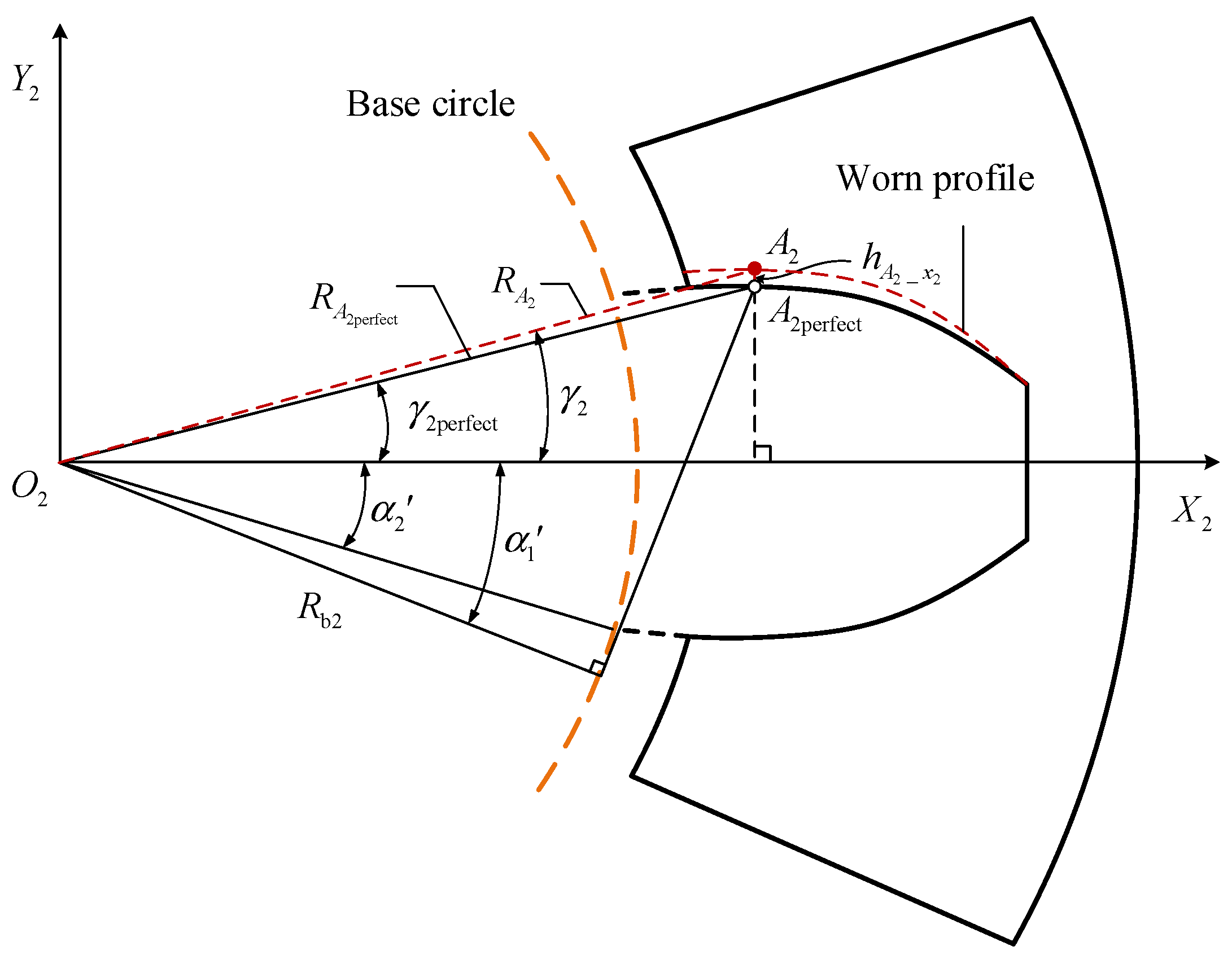
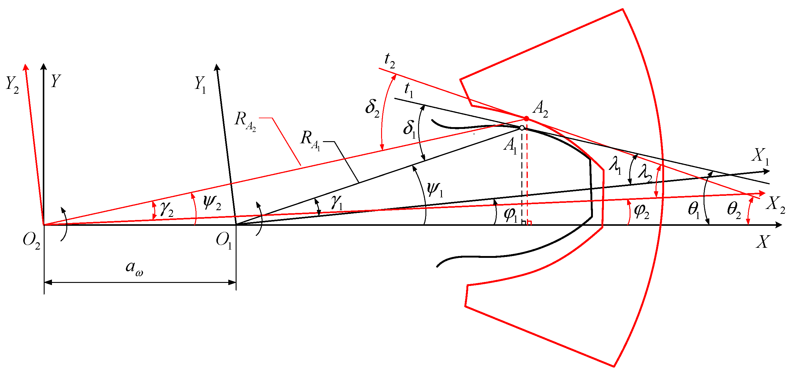
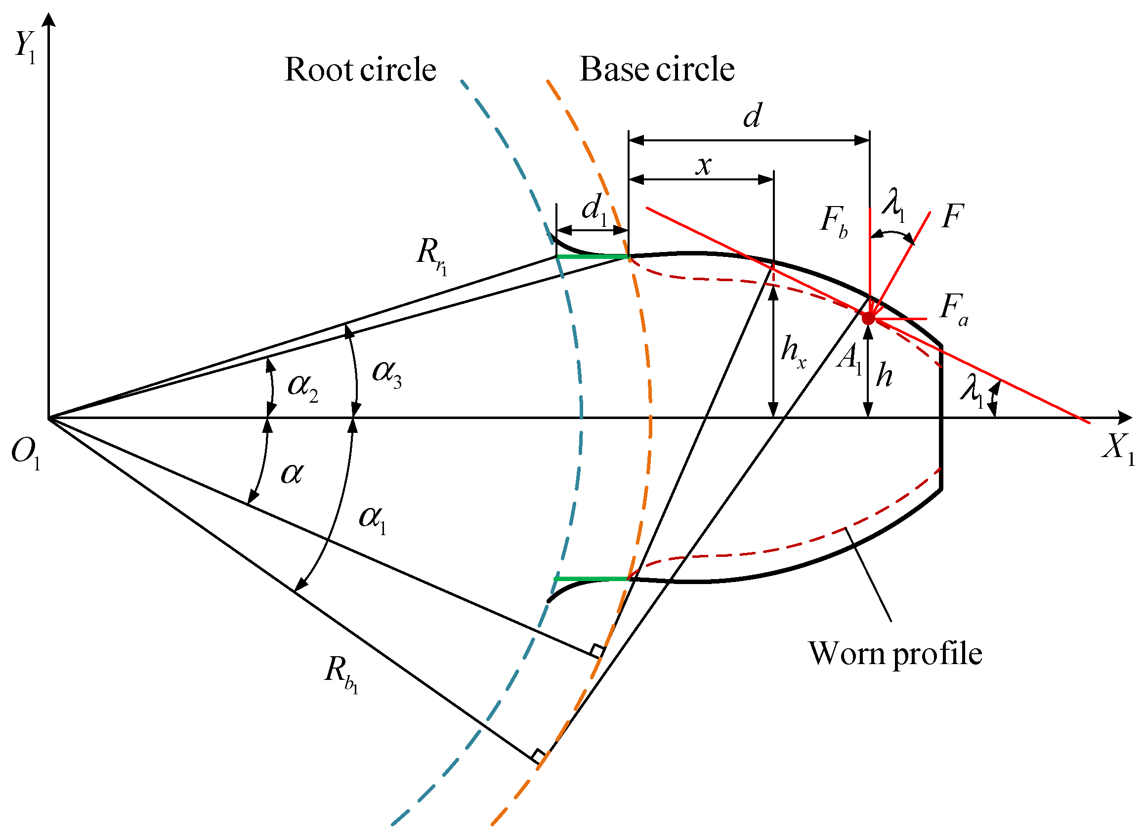
2.1. Analytical Model

Figure 2 shows the gear transmission of perfect involute internal spur gear pair, where the ideal meshing line t is tangent to the base circle of two gears at points N 1 and N 2 , respectively. Moreover, O 1 and O 2 are the rotation centers of the driving and driven gears, R b 1 and R b 2 are the base circle radii of two gears, respectively. According to the elative kinematic relation of gears, the meshing point appears on the meshing line t and moves as the gear rotates when the perfect internal spur gear pair are engaged. Generally, the meshing condition is not changed by local gear faults such as tooth crack, pitting, and spalling, which means that the meshing point on the tooth profile keeps moving along the ideal meshing line. However, tooth wear changes the tooth involute profile, resulting in the formation of a new mesh relationship when the gear pair engages. In such condition, the meshing point is not on the ideal meshing line N 1 N 2 . Therefore, it is vital to deduce a new mesh relationship describing the tooth wear of internal spur gear.
Figure 3 presents the single-tooth analytical model in the driving gear, where X 1 O 1 Y 1 denotes the local coordinate system and it rotates with the driving gear. Moreover, A 1 perfect represents the meshing point on the prefect tooth profile. When tooth wear occurs, the position of the meshing point changes from A 1 perfect to A 1 , and the wear depth between the two meshing points A 1 perfect and A 1 is h A 1 _ x 1 . In addition, R A 1 perfect and R A 1 are the corresponding radii of the two meshing points.
In the local coordinate system X 1 O 1 Y 1 , the single-tooth geometric relationships of the driving gear can be written as follows:
γ 1 perfect = arctan ( α 2 + α 1 ) α 1
R A 1 perfect = R b 1 cos ( α 1 + γ 1 perfect )
γ 1 = arctan ( R A 1 perfect sin γ 1 perfect h A 1 _ x 1 R A 1 perfect cos γ 1 perfect )
R A 1 = R A 1 perfect cos γ 1 perfect cos γ 1
where α 1 represents the angle of the perfect meshing point A 1 perfect on the prefect tooth profile, and α 2 represents the half tooth angle on the base circle. γ 1 perfect and γ 1 represent the angles that correspond to points A 1 perfect and A 1 , respectively.
As shown in Figure 4, the local coordinate system of the driven gear X 2 O 2 Y 2 rotates with the driven gear. Moreover, the meshing point on the perfect profile of the driven gear is represented by A 2 perfect , and represented by A 2 on the worn tooth profile. h A 2 _ x 2 is the wear depth between the two meshing points. R A 2 perfect and R A 2 represent the corresponding radii of the two meshing points A 2 perfect and A 2 .
Given the above definitions, the single-tooth geometric relationships of the driven gear can be expressed as follows:
γ 2 perfect = arctan ( α 2 + α 1 ) α 1
R A 2 perfect = R b 2 cos ( α 1 + γ 2 perfect )
γ 2 = arctan ( R A 2 perfect sin γ 2 perfect + h A 2 _ x 2 R A 2 perfect cos γ 2 perfect )
R A 2 = R A 2 perfect cos γ 2 perfect cos γ 2
where α 1 represents the angle of the perfect meshing point A 2 perfect on the single-tooth profile, and α 2 represents the half tooth angle on the base circle. γ 2 perfect and γ 2 represent the angles of the points A 2 perfect and A 2 , respectively.
According to the above two analytical models, the single-tooth meshing analytical model with tooth wear can be established, which is presented in Figure 5. Three coordinates X O 2 Y , X 1 O 1 Y 1 , X 2 O 2 Y 2 and two meshing points A 1 and A 2 are contained in the proposed model, in which X O 2 Y is the fixed global coordinate system, which can be established through the axis O 1 O 2 of two gears. For each gear, there is a corresponding local coordinate system rotating with, X 1 O 1 Y 1 for the driving and X 2 O 2 Y 2 for the driven gears, respectively. Additionally, t 1 and t 2 are the tangents of two meshing points.
In order to obtain the new mesh relationship of internal spur gear with tooth wear, the following geometric principles need to be satisfied:
(1)
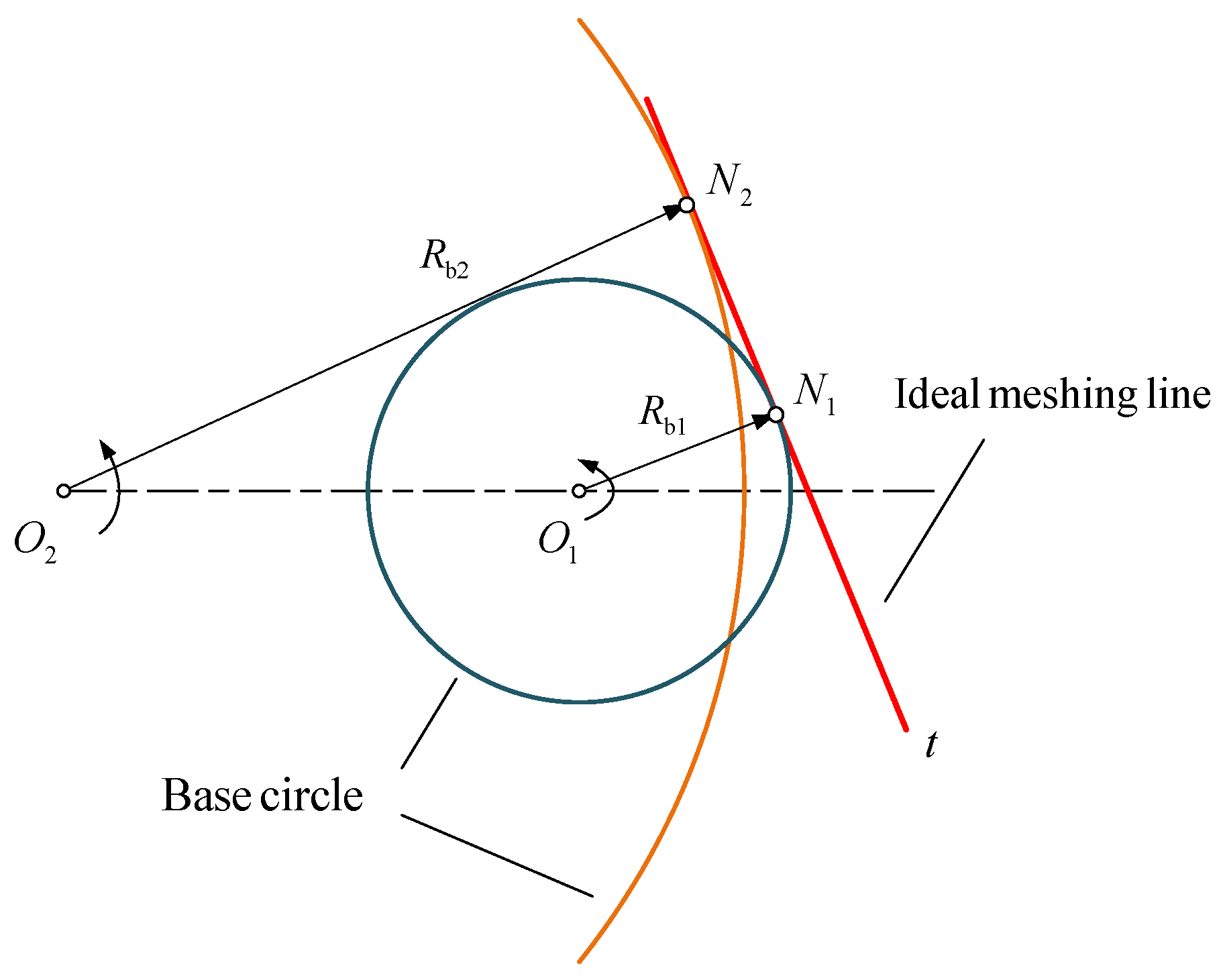
The meshing point of the driving gear moves from tooth root to tip as the gear rotates, and the driven gear is the opposite.
(2)
The gear center distance remains unchanged, which can be written as follows:
R A 2 cos ( γ 2 + φ 2 ) R A 1 cos ( γ 1 + φ 1 ) = a ω
(3)
With the meshing points A 1 and A 2 engaging, the axis Y and the tangents of two meshing points are the same, which can be expressed as:
R A 1 sin ( γ 1 + φ 1 ) = R A 2 sin ( γ 2 + φ 2 )
θ 1 = θ 2
Additionally, in order to describe the geometric relationships shown in Figure 5, there are the following formulas:
θ 1 = δ 1 ψ 1
θ 2 = δ 2 ψ 2
ψ 1 = γ 1 + φ 1
ψ 2 = γ 2 + φ 2
δ 1 = λ 1 + γ 1
δ 2 = λ 2 + γ 2
where δ 1 and δ 2 are the angles between the tangent t 1 and O 1 A 1 , the tangent t 2 and O 2 A 2 , respectively. ψ 1 denotes the angle between O 1 X and O 1 A 1 , where ψ 1 > 0 when A 1 is above O 1 X and ψ 1 < 0 when A 1 is below O 1 X . ψ 2 denotes the angle between O 2 X and O 2 A 2 , where ψ 2 > 0 when A 2 is above O 2 X and ψ 2 < 0 when A 2 is below O 2 X . θ 1 and θ 2 represent the acute angles between the tangent t 1 and O 2 X , the tangent t 2 and O 2 X , respectively. φ 1 represents the rotational angle of X 1 O 1 Y 1 relative to O 1 X , where φ 1 > 0 when the axis X 1 is above O 1 X and φ 1 < 0 when the axis X 1 is below O 1 X . φ 2 presents the rotational angle of X 2 O 2 Y 2 , where φ 1 > 0 when the axis X 2 is above O 2 X and φ 1 < 0 when the axis X 2 is below O 2 X . λ 1 and λ 2 represent the angles between the tangent t 1 and the axis X 1 and the tangent t 2 and the axis X 2 , respectively.
In addition to the axes O 1 Y 1 and O 2 Y 2 of the meshing points A 1 and A 2 , the slope of the tangents t 1 and t 2 is also changed by gear wear. In general, the relationship between slope d y 1 / d x 1 and angle λ 1 can be written as follows:
λ 1 = arctan ( d y 1 / d x 1 )
where the slope of the axis O 1 Y 1 in X 1 O 1 Y 1 can be expressed by the wear depth h A 1 _ x 1 and the perfect profile function g 1 ( x 1 ) , which can be expressed as:
{ y 1 = g 1 ( x 1 ) h A 1 _ x 1 d g 1 ( x 1 ) / d x 1 = tan α 1
Substituting Equation (19) into Equation (18), the new geometric relationship between slope d h A 1 _ x 1 / d x 1 and angle λ 1 can be obtained as:
λ 1 = arctan ( tan α 1 + d h A 1 _ x 1 / d x 1 )
Similarly, the relationship between angle λ 2 and slope d y 2 / d x 2 can be written as:
λ 2 = arctan ( d y 2 / d x 2 )
where the slope of the axis O 2 Y 2 in X 2 O 2 Y 2 can be expressed by the wear depth h A 2 _ x 2 and the perfect profile function g 2 ( x 2 ) , which can be expressed as:
{ y 2 = g 2 ( x 2 ) + h A 2 _ x 2 d g 2 ( x 2 ) / d x 2 = tan α 1
Similarly, substituting Equation (22) into Equation (21), the new geometric relationship between the slope d h A 2 _ x 2 / d x 2 and angle λ 2 can be obtained as:
λ 2 = arctan ( tan α 1 d h A 2 _ x 2 / d x 2 )
Therefore, with the established analytical model of single-tooth meshing, the new mesh relationship for internal spur gears with tooth wear can be derived. It should be noted that wear depths h A 1 _ x 1 and h A 2 _ x 2 are denoted in Equations (3) and (7), and the slopes of wear depth d h A 1 _ x 1 / d x 1 and d h A 2 _ x 2 / d x 2 are denoted in Equations (20) and (23). Next, these geometric equations are solved to acquire the new mesh relationship of internal spur gears with tooth wear.
To derive the new mesh relationship, the algorithm flow for solving the analytical model is written in detail as follow (Algorithm 1):
Algorithm 1: Algorithm of the analytical model solution
1.
Initialize geometric parameters: R b 1 ,   R b 2 ,   α 2 ,   α 2 ,   a ω ,   h A 1 _ x 1 ,   h A 2 _ x 2 ,   d h A 1 _ x 1 / d x 1 ,   d h A 2 _ x 2 / d x 2
2.
Initialize tolerable error of center distance and number of meshing points: ε a , NUM
3.
Get meshing range of the driving gear: root angle c 1 and tip angle a 1
4.
Get meshing range of the driven gear: tip angle a 2 and root angle c 2
5.
For i = 1 , 2 , , NUM
6.
 From tooth root to tip α 1 = c 1 + ( a 1 c 1 ) ( i 1 ) / ( NUM 1 )
7.
 Solve directly α 1 γ 1 perfect ,   R A 1 perfect ,   γ 1 ,   R A 1 ,   λ 1 ,   δ 1
8.
For j = 1 , 2 , , NUM
9.
    From tooth tip to root α 1 = a 2 + ( c 2 a 2 ) ( j 1 ) / ( NUM 1 )
10.
  Solve directly α 1 γ 2 perfect ,   R A 2 perfect ,   γ 2 ,   R A 2 ,   λ 2 ,   δ 2
11.
  Solve φ 1 = arctan ( R A 1 sin γ 1 + R A 2 sin ( γ 2 + λ 2 λ 1 ) R A 1 cos γ 1 R A 2 cos ( γ 2 + λ 2 λ 1 ) ) ,   φ 2 = λ 2 λ 1 + φ 1
  • ψ 1 = γ 1 + φ 1 ,   ψ 2 = γ 2 + φ 2 ,   θ 1 = δ 1 ψ 1 ,   θ 2 = δ 2 ψ 2
12.
  End For
13.
  Find corresponding meshing point: α 1 = arg min α 1 R A 2 cos ( φ 2 + γ 2 ) R A 1 cos ( γ 1 + φ 1 ) a ω 2
14.
  If R A 2 cos ( φ 2 + γ 2 ) R A 1 cos ( γ 1 + φ 1 ) a ω 2 < ε a
15.
  Get corresponding meshing point α 1 , γ 2 perfect ,   R A 2 perfect ,   γ 2 ,   R A 2 ,   λ 2 ,   δ 2
16.
  Else
17.
  Fail to get corresponding meshing point
18.
  End If
19.
End For

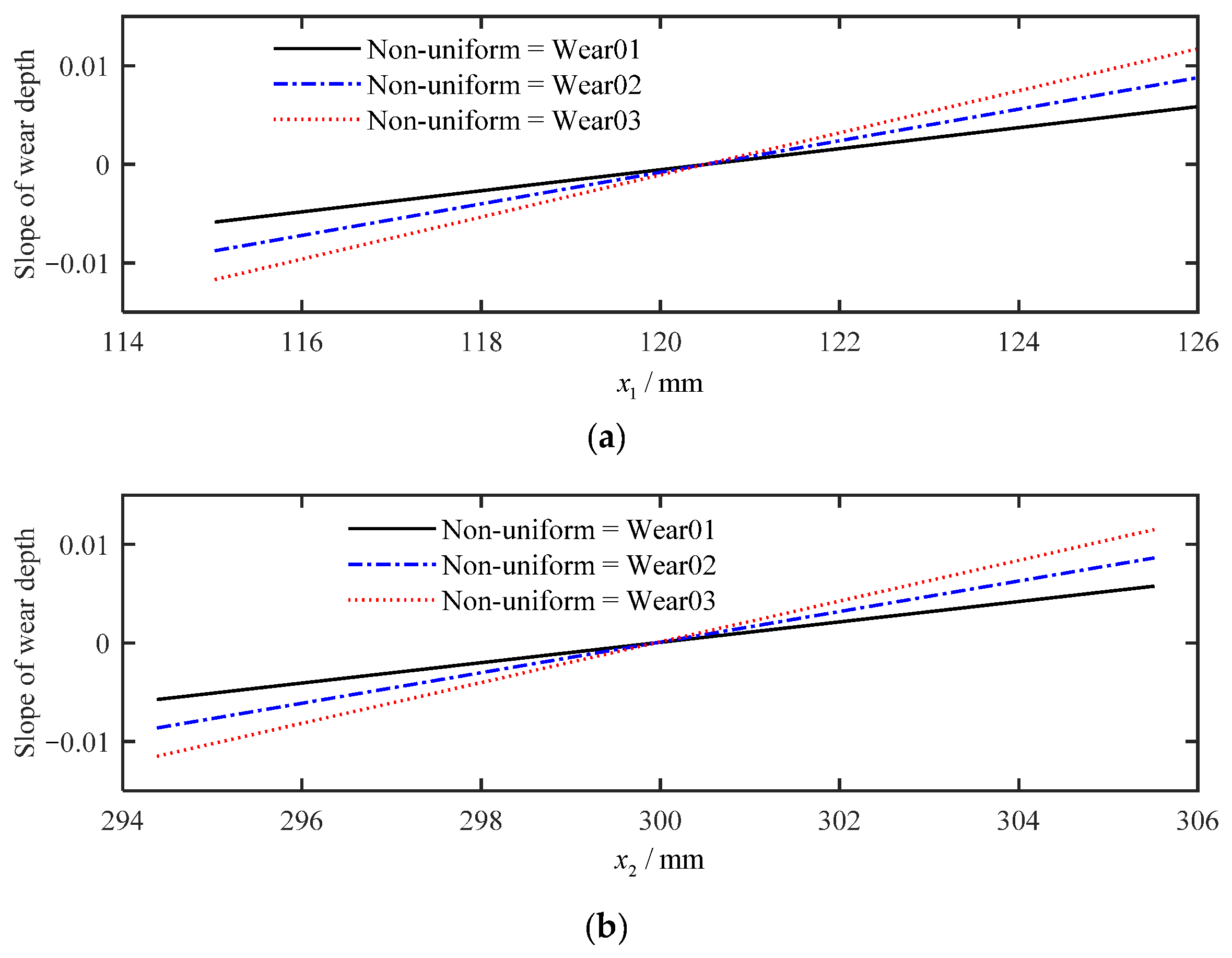
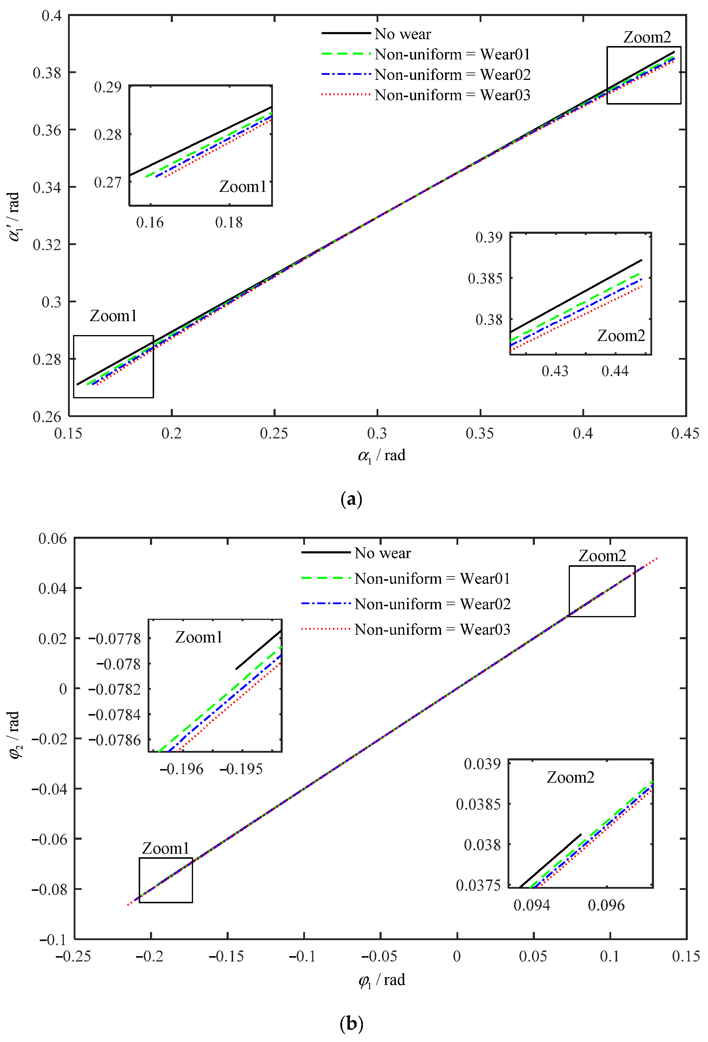
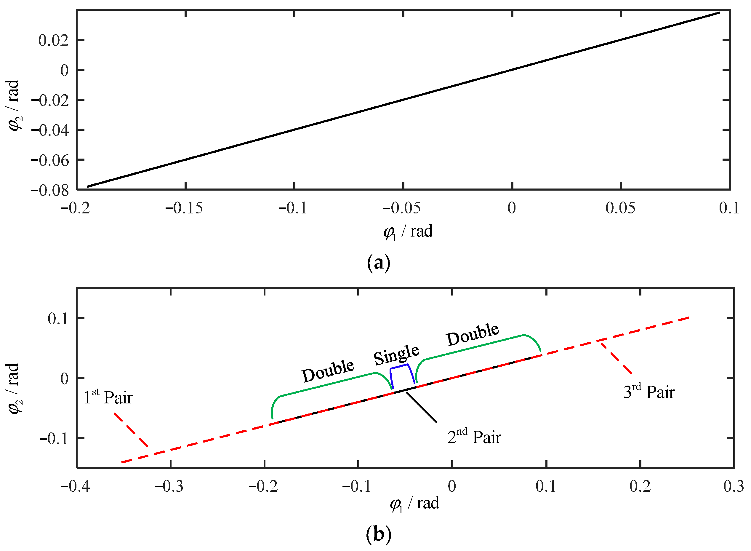
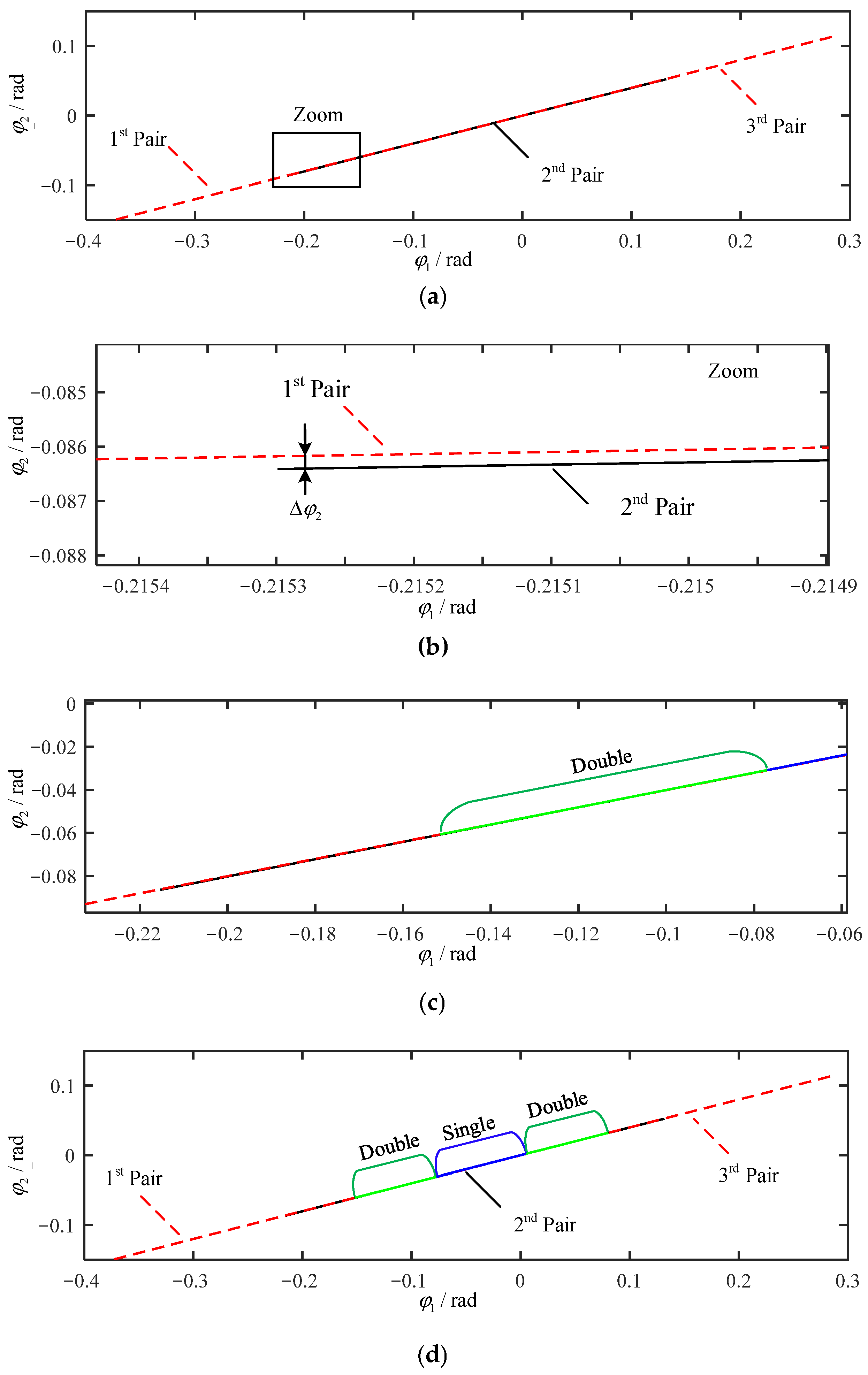
2.2. Results of Mesh Relationship with Tooth Wear

This case will introduce a new mesh relationship with non-uniform wear. Figure 6 shows the non-uniform wear on tooth profile, where non-uniform wear indicates that the wear depth of tooth profile is different, while the wear distribution for each tooth in gears is the same. In addition, Wear01, Wear02, and Wear03 are used to represent different degrees of non-uniform wear, where Wear01 is slight, Wear02 is moderate, and Wear03 is severe. It should be noted that slight, moderate, and severe wear refer only to the relative severity level among three wear conditions instead of the actual definition of wear degrees. Meanwhile, the basic parameters of internal spur gear pair employed in both cases are listed in Table 1.
Figure 7 shows different non-uniform wear depths of the driving and driven gears tooth profiles. It can be seen that the wear depth does not vary linearly from root to tip, but decreases first and then increases, which is consistent with the trend of gear wear evolution. Figure 8 depicts different slopes of non-uniform wear depth of the internal spur gear pair tooth profiles, represented by d h A 1 _ x 1 / d x 1 and d h A 2 _ x 2 / d x 2 .
Given the wear depths and the slopes obtained above, we can obtain the mesh relationship through Algorithm 1, which includes two parts: one is the position of two meshing points on the driving and driven gears tooth profiles, represented by α 1 and α 1 , and the other one is the rotational angles of driving and driven gears, represented by φ 1 and φ 2 . The results are shown in Figure 9. The influence of non-uniform wear on the single-tooth mesh relationship between α 1 and α 1 is presented in Figure 9a. Compared with the perfect condition, the tooth wear changes the meshing points position obviously and the single-tooth meshing range of α 1 and α 1 also decreases. Meanwhile, the relationship between α 1 and α 1 is no longer linear. The single-tooth mesh relationship between φ 1 and φ 2 with non-uniform wear is shown in Figure 9b. It can be observed that the rotational meshing range of φ 1 and φ 2 is increased with respect to the perfect condition, and φ 2 changes approximately linearly with φ 1 .

3. Mesh Stiffness of Internal Spur Gears with Tooth Wear

Generally speaking, gear mesh stiffness is one of the most important excitation sources for gear dynamic system. In this section, we evaluate the mesh stiffness of the internal spur gear with worn profile based on the new mesh relationship deduced in Section 2. First, the expression of single-tooth mesh stiffness for internal spur gear with tooth wear is deduced using the potential method and the new mesh relationship. Then, the multi-tooth mesh rule is proposed, and the multi-tooth mesh stiffness is calculated by superimposing the single-tooth mesh stiffness as the multi-tooth mesh rule. The results of mesh stiffness are analyzed. Finally, the mesh stiffness with tooth wear is validated by comparing it with the finite element results.

3.1. Single-Tooth Mesh Stiffness

Gear mesh stiffness is usually considered to be the main factor affecting gear dynamics with failures [24,25,26]. The influence of tooth wear on mesh stiffness will be analyzed with the use of the new mesh relationship gained in Section 2. The gear tooth is considered to be a cantilever beam, and the potential energy method is used to calculate mesh stiffness. In reference [22], the potential energy of a single tooth contains four parts: Hertzian contact energy U h , bending energy U b , shear deformation energy U s , and axial compressive energy U a , and the corresponding stiffness includes Hertzian contact stiffness k h , bending stiffness k b , shear stiffness k s , and axial compressive stiffness k a .
The internal gear pair contains external and internal gears. For external spur gears, there are two different situations in calculating mesh stiffness: Situation 1: R b 1 > R r 1 and Situation 2: R b 1 R r 1 .
In Situation 1, the base circle radius is larger than the root circle radius. Figure 10 shows the cantilever beam model for the gear tooth with wear where wear occurs on both sides of single tooth. It is worth noting that the wear depth on both sides of the gear is consistent, and the tooth wear changes both the height of tooth profile, represented by h and h x , and the action force direction, represented by λ 1 .
These parameters are derived as:
F a = F sin λ 1 ,   F b = F cos λ 1
h = R b 1 [ ( α 1 + α 2 ) cos α 1 sin α 1 ] h A 1 _ x 1
h x = R b 1 [ ( α 2 α ) cos α + sin α ] h wear _ x 1
d = R b 1 [ ( α 1 + α 2 ) sin α 1 + cos α 1 ] R b 1 cos α 2
I x = 1 12 ( 2 h x ) 3 b , A x = 2 h x b
I d 1 = 1 12 ( 2 R b 1 sin α 2 ) 3 b , A d 1 = 2 R b 1 sin α 2 b
where h wear _ x 1 denotes the wear depth at the axis X 1 . I x and A x depict the moment of inertia and the area in section x , respectively. I d 1 and A d 1 depict the moment of inertia and the area in section d 1 , respectively.
According to the potential energy theory, the relationship between the potential energy and corresponding stiffness is composed of two parts: from root circle to base circle and from base circle to the meshing point A 1 , which are expressed as:
U h = F 2 2 k h ,   k h = π E b 4 ( 1 v 2 )
U b = F 2 2 k b = 0 d [ F b ( d x ) F a h ] 2 2 E I x d x + 0 d 1 [ F b ( d + x ) F a h ] 2 2 E I d 1 d x
U s = F 2 2 k s = 0 d 1.2 F b 2 2 G A x d x + 1.2 F b 2 d 1 2 G A d 1
U a = F 2 2 k a = 0 d F a 2 2 E A x d x + F a 2 d 1 2 E A d 1
where b represents the tooth width. v represents the Poisson’s ratio. E and G represent Young’s modulus and shear modulus, respectively, and G = E / ( 2 ( 1 + v ) ) . d 1 is approximately replaced by R b 1 R r 1 .
Thus, these stiffness values are derived as follows:
1 k b = α 1 α 2 3 ( α 2 α ) cos α × D 2 2 E b H 3 d α + 0 R b 1 R r 1 [ ( d + x ) cos λ 1 h sin λ 1 ] 2 E I d 1 d x
1 k s = α 1 α 2 1.2 ( 1 + v ) ( α 2 α ) cos α cos 2 λ 1 E b H d α + 1.2 cos 2 λ 1 G A d 1 ( R b 1 R r 1 )
1 k a = α 1 α 2 ( α 2 α ) cos α sin 2 λ 1 2 E b H d α + sin 2 λ 1 E A d 1 ( R b 1 R r 1 )
where D = cos λ 1 [ ( α 1 + α 2 ) sin α 1 + cos α 1 ( α α 2 ) sin α cos α ] + sin λ 1 [ h A 1 _ x 1 / R b 1 + sin α 1 ( α 1 + α 2 ) cos α 1 ] , and H = sin α + ( α 2 α ) cos α h wear _ x 1 / R b 1 .
In addition, the foundation stiffness is derived in [27]:
1 k f = δ f F = cos 2 λ 1 E b { L ( u f S f ) 2 + M ( u f S f ) + P ( 1 + Q tan 2 λ 1 ) }
where u f = R b 1 / cos ( λ 1 ) R r 1 and reference [27] depicts these parameters L , M , P , Q in detail.
In Situation 2, the root circle radius is bigger than the base circle radius. Figure 11 shows the beam model of the single tooth with wear. Compared with Situation 1, the different geometric parameter is:
d = R b 1 [ ( α 1 + α 2 ) sin α 1 + cos α 1 ] R r 1 cos α 3
The potential energy is from the root circle to the meshing point A 1 :
U b = F 2 2 k b = 0 d [ F b ( d x ) F a h ] 2 2 E I x d x
U s = F 2 2 k s = 0 d 1.2 F b 2 2 G A x d x
U a = F 2 2 k a = 0 d F a 2 2 E A x d x
The derived stiffness values are as follows:
1 k b = α 1 α 4 3 ( α 2 α ) cos α × D 2 2 E b H 3 d α
1 k s = α 1 α 4 1.2 ( 1 + v ) ( α 2 α ) cos α cos 2 λ 1 E b H d α
1 k a = α 1 α 4 ( α 2 α ) cos α sin 2 λ 1 2 E b H d α
where D and H are the same as Situation 1. The foundation stiffness k f and Hertzian contact stiffness k h are the same in Situations 1 and 2.
As another part of internal gear pair, Figure 12 depicts the beam model of the single tooth of an internal spur gear with a worn profile. Tooth wear changes both the height of tooth profile, represented by h and h x , and the action force direction, represented by β . These parameters are derived as:
β = θ 0 + λ 2
F a = F sin β ,   F b = F cos β
h = R b 2 [ sin ( α 1 + θ 0 ) ( α 1 + α 2 ) cos ( α 1 + θ 0 ) ] h A 2 _ x 2 cos θ 0
h x = R b 2 [ sin ( α + θ 0 ) ( α + α 2 ) cos ( α + θ 0 ) ] h wear _ x 2 cos θ 0
d = R b 2 [ ( α f + α 2 ) sin ( α f + θ 0 ) + cos ( α f + θ 0 ) ( α 1 + α 2 ) sin ( α 1 + θ 0 ) cos ( α 1 + θ 0 ) ] h A 2 _ x 2 sin θ 0
x = R b 2 [ ( α f + α 2 ) sin ( α f + θ 0 ) + cos ( α f + θ 0 ) ( α + α 2 ) sin ( α + θ 0 ) cos ( α + θ 0 ) ] h wear _ x 2 sin θ 0
I x = ( 2 h x ) 3 b / 12 , A x = 2 h x b
where the angle λ 2 is obtained through the analytical model in Equation (23). h wear _ x 2 denotes the wear depth at coordinate x 2 . I x and A x depict the moment of inertia and the area in section x , respectively.
The potential energy is from the root circle to the meshing point A 2 :
U b = F 2 2 k b = 0 d [ F b ( d x ) F a h ] 2 2 E I x d x
U s = F 2 2 k s = 0 d 1.2 F b 2 2 G A x d x
U a = F 2 2 k a = 0 d F a 2 2 E A x d x
The derived stiffness values are as follows:
1 k b = α f α 1 [ [ cos ( β ) ( d x ) sin ( β ) h ] 2 E I x d x d α ] d α
1 k s = α f α 1 [ 1.2 ( cos ( β ) ) 2 G A x d x d α ] d α
1 k a = α f α 1 [ ( sin ( β ) ) 2 E A x d x d α ] d α
where d x d α = R b 2 ( α + α 2 ) cos ( α + θ 0 ) R b 2 d h wear _ x 2 d x 2 ( α 2 + α ) cos α sin θ 0 .
Through the potential energy method utilized in external and internal gears, the single-tooth stiffness for the internal spur gear is obtained, and then the single-tooth mesh stiffness with wear can be introduced. Based on the new mesh relationship with wear, the relationship between the meshing position of meshing point A 1 in the driving gear and the meshing position of corresponding meshing point A 2 in the driven gear can be obtained, denoted by α 1 and α 1 , respectively.
In general, the contact ratio of internal spur gear pair is from 1 to 2. Therefore, superimposing single-tooth stiffness of the meshing teeth, the single-tooth mesh stiffness can be deduced as follows:
k = 1 1 k h + i = 1 2 ( 1 k b i + 1 k s i + 1 k a i + 1 k f i )
where the subscripts i = 1 , 2 represent the driving gear and driven gear, respectively.
Given the same wear depths and the gear parameters as in Section 2, the single-tooth mesh stiffness with different non-uniform wear depths can be obtained as presented in Figure 13, while Figure 13a presents the single-tooth mesh stiffness of α 1 . It can be seen that tooth wear decreases the mesh stiffness and the mesh range is smaller. In addition, α 1 denotes the meshing position of the driving gear and it varies from tooth root to tooth tip, where α 1 varies from small to large. In this figure, the initial meshing position α 1 is increased and the final meshing point α 1 remains unchanged, which indicates that the single-tooth meshing range gradually decreases with the increasing wear depth. However, we usually consider the single-tooth mesh stiffness at different rotational angles. The single-tooth mesh stiffness of φ 1 is shown in Figure 13b, where φ 1 denotes the rotational angle of the driving gear. It can be seen that the single-tooth mesh stiffness of φ 1 increases significantly in both mesh-in and mesh-out stages as the depth of wear increases, which is obviously different from that of α 1 . Meanwhile, the range of rotational meshing also increases with the increase of gear wear depth.

3.2. Multi-Tooth Mesh Stiffness

3.2.1. Multi-Tooth Mesh Rule

For internal spur gears, the contact ratio is usually 1~2, which means the single-tooth and double-teeth of the gear pair alternately engage during the engagement process. In this section, the multi-tooth mesh rule which describes the meshing relationship between single and double teeth is deduced to obtain the law of gear meshing with tooth wear.
With the expressions of the new single-tooth mesh relationship deduced in Section 2.1, the mesh relationship between the driving and driven gears rotational angles can be gained, which are represented by φ 1 and φ 2 . The multi-tooth meshing can be obtained by superimposing the single-tooth meshing, and the formula can be expressed as:
{ φ 1 ( 2 nd ) = φ 1 ( 1 st ) + 2 π z 1 φ 2 ( 2 nd ) = φ 2 ( 1 st ) + 2 π z 2 ,   { φ 1 ( 3 rd ) = φ 1 ( 1 st ) + 2 × 2 π z 1 φ 2 ( 3 rd ) = φ 2 ( 1 st ) + 2 × 2 π z 2 ,   ,   { φ 1 ( n th ) = φ 1 ( 1 st ) + ( n 1 ) × 2 π z 1 φ 2 ( n th ) = φ 2 ( 1 st ) + ( n 1 ) × 2 π z 2
where n th is the nth tooth pair, and z 1 and z 2 are the tooth numbers of the driving and driven gears, respectively.
Figure 14 presents the single-tooth and multi-tooth mesh relationship when the tooth profile is prefect, in which the second gear pair single-tooth meshing is presented in Figure 14b. The meshing process consists of three parts in the multi-tooth meshing: double/single/double, in which single means that a pair of teeth mates and double indicates that two pairs of teeth mesh at the same time. Meanwhile, the multi-tooth mesh rule is proposed to acquire the multi-tooth mesh relationship of internal spur gear with tooth wear, and its two principles are as follows:
(1)
The tooth pair whose φ 2 is larger meshes first in the initial double-tooth meshing range with the increase of φ 1 .
(2)
Two tooth pairs mesh concurrently when Δ φ 2 < T h r e s h o l d for the same φ 1 where Threshold represents the threshold of the tolerable error of rotational angle.
Furthermore, the multi-tooth mesh relationship with tooth wear is presented using the multi-tooth mesh rule. The new single-tooth and multi-tooth mesh stiffness are discussed in both prefect and worn cases.

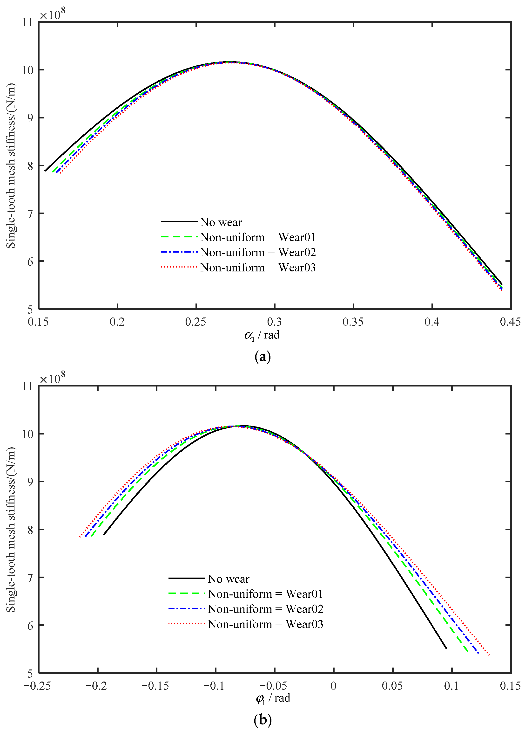
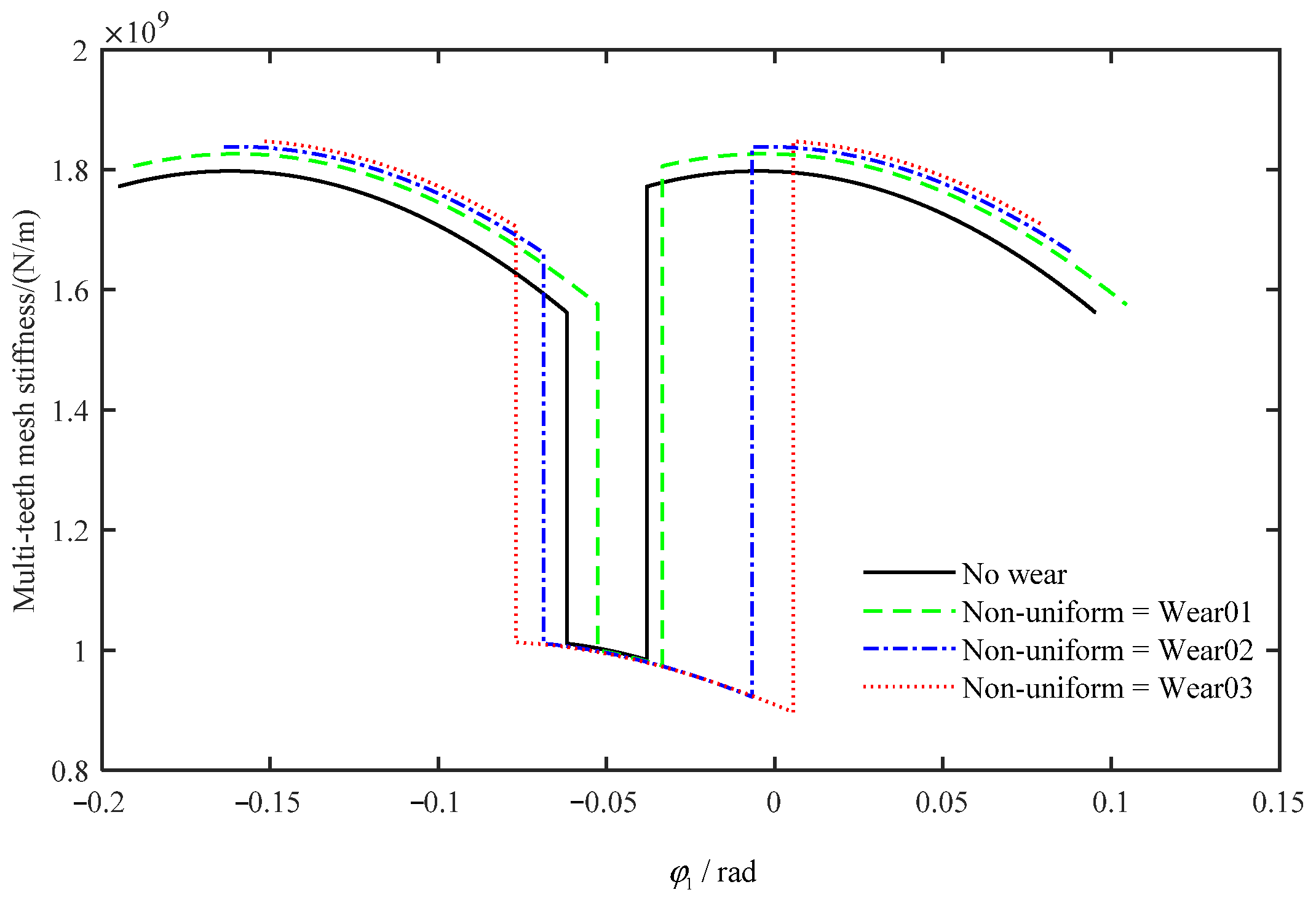
3.2.2. Results of Multi-Tooth Mesh Stiffness with Tooth Wear

Once the single-tooth mesh relationship and the multi-tooth mesh rule are gained, we can obtain the multi-tooth mesh relationship with non-uniform tooth wear. The parameters of the internal spur gears used in the simulation for calculation of multi-tooth mesh stiffness with tooth wear are given in Table 1. Taking Wear03 as an example, the results are presented in Figure 15. Figure 15a shows the mesh relationship between φ 1 and φ 2 of the first, second, and third tooth pairs. Figure 15b is the zoomed picture of Figure 15a, which depicts the meshing ranges of the first and second tooth pairs, and there is a difference Δ φ 2 between two pairs. In this paper, the Threshold in the proposed multi-tooth mesh rule is set to 10 4 rad and then the influence of tooth wear on meshing range of internal spur gear can be acquired. Figure 15c shows the new meshing range of double teeth and the meshing range of double/single/double meshing process is changed in Figure 15d. Compared to the results shown in Figure 14, the meshing range of the second tooth-pair reduces obviously, and the main reason is that when the gear suffers tooth wear, the double-tooth meshing range decreases, while that of the single-tooth increases.
The results above show that the multi-tooth mesh relationship affects the meshing range of single tooth in Section 3.1. With the new obtained single-tooth meshing range, the new single-tooth mesh stiffness is calculated, which is shown in Figure 16. The results indicate that with the degree of wear increasing, the meshing range of the new mesh stiffness decreases gradually, and correspondingly, the amplitude of the meshing stiffness increases slightly.
Therefore, the multi-tooth mesh stiffness can be evaluated by superimposing the new single-tooth mesh stiffness as the multi-tooth mesh relationship, which is written as follows:
k = i = 1 2 1 1 k h , i + 1 k b 1 , i + 1 k s 1 , i + 1 k a 1 , i + 1 k f 1 , i + 1 k b 2 , i + 1 k s 2 , i + 1 k a 2 , i + 1 k f 2 , i
where the subscript i = 1 ,   2 is the number of the meshing tooth-pair.
Figure 17 shows the multi-tooth meshing stiffness. It is clearly visible that the appearance of tooth wear mainly affects the meshing range of the mesh stiffness, in which the single-tooth meshing range decreased first and then increased with the increasing wear depth. However, the effect of tooth wear on the mesh stiffness amplitude is not significant, and only the amplitude of double-teeth meshing range is slightly increased with the increasing wear depth.

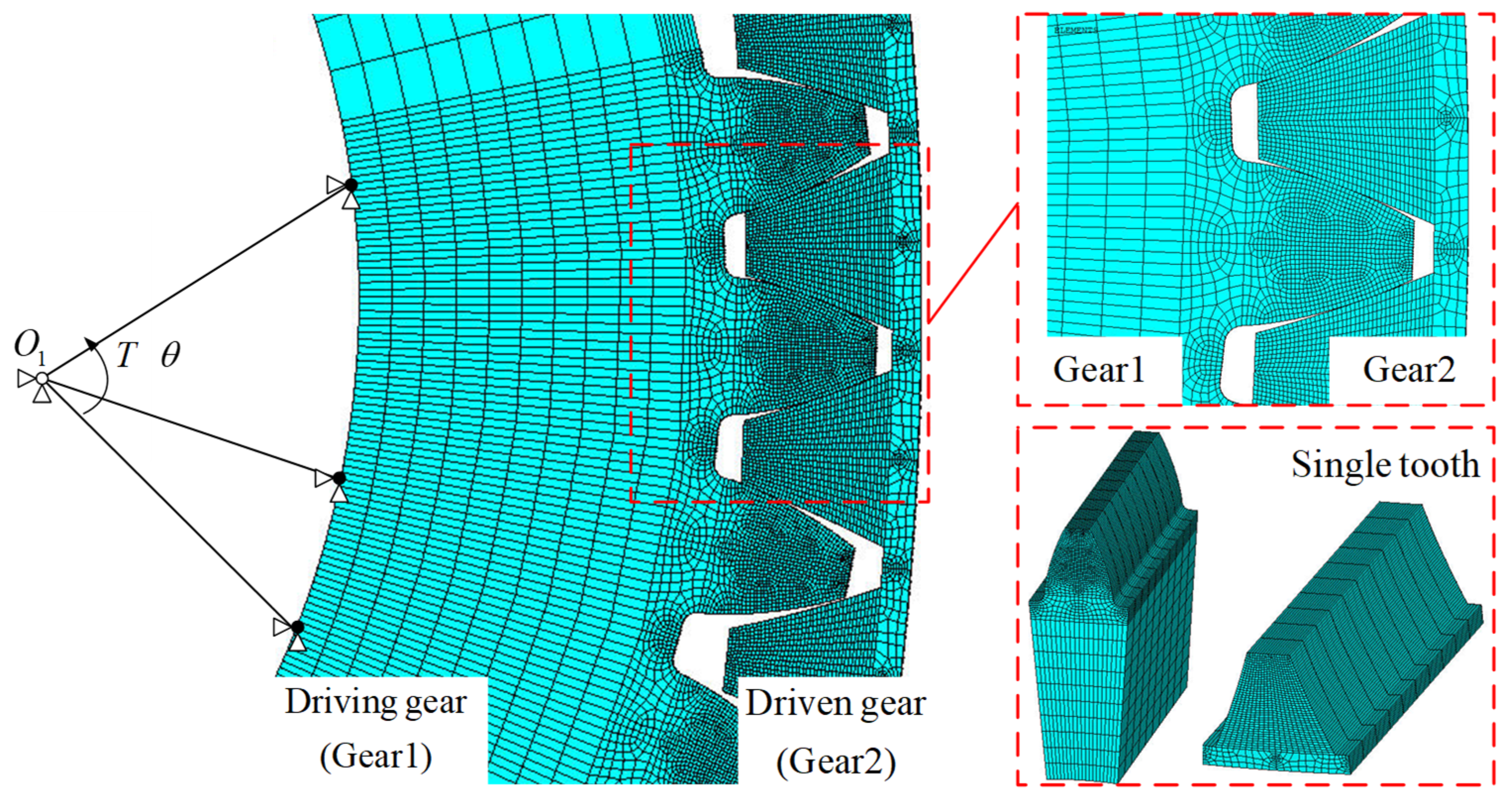
3.3. Finite Element Verification

The finite element method (FEM) is a successful strategy for evaluating the mesh stiffness, which has been widely employed in verification of the mesh stiffness of gears with defects [28,29,30,31,32]. To validate the calculated multi-tooth mesh stiffness with non-uniform wear, a finite element model using the same gear pair in Section 3.2 is established in ANSYS for result comparison and model verification. First, the three-dimensional gear models of the ring-planet gear pairs are established. Then, element type Solid185 is used to mesh the gears. The element shape is mapped hexahedral and the meshing teeth are further refined, as shown in Figure 18, to improve the precision of simulation. The shaft centers O 1 and O 2 are defined by Mass21 element and all nodes on the hub hole are fixed on corresponding shaft centers. Driving gear shaft center O 1 only has the DOF of rotation around the Z-axis and the torque T is applied to the reference node O 1 of the driving gear. Moreover, all DOFs of O 2 are constrained. In addition, a surface-to-surface contact pair (Conta174 and Targe170) is used in the finite element modeling process. Solving the finite element model, the mesh stiffness can be calculated by the following equation:
K = T R b 1 2 × θ
where θ represents the angular displacement at the node O 1 , and R b 1 is the base circle radius of the driving gear.
After finite element simulation, the multi-tooth mesh stiffness is evaluated. Figure 19 compares the mesh stiffness between the proposed method and the finite element simulation, and the wear degree is Wear03. It demonstrates that the meshing ranges of the two in the single-tooth-pair and the double-tooth-pair mesh period match well. The maximum error is 6.4% in the double-tooth meshing range and 3.2% in the single-tooth meshing range for the prefect pair, and for the worn gear pair (Wear03), the maximum error is 9.8% in the double-tooth meshing range and 4.6% in the single-tooth meshing range, and the amplitude of mesh stiffness is slightly different. Therefore, the effectiveness of the proposed method for the calculation of internal spur gear mesh stiffness with tooth wear is validated, and the analytical model of internal spur gears with non-uniform tooth wear is verified indirectly.

4. Unloaded Static Transmission Error of Internal Spur Gears with Tooth Wear

In the above theoretical derivation and verification for the analytical model of internal spur gear pair with tooth wear, the new mesh relationship is obtained and it further verifies the mesh stiffness with tooth wear. In this section, the effect of tooth wear on the unloaded static transmission error (USTE) will be studied using the new mesh relationship.
USTE is usually caused by tooth profile error, assembly error and so on, which is defined as the deviation between the theoretical position and the actual position of the driven gear under unloaded condition. This paper only considers the USTE caused by tooth wear and the expression is as follows:
e wear = R b 1 R b 2 φ 1 φ 2
Because tooth wear changes the mesh relationship, USTE also changes. According to the obtained mesh relationship between φ 1 and φ 2 of the internal spur gear, we can directly derive the USTE with wear. Furthermore, USTE is introduced in both cases.
According to the multi-tooth mesh relationship with non-uniform wear, as shown in Figure 15, we can calculate and obtain the USTE by Equation (62). The USTE of non-uniform wear is given in Figure 20, which illustrates that the USTE of the internal spur gear varies periodically as the gear pair meshing. Meanwhile, the amplitude increases obviously with the increase in wear depth.

5. Conclusions

In this paper, an analytical model for internal spur gear with tooth wear is proposed. On the basis of this, the new mesh relationship of internal spur gear pair with non-uniform wear is obtained. To deduce the multi-tooth mesh relationship, the multi-tooth mesh rule is proposed. Based on the multi-tooth mesh rule and the new mesh relationship, the influence of different wear depths on mesh stiffness and USTE is discussed. Furthermore, the mesh stiffness is verified by finite element method. Through the analysis, the main conclusions are summarized as follows:
(1)
An analytical model for internal spur gears with tooth wear is proposed, based on which the new mesh relationship of tooth wear is derived. With the proposed multi-tooth mesh rule and new mesh relationship, the evaluation method of the influence of tooth wear on mesh stiffness and USTE is presented.
(2)
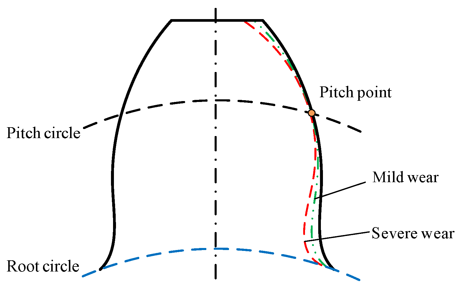
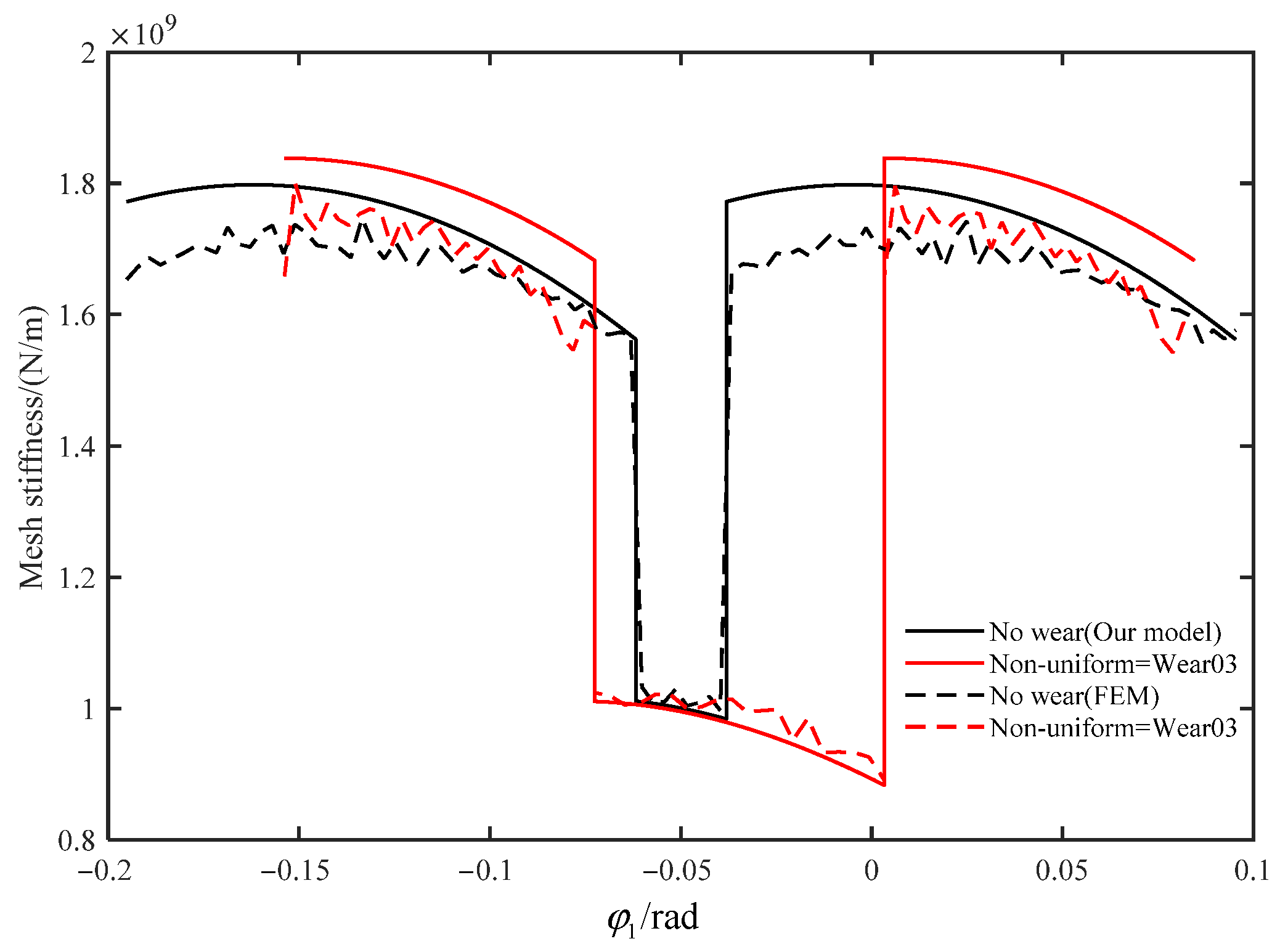
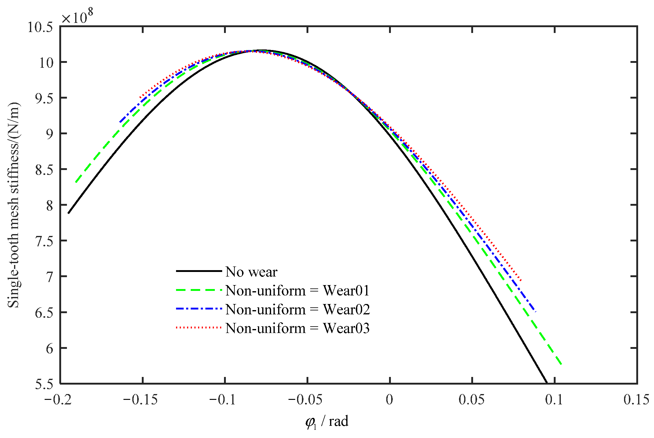
The case of non-uniform wear illustrates that tooth wear mainly affects the meshing ranges of mesh stiffness in a single tooth and double teeth and has relatively less effect on the amplitude of the meshing stiffness.
(3)
The multi-tooth mesh stiffness of the internal spur gear calculated by the proposed analytical model has been verified by the FE models. The meshing ranges of the two in single-tooth-pair and double-tooth-pair mesh period match well. The maximum error is 6.4% and 3.2% in double-tooth meshing range and single-tooth meshing range, respectively, for the prefect pair. The maximum error for the worn gear pair is 9.8% in the double-tooth meshing range and 4.6% in the single-tooth meshing range.
(4)
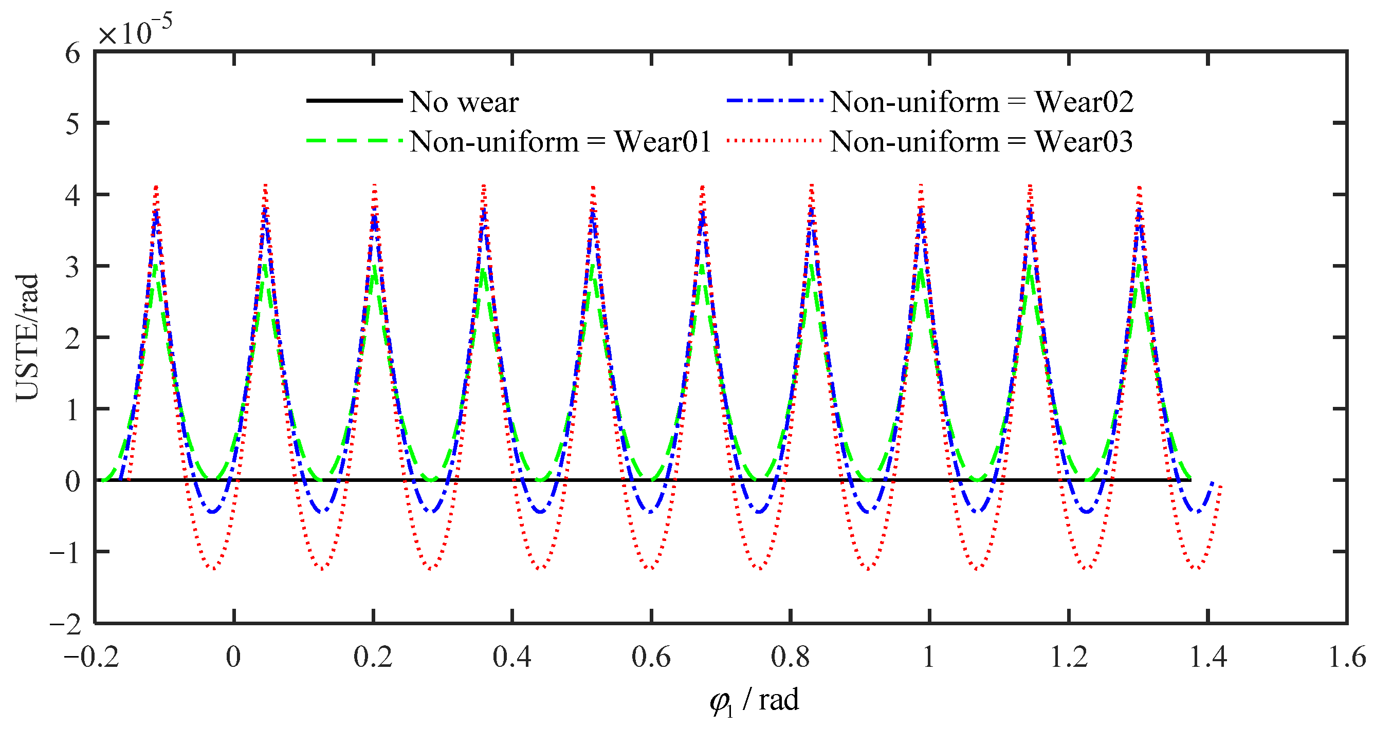
According to the new mesh relationship and multi-tooth mesh rule, USTE is comprehensively analyzed. The results indicate that the USTE varies periodically as the gear pair meshing and its amplitude grows with the increase of the wear depth. The effectiveness of the proposed model is verified by the finite element method.
Furthermore, the proposed model for the internal spur gears with tooth wear is also instructive for the dynamic modeling and analysis of the gear transmission systems of helicopters with multiple faults. These topics will be discussed in our coming works.

Author Contributions

Formal analysis, Y.W.; methodology, K.L. and Z.S.; investigation, Y.W.; validation, Z.S.; writing—original draft preparation, K.L.; writing—review and editing, B.Q.; supervision, X.C. All authors have read and agreed to the published version of the manuscript.

Funding

This research was funded by the Technical Field Funding of Foundation Strengthening Project under the grant number 2021-JCJQ-JJ-0238, the National Natural Science Foundation of China under the grant number 52075414 and the China Postdoctoral Science Foundation under the grant number No. 2021M702595.

Institutional Review Board Statement

Not applicable.

Informed Consent Statement

Not applicable.

Data Availability Statement

Not applicable.

Conflicts of Interest

The authors declare no conflict of interest.

References

  1. Flodin, A.; Andersson, S. Simulation of mild wear in spur gears. Wear 1997, 207, 16–23. [Google Scholar] [CrossRef]
  2. Flodin, A.; Andersson, S. Simulation of mild wear in helical gears. Wear 2000, 241, 123–128. [Google Scholar] [CrossRef]
  3. Bajpai, P.; Kahraman, A.; Anderson, N.E. A Surface Wear Prediction Methodology for Parallel-Axis Gear Pairs. J. Tribol. 2004, 126, 597–605. [Google Scholar] [CrossRef]
  4. Ding, H.L. Dynamic Wear Models for Gear Systems. Ph.D. Thesis, The Ohio State University, Columbus, OH, USA, 2007. [Google Scholar]
  5. Akbarzadeh, S.; Khonsari, M.M. Prediction of Steady State Adhesive Wear in Spur Gears Using the EHL Load Sharing Concept. J. Tribol. 2009, 131, 024503. [Google Scholar] [CrossRef]
  6. Osman, T.; Velex, P. Static and dynamic simulations of mild abrasive wear in wide-faced solid spur and helical gears. Mech. Mach. Theory 2010, 45, 911–924. [Google Scholar] [CrossRef]
  7. Tunalioğlu, M.; Tuç, B. Theoretical and experimental investigation of wear in internal gears. Wear 2014, 309, 208–215. [Google Scholar] [CrossRef]
  8. Wojnarowski, J.; Onishchenko, V. Tooth wear effects on spur gear dynamics. Mech. Mach. Theory 2003, 38, 161–178. [Google Scholar] [CrossRef]
  9. Kuang, J.H.; Lin, A.D. The Effect of Tooth Wear on the Vibration Spectrum of a Spur Gear Pair. J. Vib. Acoust. 2001, 123, 311–317. [Google Scholar] [CrossRef]
  10. Yuksel, C.; Kahraman, A. Dynamic tooth loads of planetary gear sets having tooth profile wear. Mech. Mach. Theory 2004, 39, 695–715. [Google Scholar] [CrossRef]
  11. Wu, S.; Zhang, H.; Wang, X.; Peng, Z.; Yang, K.; Zhu, W. Influence of the backlash generated by tooth accumulated wear on dynamic behavior of compound planetary gear set. Proc. Inst. Mech. Eng. Part C J. Mech. Eng. Sci. 2016, 231, 2025–2041. [Google Scholar] [CrossRef]
  12. Lundvall, O.; Klarbring, A. Prediction of Transmission Error in Spur Gears as a Consequence of Wear. Mech. Struct. Mach. 2001, 29, 431–449. [Google Scholar] [CrossRef]
  13. Atanasiu, V.; Oprişan, C.; Leohchi, D. The Effect of Tooth Wear on the Dynamic Transmission Error of Helical Gears with Smaller Number of Pinion Teeth. Appl. Mech. Mater. 2014, 657, 649–653. [Google Scholar] [CrossRef]
  14. Chin, Z.Y.; Smith, W.A.; Borghesani, P.; Randall, R.B.; Peng, Z. Absolute transmission error: A simple new tool for assessing gear wear. Mech. Syst. Signal Process. 2021, 146, 107070. [Google Scholar] [CrossRef]
  15. Feng, K.; Smith, W.A.; Borghesani, P.; Randall, R.B.; Peng, Z. Use of cyclostationary properties of vibration signals to identify gear wear mechanisms and track wear evolution. Mech. Syst. Signal Process. 2021, 150, 107258. [Google Scholar] [CrossRef]
  16. Choy, F.; Polyshchuk, V.; Zakrajsek, J.; Handschuh, R.; Townsend, D. Analysis of the effects of surface pitting and wear on the vibration of a gear transmission system. Tribol. Int. 1996, 29, 77–83. [Google Scholar] [CrossRef]
  17. Yesilyurt, I.; Gu, F.; Ball, A.D. Gear tooth stiffness reduction measurement using modal analysis and its use in wear fault severity assessment of spur gears. NDT E Int. 2003, 36, 357–372. [Google Scholar] [CrossRef]
  18. Liu, X.; Yang, Y.; Zhang, J. Investigation on coupling effects between surface wear and dynamics in a spur gear system. Tribol. Int. 2016, 101, 383–394. [Google Scholar] [CrossRef]
  19. Huangfu, Y.; Zhao, Z.; Ma, H.; Han, H.; Chen, K. Effects of tooth modifications on the dynamic characteristics of thin-rimmed gears under surface wear. Mech. Mach. Theory 2020, 150, 103870. [Google Scholar] [CrossRef]
  20. Brethee, K.F.; Zhen, D.; Gu, F.; Ball, A.D. Helical gear wear monitoring: Modelling and experimental validation. Mech. Mach. Theory 2017, 117, 210–229. [Google Scholar] [CrossRef]
  21. Chen, W.; Lei, Y.; Fu, Y.; Hou, L. A study of effects of tooth surface wear on time-varying mesh stiffness of external spur gear considering wear evolution process. Mech. Mach. Theory 2021, 155, 104055. [Google Scholar] [CrossRef]
  22. Shen, Z.; Qiao, B.; Yang, L.; Luo, W.; Chen, X. Evaluating the influence of tooth surface wear on TVMS of planetary gear set. Mech. Mach. Theory 2019, 136, 206–223. [Google Scholar] [CrossRef]
  23. Shen, Z.; Qiao, B.; Yang, L.; Luo, W.; Yang, Z.; Chen, X. Fault mechanism and dynamic modeling of planetary gear with gear wear. Mech. Mach. Theory 2021, 155, 104098. [Google Scholar] [CrossRef]
  24. Liang, X.; Zuo, M.J.; Pandey, M. Analytically evaluating the influence of crack on the mesh stiffness of a planetary gear set. Mech. Mach. Theory 2014, 76, 20–38. [Google Scholar] [CrossRef]
  25. Ma, H.; Pang, X.; Feng, R.; Song, R.; Wen, B. Fault features analysis of cracked gear considering the effects of the extended tooth contact. Eng. Fail. Anal. 2015, 48, 105–120. [Google Scholar] [CrossRef]
  26. Huangfu, Y.; Chen, K.; Ma, H.; Li, X.; Han, H.; Zhao, Z. Meshing and dynamic characteristics analysis of spalled gear systems: A theoretical and experimental study. Mech. Syst. Signal Process. 2020, 139, 106640. [Google Scholar] [CrossRef]
  27. Chaari, F.; Fakhfakh, T.; Haddar, M. Analytical modelling of spur gear tooth crack and influence on gear mesh stiffness. Eur. J. Mech. A Solids 2009, 28, 461–468. [Google Scholar] [CrossRef]
  28. Ma, H.; Li, Z.; Feng, M.; Feng, R.; Wen, B. Time-varying mesh stiffness calculation of spur gears with spalling defect. Eng. Fail. Anal. 2016, 66, 166–176. [Google Scholar] [CrossRef]
  29. Lei, Y.; Liu, Z.; Wang, D.; Yang, X.; Liu, H.; Lin, J. A probability distribution model of tooth pits for evaluating time-varying mesh stiffness of pitting gears. Mech. Syst. Signal Process. 2018, 106, 355–366. [Google Scholar] [CrossRef]
  30. El Yousfi, B.; Soualhi, A.; Medjaher, K.; Guillet, F. New approach for gear mesh stiffness evaluation of spur gears with surface defects. Eng. Fail. Anal. 2020, 116, 104740. [Google Scholar] [CrossRef]
  31. Wang, X.; Yang, Y.; Wang, W.; Chi, W. Simulating coupling behavior of spur gear meshing and fatigue crack propagation in tooth root. Int. J. Fatigue 2020, 134, 105381. [Google Scholar] [CrossRef]
  32. Wu, J.; Yang, Y.; Wang, P.; Wang, J.; Cheng, J. A novel method for gear crack fault diagnosis using improved analytical-FE and strain measurement. Measurement 2020, 163, 107936. [Google Scholar] [CrossRef]
Figure 1. Perfect and worn profile of internal spur gear.
Applsci 13 02022 g001
Figure 2. Gear kinematic relation for perfect involute internal spur gears.
Applsci 13 02022 g002
Figure 3. Analytical model of single tooth in the driving gear.
Applsci 13 02022 g003
Figure 4. Analytical model of single tooth in the driven gear.
Applsci 13 02022 g004
Figure 5. Analytical model of singe-tooth meshing with tooth wear.
Applsci 13 02022 g005
Figure 6. Diagram of non-uniform wear.
Applsci 13 02022 g006
Figure 7. Non-uniform wear depths on tooth profile: (a) driving gear; (b) driven gear.
Applsci 13 02022 g007
Figure 8. Non-uniform wear depth slopes on tooth profile: (a) driving gear; (b) driven gear.
Applsci 13 02022 g008
Figure 9. Single-tooth mesh relationship with non-uniform wear: (a) relationship between α 1 and α 1 ; (b) relationship between φ 1 and φ 2 .
Applsci 13 02022 g009
Figure 10. Beam model for single tooth with worn profile when base circle is larger than root circle.
Applsci 13 02022 g010
Figure 11. Beam model for single tooth with worn profile root circle is bigger than base circle.
Applsci 13 02022 g011
Figure 12. Beam model of single tooth in internal spur gear with worn profile.
Applsci 13 02022 g012
Figure 13. Single-tooth mesh stiffness with different non-uniform wear depths: (a) tooth angle α 1 ; (b) rotational angle.
Applsci 13 02022 g013
Figure 14. Tooth mesh relationship with perfect tooth profile: (a) single-tooth; (b) multi-tooth.
Applsci 13 02022 g014
Figure 15. Multi-tooth mesh relationship with non-uniform wear (Wear03): (a) multi-tooth; (b) zoom of (a); (c) double-tooth meshing range of (b); (d) double/single/double meshing range.
Applsci 13 02022 g015
Figure 16. Single-tooth mesh stiffness with the new single-tooth mesh relationship.
Applsci 13 02022 g016
Figure 17. Multi-tooth mesh stiffness with non-uniform wear.
Applsci 13 02022 g017
Figure 18. Finite element model of internal gear pair.
Applsci 13 02022 g018
Figure 19. Comparisons of the mesh stiffness between the theoretical calculation and the FEM simulation.
Applsci 13 02022 g019
Figure 20. USTE of non-uniform wear with different wear depths.
Applsci 13 02022 g020
Table 1. The parameters of internal spur gear pair.
ItemsDriving/Driven GearItemsDriving/Driven Gear
Tooth number40/100Base circle radius (mm)112.8/281.9
Tooth width (mm)50Root circle radius (mm)112.5/307.5
Pressure angle (°)20Center distance (mm)180
Module (mm)6Tooth root angle (rad)0.1540/0.3872
Poisson’s ratio0.3Tooth tip angle (rad)0.4444/0.0542
Young’s modulus (Pa)2.05 × 10¹¹Number of meshing points1849
Disclaimer/Publisher’s Note: The statements, opinions and data contained in all publications are solely those of the individual author(s) and contributor(s) and not of MDPI and/or the editor(s). MDPI and/or the editor(s) disclaim responsibility for any injury to people or property resulting from any ideas, methods, instructions or products referred to in the content.

