Article

Deformation Characteristics and Grouting Control Technology of Reused Roadway in a Fully Mechanized Coalface with Large Mining Height

1
School of Mechanics and Civil Engineering, China University of Mining and Technology-Beijing, Beijing 100083, China
2
State Key Laboratory of Coal Resources and Safe Mining, China University of Mining and Technology-Beijing, Beijing 100083, China
3
Key Laboratory of Shale Gas and Geoengineering, Institute of Geology and Geophysics, Chinese Academy of Sciences, Beijing 100029, China
4
College of Earth and Planetary Sciences, University of Chinese Academy of Sciences, Beijing 100049, China
*
Authors to whom correspondence should be addressed.
Appl. Sci. 2023, 13(3), 1951; https://doi.org/10.3390/app13031951
Submission received: 20 December 2022 / Revised: 29 January 2023 / Accepted: 31 January 2023 / Published: 2 February 2023
(This article belongs to the Special Issue Advances in Tunnel and Underground Construction)

Abstract

:
Reused roadways are increasingly adopted in fully mechanized coalfaces with large mining heights because of the ventilation and gas drainage problems. However, the forced mechanism and grouting control technology of the reused roadway was seldom studied. Hence, in this paper, field monitoring and numerical simulation were undertaken to investigate the distribution of stress and deformation of the reused roadway, and the reasonable grouting opportunities and technological parameters were determined accordingly. Engineering application of grouting control technology with self-developed inorganic double-fluid grouting materials was conducted. The field monitoring and numerical simulation revealed that the reused roadway was significantly affected by the lateral abutment pressure during the first mining operation and by the leading abutment pressure during the second mining operation. It was characterized by lagging stable deformation during the first mining operation and ceaselessly increasing deformation during the second mining operation. The deformation range of the reused roadway during the first mining operation can be divided into three stages: initial deformation, violent deformation and plateaued deformation, while the deformation range can be divided into three distinct stages: initial deformation, slow deformation and violent deformation during the second mining operation. On the basis of the roadway deformation law, two grouting opportunities were confirmed. The first grouting opportunity was suggested in the front part of the plateaued deformation stage during the first mining. The second grouting opportunity was suggested in the slow deformation stage during the second mining. Field engineering applications showed that both the deformation range and value of the reused roadway were decreased obviously after grouting.

1. Introduction

China is rich in coal resources and has extensive coal mining activities [1,2,3]. In recent decades, the fully mechanized technology with large mining height has become one of the main mining technologies for 3.5–5.0 m thick coal seams because of large yield, high efficiency and simple roadway layout [4]. This technology has been successfully improved and applied to coal seams with thicknesses more than 5.0 m in China and overseas [5,6]. However, serious problems, such as roadway deformation and gas accumulation, have been aggravated because of high mining intensity and intense mining pressure [7].
The problem of roadway deformation and damage has attracted more and more attention from experts and scholars [8,9,10]. The deformation and damage characteristics of roadways were analyzed by field monitoring, numerical simulation and physical simulation [11,12]. The destruction and failure reasons of roadways were discussed in different situations, such as in coal seams, in soft rocks or in complex geologically conditions [13,14]. Zang et al. used numerical simulation and field observation methods to analyze the cracking process of the surrounding rock in the radial direction of the roadway [15]. Chen et al. discussed the stress and deformation fields of the surrounding rock not only in the radial direction but also axial direction of deep roadways by numerical simulation [16]. Zhang et al. studied the abutment pressure distribution law of super large mining height coalfaces [17]. Besides this, the width of protective coal pillar in the front and side of coalface was optimized via researching the advanced and lateral abutment pressure [18,19]. It can be seen that the distribution features of abutment pressure have a significant impact on the deformation and failure of roadway adjacent to the coalface. Many underground coal mines have adopted a “multi-roadway layout” in large mining height coalfaces for the purpose of solving the transportation and gas problems [20,21]. Generally, the reused roadway would be reserved after the first mining for the ventilation of the second coalface. The reused roadway has to undergo two mining disturbances in the whole service period. Therefore, the deformation and roadway damage can be extensive and uncontrollable. It is necessary to research the deformation law and control technology of the reused roadway. The damage features, deformation law, plastic zone evolution of roadway under primary and secondary mining conditions were discussed previously [22,23,24]. However, some coal mines adopted not only one reused roadway. For instance, Sihe coal mine in Shanxi Province set two reused roadways the during mining process. In addition to the protective coal pillar between the coalface and roadway, there was also a protective coal pillar between the two reused roadways. The complicated conditions and stress superposition inevitably caused serious roadway deformation, but relevant studies were lacking.
Furthermore, with the gradual maturity of grouting technology, it has been found that reasonable grouting technology can improve the strength and stability of roadway-surrounding rock, and control the roadway deformation effectively. More and more scholars began to study grouting materials, and the grouting technology was widely applied in coal mines or other engineering applications [25,26,27,28]. By using experimental means, it was revealed that grouting could raise the residual strength of broken rock [29]. Various grouting materials emerged. For example, a polymer foam grouting material for strengthening broken coal was developed [30]. Besides, a new grouting material based on magnesium phosphate cement was developed [31]. In recent years, great progress has been made in the combination of grouting and roadway support technology. For example, a yielding bolt-grouting support applied to a soft-rock roadway was designed [32]. In addition, a backfilled chemical grouting material consisting mainly of cement and sodium silicate was used to improve the support effect of traditional U-shaped steel sets. Based on this, the applied effect of cement and sodium silicate was evaluated by numerical simulation [33].
As can be seen from the above, there has been great progress in the research of grouting reinforcement of roadway-surrounding rock, but the existing literature mainly focuses on the grouting materials, performance improvement and universal grouting mechanism. However, different field projects have their special site conditions and engineering problems. The temporal and spatial evolution of roadway deformation is vital in grouting projects [34]. There are still many issues to be further explored. For a field project, the grouting control technology, such as material, grouting opportunity, and technical parameters, all should be adjusted to satisfy specific engineering requirements. Meanwhile, the geological environment of underground engineering is complex and diverse. The selection of grouting materials and technology is also affected by different geological conditions. Obviously, faults, collapsed columns, water-bearing strata and so on all put forward higher requirements of grouting materials and technology.
This paper takes the reused roadway in Sihe coal mine as the background. The remainder of this paper is organized as follows. The engineering background is described in Section 2. The analysis of deformation characteristics and forced mechanism of the reused roadway are discussed in Section 3 using field monitoring and FLAC3D numerical simulation. The grouting control technology including reasonable material properties, grouting opportunities, technological parameters and the engineering applications is stated in Section 4. The conclusions are finally summarized in Section 5.

2. Engineering Background

2.1. Basic Condition and Roadway Layout of Coalface W 2302

Jincheng Coal mining group Co., Ltd. in Shanxi Province has been vigorously promoting the fully mechanized mining technology with large mining heights in recent years, of which Sihe coal mine is the most representative. To solve the production and gas problem, the “multi-roadway layout” was used in the fully mechanized coalface with a large mining height. The reused roadway would be reserved after the first coalface mining and continue to serve during the second coalface mining.
The fully mechanized coalface W 2302 with large mining height is located in the west panel 2 of Sihe coal mine. The #3 coal seam of Shanxi formation was mined. The length of coalface W 2302 is 221.5 m and the length along the strike is 1250.9 m. The widths of the coal pillars between the roadways are all 40 m, except the pillar between roadway W 23025 and W 23021 was 25 m wide. The average mining height is 5.92 m and the average dip angle is 4°. The coalface elevation is 244–280 m, and the ground elevation is 660–780 m.
The coalface W 2302 used a “three-in and two-out” roadway layout. There are five mining roadways in total (Figure 1): W 23021, W 23025, W 23023 are intake roadways, and W 23022, W 23024 are ventilation roadways. Roadways W 23021 and W 23025 were reused roadways. They were retained after the mining of coalface W 2301 (last coalface). The roadways all have a rectangular cross section with a size of 5.0 m × 3.8 m. This paper takes roadway W 23021 as the research object.

2.2. Lithology of the Roof and Floor

The false roof of the coalface is a grayish black mudstone layer with thickness of 0.2 m, which is soft and falls off with mining. The immediate roof is a gray–black sandy mudstone layer with a thickness of 4.16 m, containing plant fossils. The basic roof is a dark gray medium-grained sandstone layer with a thickness of 3.4 m. The immediate bottom is a gray–black sandy mudstone layer with a thickness of 9.37 m, containing plant fossils. The basic bottom is a fine-grained sandstone layer with thickness of 1.95 m, and it is partly sandwiched with thin sandy mudstone (Figure 2).

2.3. Support Situation of Roadway W 23021

The support scheme is illustrated in Figure 3.
  • Roof support: There are six anchor bolts Φ 22-M 24-2400 in each row. The adjacent-spacing is 850 mm or 900 mm and the row-spacing is 1000 mm. The roof cable used was a Φ 22-7300-1 high-strength anchor cable, arranged two cables per row. The anchors were fixed along the entire length, and the diameter of the anchor holes was 32~38 mm. The adjacent-spacing is 1800 mm and the row-spacing is 2000 mm. The roof surface was covered by series of metal meshes. The size of each metal mesh is 6.0 × 1.1 m.
  • Two sides support: There are four anchor bolts Φ 18-M 20-2000 in each side. The anchors were fixed along the entire length, and the diameter of the anchor holes was about 28 mm. The adjacent-spacing is 900 mm and the row-spacing is 1000 mm. The surface was covered by series of metal meshes, whose size is 3.5 × 1.1 m.

3. Deformation Characteristics and Forced Mechanism of Roadway W 23021

In this section, field monitoring and numerical simulations were conducted in order to study the deformation and stress evolution of the reused roadway. This is conducive to the following discussion of grouting control technology.

3.1. Field Monitoring

The surface displacement of the reused roadway W 23021 was monitored by the “Crossing” station method. The curves of floor-to-roof convergency, roof subsidence, floor heave and two sides’ convergency during two mining operations were drawn and discussed. The deformation characteristics of the reused roadway W 23021 were analyzed in this section.

3.1.1. Monitoring Scheme

An underground survey is important for the safety of coal mines. The surface displacement of the roadway is an effective index to describe the roadway deformation. The surface displacement of the reused roadway W 23021 was monitored by “Crossing” station method [35,36]. The stations were arranged on several cross sections and the layout is shown in Figure 4. Wooden wedges were nailed into the midpoint of the roof, floor and the two sides of the roadway as marks. During each observation, a rope was pulled between the roof and floor of the roadway and the two sides to read the distance between the roof and floor, the distance between the two sides and the distance from the center of the roadway to the roof and floor, respectively.

3.1.2. Roadway Deformation during the First Mining

The deformation curves of the reused roadway W 23021 during the first mining are shown in Figure 5. The abscissa is the distance from the coalface to the monitoring section (negative value means the monitoring section is in front of the coalface, positive value means the monitoring section is behind of the coalface), and the ordinate is the monitoring value of roadway surface displacement.
It can be found from Figure 5 that the roadway deformation curves during the first mining operation are characterized by significant lagging stable deformation, which means a permanent deformation is achieved only after coalface has advanced and passed a long distance. The two sides’ convergency was greater than the floor-to-roof convergency. The roadway deformation can be divided into three stages: ① initial deformation stage. The range is from 80 m to 30 m ahead of the coalface (−80~−30 m). The roadway was in the stage of slight deformation, during which the plastic zone of roadway begins to evolve. ② Violent deformation stage. The range was from 30 m ahead of the coalface to 200 m behind the coalface (−30~200 m). The overlying strata of the caving zone fell down during mining and formed goaf. The overlying strata in the goaf only rely on the coal pillars on both sides, which led to the increased stress in the coal pillars and the sharply increased in the deformation and velocity value of roadway. The roadway deformation velocity was the greatest in this process, and the floor heave and sidewall convergency phenomena are serious. ③ Plateaued deformation stage. The range was from 200 m to 320 m behind the coalface (200~320 m). The roadway deformation velocity decreased. The roadway deformation tends to be stationary due to gradually stabilized goaf. The maximum of two sides’ convergency was about 1200 mm, and the maximum of floor-to-roof convergency was about 820 mm.

3.1.3. Roadway Deformation during the Second Mining

The deformation curves of the reused roadway W 23021 during the second mining are shown in Figure 6.
It can be found from Figure 6 that both the surface displacement and its velocity in roadway W 23021 during the second mining operation increase gradually with the approaching of the coalface, which means the deformation becomes more and more severe with the advancement of the coalface. The two sides’ convergency was also greater than the floor-to-roof convergency. The roadway deformation can be divided into three stages: ① Initial deformation stage. The range was from 110 m to 55 m ahead of the coalface (−110~−55 m). The roadway deformation and velocity were all slight in this stage. ② Slow deformation stage. The range was from 55 m to 25 m ahead of the coalface (−55~−25 m). The roadway deformation and velocity were all greater than the previous stage, but the growth rate was slow. ③ Violent deformation stage. The range was from 25 m ahead of the coalface to the coalface position (−25~0 m). The curves’ slope obviously increased, and the velocity increased sharply. The maximum of two sides’ convergency was about 750 mm, and the maximum of floor-to-roof convergency was about 580 mm.
According to field monitoring results, when the first coalface W 2301 advanced, the deformation range of the reused roadway started from 80 m ahead of coalface and kept increasing until 320 m, behind the coalface (−80~320 m). The lagging stable deformation characteristics during the first mining operation are significant, and a permanent deformation can eventually be achieved and be kept stable. Whereas, when the second coalface W 2302 advanced, the deformation range of the reused roadway starts from 110 m ahead of the coalface and keeps increasing ceaselessly until abandoned. The deformation of the reused roadway has a distinct trend during the two mining operations. Nevertheless, it is noticed that the two sides’ convergency is greater than the floor-to-roof convergency in both mining operations, which means the deformation mechanism was similar during the two mining operations.

3.2. Numerical Simulation

As we well know, spatial numerical modeling is commonly used in underground hard coal mining, in particular in the rock mass, which is characterized by discontinuities in the form of faults [37]. In this section, a numerical simulation was performed using FLAC3D software in order to demonstrate the deformation characteristics during two mining operations. The stress distribution contours and their evolution due to coalface advancing were obtained and discussed. The forced mechanism of the reused roadway W 23021 was analyzed in this section so as to explain the causes of such deformation characteristics.

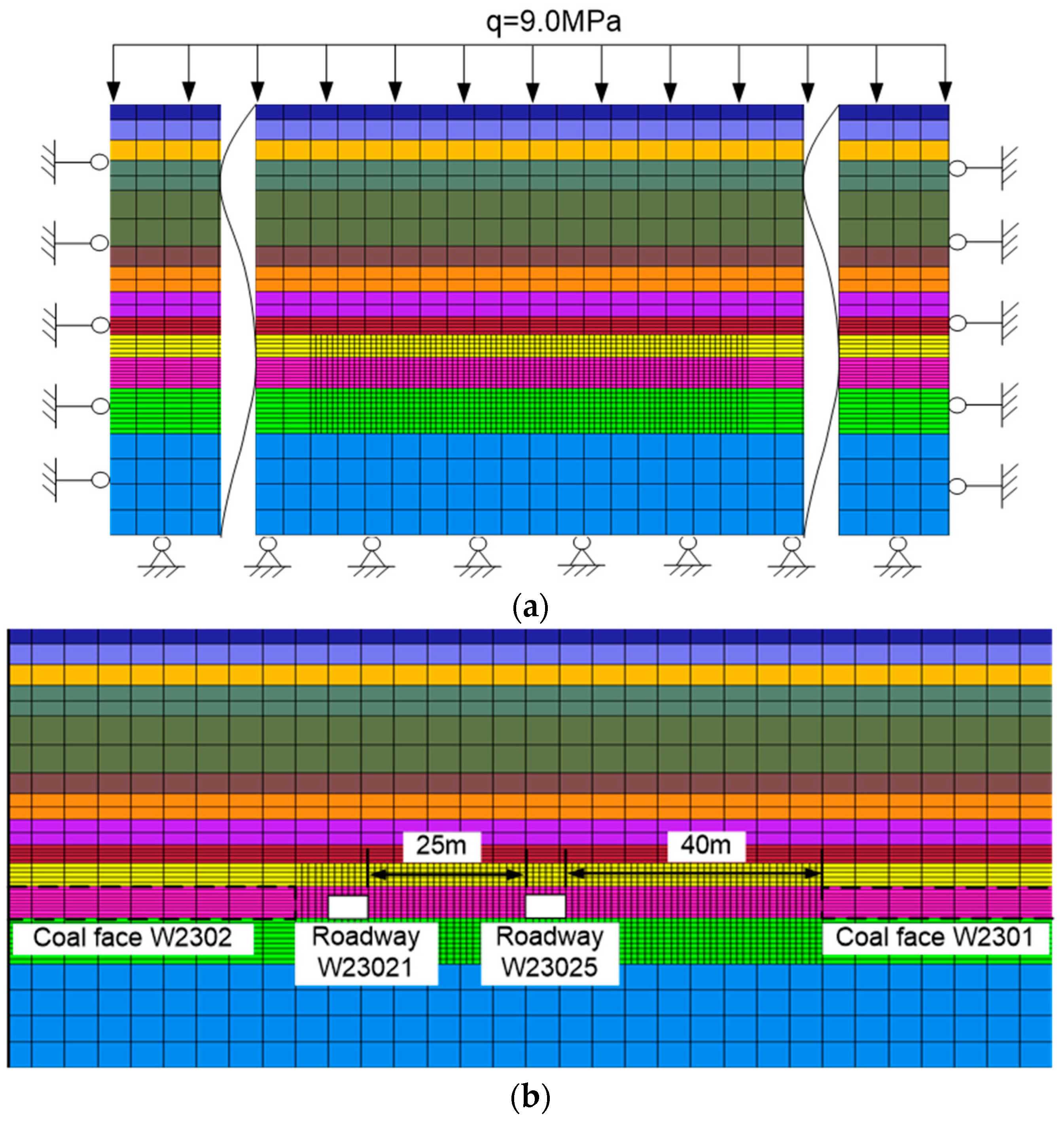
3.2.1. Numerical Model

The model was established based on the actual geological condition. The model had a size of 500 m × 715 m × 97 m (length × width × height) as shown in Figure 7. The thickness of the coal seam is 5.9 m. The coal seam inclination was not considered in the model because the average dip angle is only 4°. The left and right boundaries of the model were horizontally velocity-constrained, as well as the front and rear boundaries. The bottom boundary was vertically fixed. The upper boundary was arranged vertically, which was equivalent to the weights of the overlying strata with 360 m thickness. The in situ stresses were applied in the form of initial stress, and the side pressure coefficient was 1.5. The width of coalface W 2301 and W 2302 were both 220 m. The width of the pillar between roadway W 23025 and coalface W 2301 was 40 m. The width of the pillar between roadway W 23025 and W 23021 was 25 m. The sections of roadways were all 5.0 m in width and 3.8 m in height. It should be noted that the forced mechanism of the reused roadway was mainly analyzed via the numerical simulation. Hence, the U-shape and rock bolt and cable supports were not modeled. Besides, the variable geometry of the excavation was not taken into account in the spatial model to take that as an ideal case.

3.2.2. Constitutive Model and Model Parameters

The Mohr-Coulomb criterion [38] was used as the failure criterion for simulation in initial equilibrium calculation [39]. The mechanical parameters of rocks were determined by field sampling and laboratory testing as listed in Table 1, and the strain–soften model [40] was used in a floor, roof and coal seam during mining operation.

3.2.3. Roadway Deformation Simulation Results

In order to analyze the influence of two mining operations, the roadway deformation due to initial gravitational settling was firstly recorded and then the additional deformations due to coalface advancing were calculated step by step. The coalface advanced 10 m every time. The deformation curves are shown in Figure 8 and compared with the field monitoring results.
It can be found from Figure 8 that the deformation value and range of roadway W 23021 agree with the field monitoring results both during the first mining (coalface W 2301) and during the second mining (coalface W 2302). The roadway deformation during the first mining (coalface W 2301) can also be divided into three stages: initial deformation, violent deformation and plateaued deformation. The roadway deformation during the second mining (coalface W 2302) can also be divided into three stages: initial deformation, slow deformation and violent deformation. The numerical simulation results can demonstrate the monitoring results well, and hence the numerical model is convincible.

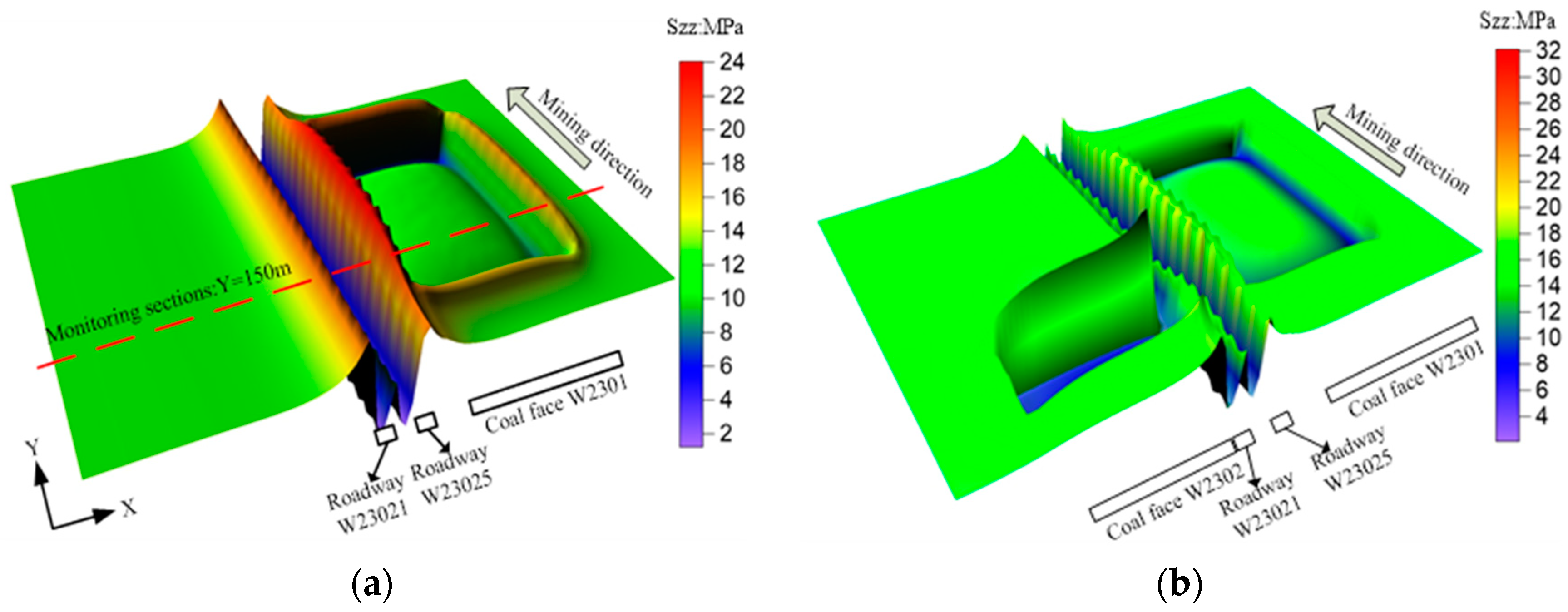
3.2.4. Stress Distribution Simulation Results

The reused roadway suffered two mining operations, so the analysis should be in a dynamic view [41]. According to the field monitoring and mine pressure theory, roadway W 23021 was reserved on the side of goaf and suffered the lateral abutment pressure during the first mining (coalface W 2301). During the second mining, roadway W 23021 became deformed ahead of coalface W 2302 and was abandoned up to behind it, so the roadway W 23021 suffered the leading abutment pressure. The 3D contours of the vertical stress of the coal seam are shown in Figure 9, and the vertical stress contours of monitoring section during the two mining operations are shown in Figure 10 and Figure 11.
Figure 9a indicates that the vertical stress of the coal seam was concentrated on the side of the coalface, forming the lateral abutment pressure during the first mining operation(coalface W 2301). The range of the lateral abutment pressure covered the reused roadway W 23021 and W 23025. The pillar between the two roadways has yielded plastic deformation and the stress was reduced. The stress in the area outside the roadways was increased obviously. Figure 9b shows that the vertical stress of the coal seam was increased in front of coalface W 2302 during the second mining, which is called the leading abutment pressure. The stress state in the area outside the roadway W 23021 was influenced obviously by this leading abutment pressure.
The phenomena of stress concentration on two sides of roadways can be seen from Figure 10, and the vertical stress is increased with the advancing of the coalface, which reflects the influence of lateral abutment pressure of coalface W 2301. When the monitoring section is 50 m ahead of coalface W 2301, the maximum value of concentrated stress on the right side of roadway W 23025 is about 18 MPa (Figure 10a). With the advancement of the coalface, the concentrated stress is increased to about 22 MPa and its range is also rapidly enlarged until the monitoring section is 150 m behind of coalface W 2301, which corresponds to the violent deformation stage (Figure 10e). Then, the concentrated stress and its range are increased slowly. After the monitoring section was placed 200 m behind coalface W 2301, the concentrated stress and its range became stable and no longer changed obviously, which corresponds to the plateaued deformation stage. Hence, a permanent deformation is achieved at this moment.
Figure 11 shows that the concentrated stress and its range are increased further because of the second mining of coalface W 2302. It was noticed that the concentrated stress and its range are gradually increased with the advancing of coalface W 2302. When the monitoring section is 100 m ahead of coalface, the maximum value of concentrated stress on the left side of roadway W 23021 is 18 MPa. Then it increased rapidly to 28 MPa with the coalface advancing. The concentrated stress on the right side of roadway W 23021 is almost identical. Hence, the roadway deformation became more serious in front of coalface W 2302.
The numerical simulation revealed that the reused roadway was significantly affected by the lateral abutment pressure during the first mining, and it was significantly affected by the leading abutment pressure during the second mining. The evolution of the stress state is consistent with the deformation monitored above, and therefore such a forced mechanism is the cause of deformation and damage of the reused roadway. Therefore, the lateral abutment pressure and the leading abutment pressure are the main causes of the deformation of reused roadway.

4. Grouting Control Technology

Based on the above, grouting control technology is discussed in this section. The flow and strength properties of self-developed inorganic double-fluid grouting material were introduced. The reasonable grouting opportunities were confirmed according to the deformation characteristics of the reused roadway. The drilling arrangement and grouting technological parameters were determined comprehensively, and the engineering application was conducted to validate the grouting control effect.

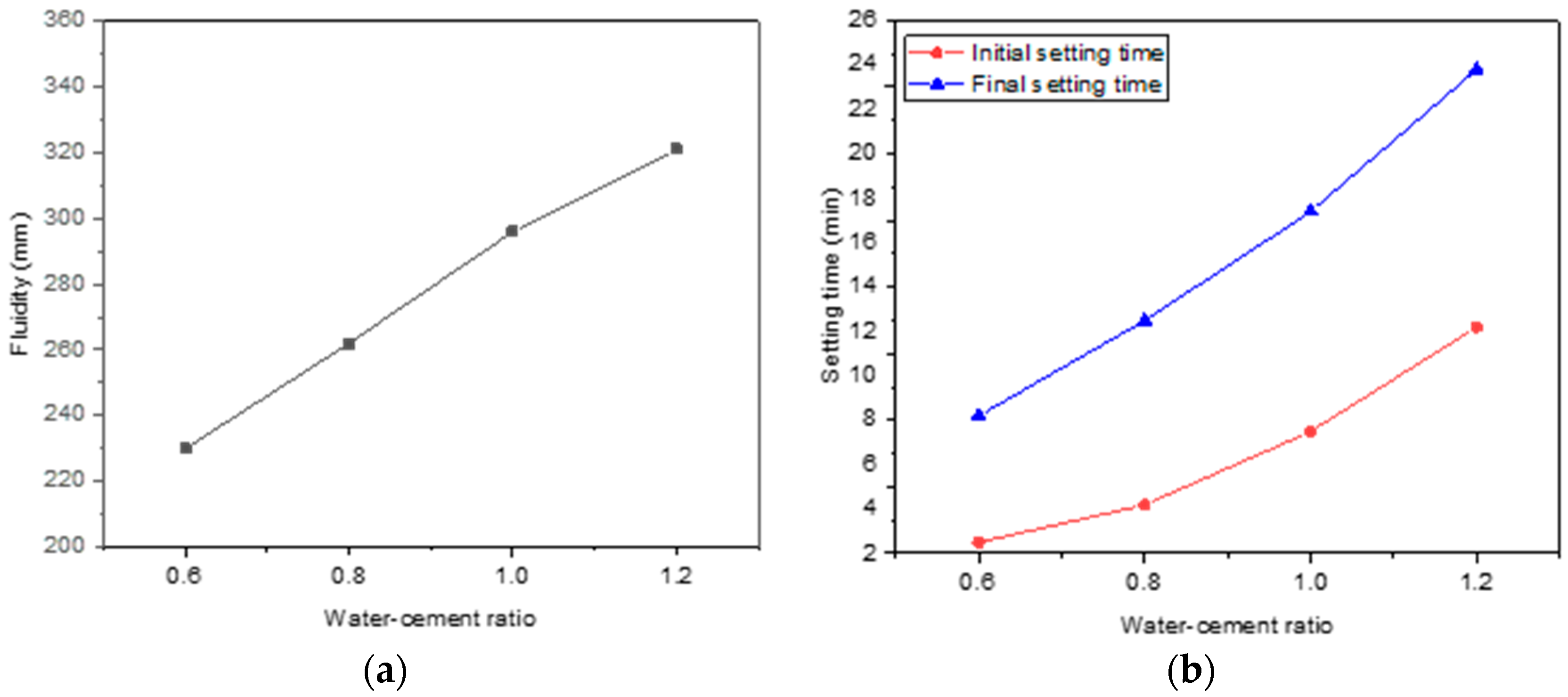
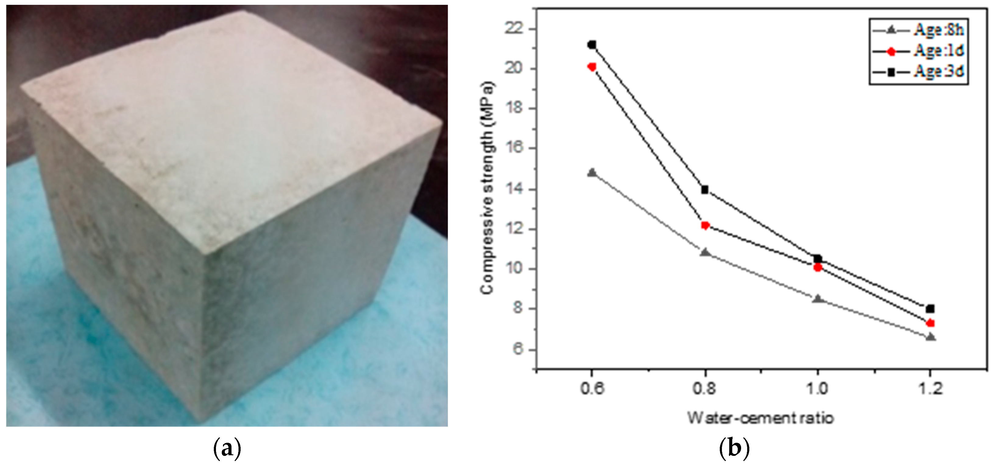
4.1. Grouting Material

Although grouting technology has been applied in coal mines widely, proper grouting materials remain to be further developed. Traditional cement has thick particles and poor injectability. Polymer chemical materials are toxic and easy to ignite, and they are expensive [30,42]. The properties of perfect grouting materials must meet the requirements of fast mining speed, high mining intensity and inevitable time effects that are the main characteristics of a fully mechanized coalface with large mining height. In addition to high strength, fine flowability is also needed for grouting materials so as to ensure that they can easily reach the failure zone of roadway-surrounding rock. Meanwhile, the initial and final setting time must be satisfied with the rapid development of a plastic failure zone of roadway-surrounding rock. A new inorganic double-fluid grouting material has been self-developed [43,44]. The flow and setting characteristics of slurry with different water–cement ratios are shown in Figure 12. The compressive strength curves of slurry consolidation with different water–cement ratios are shown in Figure 13.
As shown in Figure 12, the initial and final setting time of slurry is increased with the increasing water–cement ratio. The setting time of slurry was very short when the water–cement ratio was 0.6, in which the slurry cannot have enough time to flow into the failure zone. Once the water–cement ratio is increased to 0.8, the initial setting time of slurry is more than 4.5 min and final setting time more than 12 min, which can satisfy the requirement of slurry flowability.
As shown in Figure 13, the compressive strength of slurry consolidation is decreased with the increasing of water–cement ratio. The compressive strength of slurry consolidation is more than 10 MPa until the water–cement ratio is decreased to 1.0.
By combining the analysis of flowability and strength characteristics, it can be determined that the water–cement ratio ought to be 0.8~1.0 in order to satisfy the the engineering performance requirements.

4.2. Grouting Opportunity

A reasonable grouting opportunity is crucial for grouting engineering. The reused roadway suffered twice from the dynamic pressure of coalface mining. When the roadway has not been affected by the dynamic pressure of coalface, the surrounding rock of the roadway is relatively stable and its permeability is poor, and thus the slurry is difficult to be injected into the surrounding rock. After the roadway suffers from the dynamic pressure of coalface, some cracks are produced in the surrounding rock and develop gradually, which provides the possibility for large-area grouting [45,46]. Therefore, the grouting opportunities should be determined according to the evolution of the dynamic pressure of coalface and the deformation characteristics of the reused roadway.
As mentioned in the previous section, the reused roadway was significantly affected by the lateral pressure during the first mining, and by the leading abutment pressure during the second mining. The lagging stable deformation characteristics are significant during the first mining. The roadway deformation range is obvious from 80 m ahead of the coalface to 320 m behind of the coalface and can be divided into three stages: initial deformation, violent deformation and plateaued deformation. During the second mining, the roadway deformation range starts from 110 m ahead of the coalface and can be divided into three stages: initial deformation, slow deformation and violent deformation. The reasonable opportunities can be determined by the roadway deformation curves during two mining operations as shown in Figure 14.
The first grouting opportunity was suggested to be in the front part of the plateaued deformation stage during the first mining operation (coalface W 2301), which is determined as 200~250 m behind of the coalface. The roadway lagging stable deformation has become stable basically and damage cracks kept almost unchanged at this stage. Therefore, the grouting materials can be injected well and fully consolidated so as to improve the bearing capability of roadway-surrounding rock that will sustain the second mining influence.
The second grouting opportunity was suggested to be in the slow deformation stage during the second mining operation (coalface W 2302), which is determined to be 25~55 m ahead of the coalface. The deformation of the roadway is gradually increased at this stage. So, damage cracks are produced, which provide the possibility for large-area grouting. The grouting at this stage can strengthen the broken surrounding rock of the roadway so as to improve the overall stability of the roadway, which is helpful to withstand the influence of the leading abutment pressure of the coalface at next stage.

4.3. Grouting Drilling Arrangement and Technological Parameters

The damaged depth of surrounding rock in roadway W 23021 is about 10 m based on previous experience. This point of view can be verified by the results of borehole peeping results: cracks developed fully within 5 m surrounding the roadway, and then decreased with the distance away from the roadway surface; they were rarely observed at distances further than about 10 m. Hence, the depth of the grouting holes should be about 10 m. In this section, grouting drilling was carried out by combining deep and shallow holes for the comprehensive consideration of the depth and breadth of grouting. The drilling layout is shown in Figure 15.
Shallow holes were adopted for upper drilling and deep holes were adopted for lower drilling. The depths of the shallow and deep holes were 8 m and 12 m, respectively. The drilling diameters were both 42 mm, and the elevation angles of shallow and deep holes were 20° and 10°, respectively. The distance h1 (from opening position of shallow holes to the roadway roof) was 0.6~1.0 m, and the distance h2 (from opening position of deep holes to the roadway floor) was 1.5~2.0 m. The distance between two adjacent holes in each row was 6 m.
The grouting system was composed of two pneumatic mixing barrels, QB 150, two slurry-holding barrels, a pneumatic double liquid grouting pump 2ZBQ50/19, and corresponding pipelines and mixers. The water–cement ratio ought to be set within 0.8~1.0 as explained above. If the slurry leakage was serious, the water–cement ratio could also be reduced to 0.7. The grouting pressure was generally set at 6~8 MPa and could be reduced to 4~6 MPa if the slurry leakage was serious in the fractured zones.

4.4. Application Effect

To evaluate the effect of engineering application, borehole peeping and roadway deformation monitoring after grouting were conducted [47,48]. The results are shown in Figure 16 and Figure 17.
Figure 16 shows that the overall integrity of the surrounding rock was improved after grouting. The fractures and voids were filled by the slurry and hence the surrounding coal rock mass became intact. The damaged coal rock has been effectively bonded and consolidated due to grouting. As shown from the curves in Figure 17, both the roadway deformation value and its range were decreased obviously than those before grouting. The maximum value of the two sides’ convergency was about 750 mm before grouting, while it was about 560 mm after grouting, which totals a reduction of about 12.0%. The maximum value of the floor-to-roof convergency was about 550 mm before grouting, while it was about 400 mm after grouting, which totals a reduction of about 27.3%.
It can be concluded from the comparative analysis that the grouting operation has greatly improved the broken surrounding rock of the reused roadway and reduced its deformation dramatically.

4.5. Future Work

As mentioned above, the grouting technology played a better role in roadway-surrounding rock. However, the underground environment is complex and changeable, and the grouting is a hidden project. Hence, there is a series of work to be implemented and improved in the future.
(1) The grouting is a kind of concealed project, so the testing of the grouting effect is different. In this paper, the methods of borehole peeping and roadway deformation monitoring were used. In the future work, other means of monitoring should be adopted to investigate the grouting control effect accurately and conveniently.
(2) For underground roadways, bolt(cable) support is still the necessary method to control roadway deformation, although the grouting reinforcement could improve the integral stability and bearing capacity of surrounding rock effectively. The rational roadway repair and reinforcement should be investigated deeply and adopted in some serious damaged areas so as to take better effect by combining grouting and bolt(cable) supports.

5. Conclusions

The study was conducted based on a reused roadway in a fully mechanized coalface with large mining height, which located in Sihe coal mine. The roadway deformation characteristics and forced mechanism were analyzed by field monitoring and numerical simulation, and then the reasonable grouting opportunities and technological parameters were correspondingly determined and validated by using self-developed inorganic double-fluid grouting material. The conclusions are summarized as follows:
  • The roadway deformation was significantly affected by the lateral abutment pressure of the coalface during the first mining operation, which is characterized by lagging stable deformation and means a permanent deformation is achieved only after the coalface has advanced and passed a long distance. The deformation range during the first mining can be divided into initial deformation, violent deformation and plateaued deformation stages.
  • The roadway deformation is significantly affected by the leading abutment pressure of the coalface during the second mining operation, which is characterized by ceaselessly increasing deformation and means that the deformation becomes more and more severe with the advancing of the coalface. The deformation range during the second mining can be divided into initial deformation, slow deformation and violent deformation stages.
  • The grouting operation of the reused roadway ought to be conducted twice. The first grouting opportunity was suggested to be in the front part of the plateaued deformation stage during the first mining operation because the roadway damage had become stable basically at this stage. The second grouting opportunity was suggested in the slow deformation stage during the second mining operation because the gradually developed damage cracks provide the possibility for large-area grouting.
  • The grouting operation has greatly improved the broken surrounding rock of the reused roadway and reduced its deformation dramatically. However, the grouting is difficult to be conducted in several seriously damaged areas, in which the chemical materials could be used to form a surface-integrity layer that can seal the surface crack channels quickly. Some additional roadway repairs and reinforcements such as bolt or cable supports and so on are still be necessary for parts of severely damaged roads.

Author Contributions

L.Z.: Formal analysis, Methodology, Writing—original draft; Z.C.: Supervision, Writing—review & editing; R.P.: Supervision, Writing—review & editing; T.W.: Software; L.W.: Data curation; D.L.: Data curation. All authors have read and agreed to the published version of the manuscript.

Funding

This work was supported by the Second Tibetan Plateau Scientific Expedition and Research Program (STEP) (Grant No. 2019QZKK0904), the National Natural Science Foundation of China (Grant No. 41972296) and the Fundamental Research Funds for the Central Universities (Grant No. 2022YJSMT05).

Acknowledgments

The authors wish to gratefully acknowledge the mine management and co-workers in Sihe coal mine of Jincheng Coal mining group for their help during the field studies. Special thanks should be expressed to Zuqiang Xiong in Henan polytechnic university. The authors would like to thank the editors and the anonymous reviewers who presented critical and constructive comments for the improvement of this paper.

Conflicts of Interest

The authors declare that they have no competing interest.

References

  1. Kang, Y.; Liu, Q.; Xi, H. Numerical analysis of THM coupling of a deeply buried roadway passing through composite strata and dense faults in a coal mine. Bull. Eng. Geol. Environ. 2014, 73, 77–86. [Google Scholar] [CrossRef]
  2. Singh, R.; Singh, T. Investigation into the Behaviour of a Support System and Roof Strata during Sublevel Caving of a Thick Coal Seam. Geotech. Geol. Eng. 1999, 17, 21–35. [Google Scholar] [CrossRef]
  3. Unver, B.; Yasitli, N. Modelling of strata movement with a special reference to caving mechanism in thick seam coal mining. Int. J. Coal Geol. 2006, 66, 227–252. [Google Scholar] [CrossRef]
  4. Ju, J.; Xu, J. Structural characteristics of key strata and strata behaviour of a fully mechanized longwall face with 7.0 m height chocks. Int. J. Rock Mech. Min. Sci. 2013, 58, 46–54. [Google Scholar] [CrossRef]
  5. Kong, D.-Z.; Cheng, Z.-B.; Zheng, S.-S. Study on the failure mechanism and stability control measures in a large-cutting-height coal mining face with a deep-buried seam. Bull. Eng. Geol. Environ. 2019, 78, 6143–6157. [Google Scholar] [CrossRef]
  6. Huang, Q.; He, Y.; Li, F. Research on the Roof Advanced Breaking Position and Influences of Large Mining Height Working Face in Shallow Coal Seam. Energies 2020, 13, 1685. [Google Scholar] [CrossRef]
  7. Yuan, Y.; Tu, S.H.; Zhang, X.G.; Li, B. Dynamic effect and control of key strata break of immediate roof in fully mechanized mining with large mining height. Shock Vib. 2015, 2015, 657818. [Google Scholar]
  8. Li, C.; Zuo, J.; Wei, C.; Xu, X.; Zhou, Z.; Li, Y.; Zhang, Y. Fracture Development at Laminated Floor Layers under Longwall Face in Deep Coal Mining. Nat. Resour. Res. 2020, 29, 3857–3871. [Google Scholar] [CrossRef]
  9. Chen, J.; Wu, H.; Zhang, X.; Gao, X.; Ling, T.; Zhang, Z. Experimental Study of the Plastic Zone and Stress Asymmetric Distribution in Roadway Layered Surrounding Rocks. Appl. Sci. 2022, 12, 6108. [Google Scholar] [CrossRef]
  10. Li, G.; Ma, F.; Guo, J.; Zhao, H. Deformation Characteristics and Control Method of Kilometer-Depth Roadways in a Nickel Mine: A Case Study. Appl. Sci. 2020, 10, 3937. [Google Scholar] [CrossRef]
  11. Islam, M.R.; Shinjo, R. Numerical simulation of stress distributions and displacements around an entry roadway with igneous intrusion and potential sources of seam gas emission of the Barapukuria coal mine, NW Bangladesh. Int. J. Coal Geol. 2009, 78, 249–262. [Google Scholar] [CrossRef]
  12. Liu, X.; Yang, S.; Ding, X.; Zhang, C.; Wang, X.; Zhou, B.; Ding, X. Physical Simulation and Monitoring the Deformation and Fracture of Roadway in Coal Mining. Adv. Civ. Eng. 2018, 2018, 2607957. [Google Scholar] [CrossRef]
  13. Mandal, P.K.; Das, A.J.; Kumar, N.; Bhattacharjee, R.; Tewari, S.; Kushwaha, A. Assessment of roof convergence during driving roadways in underground coal mines by continuous miner. Int. J. Rock Mech. Min. Sci. 2018, 108, 169–178. [Google Scholar] [CrossRef]
  14. Wang, H.; Xue, S.; Jiang, Y.; Deng, D.; Shi, S.; Zhang, D. Field Investigation of a Roof Fall Accident and Large Roadway Deformation under Geologically Complex Conditions in an Underground Coal Mine. Rock Mech. Rock Eng. 2018, 51, 1863–1883. [Google Scholar] [CrossRef]
  15. Zang, C.; Chen, M.; Zhang, G.; Wang, K.; Gu, D. Research on the failure process and stability control technology in a deep roadway: Numerical simulation and field test. Energy Sci. Eng. 2020, 8, 2297–2310. [Google Scholar] [CrossRef]
  16. Chen, D.; Ji, C.; Xie, S.; Wang, E.; He, F.; Cheng, Q.; Zhang, Q. Deviatoric Stress Evolution Laws and Control in Surrounding Rock of Soft Coal and Soft Roof Roadway under Intense Mining Conditions. Adv. Mater. Sci. Eng. 2020, 2020, 5036092. [Google Scholar] [CrossRef]
  17. Zhang, L.; Shen, W.; Li, X.; Wang, Y.; Qin, Q.; Lu, X.; Xue, T. Abutment Pressure Distribution Law and Support Analysis of Super Large Mining Height Face. Int. J. Environ. Res. Public Health 2023, 20, 227. [Google Scholar] [CrossRef]
  18. Sun, Y.; Bi, R.; Chang, Q.; Taherdangkoo, R.; Zhang, J.; Sun, J.; Huang, J.; Li, G. Stability Analysis of Roadway Groups under Multi-Mining Disturbances. Appl. Sci. 2021, 11, 7953. [Google Scholar] [CrossRef]
  19. Zhang, D.; Zhao, H.; Li, G. Study on Size Optimization of a Protective Coal Pillar under a Double-Key Stratum Structure. Appl. Sci. 2022, 12, 11868. [Google Scholar] [CrossRef]
  20. Basarir, H.; Sun, Y.; Li, G. Gateway stability analysis by global-local modeling approach. Int. J. Rock Mech. Min. 2019, 113, 31–40. [Google Scholar] [CrossRef]
  21. Kang, H.; Wu, L.; Gao, F.; Lv, H.; Li, J. Field study on the load transfer mechanics associated with longwall coal retreat mining. Int. J. Rock Mech. Min. Sci. 2019, 124, 104141. [Google Scholar] [CrossRef]
  22. Yang, X.J.; Yang, G.; Huang, R.F.; Wang, Y.J.; Liu, J.N.; Zhang, J.; Hou, S.L. Comprehensive study on surrounding rock failure characteristics of longwall roadway and control rechniques. Appl. Sci. 2021, 11, 9795. [Google Scholar] [CrossRef]
  23. Wu, X.Y.; Liu, H.T.; Li, J.W.; Guo, X.F.; Lv, K.; Wang, J.Y. Temporal-spatial evolutionary law of plastic zone and stability control in repetitive mining roadway. J. China Coal Soc. 2020, 45, 3389–3400. (In Chinese) [Google Scholar]
  24. Wu, X.Y.; Wang, J.Y.; Chen, S.J.; Zhang, Y.J.; Bu, Q.W. Regulation principle and stability control of plastic zone in repeated mining roadway. Rock Soil Mech. 2022, 43, 205–217. (In Chinese) [Google Scholar]
  25. Gao, Y.; Liu, R.; Jing, H.; Chen, W.; Yin, Q. Hydraulic properties of single fractures grouted by different types of carbon nanomaterial-based cement composites. Bull. Eng. Geol. Environ. 2020, 79, 2411–2421. [Google Scholar] [CrossRef]
  26. Jones, B.R.; Van Rooy, J.L.; Mouton, D.J. Verifying the ground treatment as proposed by the Secondary Permeability Index during dam foundation grouting. Bull. Eng. Geol. Environ. 2019, 78, 1305–1326. [Google Scholar] [CrossRef]
  27. Song, B.; Zhang, S.; Zhang, D.; Fan, G.; Yu, W.; Zhao, Q.; Liang, S. Inorganic Cement Grouting for Reinforcing Triangular Zone of Highly Gassy Coal Face with Large Mining Height. Energies 2018, 11, 2549. [Google Scholar] [CrossRef]
  28. Stromsvik, H.; Gammelsaeter, B. Investigation and assessment of pre-grouted rock mass. B Eng. Geol. Env. 2020, 79, 2543–2560. [Google Scholar] [CrossRef]
  29. Sha, F.; Li, S.; Liu, R.; Li, Z.; Zhang, Q. Experimental study on performance of cement-based grouts admixed with fly ash, bentonite, superplasticizer and water glass. Constr. Build. Mater. 2018, 161, 282–291. [Google Scholar] [CrossRef]
  30. Zhang, J.; Sun, Y. Experimental and Mechanism Study of a Polymer Foaming Grouting Material for Reinforcing Broken Coal Mass. KSCE J. Civ. Eng. 2019, 23, 346–355. [Google Scholar] [CrossRef]
  31. Liu, Y.; Chen, B. Research on the preparation and properties of a novel grouting material based on magnesium phosphate cement. Constr. Build. Mater. 2019, 214, 516–526. [Google Scholar] [CrossRef]
  32. Sun, X.; Wang, L.; Lu, Y.; Jiang, B.; Li, Z.; Zhang, J. A yielding bolt-grouting support design for a soft-rock roadway under high stress: A case study of the Yuandian No. 2 coal mine in China. J. South. Afr. Inst. Min. Met. 2018, 118, 71–82. [Google Scholar] [CrossRef]
  33. Zhang, W.; Li, S.; Wei, J.; Zhang, Q.; Liu, R.; Zhang, X.; Yin, H. Grouting rock fractures with cement and sodium silicate grout. Carbonate Evaporite 2017, 33, 211–222. [Google Scholar] [CrossRef]
  34. Sun, Y.; Li, G.; Zhang, J. Investigation on jet grouting support strategy for controlling time-dependent deformation in the roadway. Energy Sci. Eng. 2020, 8, 2151–2158. [Google Scholar] [CrossRef]
  35. Xie, Z.; Zhang, N.; Feng, X.; Liang, D.; Wei, Q.; Weng, M. Investigation on the evolution and control of surrounding rock fracture under different supporting conditions in deep roadway during excavation period. Int. J. Rock Mech. Min. Sci. 2019, 123, 104122. [Google Scholar] [CrossRef]
  36. Chang, Q.; Yao, X.; Leng, Q.; Cheng, H.; Wu, F.; Zhou, H.; Sun, Y. Strata Movement of the Thick Loose Layer under Strip-Filling Mining Method: A Case Study. Appl. Sci. 2021, 11, 11717. [Google Scholar] [CrossRef]
  37. Skrzypkowski, K.; Zagórski, K.; Zagórska, A.; Apel, D.B.; Wang, J.; Xu, H.; Guo, L. Choice of the Arch Yielding Support for the Preparatory Roadway Located near the Fault. Energies 2022, 15, 3774. [Google Scholar] [CrossRef]
  38. Zhang, H.; Chen, L.; Zhu, Y.; Zhou, Z.; Chen, S. Stress Field Distribution and Deformation Law of Large Deformation Tunnel Excavation in Soft Rock Mass. Appl. Sci. 2019, 9, 865. [Google Scholar] [CrossRef]
  39. Han, Y.; Liu, X.; Li, D.; Tu, Y.; Deng, Z.; Liu, D.; Wu, X. Model test on the bearing behaviors of the tunnel-type anchorage in soft rock with underlying weak interlayers. Bull. Eng. Geol. Environ. 2020, 79, 1023–1040. [Google Scholar] [CrossRef]
  40. Zhou, J.W.; Xu, W.Y.; Li, M.W.; Zhou, X.Q.; Chong, S.H.I. Application of rock strain softening model to numerical analysis of deep tunnel. Chin. J. Rock Mech. Eng. 2009, 28, 1116–1127. (In Chinese) [Google Scholar]
  41. Cheng, Z.; Liu, B.; Zou, Q.; Wang, X.; Feng, J.; Zhao, Z.; Sun, F. Analysis of Spatial–Temporal Evolution of Mining-Induced Fracture Field: A Case Study Using Image Processing in the Shaqu Coal Mine, China. Nat. Resour. Res. 2020, 29, 1601–1615. [Google Scholar] [CrossRef]
  42. Zhang, C.; Yang, J.S.; Fu, J.Y.; Ou, X.F.; Xie, Y.P.; Liang, X. Performance evaluation of modified cement-sodium silicate grouting material for pre-reinforcing loose deposit tunnels. J. Mater. Civ. Eng. 2019, 31, 06019003. [Google Scholar] [CrossRef]
  43. Xiong, Z.; Wang, P.; Wang, Y. Hydration Behaviors of Portland Cement with Different Lithologic Stone Powders. Int. J. Concr. Struct. Mater. 2015, 9, 55–60. [Google Scholar] [CrossRef]
  44. Zhang, Y.; Wang, Y.; Li, T.; Xiong, Z.; Sun, Y. Effects of lithium carbonate on performances of sulphoaluminate cement-based dual liquid high water material and its mechanisms. Constr. Build. Mater. 2018, 161, 374–380. [Google Scholar] [CrossRef]
  45. Ju, Y.; Wang, Y.; Su, C.; Zhang, D.; Ren, Z. Numerical analysis of the dynamic evolution of mining-induced stresses and fractures in multilayered rock strata using continuum-based discrete element methods. Int. J. Rock Mech. Min. Sci. 2019, 113, 191–210. [Google Scholar] [CrossRef]
  46. Liu, H.; Deng, K.; Zhu, X.; Jiang, C. Effects of mining speed on the developmental features of mining-induced ground fissures. Bull. Eng. Geol. Environ. 2019, 78, 6297–6309. [Google Scholar] [CrossRef]
  47. Wang, H.; Jiang, Y.; Xue, S.; Shen, B.; Wang, C.; Lv, J.; Yang, T. Assessment of excavation damaged zone around roadways under dynamic pressure induced by an active mining process. Int. J. Rock Mech. Min. Sci. 2015, 77, 265–277. [Google Scholar] [CrossRef]
  48. Yu, W.; Wang, W.; Chen, X.; Du, S. Field investigations of high stress soft surrounding rocks and deformation control. J. Rock Mech. Geotech. 2015, 7, 421–433. [Google Scholar] [CrossRef] [Green Version]
Figure 1. Roadway layout of coalface W 2302.
Applsci 13 01951 g001
Figure 2. Stratigraphic column.
Applsci 13 01951 g002
Figure 3. Support of roadway W 23021.
Applsci 13 01951 g003
Figure 4. Layout of the monitoring station of roadway deformation.
Applsci 13 01951 g004
Figure 5. Deformation curves of roadway W 23021 during the first mining.
Applsci 13 01951 g005
Figure 6. Deformation curves of roadway W 23021 during the second mining.
Applsci 13 01951 g006
Figure 7. Schematic diagram of numerical model. (a) Numerical model and boundary conditions; (b) Schematic diagram of coalface and roadway layout.
Applsci 13 01951 g007
Figure 8. Deformation curves of numerical simulation and field monitoring. (a) During the first mining (coalface W2301); (b) During the second mining (coalface W2302).
Applsci 13 01951 g008aApplsci 13 01951 g008b
Figure 9. 3D contours of vertical stress in coal seam. (a) First mining (coalface W 2301 advanced 350 m); (b) Second mining (coalface W 2302 advanced 100 m).
Applsci 13 01951 g009
Figure 10. Vertical stress contours of monitoring section during the first mining. (a) 50 m ahead of coalface W 2301; (b) 0.5 m behind coalface W 2301; (c) 50 m behind coalface W 2301; (d) 100 m behind coalface W 2301; (e) 150 m behind coalface W 2301; (f) 200 m behind coalface W 2301.
Applsci 13 01951 g010
Figure 11. Vertical stress contours of monitored section during the second mining. (a) 100 m ahead of coalface W 2302; (b) 70 m ahead of coalface W 2302; (c) 40 m ahead of coalface W 2302; (d) 10 m ahead of coalface W 2302.
Applsci 13 01951 g011
Figure 12. Flow and setting curves of slurry with different water–cement ratios. (a) Fluidity curve; (b) Setting time curves.
Applsci 13 01951 g012
Figure 13. Compressive strength curves of slurry consolidation with different water–cement ratios. (a) Slurry consolidation sample; (b) Compressive strength curves.
Applsci 13 01951 g013
Figure 14. Schematic diagram of grouting opportunities in reused roadway.
Applsci 13 01951 g014
Figure 15. Grouting hole layout of roadway W 23021. (a) The plan of the opening position on the roadway side; (b) The cross-section drawn of the borehole arrangement.
Applsci 13 01951 g015
Figure 16. Borehole peeping results after grouting. (a) Depth = 0.71 m; (b) Depth = 1.16 m; (c) Depth = 2.07 m; (d) Depth = 3.58 m; (e) Depth = 5.78 m; (f) Depth = 10.46 m. The one in the red circle is the slurry filling the cracks.
Applsci 13 01951 g016
Figure 17. Roadway deformation curves before and after grouting. (a) Floor-to-roof convergency; (b) Two sides’ convergency; (c) Roof subsidence; (d) Floor heave.
Applsci 13 01951 g017aApplsci 13 01951 g017b
Table 1. Mechanical parameters of rocks in numerical simulation.
LithologyTensile Strength/MPaElastic Modulus/GPaCohesion/MPaInternal Friction Angle/ºPoisson’s RatioDensity/kg/m3
Mudstone1.13.953.0280.242500
Sandy mudstone0.95.194.0300.302500
Fine-grained sandstone2.678.266.0320.292500
Medium-grained sandstone1.76.313.6320.262500
Coal0.563.662.5260.221400
Disclaimer/Publisher’s Note: The statements, opinions and data contained in all publications are solely those of the individual author(s) and contributor(s) and not of MDPI and/or the editor(s). MDPI and/or the editor(s) disclaim responsibility for any injury to people or property resulting from any ideas, methods, instructions or products referred to in the content.

