Abstract
This paper aims to provide essential guidance for the crashworthiness design of cutting energy-absorbing structures for subway vehicles. By investigating tool failure with experiment and numerical approaches, a new energy-absorbing tube structure was proposed and optimized to improve the crashworthiness and reliability of the cutting energy-absorption structure. The impact test results revealed that multiple failure modes occurred in the tool. Mechanical wear occurs mainly in the middle of the cutting edge, while the tool’s tip failure is primarily due to thermal wear. Impact forces were no longer stable due to tool failure. The simulation results of the established tool-tube thermal–structural coupling finite element model were consistent with the tests. The temperature distribution indirectly validated the failure modes in different tool areas. By eliminating the tearing-type fracture mode, the proposed new structure effectively reduced the high temperature of the tool’s tip, better maintained the uniform temperature of the cutting edge, and smoothed changing of the cutting force. Finally, the Kriging surrogate model and NSGA-II algorithm were utilized to obtain the tool’s minimum steady-state temperature (STT) and maximum mean average cutting force (MCF). The optimal solution determined by the minimum distance method is STT = 514 K, MCF = 131 kN.
1. Introduction
Safety is the eternal theme of transportation. Collisions account for 56% of global railroad accidents, causing enormous casualties and property damage [1]. Thin-walled structures, as a general type of energy-absorbing structures, have been widely used in the design of crashworthiness of rail vehicles. The deformation modes of thin-walled tubes mainly include axial folding [2], expansion [3], shrinkage [4], splitting [5], and cutting [6] of the tube body. As a new type of thin-walled energy-absorption structure, cutting energy-absorption structure absorbs collision energy through the integrated process of friction, plastic deformation, and tearing between metal materials [7]. Thus, it has a superior mode for dissipating energy. However, in the process of cutting energy absorption, the tool is subject to intense friction and extrusion of the material being cut. Therefore, the tool is under high temperatures and gradually wears and breaks, that is, it fails. Tool failure will seriously affect its cutting performance, resulting in the impact force of the energy-absorbing structure no longer being stable in the collision process. In severe cases, the safety of the occupants’ lives and property will no longer be guaranteed.
Many scholars have conducted extensive experimental studies on the failure mechanism of tools. The causes and extent of tool failure are various from tool materials, workpiece materials, and cutting conditions. Since cutting temperature has a decisive impact on tool wear, the different wear mechanisms can be divided into two categories according to their sensitivity to cutting temperature: thermal wear and mechanical wear. Thermal wear mainly includes chemical wear (diffusion and oxidation wear), transformation wear, and thermoelectric wear, while mechanical wear mainly includes abrasive wear, adhesion wear, and fatigue wear ([8,9]). According to the form of breakage, tool breakage is divided into brittle and plastic. In the cutting process, carbide, ceramics, and many other high-hardness tools often have brittle breakage occur, such as chipping, shattering, spalling, and cracking when subjected to mechanical and thermal impact ([10,11,12]). High-toughness tools such as high-speed steel (HSS) primarily suffer from plastic breakages, such as burned edges, rolled edges, and fracture [13]. The tools for cutting energy-absorbing structures are often used only once, which means normal wear can be disregarded. However, severe wear and breakage can seriously affect the smoothness of cutting forces and should avoid tool failure during the cutting energy absorption process.
The cutting process is a dynamic physical process with strong thermal–structural coupling. Quantitatively studying the cutting mechanism by the traditional analytical method is challenging, so the finite element method has been widely applied to studying the cutting process. In the field of machining, many scholars primarily focus on cutting forces, cutting heat, chip formation mechanism, and machining surface quality ([14,15,16]). Unlike the former, research on cutting energy-absorbing structures does not focus on machined surface quality. It is more concerned with impact force, energy absorption, and other indicators of crashworthiness. Xia [17] studied the effect of tool parameters on cutting force and energy absorption using coupled thermal–structural simulation. Liu et al. [18] further investigated that the thermal dissipation energy accounted for about 21% of the cutting energy absorption process through coupled thermal–structural simulation. Furthermore, the impact speed, cutting section parameters, and tool parameters had different influences on laws on cutting force and thermal dissipation energy proportion. Yue [19] designed a new dual-knife broaching type anti-climbing energy-absorption structure and studied the significance analysis of the effect of different structural parameters on the energy absorption performance to guide the design of its structural parameters using numerical simulation. Gao et al. [20] proposed a new type of active–passive integrated cutting energy-absorbing structure, which can effectively improve the deformation stroke of the energy-absorbing tube. The effect of different cutting depths and energy-absorbing tube materials on their performance is also investigated under quasi-static tests. Guan et al. [21] divided the chip deformation mode in the cutting energy absorption process into three fracture modes and applied different failure models in cutting and non-cutting areas for numerical simulation. Guo [22] proposes changing the tool of the cutting-type energy-absorbing structure to a metal ball to reduce its stress concentration. However, the poor cutting properties of the metal ball lead to easy damage to the support tool in the area of contact with the ball.
Structural parameter optimization is the primary technical tool to improve the crashworthiness of energy-absorbing structures. As in most real-life engineering applications, crashworthiness optimization can usually be characterized by many design criteria [23]. These design objectives often conflict with each other, so multi-objective optimization methods are widely used in crashworthiness optimization [24]. Energy absorption, average impact force, and peak force are used primarily as optimization objectives of cutting-type energy-absorbing structures. Xia [17] used orthogonal polynomial regression analysis and a genetic algorithm to optimize the cutting force per unit area and the energy absorption per unit volume. Guan et al. [21] performed a multi-objective optimization based on the response surface method and non-dominated sorting genetic algorithm II (NSGA-II) to maximize the energy absorption and minimize the peak force of the energy-absorbing structure under quasi-static loading. Wang et al. [25] compared the accuracy of the polynomial response surface method (RSM) and radial basis function (RBF) surrogate model. Then, the model with fewer errors was applied to optimize the energy absorption and minimize the peak force by the multi-objective particle swarm optimization (MOPSO) algorithm. Peng et al. [26] propose a hybrid optimization approach that combines the theories of multi-objective optimization and multiple-criteria decision making with the consideration of engineering practitioners’ preferences, which can be effectively employed to optimize cutting types’ energy-absorbing structures. In optimization for machining process conditions, many studies have set various optimization objectives to obtain optimal cutting conditions, including tool temperature, wear, breakage, roughness, etc. ([27,28,29]).
However, most research on the existing cutting energy-absorbing structure crashworthiness pays less attention to the tool failure in the energy-absorbing cutting process. Take the subway collision speed (6.94 m/s) specified in the EN15227 standard [30] as an example. It is several times higher than the cutting speed of the normal turning process (about 1 m/s). Therefore, the cutting energy-absorption process can be considered a high-speed cutting process at a large feed, which means the effect of cutting temperature and thermal stress on tool wear and breakage becomes more significant than low-speed cutting [11]. It is essential to study the tool failure in the energy-absorption process to improve the reliability and crashworthiness of the cutting energy-absorption structure.
This paper investigates the tool failure mode of the energy-absorbing cutting structure under axial impact using experimental and numerical methods, and then its reliability and crashworthiness are optimized. Axial impact tests are implemented to obtain the collision response, including force–displacement curves, chip deformation patterns, and tool failure forms. A tool-tube finite element model is developed for coupled thermal–structural analysis, and each collision response is verified by comparing it with experimental results. Finally, a new structure is proposed to reduce the temperature of the tip of the tool and carry out multi-objective optimization of the impact resistance and reliability of the new structure.
2. Impact Test and Results
2.1. Crash Test Setup
In this study, the dynamic impact test of the full-size cutting-type energy-absorbing structure was carried out, and the test conditions were set up in such a way that the test trolley equipped with the cutting anti-climbing energy-absorbing structure at the front end was counterweighted to 13.6 t and then crashed into the rigid wall located on the other side of the rail track with an initial speed of 5 m/s. Figure 1a shows the test layout schematic, including the full-size cutting energy-absorbing structure, test trolley, track, rigid wall, and data acquisition system. The energy-absorbing structure (Figure 1b) is comprised of a support tool, energy absorption tube, an anti-climb device, and six tools. It was bolted to the front of the trolley (Figure 1c), and four dynamic high-frequency force cells (Figure 1d) were fixed to the rigid wall. The energy-absorbing structure and the force cells were attached with trigger tapes in front for zero-point calibration of the data obtained from the data acquisition equipment. Laser-type speed sensors and high-speed cameras were arranged next to the test track to record the test trolley’s initial crash speed and the specimen’s structural deformation during the test.
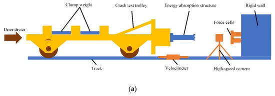
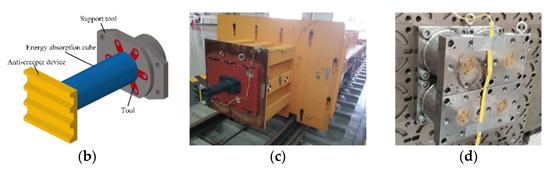
Figure 1.
(a) Layout schematic, (b) cutting-type energy-absorbing structure, (c) test trolley, and (d) force cells.
2.2. Experimental Results and Discussion
2.2.1. Tool Failure Mode
Figure 2 below presents the tool failure mode after the test, which mainly includes noticeable wear of the rake and flank face, deformation, and breakage in the tip area. An indented groove appears on the tool flank face. This formation of grooves on the friction surface parallel to the direction of relative motion is called abrasive wear, a common form of wear on HSS tools. The unevenness on the tool’s rake face is typical adhesion wear. Due to the alternating stress, thermal stress, and structural defects of the tool’s face layer, the material particles on the tool’s face are gradually stuck away by chips or workpieces, which causes adhesion wear of the tool. There are multiple collapses and deformations near the tip of the tool. In the cutting process, the tip and cutting edge will undergo plastic deformation and collapse due to the action of high temperature and high pressure, called transformation wear. It is the main wear form of HSS tools when the cutting temperature exceeds 873 K. There is severe breakage at the tool’s tip. This form of brittle breakage rarely occurs in HSS and other tools with strong toughness. When they face uneven cutting temperatures and shock, if the tool is not sufficiently resistant to thermal cracking impact, excessive thermal stress can form cracks and brittle breakage. Deep grooves, a typical feature of boundary wear, appear near the tip at the junction of the tool’s main and secondary flank faces. The air is not easily accessible in the tool-chip close contact area, and the oxygen supply is sufficient at the edge of this contact area. The tool material reacts with the oxygen in the air to form low-hardness oxides on the surface once the cutting process is at a high temperature. They are easily wiped off by chips or workpieces and form grooves, called oxidation wear, which can seriously lead to the loss of the cutting ability of the tool [13].
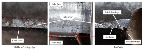
Figure 2.
Tool failure mode.
Therefore, mechanical wear, including abrasive and adhesion wear, causes the cutting edge’s rake and flank face wear. The area in and around the tool’s tip is dominated by thermal wear, such as transformation wear and oxidation wear. The most severe deformation and breakage of the tool are near the tip, indicating that thermal wear effects have a more significant impact on the tool than mechanical wear. Therefore, thermal wear is the primary tool failure mode in this cutting energy-absorption process.
2.2.2. Collision Process Analysis
Tool wear state can be obtained indirectly based on the changing law of impact force, the state of the machined surface of the energy-absorbing tube, and chip deformation mode during the test [31]. Figure 3 illustrates the collision force–displacement curve of the impact test and structural deformation, divided into four stages as follows.
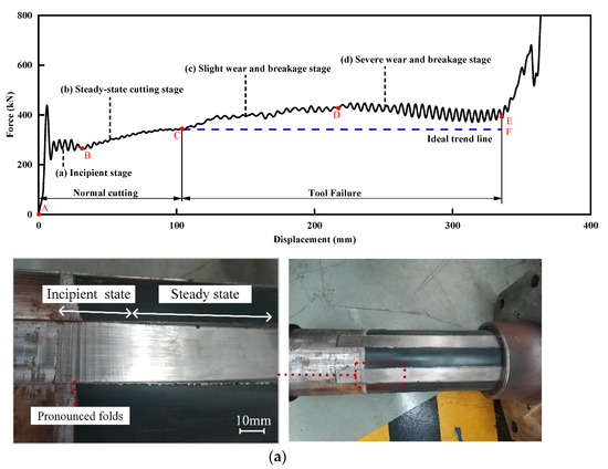
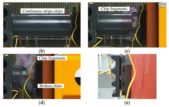
Figure 3.
Force–displacement curves and structural deformation in various stages: (a) incipient stage, (b) steady-state cutting stage, (c) slight wear and breakage stage, (d) severe wear and breakage stage, and (e) after the collision.
The AB segment (0~30 mm) illustrates the incipient stage, from the start of the collision to the entry of steady-state cutting. At the crash moment, the impact force reached an initial peak of 437 kN. In the subsequent 30 mm displacement, the force decreased to 280 kN and maintained oscillation. The unstabilized cutting process resulted in pronounced folds on the machined surface, as seen in Figure 3a.
The BC segment (30~102 mm) illustrates the steady-state cutting stage. During this period, the cutting state becomes stable, and the continuous stripe chips flow out along the tool rake face to curl, as seen in Figure 3b. The accumulated curled chips obstruct the tool movement, and the force continues to increase. After the chip curls to a certain extent, the force no longer significantly increases and stabilizes at 340 kN.
The CD segment (102~220 mm) stands at the slight wear and breakage stage. A large number of broken chips are produced, as seen in Figure 3c. Meanwhile, the impact force continues to increase, and the force oscillation amplitude is significantly larger than that of the BC segment. The tool wear is gradually severe at this time and deteriorated cutting performance leads to increased impact force. In contrast, the CF segment presents an ideal trend line (blue dashed line in Figure 3) without tool wear.
The DE segment (220~360 mm) indicates the severe wear and breakage stage. The tool is severely broken and fails to cut normally, generating many fragmental and broken chips and causing violent force oscillation, as seen in Figure 3d. After the curled chips break, the force decreases slightly. Finally, the curled chip is squeezed by the supporter and tool to the back of the anti-climb creeper device, as seen in Figure 3e. The force increases abruptly, and the collision ends.
3. Numerical Simulation and Results
The study in Section 2 shows that thermal wear is the primary tool wear mode in the test. The tool temperature during the impact process is so hard to measure directly. In contrast, numerical simulation techniques, especially the finite element method, can effectively predict the distribution of physical quantities such as cutting forces, chip morphology, and temperature fields of the workpiece, tool, and chip via thermal–structural coupling analysis [16]. Tool temperature is often used as one of the indirect indicators for tool wear detection. So thermal–structural coupling finite element analysis becomes a pivotal technique to study the relationship between tool temperature distribution and wear forms in the cutting energy-absorption process.
Two contact algorithms, *ERODING_SURFACE_TO_SURFACE and *ERODING_SINGLE_SURFACE, are utilized to accurately simulate the complex tool-chip contact and chip self-contact in the cutting energy-absorption process. The time it takes for heat conduction between components is frequently longer than the brief duration of the collision [25]. Therefore, thermal–structural coupling simulations usually ignore the heat conduction between components.
3.1. Finite Element Model
3.1.1. Geometry and Boundary Conditions
Finite element models based entirely on real specimens usually require millions of nodes or elements, resulting in high computational and time costs for thermal–structural coupling analysis. As the core components of the cutting energy-absorbing structure, the interaction between the tool and the energy-absorbing tube undertakes nearly all amounts of energy absorption. Therefore, the tool and part of the energy-absorbing tube are selected as the research objects in this paper. A thermal–structural coupling finite element analysis model of the tool and tube is developed by using the commercial software LS-DYNA, as shown in Figure 4a.
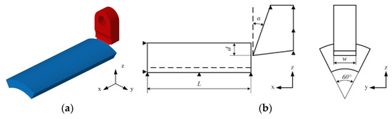
Figure 4.
(a) Tool-tube finite element model and (b) structural parameters.
Figure 4b depicts the geometry and boundary conditions of the tool-tube model. The energy-absorbing tube is simplified to one-sixth by symmetry and given a length of 180 mm to ensure that the cutting temperature reaches a steady state. The geometrical parameters of the tool and the test are identical. The maximum rake angle of the curved tool rake face is 55°. The cutting width and depth are each 27 and 2 mm. The initial speed is 5 m/s, the same as the speed of the test, along the positive direction of the x-axis. The tool’s surface in contact with other parts is constrained with all degrees of freedom except for x-directional movement. The boundary of the tube is fully constrained.
3.1.2. Material Model
Cutting is a highly complex process, and many factors need to be considered, such as the nonlinear properties of materials, etc. No valid numerical simulation method can directly simulate tool failure, and obtaining temperature-dependent material parameters requires many costly experiments. Therefore, the HSS tool is considered an ideal elastic material for numerical simulations in this paper. The energy-absorbing tube is made of S355 steel and simulated with the Johnson–Cook material model. It is widely used in the cutting simulation to simultaneously consider three effects of strain hardening, strain rate strengthening, and temperature softening of metallic materials. The specific equation is
where is the equivalent plastic strain, is the dimensionless plastic strain rate for , and is the homologous temperature, is the room temperature, and is the melting temperature. ,,,, are material constants.
To simulate the separation of metal material in the cutting process, the Johnson–Cook fracture model is determined, and the expression for strain at fracture is given by
where is the ratio of pressure divided by effective stress
Damage to an element is defined by
where is the cumulative plastic strain, and is the fracture strain under the current conditions of stress triaxiality, strain rate, and temperature. A fracture occurs when .
An equation of state is needed for Johnson–Cook to describe how solid materials behave in LS-DYNA. The linear polynomial equation of state is given by
By setting as the bulk modulus and all other terms to zero, the linear polynomial equation of state could achieve simple bulk behavior if strain rates are low to moderate.
The specific values of the Johnson–Cook material model and material thermal properties are presented in Table 1 and Table 2.

Table 1.
Johnson–Cook material parameters for S355 ([32,33]).
Table 2.
Material thermal properties [34].
3.1.3. Mesh Convergence Analysis
In the cutting simulation, the element size is considered very influential [35]. Compared with the cutting length and cutting width, the geometry of the cutting depth direction is the smallest. So, it is determined to be the reference element size of 0.4 mm (not exceeding the tool’s edge radius value of 0.43 mm). The cutting width and length direction sizes are determined according to the solid element aspect ratio of 1:2:2. Therefore, four groups of different element sizes are set as follows: 0.4 × 0.8 × 0.8 mm, 0.2 × 0.4 × 0.4 mm, 0.15 × 0.3 × 0.3 mm, and 0.2 × 0.2 × 0.2 mm.
The force–displacement curves for different element sizes are shown in Figure 5. The cutting force of group 1 is significantly higher than those of other groups. In contrast, groups 2 and 3 are close to each other, indicating that the element size has converged, and further refinement will not significantly improve the calculation accuracy. The comparison between group 2 and group 4 suggests that elements have also converged on the aspect ratio. At last, the element size of 0.2 × 0.4 × 0.4 mm is adopted to balance the computational accuracy and efficiency. The cutting area element size in the simulation model is set to 0.2 × 0.4 × 0.4 mm, and the remaining non-cutting area is 1 × 2 × 2 mm.
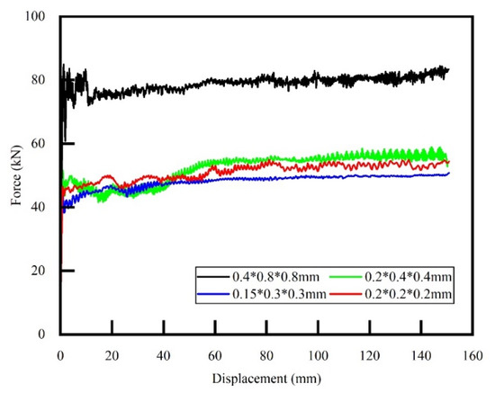
Figure 5.
Force–displacement curves for different element sizes.
3.2. Numerical Simulation Results
3.2.1. Chip Deformation Mode
Chip deformation is an essential indicator of the cutting process and characterizes the quality of the developed numerical model. Figure 6 shows chip deformation at cutting displacements of 50, 100, and 150 mm and compares detailed deformation modes between simulation and experiment. It can be observed that both of them have continuous stripe chips with the same curl shape and the same variation pattern on the chip edges. At the beginning of the chips are both irregular edges generated by the initial unsteady cutting, followed by smoothed edges in the steady-state phase. As the chips continue to be generated and curled, the resistance to chip flow increases and the chips are squeezed, resulting in slightly thick buildups and ragged edges.
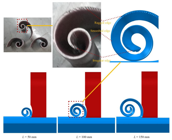
Figure 6.
Chip deformation mode comparison of simulation and test.
3.2.2. Tool Temperature
The distribution of the tool temperature field during the cutting process is shown in Figure 7 below. The heat-resistant temperature of the HSS tool is about 873 K, so the upper limit of the cloud temperature is set to the same value to directly observe the area on the tool that exceeds the heat-resistant temperature. It is evident that the highest temperature zone is always concentrated at the tool’s tip and exceeds the material’s heat-resistant temperature. The area constantly expands, and the parts of the experiment where thermal wear occurs are included, as seen in Figure 2. In contrast, the maximum temperature at the middle of the cutting edge is about 570 K, which is lower than the heat-resistant temperature.
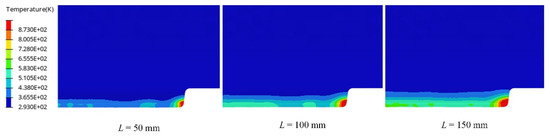
Figure 7.
Tool temperature distribution during the cutting process.
A Python script is developed to extract the maximum value of tool temperature at each moment, and then the tool’s maximum temperature–displacement curve is shown in Figure 8. From 0 to 30 mm (corresponding to the AB segment in Figure 3), the tool temperature increases sharply to 1550 K. After 36 mm, the continuously curling chips accumulate on the front tool face, resulting in increased friction between the tool and the chips. So, the temperature continued to rise slowly. After 107 mm, the maximum tool temperature is stable at 1920 K.
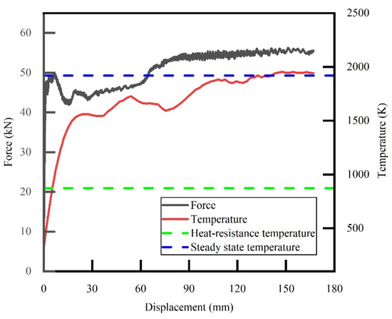
Figure 8.
Curves of force and temperature versus displacement.
The above thermal–structural coupling analysis results reveal that the temperature distribution of the tool is highly consistent with the tool failure mode in the different areas in the test. The failure mode in the middle of the cutting edge at lower temperatures is dominated by mechanical wear. In contrast, thermal wear dominates the failure mode of the tool’s tip above the heat-resistant temperature.
3.2.3. Cutting Force
The tool-tube model’s cutting force versus displacement curve is shown in Figure 8. Compared with the experimental curve (Figure 3), the force of both changes in a similar trend. In the initial stage, from 0 to 30 mm, the cutting force also fluctuates significantly after an initial peak. Its fluctuation frequency is lower than the test (corresponding to the AB segment in Figure 3). From 30 to 83 mm, the cutting state stands in the steady-state stage. The force gradually increases under the effect of chip accumulation. It then stabilizes at about 55 kN, slightly smaller than the steady-state values of the test (340/6 = 56.7 kN) in Figure 3. The simulation cannot directly simulate the real tool failure. Hence, the cutting state remains in the steady-state phase subsequently, and the force stays stable. In contrast, the test showed a continuous increase in force and aggravated oscillation after the steady-state phase. Therefore, the comparison between numerical and experimental results confirms that the worn and broken tool results in decreased cutting performance and increased cutting force and oscillation.
4. Structure Optimization
4.1. New Structure
4.1.1. Design
Based on fracture mechanics, the fracture modes can be divided into three types: Mode I (opening mode), Mode II (sliding mode), and Mode III (tearing mode), as shown in Figure 9. The material of the energy-absorbing tube is sheared and squeezed to form a bent chip during cutting, so the above three fracture modes coexist and act, respectively, on the tool rake, flank, and secondary flank face. The tool’s tip is the common area of these faces. It is often in a biaxial or even triaxial stress state under the combined three fracture modes, which causes its temperature to be greater than any other parts of the cutting edge. Improving the tool tip’s complex stress state during cutting may become vital in reducing its high cutting temperature. A consistent stress state on the cutting edge can be ensured if the chip separation mode at the tip matches that of the rest of the cutting edge. Therefore, this paper proposes a new energy-absorbing tube structure with the following improved structural parameters.
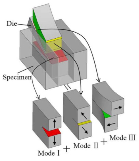
Figure 9.
A schematic of mixed fracture modes involved during the cutting process [21].
As illustrated in Figure 10, a groove is added to the cutting path at the tool’s end with dimensions of 1 mm in width and 2 mm in depth, structurally separating the cutting area from the non-cutting area.
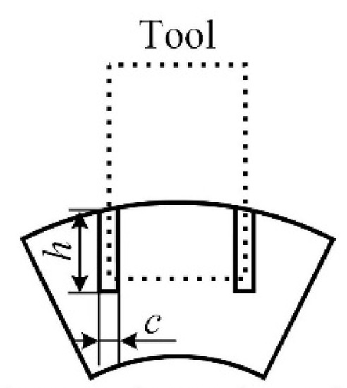
Figure 10.
Schematic diagram of the new energy-absorbing tube cross-section.
4.1.2. Numerical Simulation Verification
The new structure is analyzed using the same thermal–structural coupling method in Section 3. The temperature distribution of the tool is shown in Figure 11. Compared with the original structure, the cutting edge’s temperature does not exceed the heat-resistant temperature of HSS during the cutting process and has a more uniform distribution. Only the temperature in the middle of the cutting edge is slightly higher than in other areas. It will reduce the possibility of tool failure caused by excessive and uneven temperatures.
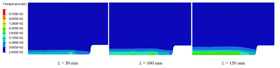
Figure 11.
Tool temperature distribution of the new structure during the cutting process.
The tool’s maximum temperature versus displacement curve is shown in Figure 12. The tool’s maximum temperature reduces to 670 K, which is 65.10% lower than the original structure (1920 K). Moreover, the temperature in the original design increases sharply in the initial phase (0 to 30 mm). In contrast, the temperature rises gently in the new design all the time, which helps reduce tool’s thermal failure due to thermal shock.
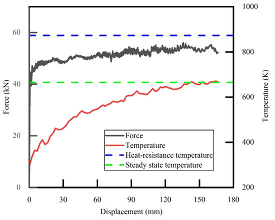
Figure 12.
Curves of force and temperature versus displacement of the new structure.
The cutting force versus displacement curve is shown in Figure 12. The fluctuation of cutting force is significantly weaker than the original from 0 to 75 mm. The steady-state force slightly decreased by 1.85% from 55 kN to 54 kN, and energy absorption decreased by 0.94% from 8.49 kJ to 8.41 kJ. This means that eliminating the tearing fracture mode does not significantly affect the cutting force and energy absorption but enables a more stable cutting process.
The above numerical simulation results indicate that the new structure addressed the problem of the excessive temperature of the tool’s tip at the expense of a small amount of performance. What is more, these improvements help reduce the possibility of tool failure caused by thermal wear and moderate relief of mechanical wear simultaneously.
5. Results
5.1. Multi-Objective Optimization
5.1.1. Multi-Objective Optimization Model
Due to the significant role played by energy-absorbing structures in train collisions, the optimal design of structural crashworthiness has been broadly applied. Commonly used crashworthiness indicators of cutting-type energy-absorbing structures include mean crash force, energy absorption, initial peak force, etc. Tool failure also has a non-negligible impact on the reliability of cutting energy-absorbing structures. In order to consider the reliability and crashworthiness of cutting-type energy-absorbing structures simultaneously, this paper adopts steady-state temperature () and mean cutting force () as optimization objectives, which are defined as follows:
where is the instantaneous cutting force at the distance , and is the total displacement.
The is taken as the steady-state value of the maximum cutting temperature of the tool. It should not exceed 770 K, which can be considered a reasonable value for ensuring that the cutting temperature does not exceed the heat-resistant temperature within a tube length of 180 mm in the tool-tube model.
Considerations for determining the range of the three design variables, cutting depth, width, and tool rake angle, are as follows. The cutting depth is taken from its typical range in machining (approximately 1 to 5 mm). Considering that energy-absorbing structures are usually used on a one-off basis, increasing the depth appropriately to enhance energy absorption by sacrificing its partial durability is acceptable. The depth of cut is therefore set at 2 to 4 mm. Variations in cutting width do not significantly affect the tool’s performance; therefore, only the match to the current structure size usually needs to be considered. For example, in the case of a typical round cross-section energy-absorbing tube, an excessive cutting width at a defined depth of cut will result in thin thickness at both ends, to the detriment of a stable cutting process. In addition, it is necessary to ensure that there should be sufficient spacing between the individual tools, etc. Therefore, the cutting widths are set at 15 to 26.5 mm. The setting of the rake angle takes into account the tool and tube material and the cutting conditions. An increased rake angle means sharper tools and lower cutting temperatures. However, an excessive angle reduces the rigidity and strength of the tool, and bad heat dissipates, resulting in severe wear and breakage. In addition, a rake angle less than zero (negative rake angle) increases cutting force fluctuations and is detrimental to the stability of the energy absorption process. Therefore, in combination with the typical tool rake angle (approximately −10 ~ 30°) in machining and the careful consideration of the collision scenario and performance requirements of the energy-absorbing structure, the tool rake angle is set to 0–30°. Therefore, the mathematical equation of the optimization problem in the multi-objective framework is
5.1.2. Design of Experiment and Surrogate Model
The first step of any population-based optimization is to determine an initial set of sample points by means of design of experiments (DOE) [36]. There are many kinds of DOE methods, including a full factorial design, the Latin hypercube design (LHD), mixture design techniques, and combined design [37]. LHD achieves uniform sampling in multidimensional space and thereby was utilized to sample an initial training set for the surrogate model in this study. Figure 13 illustrates the 20 uniformly distributed sample points obtained by LHD, and Table 3 exhibits the response values obtained from the simulation at the sample points.
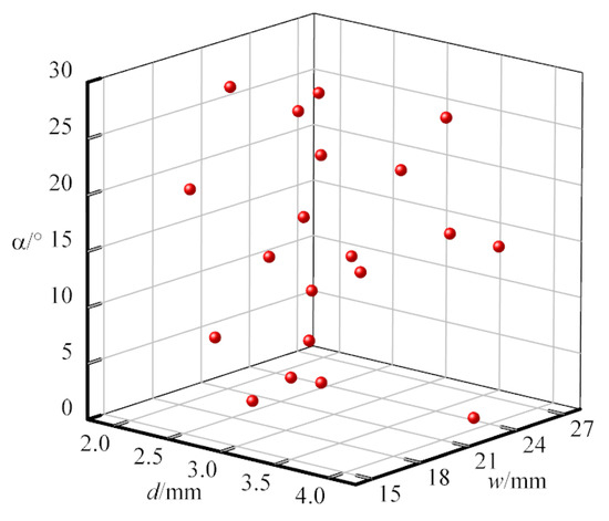
Figure 13.
Schematic diagram of the spatial distribution of sample points.
Table 3.
LHD test sample points and responses values.
Surrogate models have been widely used in design optimization to address the prohibitive computational costs arising from the direct coupling of optimization algorithms and finite element analysis. There are several popular surrogate models, including PRS, Kriging, RBF, artificial neural network (ANN), etc. Analyzing the accuracy of each method from the perspective of problem dimensionality, PRS and RBF work well in low dimensions, and Kriging can handle problems of higher dimensions (<50). When faced with a tremendous dimensional problem (~10,000), ANN may be the best choice [38,39]. In this study, the Kriging model, as one of the most representative and promising models, is utilized due to its good approximation ability to nonlinear functions and unique error estimation function [40]. Two Kriging models of the objective functions are separately established using the sample points determined by LHD method and their response values. The mean relative error () and root-mean-square error (), which indicates the model’s global accuracy, are used to evaluate the error of the surrogate model. These metrics are defined as follows:
where represents the number of sample points, and represent the FE result and the corresponding predicted value at each point i, respectively, and represents the average of the objective responses of the FE calculation. Generally, the model’s accuracy increases with the decreasing and .
The error analysis of the established surrogate model needs to be evaluated by new sample points. They are also randomly sampled and different from the original sample points, as the error of the surrogate model at the original sample points is zero. Hastie et al. [41] suggested taking samples for testing. Five new sample points are used to verify the accuracy of the surrogate model, and the error analysis results are shown in Table 4. Both and are small, indicating that the established surrogate model predicts the target response well and can be adopted for subsequent multi-objective optimization.
Table 4.
Error analysis of surrogate models.
5.1.3. Optimization Method and Results
The multi-objective optimization can be conducted using population-based algorithms directly without formulating a combined cost function [23]. MOPSO and NSGA-II are popular algorithms frequently used in crashworthiness problems [41]. In this study, NSGA-II was adopted to solve the multi-objective optimization problem, and the specific parameters are listed in Table 5.
Table 5.
Parameters of NSGA-II.
The Kriging surrogate model is established for each optimization objective, and the NSGA-II algorithm is utilized to search for the Pareto front, as shown in Figure 14a. The two optimization objectives are competing with each other. When the increases, the decreases. This paper adopts the minimum distance method to determine the optimal solution (also known as the knee point) on the Pareto front. The minimum values of and determine the ideal point. Then, the closest point to the ideal point is identified as the knee point. To minimize the effect of different scales of and on identifying the knee point, the Pareto front is normalized according to
where is the normalized value of the Pareto optimal solution , is the value of the Pareto optimal solution , and and are the minimum and maximum value of the Pareto optimal solution.
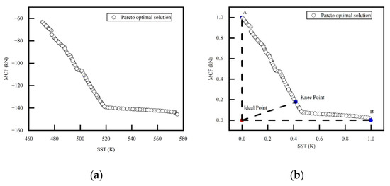
Figure 14.
Pareto front of the multi-object optimization problem. (a) Original Pareto front; (b) normalized Pareto front.
Figure 14b displays the normalized Pareto front. = 514 K and = 131 kN are the values of the objective functions at the knee point. The corresponding design parameters are , , and , respectively. Knee point balanced both and better than point A ( = 470 K, = 63 kN) and point B ( = 575 K, = 146 kN).
6. Conclusions
This paper investigated tool failure modes and causes of the cutting-type energy-absorbing structure using experiments and numerical approaches. A new energy-absorbing tube structure is proposed and optimized for better crashworthiness and reliability. The tool failure modes were identified in the experiments, and the effects of tool failure on the collision responses were analyzed accordingly. The developed numerical model effectively verified the experimentally obtained collision response. Finally, a new energy-absorbing tube structure was proposed by eliminating the tearing-type chip separation mode. The average cutting force and steady-state cutting temperature are optimized using the Kriging surrogate model and NSGA-II algorithm. The main conclusions are as follows:
- Different areas of the tool had different failure modes and causes. In the middle of the cutting edge, the temperature was lower than the heat-resistant temperature, so mechanical wear containing abrasive and adhesion wear occurred primarily. In contrast, the temperature in the tool’s tip and surrounding area exceeded the heat-resistant temperature of the material, so the thermal wear, including transformation and oxidation wear, was mainly: the closer to the tip, the more significant the effect of thermal wear. Thermal wear plays a dominant role in tool failure.
- Tool failure yielded a significant impact on the performance of energy-absorbing structures. The difference in force changing between experimental and numerical results indicated that tool failure led to increasing and oscillating crash forces, which was not conducive to achieving a smooth cutting energy-absorption process.
- The new structure reduced the likelihood of tool failure due to mechanical and thermal wear. By eliminating the tearing mode, it had a significantly lower tip temperature, a more uniform temperature distribution in the cutting edge, and a flatter temperature rising. The cutting force was slightly lower but more stable, so the amount of energy absorption would not be affected. These improvements could better prevent tool failure due to high temperature, thermal shock, thermal unevenness, etc.
- The Pareto front of multi-objective optimization indicates that SST and MCF competed with each other. and could be well balanced by the minimum distance method. The obtained optimal solution was = 514 K, = 131 kN. The corresponding design variables were , , .
- This paper indirectly verified the different tool failure modes by studying the tool’s temperature distribution via thermal–structural coupling finite element analysis. Future research will focus on a realistic simulation of tool failure and further study of the effect of the failed tool on cutting-type energy-absorbing structures.
Author Contributions
Conceptualization, X.W.; methodology and software, Q.G.; validation, X.W.; formal analysis and investigation, Q.G.; resources, M.W.; data curation, S.X.; writing—original draft preparation, Q.G.; writing—review and editing, X.W. and S.X.; visualization, Q.G.; supervision, S.X.; project administration, M.W.; funding acquisition, S.X. and T.Z. All authors have read and agreed to the published version of the manuscript.
Funding
This research was funded by the National Natural Science Foundation of China (grant no. 52175123 and no. 52172409) and the Sichuan Outstanding Youth Fund (grant no. 2022JDJQ0025).
Institutional Review Board Statement
Not applicable.
Informed Consent Statement
Not applicable.
Data Availability Statement
Data available on request due to restrictions.
Conflicts of Interest
The authors declare no conflict of interest.
References
- Gao, G.; Zhuo, T.; Guan, W. Recent Research Development of Energy-Absorption Structure and Application for Railway Vehicles. J. Cent. South Univ. 2020, 27, 1012–1038. [Google Scholar] [CrossRef]
- Gao, G.; Dong, H.; Tian, H. Collision Performance of Square Tubes with Diaphragms. Thin-Walled Struct. 2014, 80, 167–177. [Google Scholar] [CrossRef]
- Yao, S.; Li, Z.; Yan, J.; Xu, P.; Peng, Y. Analysis and Parameters Optimization of an Expanding Energy-Absorbing Structure for a Rail Vehicle Coupler. Thin-Walled Struct. 2018, 125, 129–139. [Google Scholar] [CrossRef]
- Li, J.; Gao, G.; Guan, W.; Wang, S.; Yu, Y. Experimental and Numerical Investigations on the Energy Absorption of Shrink Circular Tube under Quasi-Static Loading. Int. J. Mech. Sci. 2018, 137, 284–294. [Google Scholar] [CrossRef]
- Chung Kim Yuen, S.; Altenhof, W.; Opperman, C.J.; Nurick, G.N. Axial Splitting of Circular Tubes by Means of Blast Load. Int. J. Impact Eng. 2013, 53, 17–28. [Google Scholar] [CrossRef]
- Peng, Y.; Wang, S.; Yao, S.; Xu, P. Crashworthiness Analysis and Optimization of a Cutting-Style Energy Absorbing Structure for Subway Vehicles. Thin-Walled Struct. 2017, 120, 225–235. [Google Scholar] [CrossRef]
- Ning, C.; Guowei, L. Simulation for energy-absorbing process of railway vehicle in metal-cutting way. J. Cent. South Univ. Sci. Technol. 2010, 41, 2444–2450. [Google Scholar]
- Praetzas, C.; Teppernegg, T.; Mayr, J.; Czettl, C.; Schäfer, J.; Abele, E. Investigation of Tool Core Temperature and Mechanical Tool Load in Milling of Ti6Al4V. Procedia CIRP 2018, 77, 118–121. [Google Scholar] [CrossRef]
- Liang, J.; Gao, H.; Xiang, S.; Chen, L.; You, Z.; Lei, Y. Research on Tool Wear Morphology and Mechanism during Turning Nickel-Based Alloy GH4169 with PVD-TiAlN Coated Carbide Tool. Wear 2022, 508–509, 204468. [Google Scholar] [CrossRef]
- Wang, C.Y.; Xie, Y.X.; Qin, Z.; Lin, H.S.; Yuan, Y.H.; Wang, Q.M. Wear and Breakage of TiAlN- and TiSiN-Coated Carbide Tools during High-Speed Milling of Hardened Steel. Wear 2015, 336–337, 29–42. [Google Scholar] [CrossRef]
- Wan, Y. Tool wear and fracutre in high speed milling aluminum alloy 7050-T7451. Chin. J. Mech. Eng. 2007, 43, 103. [Google Scholar] [CrossRef]
- Kai, Y.; Qingshun, B.; Yingchun, L.; Bo, W.; Yazhou, S.; Yan, Z. Damage of Micro-Diameter Cutter While Micro-Milling HPb63-3 Lead Brass. Tribology 2008, 28, 448–452. [Google Scholar]
- Xiao, J. Research on Cutting Performance and Wear Failure Mechanism of Graded Coating HSS Tools. Ph.D. Thesis, Xi’an University of Technology, Xi’an, China, 2007. [Google Scholar]
- Liang, Y.C.; Yang, K.; Bai, Q.S.; Chen, J.X.; Wang, B. Modeling and Experimental Analysis of Microburr Formation Considering Tool Edge Radius and Tool-Tip Breakage in Microend Milling. J. Vac. Sci. Technol. B Microelectron. Nanometer Struct. 2009, 27, 1531. [Google Scholar] [CrossRef]
- Sulaiman, S.; Roshan, A.; Ariffin, M.K.A. Finite Element Modelling of the Effect of Tool Rake Angle on Tool Temperature and Cutting Force during High Speed Machining of AISI 4340 Steel. IOP Conf. Ser. Mater. Sci. Eng. 2013, 50, 012040. [Google Scholar] [CrossRef]
- Zhitao, T.; Zhanqiang, L.; Xing, A.; Xiuli, F. A Study of Thermo-elastic-plastic Large-deformation Finite Element Theory and Key Techniques of Metal Cutting Simulation. China Mech. Eng. 2007, 18, 746–750. [Google Scholar]
- Xia, Q. Thermal-Structure Coupled Analysis and Parameter Optimization of Cutting Energy-Absorbing Process. Master’s Thesis, Central South University, Changsha, China, 2012. [Google Scholar]
- Guowei, L.; Xi, X.; Qianye, W.; Ruling, D. Coupled thermo-structure analysis of cutting energy-absorbing process. J. Vib. Shock. 2015, 34, 93–99. [Google Scholar]
- Yue, C. Study on Energy Absorption Characteristics of Railway Vehicle Broaching Anti-Climber. Master’s Thesis, South China University of Technology, Guangzhou, China, 2014. [Google Scholar]
- Gao, G.; Guan, W.; Li, J.; Dong, H.; Zou, X.; Chen, W. Experimental Investigation of an Active–Passive Integration Energy Absorber for Railway Vehicles. Thin-Walled Struct. 2017, 117, 89–97. [Google Scholar] [CrossRef]
- Guan, W.; Gao, G.; Li, J.; Yu, Y. Crushing Analysis and Multi-Objective Optimization of a Cutting Aluminium Tube Absorber for Railway Vehicles under Quasi-Static Loading. Thin-Walled Struct. 2018, 123, 395–408. [Google Scholar] [CrossRef]
- Guo, L. Study on the Design and Numerical Simulation of the Energy Storage Structure of the Front-end Energy Absorber of Urban. Master’s Thesis, Jilin University, Changchun, China, 2021. [Google Scholar]
- Fang, J.; Sun, G.; Qiu, N.; Kim, N.H.; Li, Q. On Design Optimization for Structural Crashworthiness and Its State of the Art. Struct. Multidiscip. Optim. 2017, 55, 1091–1119. [Google Scholar] [CrossRef]
- Sun, G.; Zhang, H.; Fang, J.; Li, G.; Li, Q. Multi-Objective and Multi-Case Reliability-Based Design Optimization for Tailor Rolled Blank (TRB) Structures. Struct. Multidiscip. Optim. 2017, 55, 1899–1916. [Google Scholar] [CrossRef]
- Wang, J.; Lu, Z.; Zhong, M.; Wang, T.; Sun, C.; Li, H. Coupled Thermal–Structural Analysis and Multi-Objective Optimization of a Cutting-Type Energy-Absorbing Structure for Subway Vehicles. Thin-Walled Struct. 2019, 141, 360–373. [Google Scholar] [CrossRef]
- Peng, Y.; Zhou, J.; Hou, L.; Wang, K.; Chen, C.; Zhang, H. A Hybrid MCDM-Based Optimization Method for Cutting-Type Energy-Absorbing Structures of Subway Vehicles. Struct. Multidiscip. Optim. 2022, 65, 228. [Google Scholar] [CrossRef]
- Ramesh, S.; Viswanathan, R.; Ambika, S. Measurement and Optimization of Surface Roughness and Tool Wear via Grey Relational Analysis, TOPSIS and RSA Techniques. Measurement 2016, 78, 63–72. [Google Scholar] [CrossRef]
- Lu, X.; Zhang, H.; Jia, Z.; Feng, Y.; Liang, S.Y. Cutting Parameters Optimization for MRR under the Constraints of Surface Roughness and Cutter Breakage in Micro-Milling Process. J. Mech. Sci. Technol. 2018, 32, 3379–3388. [Google Scholar] [CrossRef]
- Li, N.; Sheikh-Ahmad, J.Y.; El-Sinawi, A.; Krishnaraj, V. Multi-Objective Optimization of the Trimming Operation of CFRPs Using Sensor-Fused Neural Networks and TOPSIS. Measurement 2019, 132, 252–262. [Google Scholar] [CrossRef]
- German Version EN 15227:2008+A1:2010; Railway Applications—Crashworthiness Requirements for Railway Vehicle Bodies. iTeh, Inc.: Etobicoke, ON, Canada, 2011.
- Sarhan, A.; Sayed, R.; Nassr, A.A.; El-Zahry, R.M. Interrelationships between Cutting Force Variation and Tool Wear in End-Milling. J. Mater. Process. Technol. 2001, 109, 229–235. [Google Scholar] [CrossRef]
- Forni, D.; Chiaia, B.; Cadoni, E. High Strain Rate Response of S355 at High Temperatures. Mater. Des. 2016, 94, 467–478. [Google Scholar] [CrossRef]
- Forni, D.; Chiaia, B.; Cadoni, E. Strain Rate Behaviour in Tension of S355 Steel: Base for Progressive Collapse Analysis. Eng. Struct. 2016, 119, 164–173. [Google Scholar] [CrossRef]
- Gaskell, D.R. Introduction to the Thermodynamics of Materials, 4th ed.; Taylor & Francis: New York, NY, USA, 2003; ISBN 978-1-56032-992-3. [Google Scholar]
- Ambati, R.; Yuan, H. FEM Mesh-Dependence in Cutting Process Simulations. Int. J. Adv. Manuf. Technol. 2011, 11, 313–323. [Google Scholar] [CrossRef]
- Kaps, A.; Czech, C.; Duddeck, F. A Hierarchical Kriging Approach for Multi-Fidelity Optimization of Automotive Crashworthiness Problems. Struct. Multidiscip. Optim. 2022, 65, 114. [Google Scholar] [CrossRef]
- Huang, H.; Yang, X.; Yan, Q.; Xiang, Z.; Xu, S. Crashworthiness Analysis and Multiobjective Optimization of Bio-Inspired Sandwich Structure under Impact Load. Thin-Walled Struct. 2022, 172, 108840. [Google Scholar] [CrossRef]
- Simpson, T.W.; Poplinski, J.D.; Koch, P.N.; Allen, J.K. Metamodels for Computer-Based Engineering Design: Survey and Recommendations. Eng. Comput. 2001, 17, 129–150. [Google Scholar] [CrossRef]
- Kudela, J.; Matousek, R. Recent Advances and Applications of Surrogate Models for Finite Element Method Computations: A Review. Soft Comput. 2022, 26, 13709–13733. [Google Scholar] [CrossRef]
- Hastie, T.; Tibshirani, R.; Friedman, J. The Elements of Statistical Learning; Springer Series in Statistics; Springer: New York, NY, USA, 2009; ISBN 978-0-387-84857-0. [Google Scholar]
- Albak, E.İ. Crashworthiness Design and Optimization of Nested Structures with a Circumferentially Corrugated Circular Outer Wall and Inner Ribs. Thin-Walled Struct. 2021, 167, 108219. [Google Scholar] [CrossRef]
Disclaimer/Publisher’s Note: The statements, opinions and data contained in all publications are solely those of the individual author(s) and contributor(s) and not of MDPI and/or the editor(s). MDPI and/or the editor(s) disclaim responsibility for any injury to people or property resulting from any ideas, methods, instructions or products referred to in the content. |
© 2023 by the authors. Licensee MDPI, Basel, Switzerland. This article is an open access article distributed under the terms and conditions of the Creative Commons Attribution (CC BY) license (https://creativecommons.org/licenses/by/4.0/).