Abstract
The article presents the results of experiments aimed at finding the displacement of a cylinder being part of a boom system, as recorded after initiating a rapid breaking process. The tests were performed on a special test stand which allows modifications of the control system architecture. The article presents a comparative analysis of three systems different with respect to their architecture and use of control valves. It discusses the test results and the influence of the architecture of a hydrostatic system on the accuracy of the resultant position of the working element. The article also describes the influence of external loads on the working movement accuracy of the tested systems. The results allow the author to relate the structure of a hydraulic system to the parameter of the obtained working movement accuracy with respect to the maximum values of pressures and dynamic forces.
1. Introduction
Hydrostatic power systems used in machines are being simultaneously developed in several areas. The greatest emphasis seems to be placed on the development of solutions which allow reduced power consumption by offering higher system efficiencies. Research in this area is performed in such aspects as increasing the efficiencies of individual elements [1,2,3,4,5], changing liquid parameters [6] or modifying the architecture of the entire systems [7,8,9,10,11,12]. Some research works are also performed into thermal phenomena which occur in hydrostatic systems [13,14]. The majority of the above indicated development works consider or directly involve changes in the architecture of hydraulic systems. Such modifications allow the researchers to reach the defined goals. However, they also affect other parameters of hydrostatic power systems, e.g., the stiffnesses of the operating elements, the pressure values recorded in the system during operation, and the character of the movements of the operating elements, including the movement control and monitoring methods [15,16,17,18]. The broadly understood development process of hydrostatic power systems should take into perspective all of these aspects and moreover also the cost- and maintenance-related issues. One of the important parameters is the actual accuracy of the cylinder working movements, which depends inter alia on the system architecture, and particularly on the type and physical position of the control valves in the system The fact that architecture changes affect the accuracy of the cylinder movement should be linked with an assumption that the control valves may be opened for a short period of time due to the dynamically applied external load and the resulting dynamic pressure changes. Analyzing relationships between these dynamic interactions in a hydraulic system from the perspective of a broad range of phenomena resulting from these interactions seems an interesting and still insufficiently explored object of research. The study presented in this paper represents a new and original approach to the above research problem. Moreover, identification of the relationship between the system architecture and the accuracy of the working movements seems to be an indispensable part of the process of developing hydrostatic systems.
2. Background
The movement accuracy of the working system is frequently crucial to the accuracy and efficiency of technological processes. In the case of machines with boom systems and hydrostatic power systems this issue is of particular importance. Prior research and development works performed by the author demonstrated that the implementation of new monitoring or control solutions on the level of hydrostatic power system does not always guarantee the expected operating efficiency parameters [19]. Contradictory requirements defining on the one hand the process speed and on the other hand the positioning accuracy of the work system represent a significant challenge to modern hydrostatic power systems. Moreover, the introduced changes should have a positive effect on the obtained efficiencies of the system, and this requirement practically eliminates throttling control, which is commonly used in classic solutions in order to reach the required working movement accuracies. Research works carried out in this direction resulted in the development of new self-contained electro-hydraulic actuator (EHA) systems whose operating parameters, including the movement accuracy has been improved in comparison with the parameters of the classical solution [8,16]. However, the described and tested solutions had complex hydraulic control systems and hydraulic accumulators. Therefore, further work in this area was aimed at reducing the complexity of the EHA hydraulic control system, which translated into both the reduction of cost and the limitation of space necessary for installation [18]. Minimizing the number of hydraulic control elements thus seems to be beneficial and the development of such hydraulic systems is a promising research direction.
3. Problem Analysis
3.1. Model of the Cylinder Control System
The classic approach to the design of hydraulic systems typically does not allow for the influence of the position of control valves with respect to the operating element and the power source. The above fact results from the assumption of a quasi-static model of flows and pressure changes in the system. In effect, during the design phase, the mutual position of the hydrostatic system elements, in the classic approach, is typically dictated by the geometry-related requirements of the driven machine. Incorporating dynamic phenomena in the analysis of hydrostatic systems is currently one of the most intensively followed directions in the development of both individual elements and the entire systems. It broadens the scope of the analysis and allows predictions of such adverse phenomena as hydraulic shocks, momentary significant pressure increases or resonance in the system. In such analysis, the mutual position of the system elements is one of the basic input variables, as demonstrated in the results of comparative analyses [16]. The position of the control elements has an impact on the recorded stiffness of the cylinders and thus on the recorded maximum pressure values at the moment of valve switching [20]. However, although a significant number of research works focus on the analysis of individual elements of hydraulic systems, some research works, including this, focus more narrowly on the mutual interactions between the elements in a hydraulic system. During the development works, the accuracy of the cylinder movements was found to depend not only on the architecture of the system, but also on the extend of external loads acting on the hydraulic cylinder. The influence of accelerations and the resulting inertia forces recorded during velocity changes of the driven element should be allowed for along with the influence of the resulting pressure changes on the operation of the hydraulic valves, and thus on the possibility of fluid flow through the valves, as an effect of this type of processes, should also be taken into account. Such formulation of the research problem allows the characteristics of a hydraulic system to be interrelated with external excitations, which have a secondary influence on the dynamic aspects of its operation. This phenomenon may be observed inter alia in the case of stopping boom systems in required positions. The characteristics of the recorded system movement should be different depending on the valves installation location and control methods, with the individual architectures of the system ensuring the best movement accuracy levels in certain ranges of variable pressure loads. This thesis has been verified by measuring the response of the system to the switching of the valves and to the stopping of the work system during the lifting of a boom system loaded with variable masses. This phenomenon was analyzed in more detail in an experiment whose results are presented below. Three control hydraulic system architectures were tested on the same research hydraulic system test stand. The first was a classic system controlled by a spool valve moved away from the cylinder. The second was a system with a pair of 2-way simultaneously controlled valves mounted on the cylinder. In order to determine the impact of pressure changes on valves mounted in series directly next to the cylinder, the tests also involved a third system which is controlled only by means of a 2-way valve mounted on the actuator supply line. The responses of the dynamic system (Figure 1) were measured as a function of time and in relation to the response time of the system after changing the valve control signal.
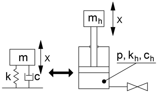
Figure 1.
Basic physical model of the analogy of a hydraulic cylinder and a second-order dynamic system.
The model shown in Figure 1 is an entirely acceptable approximation in the case of full and hermetic closure of the power supply line, if assumed that the pressure values of liquid in the cylinder chamber and in the power supply line (p) are identical. In such case, the parameters of the second-order dynamic hydraulic system depend on the following variables:
k—stiffness parameter of the dynamic system,
kh—stiffness parameter of the hydraulic system,
Ec—bulk modulus of the liquid,
Vc—volume of the confined liquid,
El—modulus of elasticity of the power supply line.
c—damping parameter of the dynamic system,
ch—damping parameter of the hydraulic system,
Ff—mechanical friction in the cylinder,
Fc—viscous friction value in the liquid.
The stiffness and damping parameters of the hydraulic and dynamic systems can be identified empirically, by analyzing responses of the dynamic system. However, such analysis should be based on the responses recorded over a time period in which the control valve is certainly and completely closed. The moment when the valve closes completely is not identical to the moment in which the valve control signal changes, and the period between the signal change and the actual complete closure of the valve may be sufficiently long to affect the accuracy of the cylinder movement. It is therefore justified to extend the dynamic model of a hydraulic system with a function related to the valve characteristics (Figure 2).
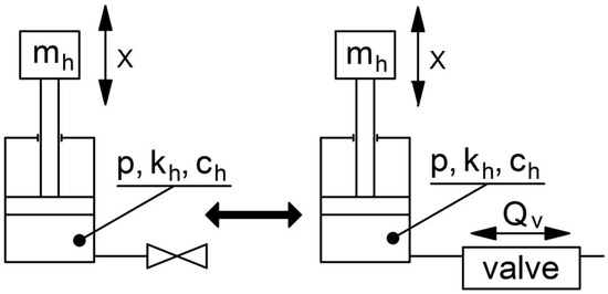
Figure 2.
Dynamic model of a hydraulic system with allowance for the dynamic response of the valve.
Momentary flow (Qv) is here understood as a short-lasting flow of liquid through the valve reconfigured into the closed position. This flow is probably caused by the momentary opening of the valve due to variable pressure in the chamber and in the power supply line. This pressure value is referred to as the momentary value of the pressure Δp(t). In the model shown in Figure 2, the value of momentary flow rate in the control valve can be described as a function of the following parameters:
Is(t)—valve control signal value in time.
Importantly, the momentary flow rate value recorded on the valve generates hydrodynamic forces which also influence the characteristics of the valve response to the control signal change. An experiment which would allow a precise identification of momentary flow rates seems problematic. However, the total volume of the liquid flowing through the valve to the cylinder (Qvac) is directly proportional to the cylinder extension value (Δxac) recorded after the valve is switched to the closed position.
The above relationship, with assumed identical dimensions and within the range of internal resistances in the investigated cylinder, allows an empirical comparative analysis of the systems on the basis of the measured values of piston rod displacements in the cylinder after the stopping process has been initiated.
3.2. Architecture of the Analyzed System
The above-mentioned time-dependent parameters affecting the system control valve also depend on the architecture of the system. This research has focused on analyzing the responses of a system having three different architectures. The tested system could control a loaded hydraulic cylinder in three different architectures without changing the object of the tests. This was possible by using a dedicated test stand and a special solution of the cylinder power supply system [21]. The resultant hydraulic system used in the presented tests was provided with both a spool valve and 2/2 way valves installed on the cylinder (Figure 3). Moreover, the system was provided with a laser displacement sensor, which served to identify the extension of the cylinder piston rod. The forces were measured on a rod which connected the eye of the cylinder piston rod to the loading boom system. The tests provided information on the responses of the system to the signal stopping the extension of the cylinder in three different architectures of the control system. The first solution was a classic control system employing a four-way spool valve (Figure 3a) with constantly open two-way valves installed on the cylinder. In the second tested solution, the stop signal was simultaneously sent to two two-way valves which were installed on the cylinder and which disconnected both the power supply line and the return line of the cylinder (Figure 3b). In the third tested solution, the stop signal was sent only to the two-way valve located on the cylinder power supply line (Figure 3c). Importantly, each stop signal was a negative signal, i.e., a signal to disconnect power from the control electromagnets, as a result of which the influence of the electromagnet characteristics could be neglected. The basic elements used in the system are listed in Table 1.
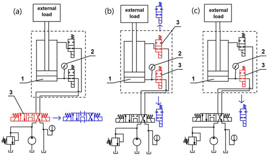
Figure 3.
Simplified schematic diagram of the cylinder-stopping control systems: (a)—employing a spool valve (first tested solution), (b)—employing two directional control valves (second tested solution), (c)—employing a single directional controlled valve (third tested solution); the controlled valves are indicated in red, the valves positions after initiating the stopping process are indicated in blue; no. 1 indicates the cylinder, no. 2 indicates the pressure transducer, and no. 3—the controlled valves.

Table 1.
Basic elements of the system.
During the tests, the achieved pressure range was intentionally shifted far from the maximum pressure of the system in order to be able to eliminate the impact of phenomena occurring in valves loaded with pressure close to or exceeding the maximum value. In addition, the selected range of pressure enabled the identification of changes in the movement accuracies as a function of the external load for the three tested systems.
3.3. The Test Procedure
A new test procedure was designed to correctly identify the influence of the system architecture on the accuracy of cylinder movements. As the tests indirectly involved the phenomenon of mutual interactions between the control elements and the hydraulic cylinder, an assumption was made that the experiment results will be subjected to a comparative analysis with the use of statistical tools. This approach resulted from the fact that the accuracy of the hydraulic cylinder movements is affected by a number of factors, such as the temperature, and thus also the viscosity of the liquid, the design and dynamic characteristics of the valves, momentary value of mechanical and hydraulic energy in the system, the influence of the pressure load on the dynamic response of the valves, etc. Not all of such relationships are currently known and described, as for example is the effect of possible temporary opening of the valves due to the variable pressure load and not to the control signal. Moreover, some parameters, such as the liquid temperature, are variable in time and change during the tests. Therefore, in order to ensure possibly constant test conditions, the proposed test procedure involved a limited number of repetitions, which still allowed the comparative analysis with the use of statistical tools.
The control system sent the signal to close the valve at the moment when the cylinder reached its preset extended position. During the tests, the cylinder started its movement from the completely retracted position. In the next step, hydraulic power was supplied to the piston chamber and simultaneously the piston rod chamber was connected to the reservoir. After the cylinder reached the maximum extension speed of 75 mm/s and the preset extension of 95 mm, the control system disconnected the power supply to the coil (first and third solution) or to the coils (second solution). Five test cycles were performed for five different loads of the boom system (Figure 4). Each of the cycles served to measure the responses of the system in all three control system architectures. Each measurement was performed three times. The measured signals were recorded at a frequency of 500 Hz.
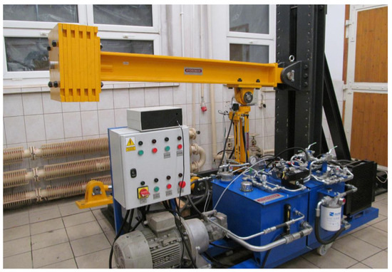
Figure 4.
Test stand with visible loading masses.
The pressure relief valves were set to 20 MPa. During the tests, the hydraulic oil temperatures remained within a range from 45 to 55 °C. The oil was heated in a circuit which allowed for the flow through the valves and the cylinder.
4. Test Results
In order to ignore the effect of potential inaccuracies related to delays caused by the sensitivity of the laser rangefinder and by the response of the electronic control system, the analysis focused on the movement action after the switching of the valves was confirmed. The beginning of the valve-closing process was identified on the basis of the detected beginning of the first significant change of force recorded on the measurement rod of the cylinder. This was a clear indication of the beginning of the system-stopping process (Figure 5). The pressure propagation wave phenomenon observed in the architecture of the classic (first) solution caused a certain delay in the recorded pressure change with respect to the beginning of force change on the cylinder. The analysis involved the displacement value of the cylinder piston rod recorded at the beginning of the stopping process as a function of load and system architecture.
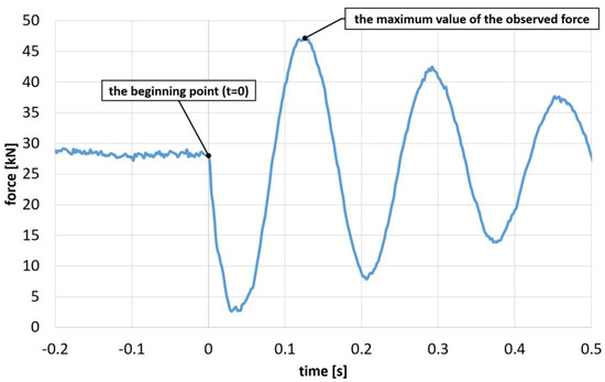
Figure 5.
Representative curve of force changes recorded on the measurement rod of the cylinder with the indicated point marking the beginning of the analysis (t = 0).
The test results demonstrated that in the analyzed cases the cylinder oscillation always stopped within a time period no longer than 0.2 s after the stopping process was initiated. However, the changes of pressure and force values were observed over a longer period. The results thus confirm the preliminary thesis that the impact of the variable pressure on the valves in the first phase of the cylinder stopping process results in their temporary opening despite the lack of the relevant control signal. Therefore, the analysis of the variability of displacement as a function of the system architecture and load was enabled by reading the average value of the measured extension value for the period of 0.2 to 0.25 s after the stopping process was initiated (t = 0). As a result, the following displacement values were obtained (Table 2).
Table 2.
Measurement results of the cylinder displacement after initiating the stopping process, in mm.
The maximum values of the observed forces and pressures (Figure 6) in the cylinder power supply line were also identified. The relationships between the individual average values are shown in the following graphs (Figure 7 and Figure 8). They demonstrate that during the cylinder stopping action the relationship between the maximum pressure values as a function of the maximum recorded forces is linear and practically independent of the architecture type of the system. However, the maximum recorded pressure and force values as a function of the loading mass are different. This is due to the fact that in the first, classic system the influence of the compliance of the power supply line and of the compressibility of the liquid present in this line is already significant. Moreover, the similarity of the pressure changes as a function of force indicates that in the investigated cases internal resistance values in the cylinder are comparable. Therefore, the presented experiment allows a direct relationship to be established between the differences of the recorded parameter values and the architecture of the hydrostatic system.
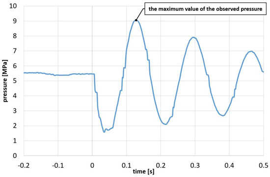
Figure 6.
Representative curve of pressure changes in the piston chamber of the cylinder with the indicated maximum value.
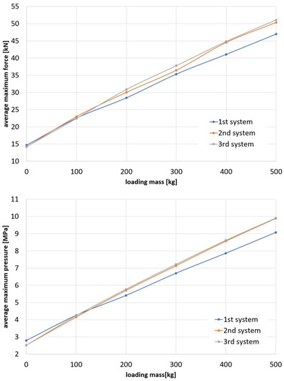
Figure 7.
Average values of the maximum recorded pressure and forces as a function of the loading mass.
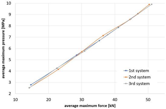
Figure 8.
Mutual variability of the pressure and forces average values.
On the other hand, a comparison of the average results for the cylinder piston rod displacement after the initiation of the stopping process, expressed as a function of external loading, indicates significant tendency changes (Figure 9). They allow an observation that lower movement values were obtained in the case of systems number two and three and for limited loads, while system number one showed lower movement values at increased loads.
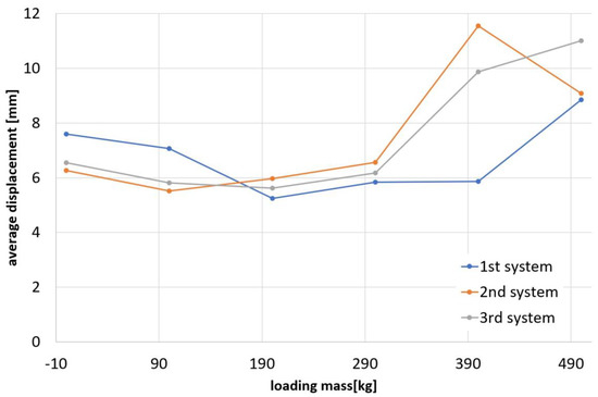
Figure 9.
Average cylinder piston rod displacement values recorded after the initiation of the stopping process, expressed as a function of the loading mass.
In order to identify the advantageous movement values for each of the systems, the structure of the work system and the dynamic compliance were ignored, and the obtained average movement values were compared to the maximum force and pressure values in the system (Figure 10).
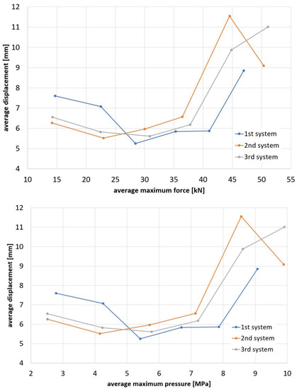
Figure 10.
Average cylinder piston rod displacement values recorded after the initiation of the stopping process, expressed as a function of the maximum forces and pressure.
The obtained results were the basis for statistical analysis, which provided further information used to formulate final conclusions.
5. Discussion
The convergence areas for the measurement results were identified with the use of statistical analysis. The standard deviation of the results from the population was determined on the basis of normal probability distribution, and then confidence intervals were determined for a confidence level of 95 %. As each of the measurements was repeated three times, the confidence intervals were analyzed with the Student’s T distribution. The analysis results are listed in Table 3 and graphically represented in Figure 11.
Table 3.
Results of the statistical analysis for the T Student distribution in the 95% confidence interval, in millimeters.
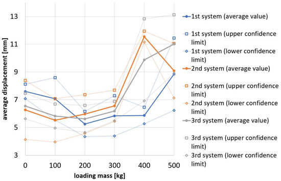
Figure 11.
Confidence intervals with approximations, calculated for the confidence level of 95%, together with the average values of cylinder piston rod displacements recorded after the start of the stopping process, expressed as a function of the loading mass.
The statistical analysis clearly indicates that the results differ and three ranges of loads can be distinguished, leading to the following conclusions. The first conclusion refers to the load range from zero to 100 kg, corresponding to the registered maximum pressures range from 2.5 to about 4.5 MPa, i.e., the value equal to approximately 15% of the maximum pressure value in the control valve. Statistical analysis shows that in this range of loads the greatest piston rod displacement after the initiation of the stopping action is observed in solution 1. As the loads increase, the differences between the tested systems become less significant and within the maximum pressure range of 4.5 to approximately 7.5 MPa the confidence intervals are comparable for all three systems. As the loads are further increased, within the maximum pressure range of 7.5 to approximately 9.5 MPa, the average displacement values increase for all solutions, while the confidence interval of solution 1 does not overlap with the confidence intervals of solutions 2 and 3. In this load range solution 1 shows a tendency for the smallest displacement value.
Importantly, although the test parameters were not modified, the results of measurements performed for greater loads acting on the system begin to differ significantly from each other. The author believes that this effect may be linked to the fact that as the cylinder stops, the opening of the valve is a discontinuous process related to repeated temporary opening of the valve due to variable pressure. The dynamic response of the valve moving element seems to allow the valve to open a greater number of times during the cylinder stopping process, and each such opening action is reflected in the displacement of the piston rod. The different results observed at higher loads are probably due to pressure variations which cause a greater number of irregular temporary valve opening actions. Further analysis of the relationships between the pressure variations and the dynamic phenomena in hydraulic valves operating in hydrostatic systems is an interesting research direction and is continued by the author.
The presented test results demonstrate that the positioning accuracy of the hydraulic cylinders obtained for various system architectures has favorable values in certain load ranges. The results of the statistical analysis indicate that a general assumption that one of the analyzed systems will always ensure greater accuracy of the actuator movements is therefore incorrect. The analysis of the accuracy of the hydraulic cylinder movements should therefore also allow for the dependence of this parameter on the extent and variability of pressures affecting the valve system as a result of external load changes. The described results should be associated with the impact of hydrodynamic phenomena, such as the interaction of the valves and the hydraulic cylinder connected in and the resulting possible occurrence of additional pressure loads on the control valves (solution 1 and 2). Determining the exact and useful mathematical models in this area seems to be a new and promising research direction. In addition, the results indicate that it is reasonable to consider, especially in the range of pressures significantly lower than the nominal valve pressures, the use of a control system with one control valve on the supply line (solution 3). In this configuration the system stiffness can be improved while avoiding the adverse effect of interactions between the valves.
6. Conclusions
The test results demonstrate that the architecture of a hydrostatic system, and hence a change in the interactions and their range between its individual elements, has an influence on the accuracy of the working movements performed by the cylinder also in terms of external loads. In the analyzed case, the differences of average displacement values measured after the initiation of the stopping process showed differences, the significance of which was confirmed by statistical analysis. The presented results indicate that the position of the control valve away from the cylinder, as is the case in classic solutions, is not disadvantageous over the entire load range. It was additionally observed that within the investigated range, the displacement difference between a system controlled only by the valve in the power supply line and a system controlled by simultaneously closing the valves in the power supply line and in the return line is not as significant as the difference between these systems and the classic system with a spool valve moved away from the cylinder. The presented results demonstrate that the simultaneous control of the flow in both the power supply and return lines is not the most advantageous solution within a low load range, in which the interaction of the valves and the cylinder connected in series is a significant phenomenon. The presented test procedure and the test results indicate the importance of extending the analysis of the relationships between the system architecture and the obtained accuracies of cylinder working movements by including the load and pressure ranges. This knowledge can be used in further development works on the elements, architecture and control algorithms in individual hydrostatic systems.
Funding
This research received no external funding.
Institutional Review Board Statement
Not applicable.
Informed Consent Statement
Not applicable.
Data Availability Statement
The data presented in this article are available on request from the author.
Acknowledgments
Not applicable.
Conflicts of Interest
The author declares no conflict of interest.
References
- Quan, Z.; Quan, L.; Zhang, J. Review of energy efficient direct pump controlled cylinder electro-hydraulic technology. Renew. Sustain. Energy Rev. 2014, 35, 336–346. [Google Scholar] [CrossRef]
- Heitzig, S.; Sgro, S.; Theissen, H. Energy Efficiency of Hydraulic Systems with Shared Digital Pumps. Int. J. Fluid Power 2012, 13, 49–57. [Google Scholar] [CrossRef]
- Kauranne, H. Effect of operating parameters on efficiency of swash-plate type axial piston pump. Energies 2022, 15, 4030. [Google Scholar] [CrossRef]
- Liu, J.; Li, R.; Ding, X.; Liu, Q. Flow Force Research and Structure Improvement of Cartridge Valve Core Based on CFD Method. Heliyon 2022, 8, e11700. [Google Scholar] [CrossRef] [PubMed]
- Dimitrov, S.; Krstev, D. Modelling and Simulation of the Transient Performance of a Direct Operated Pressure Relief Valve. Hidraulica 2022, 5, 75–81. [Google Scholar]
- Quilumba, F.L.; Lee, L.K.; Lee, W.-J.; Harding, A. Improving Hydraulic System Energy Efficiency with High-Performance Hydraulic Fluids. IEEE Trans. Ind. Appl. 2014, 50, 1313–1321. [Google Scholar] [CrossRef]
- Ge, L.; Quan, L.; Li, Y.; Zhang, X.; Yang, J. A novel hydraulic excavator boom driving system with high efficiency and potential energy regeneration capability. Energy Convers. Manag. 2018, 166, 308–317. [Google Scholar] [CrossRef]
- Hagen, D.; Padovani, D.; Choux, M. A Comparison Study of a Novel Self-Contained Electro-Hydraulic Cylinder versus a Conventional Valve-Controlled Actuator—Part 2: Energy Efficiency. Actuators 2019, 8, 78. [Google Scholar] [CrossRef]
- Minav, T.A.; Laurila, L.I.E.; Pyrhönen, J.J. Analysis of electro-hydraulic lifting system’s energy efficiency with direct electric drive pump control. Autom. Constr. 2013, 30, 144–150. [Google Scholar] [CrossRef]
- Zhang, S.; Minav, T.; Pietola, M.; Kauranne, H.; Kajaste, J. The effects of control methods on energy efficiency and position tracking of an electro-hydraulic excavator equipped with zonal hydraulics. Autom. Constr. 2019, 100, 129–144. [Google Scholar] [CrossRef]
- Wang, H.; Yang, S.; Lu, T. Performance-Matching Optimization Design of Loader-Hydraulic System Based on Hydrodynamics Analysis. Processes 2022, 10, 1524. [Google Scholar] [CrossRef]
- Zhang, K.-C.; Shi, J.-Y. Pulsation Simulation and Energy Consumption Analysis of Series Pump Valve Cooperative Control Hydraulic System. Int. J. Fluid Power 2021, 22, 409–424. [Google Scholar] [CrossRef]
- Yi, T.; Ma, F.; Jin, C.; Hong, J.; Liu, Y. Investigation on Thermal Characteristics of the Oil-Circulating Hydraulic Energy Storage System for Hybrid Mining Trucks. Front. Energy Res. 2021, 9, 733919. [Google Scholar] [CrossRef]
- Siwulski, T.; Warzyńska, U.; Moraś, Ł.; Rosikowski, P.; Pac, P. Modeling of Liquid Exchange Process in a Hydraulic Cylinder Chamber in the Aspect of Power System. In Proceedings of the 14th International Scientific Conference: Computer Aided Engineering, Polanica Zdrój, Poland, 20–23 June 2019; pp. 653–660. [Google Scholar]
- Schmidt, L.; Groenkjaer, M.; Pedersen, H.C.; Andersen, T.O. Position Control of an Over-Actuated Direct Hydraulic Cylinder Drive. Control Eng. Pract. 2017, 64, 1–14. [Google Scholar] [CrossRef]
- Hagen, D.; Padovani, D.; Choux, M. A Comparison Study of a Novel Self-Contained Electro-Hydraulic Cylinder versus a Conventional Valve-Controlled Actuator—Part 1: Motion Control. Actuators 2019, 8, 79. [Google Scholar] [CrossRef]
- Shen, W.; Wang, J.; Huang, H.; He, J. Fuzzy sliding mode control with state estimation for velocity control system of hydraulic cylinder using a new hydraulic transformer. Eur. J. Control 2019, 48, 104–114. [Google Scholar] [CrossRef]
- Qu, S.; Zappaterra, F.; Vacca, A.; Liu, Z.; Busquets, E. Design and Verification of an Open-Circuit Electro-Hydraulic Actuator System with an Integrated Electro-Hydraulic Unit. In Proceedings of the 13th International Fluid Power Conference (13. IFK), Aachen, Germany, 21–23 March 2022. [Google Scholar]
- Siwulski, T. Accuracy of Work Tool Position Measurement by Means of a Drilling Monitoring System. J. Mach. Eng. 2018, 18, 57–67. [Google Scholar] [CrossRef]
- Siwulski, T. Comparative studies of the dynamic response of hydraulic cylinders with different hydraulic supply systems design. In Advances in Hydraulic and Pneumatic Drives and Control 2020; Stryczek, J., Warzyńska, U., Eds.; Springer: Cham, Switzerland, 2021; pp. 301–310. [Google Scholar]
- Siwulski, T.; Warzyńska, U.; Ryś, M.; Skrzypczak, M. Experimental tests of fluid exchange process improvement in a new design of hydraulic cylinder with a supply system. In Proceedings of the 12th International Fluid Power Conference (12. IFK), Dresden, Germany, 12–14 October 2020; pp. 199–208. [Google Scholar]
Disclaimer/Publisher’s Note: The statements, opinions and data contained in all publications are solely those of the individual author(s) and contributor(s) and not of MDPI and/or the editor(s). MDPI and/or the editor(s) disclaim responsibility for any injury to people or property resulting from any ideas, methods, instructions or products referred to in the content. |
© 2023 by the author. Licensee MDPI, Basel, Switzerland. This article is an open access article distributed under the terms and conditions of the Creative Commons Attribution (CC BY) license (https://creativecommons.org/licenses/by/4.0/).