


Making a Case for Hybrid GFRP-Steel Reinforcement System in Concrete Beams: An Overview


Abstract
1. Introduction
2. Background
2.1. Steel Deterioration in RC Beams
2.2. Fibre Reinforced Polymers (FRP) as Alternative Reinforcement in RC Beams
3. Analytical Models for Hybrid GFRP-Steel Reinforced Beams
3.1. Models Considering Mechanical Effects
3.1.1. Ductility Analysis
3.1.2. Crack Width Analysis
3.1.3. Flexure Modelling
3.1.4. Shear Design
3.2. Models Considering Physical Effects: Fire Modelling
4. Outlook for Future
- Investigation of the factors that control the activation of ductile behaviour in steel reinforcement in hybrid reinforcement arrangements.
- Experimental studies on GFRP shear reinforcement (stirrups) incorporated with hybrid reinforcement systems.
- Experimental and numerical studies on the effects of different grades of steel on ductility development in hybrid GFRP–steel RC beams.
- Investigation of the behaviours of hybrid GFRP-steel reinforcement systems to varying temperature gradients and their recovery.
- Investigations on the long-term durability of GFRP bars.
- Numerical modelling of the effects of bond-slip behaviour of GFRP in hybrid RC systems.
- Experimental and numerical studies of the effects of the surface characteristics of GFRP bars on the structural performance of hybrid RC beams.
5. Conclusions
- The inherent corrosive nature of steel is a threat to the durability of RC structures, specifically in aggressive environments. The FRPs, which has high strength-to-weight ratio than steel, are one of the most suitable solution to enhance the durability of RC structures.
- GFRP is an economically viable option for the usual commercial applications. Although its properties are not as competent as other FRP variants such as CFRP and BFRP, it is proven to be more efficient than using conventional steel bars, especially in harsh environments.
- Lack of ductility is one of the characteristic traits that questions the application of GFRP bars in flexure beams, where flexural yield is a demanding behaviour to design safe structures. Despite proposing new parameters to quantify the ductility of GFRP-steel RC beams, the studies explaining the synergetic mechanism between the GFRP and steel is very limited.
- The crack developments in the hybrid beams are highly dependable on the bond co-efficient used in the design. Hence, it is important to understand the bond behaviour between the GFRP bars used in the hybrid system.
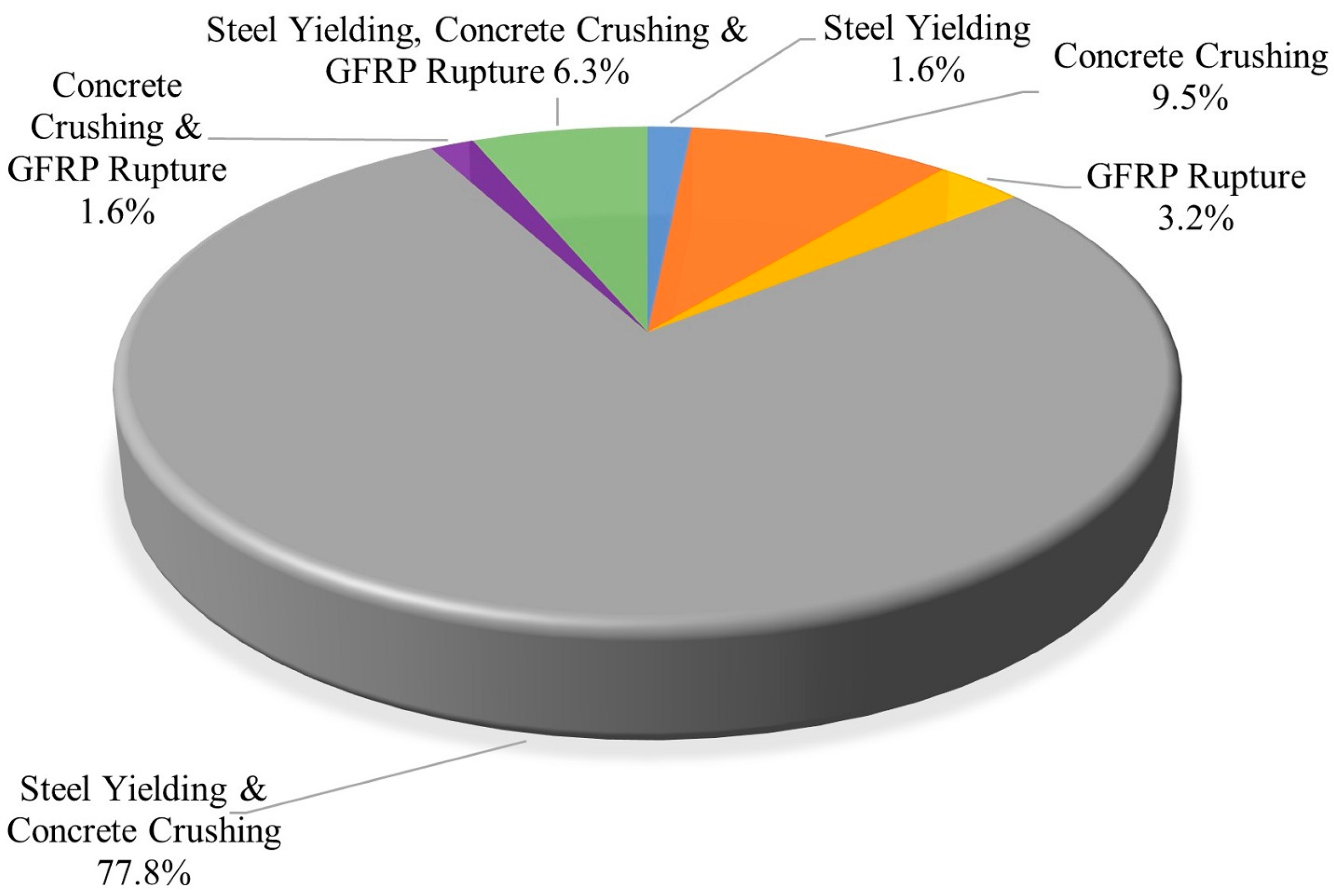
- Most of the flexural beams that experimented with the GFRP–steel hybrid reinforcement system has reported a combined failure mode of steel yielding and concrete crushing. This indicates the activation of the yield behaviour of steel bars before the (rupture) failure of GFRP in the system, which gives the confidence to consider a hybrid reinforcement system for flexure beams.
- In the experimental studies of hybrid GFRP–steel, excessive shear reinforcement has been employed as a strategy to prevent shear failure.
- The attempt to engineer the shear response of hybrid GFRP–steel in RC led to a notable improvement in the performance of flexure-shear failures with a minimal amount of shear cracks and shear crack widths.
- The weakness of GFRPs in RC is in its susceptibility to thermal degradation at comparatively lower temperatures than steel. However, recent studies suggested that this weakness can be mitigated by using adequate concrete cover for increased thermal resistance and applying fire retardants to enhance its performance up to the recommended standard.
- Hybrid GFRP–steel reinforcement is an effective and competitive alternative to steel reinforcement. As identified in this paper, key aspects of their design and structural behaviours must be better understood and require further research to put forward a reliable and sound design procedure.
Author Contributions
Funding
Institutional Review Board Statement
Informed Consent Statement
Data Availability Statement
Conflicts of Interest
References
- Attia, M.M.; Ahmed, O.; Kobesy, O.; Malek, A.S. Behavior of FRP rods under uniaxial tensile strength with multiple materials as an alternative to steel rebar. Case Stud. Constr. Mater. 2022, 17, e01241. [Google Scholar] [CrossRef]
- Looney, T.; Leggs, M.; Volz, J.; Floyd, R. Durability and corrosion resistance of ultra-high performance concretes for repair. Constr. Build. Mater. 2022, 345, 128238. [Google Scholar] [CrossRef]
- Ming, J.; Zhou, X.; Jiang, L.; Shi, J. Corrosion resistance of low-alloy steel in concrete subjected to long-term chloride attack: Characterization of surface conditions and rust layers. Corros. Sci. 2022, 203, 110370. [Google Scholar] [CrossRef]
- Yu, X.; Al-Saadi, S.; Zhao, X.L.; Raman, R.K.S. Electrochemical investigations of steels in seawater sea sand concrete environments. Materials 2021, 14, 5713. [Google Scholar] [CrossRef] [PubMed]
- Melchers, R.E.; Chaves, I.A. Durable steel-reinforced concrete structures for marine environments. Sustainability 2021, 13, 13695. [Google Scholar] [CrossRef]
- Němeček, J.; Trávníček, P.; Němečková, J.; Kruis, J. Mitigation of chloride induced corrosion in reinforced concrete structures and its modeling. Koroze A Ochr. Mater. 2021, 65, 79–85. [Google Scholar] [CrossRef]
- Omer, L.M.; Gomaa, M.S.; Sufe, W.H.; Elsayed, A.A.; Elghazaly, H.A. Enhancing corrosion resistance of RC pipes using geopolymer mixes when subjected to aggressive environment. J. Eng. Appl. Sci. 2022, 69, 3. [Google Scholar] [CrossRef]
- Li, W.; Wu, M.; Shi, T.; Yang, P.; Pan, Z.; Liu, W.; Liu, J.; Yang, X. Experimental Investigation of the Relationship between Surface Crack of Concrete Cover and Corrosion Degree of Steel Bar Using Fractal Theory. Fractal Fract. 2022, 6, 325. [Google Scholar] [CrossRef]
- Li, Q.; Gao, Z.; Yang, T.; Dong, Z.; Jiang, Z.; He, Q.; Fu, C. Rust Distribution of Non-Uniform Steel Corrosion Induced by Impressed Current Method. Materials 2022, 15, 4276. [Google Scholar] [CrossRef]
- Gao, X.X.; Deby, F.; Gourbeyre, Y.; Samson, G.; Garcia, S.; Arliguie, G. Influence of catholytes on the generation of steel corrosion in concrete with accelerated chloride migration method. Case Stud. Constr. Mater. 2022, 16, e01123. [Google Scholar] [CrossRef]
- Schmitt, G. Global needs for knowledge dissemination, research, and development in materials deterioration and corrosion control. World Corros. Organ. 2009, 38, 14. [Google Scholar]
- Mohammed, T.U.; Rahman, M.; Sabbir, A.; Hasan, M.M.; Mamun, A.A. Chloride ingress and macro-cell corrosion of steel in concrete made with recycled brick aggregate. Front. Struct. Civ. Eng. 2021, 15, 1358–1371. [Google Scholar] [CrossRef]
- O’Reilly, M.; Darwin, D.; Browning, J.; Locke, C.E.; Virmani, Y.P.; Ji, J.; Gong, L.; Guo, G.; Draper, J.; Xing, L. Multiple Corrosion Protection Systems for Reinforced Concrete Bridge Components: Field Tests. J. Mater. Civ. Eng. 2021, 33, 04021363. [Google Scholar] [CrossRef]
- Long, Z.; Zhang, R.; Wang, Q.; Xie, C.; Zhang, J.; Duan, Y. Mechanism analysis of strength evolution of concrete structure in saline soil area based on 15-year service. Constr. Build. Mater. 2022, 332, 127281. [Google Scholar] [CrossRef]
- Hassanli, R.; Youssf, O.; Manalo, A.; Najafgholipour, M.A.; Elchalakani, M.; Del Rey Castillo, E.; Lutze, D. An Experimental Study of the Behavior of GFRP-Reinforced Precast Concrete Culverts. J. Compos. Constr. 2022, 26, 04022043. [Google Scholar] [CrossRef]
- Sheikh, S.A.; Kharal, Z. Replacement of steel with GFRP for sustainable reinforced concrete. Constr. Build. Mater. 2018, 160, 767–774. [Google Scholar] [CrossRef]
- Jabbar, S.A.; Farid, S.B. Replacement of steel rebars by GFRP rebars in the concrete structures. Karbala Int. J. Mod. Sci. 2018, 4, 216–227. [Google Scholar] [CrossRef]
- El-Sayed, T.A.; Erfan, A.M.; Abdelnaby, R.M.; Soliman, M.K. Flexural behavior of HSC beams reinforced by hybrid GFRP bars with steel wires. Case Stud. Constr. Mater. 2022, 16, e01054. [Google Scholar] [CrossRef]
- Karim, R.; Shafei, B. Performance of fiber-reinforced concrete link slabs with embedded steel and GFRP rebars. Eng. Struct. 2021, 229, 111590. [Google Scholar] [CrossRef]
- Ramanathan, S.; Benzecry, V.; Suraneni, P.; Nanni, A. Condition assessment of concrete and glass fiber reinforced polymer (GFRP) rebar after 18 years of service life. Case Stud. Constr. Mater. 2021, 14, e00494. [Google Scholar] [CrossRef]
- Li, W.; Wen, F.; Zhou, M.; Liu, F.; Jiao, Y.; Wu, Q.; Liu, H. Assessment and Prediction Model of GFRP Bars’ Durability Performance in Seawater Environment. Buildings 2022, 12, 127. [Google Scholar] [CrossRef]
- Wu, W.; He, X.; Yang, W.; Dai, L.; Wang, Y.; He, J. Long-time durability of GFRP bars in the alkaline concrete environment for eight years. Constr. Build. Mater. 2022, 314, 125573. [Google Scholar] [CrossRef]
- Xingyu, G.; Yiqing, D.; Jiwang, J. Flexural behavior investigation of steel-GFRP hybrid-reinforced concrete beams based on experimental and numerical methods. Eng. Struct. 2020, 206, 110117. [Google Scholar] [CrossRef]
- Acciai, A.; D’Ambrisi, A.; De Stefano, M.; Feo, L.; Focacci, F.; Nudo, R. Experimental response of FRP reinforced members without transverse reinforcement: Failure modes and design issues. Compos. Part B Eng. 2016, 89, 397–407. [Google Scholar] [CrossRef]
- Li, L.; Lu, J.; Fang, S.; Liu, F.; Li, S. Flexural study of concrete beams with basalt fibre polymer bars. Proc. Inst. Civ. Eng.-Struct. Build. 2018, 171, 505–516. [Google Scholar] [CrossRef]
- Yoo, D.-Y.; Moon, D.-Y. Effect of steel fibers on the flexural behavior of RC beams with very low reinforcement ratios. Constr. Build. Mater. 2018, 188, 237–254. [Google Scholar] [CrossRef]
- Qin, F.; Zhang, Z.; Yin, Z.; Di, J.; Xu, L.; Xu, X. Use of high strength, high ductility engineered cementitious composites (ECC) to enhance the flexural performance of reinforced concrete beams. J. Build. Eng. 2020, 32, 101746. [Google Scholar] [CrossRef]
- Deng, M.; Zhang, M.; Zhu, Z.; Ma, F. Deformation capacity of over-reinforced concrete beams strengthened with highly ductile fiber-reinforced concrete. In Structures; Elsevier: Amsterdam, The Netherlands, 2021; pp. 1861–1873. [Google Scholar]
- Abbas, H.; Abadel, A.; Almusallam, T.; Al-Salloum, Y. Experimental and analytical study of flexural performance of concrete beams reinforced with hybrid of GFRP and steel rebars. Eng. Fail. Anal. 2022, 138, 106397. [Google Scholar] [CrossRef]
- Yuan, J.; Gao, D.; Zhang, Y.; Zhu, H. Improving Ductility for Composite Beams Reinforced with GFRP Tubes by Using Rebars/Steel Angles. Polymers 2022, 14, 551. [Google Scholar] [CrossRef]
- Xu, J.; Zhu, P.; Qu, W. Numerical and Analytical Study of Concrete Beams Reinforced with Hybrid Fiber-Reinforced Polymer and Steel Bars. J. Compos. Constr. 2022, 26, 04022045. [Google Scholar] [CrossRef]
- Han, S.; Fan, C.; Zhou, A.; Ou, J. Simplified implementation of equivalent and ductile performance for steel-FRP composite bars reinforced seawater sea-sand concrete beams: Equal-stiffness design method. Eng. Struct. 2022, 266, 114590. [Google Scholar] [CrossRef]
- Thamrin, R.; Zaidir, Z.; Iwanda, D. Ductility Estimation for Flexural Concrete Beams Longitudinally Reinforced with Hybrid FRP–Steel Bars. Polymers 2022, 14, 1017. [Google Scholar] [CrossRef] [PubMed]
- Nguyen, P.D.; Dang, V.H.; Vu, N.A. Performance of concrete beams reinforced with various ratios of hybrid GFRP/steel bars. Civ. Eng. J. 2020, 6, 1652–1669. [Google Scholar] [CrossRef]
- Moolaei, S.; Sharbatdar, M.K.; Kheyroddin, A. Experimental evaluation of flexural behavior of HPFRCC beams reinforced with hybrid steel and GFRP bars. Compos. Struct. 2021, 275, 114503. [Google Scholar] [CrossRef]
- Li, Z.; Khennane, A.; Hazell, P.J.; Remennikov, A.M. Performance of a hybrid GFRP-concrete beam subject to low-velocity impacts. Compos. Struct. 2018, 206, 425–438. [Google Scholar] [CrossRef]
- Sijavandi, K.; Sharbatdar, M.K.; Kheyroddin, A. Experimental evaluation of flexural behavior of high-performance fiber reinforced concrete beams using GFRP and high strength steel bars. In Structures; Elsevier: Amsterdam, The Netherlands, 2021; pp. 4256–4268. [Google Scholar]
- Xiao, S.-H.; Lin, J.-X.; Li, L.-J.; Guo, Y.-C.; Zeng, J.-J.; Xie, Z.-H.; Wei, F.-F.; Li, M. Experimental study on flexural behavior of concrete beam reinforced with GFRP and steel-fiber composite bars. J. Build. Eng. 2021, 43, 103087. [Google Scholar] [CrossRef]
- Qu, W.; Zhang, X.; Huang, H. Flexural behavior of concrete beams reinforced with hybrid (GFRP and steel) bars. J. Compos. Constr. 2009, 13, 350–359. [Google Scholar] [CrossRef]
- Liu, Y.H.; Yuan, Y. Experimental Studies on High Strength Concrete Beams Reinforced with Steel and GFRP Rebars. In Applied Mechanics and Materials; Trans Tech Publications Ltd.: Bäch, Switzerland, 2012; pp. 669–673. [Google Scholar]
- Safan, M.A. Flexural Behavior and Design of Steel-GFRP Reinforced Concrete Beams. ACI Mater. J. 2013, 110, 667. [Google Scholar]
- Qin, R.; Zhou, A.; Lau, D. Effect of reinforcement ratio on the flexural performance of hybrid FRP reinforced concrete beams. Compos. Part B Eng. 2017, 108, 200–209. [Google Scholar] [CrossRef]
- Yoo, D.-Y.; Banthia, N.; Yoon, Y.-S. Flexural behavior of ultra-high-performance fiber-reinforced concrete beams reinforced with GFRP and steel rebars. Eng. Struct. 2016, 111, 246–262. [Google Scholar] [CrossRef]
- Behera, P.K.; Misra, S.; Mondal, K. Corrosion of Strained Plain Rebar in Chloride-Contaminated Mortar and Novel Approach to Estimate the Corrosion Amount from Rust Characterization. J. Mater. Civ. Eng. 2021, 33, 04021283. [Google Scholar] [CrossRef]
- Ding, Q.; Gao, Y.; Hou, W.; Qin, Y. Influence of Cl- concentration on corrosion behavior of reinforced concrete in soil. J. Chin. Soc. Corros. Prot. 2021, 41, 705–711. [Google Scholar] [CrossRef]
- Ding, Q.; Gao, Y.; Liu, R.; Li, Y.; Jin, L.; Ma, H. Corrosion behavior of HRB400 and HRB400M steel bars in concrete under DC interference. Sci. Rep. 2021, 11, 23871. [Google Scholar] [CrossRef] [PubMed]
- Franco-Luján, V.A.; Maldonado-García, M.A.; Mendoza-Rangel, J.M.; Montes-García, P. Effect of Cl−-induced corrosion on the mechanical properties of reinforcing steel embedded in ternary concretes containing FA and UtSCBA. Constr. Build. Mater. 2022, 339, 127655. [Google Scholar] [CrossRef]
- Alexander, M.; Beushausen, H. Durability, service life prediction, and modelling for reinforced concrete structures–review and critique. Cem. Concr. Res. 2019, 122, 17–29. [Google Scholar] [CrossRef]
- Afshar, A.; Shokrgozar, A.; Afshar, A.; Afshar, A. Simulation of corrosion protection methods in reinforced concrete by artificial neural networks and fuzzy logic. J. Electrochem. Sci. Eng. 2022, 12, 511–527. [Google Scholar] [CrossRef]
- Bastidas, D.M.; Martin, U.; Bastidas, J.M.; Ress, J. Corrosion inhibition mechanism of steel reinforcements in mortar using soluble phosphates: A critical review. Materials 2021, 14, 6168. [Google Scholar] [CrossRef]
- El Alami, E.; Fekak, F.E.; Garibaldi, L.; Elkhalfi, A. A numerical study of pitting corrosion in reinforced concrete structures. J. Build. Eng. 2021, 43, 102789. [Google Scholar] [CrossRef]
- Fan, L.; Teng, L.; Tang, F.; Khayat, K.H.; Chen, G.; Meng, W. Corrosion of steel rebar embedded in UHPC beams with cracked matrix. Constr. Build. Mater. 2021, 313, 125589. [Google Scholar] [CrossRef]
- Ge, W.J.; Zhu, J.W.; Ashour, A.; Yang, Z.P.; Cai, X.N.; Yao, S.; Yan, W.H.; Cao, D.F.; Lu, W.G. Effect of Chloride Corrosion on Eccentric-Compression Response of Concrete Columns Reinforced with Steel-FRP Composite Bars. J. Compos. Constr. 2022, 26, 04022042. [Google Scholar] [CrossRef]
- Jee, A.A.; Pradhan, B. Long term effect of chloride and sulfates concentration, and cation allied with sulfates on corrosion performance of steel-reinforced in concrete. J. Build. Eng. 2022, 56, 104813. [Google Scholar] [CrossRef]
- Graham-Jones, J.; Summerscales, J. Marine Applications of Advanced Fibre-Reinforced Composites; Woodhead Publishing: Sawston, UK, 2015. [Google Scholar]
- Kim, Y.J. State of the practice of FRP composites in highway bridges. Eng. Struct. 2019, 179, 1–8. [Google Scholar] [CrossRef]
- Noël, M. Probabilistic fatigue life modelling of FRP composites for construction. Constr. Build. Mater. 2019, 206, 279–286. [Google Scholar] [CrossRef]
- Ferdous, W.; Manalo, A.; Sharda, A.; Bai, Y.; Ngo, T.D.; Mendis, P. Construction Industry Transformation through Modular Methods. In Innovation in Construction; Springer: Berlin/Heidelberg, Germany, 2022; pp. 259–276. [Google Scholar]
- Li, C.; Zhu, H.; Niu, G.; Cheng, S.; Gu, Z.; Yang, L. Flexural behavior and a new model for flexural design of concrete beams hybridly reinforced by continuous FRP bars and discrete steel fibers. In Structures; Elsevier: Amsterdam, The Netherlands, 2022; pp. 949–960. [Google Scholar]
- Davids, W.G.; Diba, A.; Dagher, H.J.; Guzzi, D.; Schanck, A.P. Development, assessment and implementation of a novel FRP composite girder bridge. Constr. Build. Mater. 2022, 340, 127818. [Google Scholar] [CrossRef]
- Shin, J.; Park, S. Optimum retrofit strategy of FRP column jacketing system for non-ductile RC building frames using artificial neural network and genetic algorithm hybrid approach. J. Build. Eng. 2022, 57, 104919. [Google Scholar] [CrossRef]
- George, J.M.; Kimiaei, M.; Elchalakani, M.; Efthymiou, M. Flexural response of underwater offshore structural members retrofitted with CFRP wraps and their performance after exposure to real marine conditions. In Structures; Elsevier: Amsterdam, The Netherlands, 2022; pp. 559–573. [Google Scholar]
- Zhou, S.; Demartino, C.; Xu, J.; Xiao, Y. Effectiveness of CFRP seismic-retrofit of circular RC bridge piers under vehicular lateral impact loading. Eng. Struct. 2021, 243, 112602. [Google Scholar] [CrossRef]
- Burgoyne, C.; Byars, E.; Guadagnini, M.; Manfredi, G.; Neocleous, K.; Pilakoutas, K.; Taerwe, L.; Taranu, N.; Tepfers, R.; Weber, A. FRP Reinforcement in RC Structures; FIB (International Federation for Structural Concrete): Losanna, Switzerland, 2007. [Google Scholar]
- Coricciati, A.; Corvaglia, P.; Mosheyev, G. Durability of fibers in aggressive alkaline environment. In Proceedings of the 17th International Conference on Composite Materials-ICCM-17, Edinburgh, Scotland, UK, 27–31 July 2009. [Google Scholar]
- Abbood, I.S.; aldeen Odaa, S.; Hasan, K.F.; Jasim, M.A.J. Properties evaluation of fiber reinforced polymers and their constituent materials used in structures—A review. Mater. Today Proc. 2021, 43, 1003–1008. [Google Scholar] [CrossRef]
- Gooranorimi, O.; Nanni, A. GFRP reinforcement in concrete after 15 years of service. J. Compos. Constr. 2017, 21, 04017024. [Google Scholar] [CrossRef]
- Gauvin, F.; Robert, M. Durability study of vinylester/silicate nanocomposites for civil engineering applications. Polym. Degrad. Stab. 2015, 121, 359–368. [Google Scholar] [CrossRef]
- Bonsu, A.O.; Liang, W.; Mensah, C.; Yang, B. Assessing the mechanical behavior of glass and basalt reinforced vinyl ester composite under artificial seawater environment. In Structures; Elsevier: Amsterdam, The Netherlands, 2022; pp. 961–978. [Google Scholar]
- Mukhtar, F.M.; Arowojolu, O. Recent developments in experimental and computational studies of hygrothermal effects on the bond between FRP and concrete. J. Reinf. Plast. Compos. 2020, 39, 422–442. [Google Scholar] [CrossRef]
- Wang, P.; Wu, H.-L.; Leung, C.K. Mechanical and long-term durability prediction of GFRP rebars with the adoption of low-pH CSA concrete. Constr. Build. Mater. 2022, 346, 128444. [Google Scholar] [CrossRef]
- Li, C.; Guo, R.; Xian, G.; Li, H. Effects of elevated temperature, hydraulic pressure and fatigue loading on the property evolution of a carbon/glass fiber hybrid rod. Polym. Test. 2020, 90, 106761. [Google Scholar] [CrossRef]
- Lal, H.M.; Uthaman, A.; Li, C.; Xian, G.; Thomas, S. Combined effects of cyclic/sustained bending loading and water immersion on the interface shear strength of carbon/glass fiber reinforced polymer hybrid rods for bridge cable. Constr. Build. Mater. 2022, 314, 125587. [Google Scholar] [CrossRef]
- Barcikowski, M.; Lesiuk, G.; Czechowski, K.; Duda, S. Static and flexural fatigue behavior of GFRP pultruded rebars. Materials 2021, 14, 297. [Google Scholar] [CrossRef]
- Oskouei, A.V.; Bazli, M.; Ashrafi, H.; Imani, M. Flexural and web crippling properties of GFRP pultruded profiles subjected to wetting and drying cycles in different sea water conditions. Polym. Test. 2018, 69, 417–430. [Google Scholar] [CrossRef]
- Wang, Z.; Zhao, X.-L.; Xian, G.; Wu, G.; Raman, R.S.; Al-Saadi, S. Effect of sustained load and seawater and sea sand concrete environment on durability of basalt-and glass-fibre reinforced polymer (B/GFRP) bars. Corros. Sci. 2018, 138, 200–218. [Google Scholar] [CrossRef]
- Deitz, D.; Harik, I.; Gesund, H. Physical properties of glass fiber reinforced polymer rebars in compression. J. Compos. Constr. 2003, 7, 363–366. [Google Scholar] [CrossRef]
- Choi, E.; Utui, N.; Kim, H.S. Experimental and analytical investigations on debonding of hybrid FRPs for flexural strengthening of RC beams. Compos. Part B Eng. 2013, 45, 248–256. [Google Scholar] [CrossRef]
- Alraie, A.; Garg, N.; Matsagar, V.; Goldack, A.; Schlaich, M. Pseudo-Ductility through Progressive Failure of Multi-Layered Carbon-Fiber-Reinforced Polymer (CFRP) Prestressed Concrete Beams. Struct. Eng. Int. 2022, 1–16. [Google Scholar] [CrossRef]
- Askar, M.K.; Hassan, A.F.; Al-Kamaki, Y.S. Flexural and Shear Strengthening of Reinforced Concrete Beams Using FRP Composites: A State of The Art. Case Stud. Constr. Mater. 2022, 17, e01189. [Google Scholar] [CrossRef]
- Harris, H.G.; Somboonsong, W.; Ko, F.K. New ductile hybrid FRP reinforcing bar for concrete structures. J. Compos. Constr. 1998, 2, 28–37. [Google Scholar] [CrossRef]
- Issa, M.S.; Metwally, I.M.; Elzeiny, S.M. Influence of fibers on flexural behavior and ductility of concrete beams reinforced with GFRP rebars. Eng. Struct. 2011, 33, 1754–1763. [Google Scholar] [CrossRef]
- Lau, D.; Pam, H.J. Experimental study of hybrid FRP reinforced concrete beams. Eng. Struct. 2010, 32, 3857–3865. [Google Scholar] [CrossRef]
- Salleh, N.; Hamid, N.A.; Majid, M.A. Finite element modelling of concrete beams reinforced with hybrid fiber reinforced bars. In Proceedings of the Materials Science and Engineering Conference Series, Birmingham, UK, 13–15 October 2017; p. 012093. [Google Scholar]
- Araba, A.M.; Ashour, A.F. Flexural performance of hybrid GFRP-Steel reinforced concrete continuous beams. Compos. Part B Eng. 2018, 154, 321–336. [Google Scholar] [CrossRef]
- Maranan, G.; Manalo, A.; Benmokrane, B.; Karunasena, W.; Mendis, P.; Nguyen, T. Flexural behavior of geopolymer-concrete beams longitudinally reinforced with GFRP and steel hybrid reinforcements. Eng. Struct. 2019, 182, 141–152. [Google Scholar] [CrossRef]
- Ruan, X.; Lu, C.; Xu, K.; Xuan, G.; Ni, M. Flexural behavior and serviceability of concrete beams hybrid-reinforced with GFRP bars and steel bars. Compos. Struct. 2020, 235, 111772. [Google Scholar] [CrossRef]
- American Concrete Institute (ACI). Guide for the Design and Construction of Structural Concrete Reinforced with Fiber Reinforced Polymer (FRP) Bars. 440.1 R-15; American Concrete Institute: Farmington Hills, MI, USA, 2015. [Google Scholar]
- Ge, W.; Wang, Y.; Ashour, A.; Lu, W.; Cao, D. Flexural performance of concrete beams reinforced with steel–FRP composite bars. Arch. Civ. Mech. Eng. 2020, 20, 1–17. [Google Scholar] [CrossRef]
- Zhou, Y.; Wu, Y.; Teng, J.; Leung, A. Ductility analysis of compression-yielding FRP-reinforced composite beams. Cem. Concr. Compos. 2009, 31, 682–691. [Google Scholar] [CrossRef]
- Oudah, F.; El-Hacha, R. Ductility of FRP reinforced RC structures: A critical review of definition and expressions. Concr. Solut. 2014, 2014, 329–335. [Google Scholar]
- Bui, L.V.H.; Stitmannaithum, B.; Ueda, T. Ductility of concrete beams reinforced with both fiber-reinforced Polymer and steel tension bars. J. Adv. Concr. Technol. 2018, 16, 531–548. [Google Scholar] [CrossRef]
- Newhook, J. Design of under-reinforced concrete T-sections with GFRP reinforcement. In Proc., 3rd Int. Conf. on Advanced Composite Materials in Bridges and Structures; Canadian Society for Civil Engineering: Montreal, QC, Canada, 2000; pp. 153–160. [Google Scholar]
- Aiello, M.A.; Ombres, L. Structural performances of concrete beams with hybrid (fiber-reinforced polymer-steel) reinforcements. J. Compos. Constr. 2002, 6, 133–140. [Google Scholar] [CrossRef]
- Ge, W.; Zhang, J.; Cao, D.; Tu, Y. Flexural behaviors of hybrid concrete beams reinforced with BFRP bars and steel bars. Constr. Build. Mater. 2015, 87, 28–37. [Google Scholar] [CrossRef]
- Grace, N.F.; Soliman, A.; Abdel-Sayed, G.; Saleh, K. Behavior and ductility of simple and continuous FRP reinforced beams. J. Compos. Constr. 1998, 2, 186–194. [Google Scholar] [CrossRef]
- Naaman, A.; Jeong, S. Structural Ductility of Concrete Beams Prestressed with FRP Tendons. In Non-Metallic (FRP) Reinforcement for Concrete Structures: Proceedings of the Second International RILEM Symposium; CRC Press: Boca Raton, FL, USA, 1995; p. 379. [Google Scholar]
- Abdelrahman, A.; Tadros, G.; Rizkalla, S. Test model for first canadian smart highway bridge. ACI Struct. J. 1995, 92, 451–458. [Google Scholar]
- Zou, P.X. Flexural behavior and deformability of fiber reinforced polymer prestressed concrete beams. J. Compos. Constr. 2003, 7, 275–284. [Google Scholar] [CrossRef]
- Shin, S.; Seo, D.; Han, B. Performance of concrete beams reinforced with GFRP bars. J. Asian Archit. Build. Eng. 2009, 8, 197–204. [Google Scholar] [CrossRef]
- Pang, L.; Qu, W.; Zhu, P.; Xu, J. Design propositions for hybrid FRP-steel reinforced concrete beams. J. Compos. Constr. 2016, 20, 04015086. [Google Scholar] [CrossRef]
- El Zareef, M.A.; El Madawy, M.E. Effect of glass-fiber rods on the ductile behaviour of reinforced concrete beams. Alex. Eng. J. 2018, 57, 4071–4079. [Google Scholar] [CrossRef]
- Abdelrahman, A.A.; Rizkalla, S.H. Serviceability of concrete beams prestressed by carbon. ACI Struct. J. 1997, 94, 447–454. [Google Scholar]
- Mufti, A.A.; Newhook, J.P.; Tadros, G. Deformability versus ductility in concrete beams with FRP reinforcement. In Proceedings of the 2nd International Conference on Advanced Composite Materials in Bridge and Structures, Montreal, QC, Canada, 11–14 August 1996. [Google Scholar]
- Bakht, B.; Al-Bazi, G.; Banthia, N.; Cheung, M.; Erki, M.-A.; Faoro, M.; Machida, A.; Mufti, A.A.; Neale, K.W.; Tadros, G. Canadian bridge design code provisions for fiber-reinforced structures. J. Compos. Constr. 2000, 4, 3–15. [Google Scholar] [CrossRef]
- BC Ministry of Transportation and Infrastructure. Volume 1-Supplement to CHBDC S6-14; BC Ministry of Transportation and Infrastructure: Coquitlam, BC, Canada, 2016.
- Allam, S.M.; Shoukry, M.S.; Rashad, G.E.; Hassan, A.S. Crack width evaluation for flexural RC members. Alex. Eng. J. 2012, 51, 211–220. [Google Scholar] [CrossRef]
- JSCE. Application of Continuous Fiber Reinforcing Materials to Concrete Structures; JSCE (Japan Society of Civil Engineers): Tokyo, Japan, 1992. [Google Scholar]
- Nanni, A. Guide for the design and construction of concrete reinforced with FRP bars (ACI 440.1 R-03). In Structures Congress 2005: Metropolis and Beyond; American Society of Civil Engineers (ASCE): Reston, VA, USA, 2005; pp. 1–6. [Google Scholar]
- AASHTO-LRFD. Bridge Design Specifications, 2nd ed.; American Association of State Highway Transportation Officials: Washington, DC, USA, 2018. [Google Scholar]
- El Refai, A.; Abed, F.; Al-Rahmani, A. Structural performance and serviceability of concrete beams reinforced with hybrid (GFRP and steel) bars. Constr. Build. Mater. 2015, 96, 518–529. [Google Scholar] [CrossRef]
- Nanni, A.; De Luca, A.; Zadeh, H. Reinforced Concrete with FRP Bars; CRC Press: Boca Raton, FL, USA, 2014; ISBN 978-0-203-87429-5. [Google Scholar]
- ACI-440; Guide for the Design and Construction of structural concrete reinforced with FRP bars (ACI 440.1 R-01). American Concrete Institute: Farmington Hills, MI, USA, 2001.
- van Zijl, G.; Mbewe, P. Flexural modelling of steel fibre-reinforced concrete beams with and without steel bars. Eng. Struct. 2013, 53, 52–62. [Google Scholar] [CrossRef]
- Leung, H.Y.; Balendran, R. Flexural behaviour of concrete beams internally reinforced with GFRP rods and steel rebars. Struct. Surv. 2003, 21, 146–157. [Google Scholar] [CrossRef]
- American Concrete Institute. Guide for the Design and Construction of Structural Concrete Reinforced with FRP Bars. 440.1 R-06; American Concrete Institute: Farmington Hills, MI, USA, 2006. [Google Scholar]
- CNR-DT. Guide for the Design and Construction of Concrete Structures Reinforced with Fiber-Reinforced Polymer Bars; National Research Council: Rome, Italy, 2006; Volume 203. [Google Scholar]
- Rizkalla, S.H.; Aftab, A.M.; ISIS. Reinforcing Concrete Structures with Fibre Reinforced Polymers; ISIS Canada Research Network: Winnipeg, MB, Canada, 2001. [Google Scholar]
- JSCE. Recommendations for Design and Construction of Concrete Structures Using Continuous Fibre Reinforced Materials; Japan Society of Civil Engineers: Tokyo, Japan, 1997; Volume 23. [Google Scholar]
- Arabzadeh, A.; Rahaie, A.; Aghayari, R. A Simple Strut-and-Tie Model for Prediction of Ultimate Shear Strength of RC Deep Beams. Int. J. Civ. Eng. 2009, 7, 141–153. [Google Scholar]
- Rasheed, M.M. Modified Softened Strut and Tie Model for Concrete Deep Beams. J. Eng. Sustain. Dev. 2012, 16, 348–361. [Google Scholar]
- Nehdi, M.; El Chabib, H.; Saïd, A.A. Proposed shear design equations for FRP-reinforced concrete beams based on genetic algorithms approach. J. Mater. Civ. Eng. 2007, 19, 1033–1042. [Google Scholar] [CrossRef]
- Vo-Le, D.; Tran, D.T.; Pham, T.M.; Ho-Huu, C.; Nguyen-Minh, L. Re-evaluation of shear contribution of CFRP and GFRP sheets in concrete beams post-tensioned with unbonded tendons. Eng. Struct. 2022, 259, 114173. [Google Scholar] [CrossRef]
- Campana, S.; Fernández Ruiz, M.; Anastasi, A.; Muttoni, A. Analysis of shear-transfer actions on one-way RC members based on measured cracking pattern and failure kinematics. Mag. Concr. Res. 2013, 65, 386–404. [Google Scholar] [CrossRef]
- Zilch, K.; Niedermeier, R.; Finckh, W. Strengthening of Concrete Structures with ADHESIVELY Bonded Reinforcement: Design and Dimensioning of CFRP Laminates and Steel Plates; John Wiley & Sons: Hoboken, NJ, USA, 2014. [Google Scholar]
- Ayoubinejad, J.; Marashi, M. Investigation of fatigue phenomena and stress variations by using FRP dowel bars. J. Struct. Constr. Eng. 2022, 8, 144–155. [Google Scholar]
- Szczech, D.; Kotynia, R. Effect of shear reinforcement ratio on the shear capacity of GFRP reinforced concrete beams. Arch. Civ. Eng. 2021, 67, 425–437. [Google Scholar]
- Shehata, E.F. Fibre-Reinforced Polymer (FRP) for Shear Reinforcement in Concrete Structures; University of Manitoba: Winnipeg, MB, Canada, 1999. [Google Scholar]
- Nasrollahzadeh, K.; Aghamohammadi, R. Reliability analysis of shear strength provisions for FRP-reinforced concrete beams. Eng. Struct. 2018, 176, 785–800. [Google Scholar] [CrossRef]
- Choi, K.-K.; Hong-Gun, P.; Wight, J.K. Unified shear strength model for reinforced concrete beams-Part I: Development. ACI Struct. J. 2007, 104, 142. [Google Scholar]
- Oller, E.; Marí, A.; Bairán, J.M.; Cladera, A. Shear design of reinforced concrete beams with FRP longitudinal and transverse reinforcement. Compos. Part B Eng. 2015, 74, 104–122. [Google Scholar] [CrossRef]
- Pilakoutas, K.; Guadagnini, M. Shear of FRP RC: A review of the state-of-the-art. In Composites in Construction: A Reality; American Society of Civil Engineers: Capri, Italy, 2001; pp. 173–182. [Google Scholar]
- IStructE. Interim Guidance on the Design of Reinforced Concrete Structures Using Fibre Composite Reinforcement; Institution of Structural Engineers: London, UK, 1999. [Google Scholar]
- CSA. Design of Concrete Structures; CSA: Toronto, ON, Canada, 2004; Volume A23. [Google Scholar]
- Taerwe, L.; Matthys, S.; Pilakoutas, K.; Guadagnini, M. European Activities on the Use of FRP Reinforcement; Thomas Telford Publishing: Cambridge, UK, 2001; Volume 1, pp. 3–15. [Google Scholar]
- ICS. Eurocode 2: Design of Concrete Structures: Part 1-1: General Rules and Rules for Buildings; National Standards Authority of Ireland: Dublin, Ireland, 2004. [Google Scholar]
- BSI. Structural Use of Concrete—Design and Construction; 8110-1; BSI: London, UK, 1997. [Google Scholar]
- American Concrete Institute. Building Code Requirements for Structural Concrete (ACI 318-05) and Commentary (ACI 318R-05); American Concrete Institute: Farmington Hills, MI, USA, 2005. [Google Scholar]
- Lie, T.; Kodur, V. Fire resistance of steel columns filled with bar-reinforced concrete. J. Struct. Eng. 1996, 122, 30–36. [Google Scholar] [CrossRef]
- Le, Q.X.; Dao, V.T.; Torero, J.L.; Maluk, C.; Bisby, L. Effects of temperature and temperature gradient on concrete performance at elevated temperatures. Adv. Struct. Eng. 2018, 21, 1223–1233. [Google Scholar] [CrossRef]
- de Oliveira, A.M.; Oliveira, A.P.; Vieira, J.D.; Junior, A.N.; Cascudo, O. Study of the development of hydration of ternary cement pastes using X-ray computed microtomography, XRD-Rietveld method, TG/DTG, DSC, calorimetry and FTIR techniques. J. Build. Eng. 2022, 64, 105616. [Google Scholar] [CrossRef]
- Naus, D.J. The Effect of Elevated Temperature on Concrete Materials and Structures—A Literature Review; Oak Ridge National Laboratory: Oak Ridge, TN, USA, 2006. [Google Scholar]
- Bilow, D.N.; Kamara, M.E. Fire and Concrete Structures. In Structures Congress 2008: Crossing Borders; American Society of Civil Engineers: Vancouver, BC, Canada, 2008; pp. 1–10. [Google Scholar]
- Jiang, J.; Qi, H.; Lu, Y.; Li, G.-Q.; Chen, W.; Ye, J. A state-of-the-art review on tensile membrane action in reinforced concrete floors exposed to fire. J. Build. Eng. 2022, 45, 103502. [Google Scholar] [CrossRef]
- Buchanan, A.H.; Abu, A.K. Structural Design for Fire Safety; John Wiley & Sons: Hoboken, NJ, USA, 2017. [Google Scholar]
- Hajiloo, H.; Green, M.F.; Noël, M.; Bénichou, N.; Sultan, M. GFRP-Reinforced Concrete Slabs: Fire Resistance and Design Efficiency. J. Compos. Constr. 2019, 23, 04019009. [Google Scholar] [CrossRef]
- ASTM International Standards Organization. Standard Test Methods for Fire Tests of Building Construction and Materials; ASTM International Standards Organization: West Conshohocken, PA, USA, 2012. [Google Scholar]
- Weber, A.; Witt, C.; Nadjai, A. Composite rebars in RC members in case of fire. In Proc., Advanced Composite Materials in Bridges and Structures; Canadian Society of Civil Engineering: Winnipeg, MB, Canada, 2008. [Google Scholar]
- Karakurt, C. Properties of reinforced concrete steel rebars exposed to high temperatures. Adv. Mater. Sci. Eng. 2008, 2008, 814137. [Google Scholar]
- Raj, H.; Saraf, A.; Sangal, S.; Misra, S. Residual properties of TMT steel bars after exposure to elevated temperatures. J. Mater. Civ. Eng. 2016, 28, 04015098. [Google Scholar] [CrossRef]
- Kodur, V.; ASCE, M.; Bisby, L. Evaluation of Fire Endurance of Concrete Slabs Reinforcedwith Fiber-Reinforced Polymer Bars. J. Struct. Eng. 2005, 131, 34–43. [Google Scholar] [CrossRef]
- Robert, M.; Benmokrane, B. Behavior of GFRP reinforcing bars subjected to extreme temperatures. J. Compos. Constr. 2010, 14, 353–360. [Google Scholar] [CrossRef]
- Li, C.; Xian, G. Experimental and modeling study of the evolution of mechanical properties of PAN-based carbon fibers at elevated temperatures. Materials 2019, 12, 724. [Google Scholar] [CrossRef] [PubMed]
- Feng, G.; Zhu, D.; Guo, S.; Rahman, M.Z.; Jin, Z.; Shi, C. A review on mechanical properties and deterioration mechanisms of FRP bars under severe environmental and loading conditions. Cem. Concr. Compos. 2022, 134, 104758. [Google Scholar] [CrossRef]
- Khaneghahi, M.H.; Najafabadi, E.P.; Shoaei, P.; Oskouei, A.V. Effect of intumescent paint coating on mechanical properties of FRP bars at elevated temperature. Polym. Test. 2018, 71, 72–86. [Google Scholar] [CrossRef]
- Benson, C.M.; Elsmore, S. Reducing fire risk in buildings: The role of fire safety expertise and governance in building and planning approval. J. Hous. Built Environ. 2022, 37, 927–950. [Google Scholar] [CrossRef]
- Saafi, M. Effect of fire on FRP reinforced concrete members. Compos. Struct. 2002, 58, 11–20. [Google Scholar] [CrossRef]
- Abbasi, A.; Hogg, P.J. Fire Testing of Concrete Beams with Fibre Reinforced Plastic Rebar; Elsevier: Amsterdam, The Netherlands, 2004; pp. 445–456. [Google Scholar]
- Nadjai, A.; Talamona, D.; Ali, F. Fire performance of concrete beams reinforced with FRP bars. Proc. Int. Sympsium Bond Behav. FRP Struct. 2005, 401–410. [Google Scholar] [CrossRef]
- Sadek, A.W.; El-Hawary, M.; El-Deeb, A.S. Fire resistance testing of concrete beams reinforced by GFRP rebars. J. Appl. Fire Sci. 2006, 14, 91. [Google Scholar] [CrossRef]
- Rafi, M.; Nadjai, A.; Ali, F.; O’Hare, P. Evaluation of thermal resistance of FRP reinforced concrete beams in fire. J. Struct. Fire Eng. 2011, 2, 91–107. [Google Scholar] [CrossRef]
- Lin, X.; Zhang, Y. Nonlinear finite element analyses of steel/FRP-reinforced concrete beams in fire conditions. Compos. Struct. 2013, 97, 277–285. [Google Scholar] [CrossRef]
- Hawileh, R.; Naser, M. Thermal-stress analysis of RC beams reinforced with GFRP bars. Compos. Part B Eng. 2012, 43, 2135–2142. [Google Scholar] [CrossRef]
- Carvelli, V.; Pisani, M.A.; Poggi, C. High temperature effects on concrete members reinforced with GFRP rebars. Compos. Part B Eng. 2013, 54, 125–132. [Google Scholar] [CrossRef]


| Tensile Strength (MPa) | Compressive Strength (MPa) | Young’s Modulus (GPa) | Advantages | Disadvantages | |
|---|---|---|---|---|---|
| GFRP | 600–1100 | 100–400 | 45–80 | - High tensile strength compared to steel reinforcement - Corrosion resistance - Can be easily cut and shape - Low cost - Can be used in wet and dry conditions - Non-conductive | -Lower strength compared to CFRP and BFRP |
| CFRP | 1500–4000 | 600–200 | 120–400 | -Very high tensile strength -High strength-to-weight ratio -Corrosion resistant -Good fatigue resistance -Non-conductive | -Higher cost compared to GFRP |
| BFRP | 1000–3000 | 400–1500 | 70–200 | -High tensile strength -High strength-to-weight ratio -Corrosion resistant -Non-conductive | -Lower availability and higher cost compared to GFRP -Potential for delamination |
| Source | Beam ID | Reinforcement Content | Reinforcement Type | Ultimate Moment (kNm) | Ultimate Load (kN) | Analytical Model Referenced | Failure Mode | ||||||
|---|---|---|---|---|---|---|---|---|---|---|---|---|---|
| % | Combined (ρ) | Under | Over | Balanced | Experimental | Theoretical | Experimental | Theoretical | |||||
| ρeff | ρeff.b | ||||||||||||
| [39] | B1 | 1.14 | 3.23 | ✓ | 107.9 | 108.9 | ACI 440 | SY, CC | |||||
| B2 | 0.29 | - | ✓ | 146.3 | 136.9 | CC | |||||||
| B3 | 0.71 | 3.45 | ✓ | 127.6 | 134.8 | SY, CC | |||||||
| B4 | 0.71 | 3.73 | ✓ | 132.2 | 145.4 | SY, CC | |||||||
| B5 | 1.08 | 3.88 | ✓ | 121.2 | 131.3 | SY, CC | |||||||
| B6 | 1.16 | 3.88 | ✓ | 141.9 | 155.1 | SY, CC | |||||||
| B7 | 0.35 | 4.08 | ✓ | 78.5 | 83.3 | SY, CC | |||||||
| B8 | 3.49 | 4.41 | ✓ | 211.0 | 272.8 | SY, CC | |||||||
| [83] | MD 1.3 | 1.31 | 4.71 | ✓ | 147.4 | 127.1 | BD 2004 | SY, CC | |||||
| G 0.8 | 0.83 | 0.75 | ✓ | 158.8 | 142.2 | RUP | |||||||
| G 0.3 | 0.89 | 0.85 | ✓ | 147.0 | 143.2 | SY, CC, RUP | |||||||
| MD 2.1 | 2.07 | 5.27 | ✓ | 252.7 | 189.3 | SY, CC | |||||||
| G 2.1 | 2.07 | 0.69 | ✓ | 238.0 | 222.6 | CC, RUP | |||||||
| G 1.0 | 1.71 | 0.81 | ✓ | 261.0 | 216.5 | SY, CC, RUP | |||||||
| G 0.6 | 1.56 | 0.92 | ✓ | 229.0 | 228.2 | SY, CC, RUP | |||||||
| [40] | S1 | 1.2 | 0.7 | ✓ | 72.5 | 81.3 | ACI 440 | CC | |||||
| S2 | 2.64 | 8.56 | ✓ | 69.9 | 80.3 | SY, CC | |||||||
| S3 | 2.64 | 8.56 | ✓ | 74.8 | 80.3 | SY, CC | |||||||
| S4 | 2.64 | 8.56 | ✓ | 82.0 | 80.3 | SY, CC | |||||||
| [41] | B10/8S | n/a | ✓ | 63.0 | 60.8 | BS EN 197-1 | SY, CC | ||||||
| B10/8 | ✓ | 59.6 | 60.8 | SY, CC | |||||||||
| B10/6S | ✓ | 61.6 | 55.4 | SY, CC | |||||||||
| B10/6 | ✓ | 58.8 | 55.4 | SY, CC | |||||||||
| B12/8S | ✓ | 71.4 | 66.1 | SY, CC | |||||||||
| B12/8 | ✓ | 64.0 | 66.1 | SY, CC | |||||||||
| B12/6S | ✓ | 65.1 | 61.8 | SY, CC | |||||||||
| B12/6 | ✓ | 61.4 | 61.8 | SY, CC | |||||||||
| [111] | G21S0 | 0.51 | 0.49 | ✓ | 47.62 | 47.27 | CSA-S806-12 | SY, CC, RUP | |||||
| G22S0 | 0.55 | 0.49 | ✓ | 53.55 | 58.43 | SY, CC | |||||||
| G22S2 | 0.67 | 0.49 | ✓ | 58.94 | 55.72 | SY, CC | |||||||
| G62S2 | 0.85 | 0.49 | ✓ | 68.30 | 71.41 | SY, CC | |||||||
| G62S2 | 0.96 | 0.49 | ✓ | 64.71 | 70.92 | SY, CC | |||||||
| G62S6 | 1.13 | 0.49 | ✓ | 83.53 | 81.39 | SY, CC | |||||||
| [42] | G1.0T | 1.71 | ✓ | 248.5 | 230.50 | ACI 440 | SY, CC | ||||||
| G0.6T | 1.56 | ✓ | 218.0 | 222.55 | SY, CC | ||||||||
| [43] | S2G21 | n/a | n/a | 133.0 | 127.8 | AFGC/SETRA | CC | ||||||
| S2G22 | 130.1 | 112.1 | RUP | ||||||||||
| S2G3 | 146.8 | 136.8 | CC | ||||||||||
| S3G3 | 161.3 | 146.0 | CC | ||||||||||
| [84] | 2S1G | 0.84 | ✓ | 50.47 | 42.49 | ATENA | SY, CC | ||||||
| 1S2G | 0.89 | ✓ | 49.70 | 51.83 | SY, CC | ||||||||
| 3S2Ga | 1.46 | ✓ | 67.38 | 67.55 | SY, CC | ||||||||
| 2S3Ga | 1.51 | ✓ | 65.96 | 75.35 | SY, CC | ||||||||
| 3S2Gb | 1.46 | ✓ | 66.01 | 67.55 | SY, CC | ||||||||
| 2S3Gb | 1.51 | ✓ | 65.94 | 75.35 | SY, CC | ||||||||
| 4S2G | 1.73 | ✓ | 76.11 | 75.64 | SY, CC | ||||||||
| 2S4G | 1.83 | ✓ | 72.60 | 90.07 | SY, CC | ||||||||
| [85] | CH1 | n/a | ✓ | 92.00 | 88.00 | ACI 440 | SY, CC | ||||||
| CH2 | ✓ | 112.0 | 105.0 | SY, CC | |||||||||
| CH3 | ✓ | 125.0 | 128.0 | SY, CC | |||||||||
| CH4 | ✓ | 128.0 | 143.0 | SY, CC | |||||||||
| CH5 | ✓ | 160.0 | 169.0 | SY, CC | |||||||||
| [86] | GG1S | 0.95 | 0.25 | ✓ | 88.6 | 72.6 | CSA | SY, CC | |||||
| G2G2S | 1.18 | 0.25 | ✓ | 88.0 | 74.8 | SY, CC | |||||||
| G3G2S | 1.57 | 0.25 | ✓ | 96.3 | 82.8 | SY, CC | |||||||
| S3G | 1.18 | 0.25 | ✓ | 98.7 | 78.9 | CC | |||||||
| G3S | 0.50 | 2.37 | ✓ | 67.2 | 65.18 | SY | |||||||
| [87] | G2-S2 | 2.27 | 0.70 | n/a | 57.5 | 46.98 | ACI 440 | SY, CC | |||||
| G6-S2 | 2.27 | 0.72 | 63.3 | 56.56 | SY, CC | ||||||||
| G2-S6 | 2.13 | 0.67 | 56.37 | 45.8 | SY, CC | ||||||||
| G6-S6 | 2.13 | 0.69 | 66.7 | 55.78 | SY, CC | ||||||||
| G2S2D | 2.27 | 0.70 | 53.79 | 41.61 | SY, CC | ||||||||
| G6S2D | 2.27 | 0.72 | 50.56 | 50.69 | SY, CC | ||||||||
| Source | Vcf | Vsf |
|---|---|---|
| [119] | ||
| [133] | ||
| [116] | ||
| [134] | ||
| [117] | ||
| [135,136] | ||
| [135,137] | ||
| [135,138] |
| Literature | Fire Resistance Time t (Min) | Concrete Cover (mm) | Peak Temperature (°C) | Specimen Model | Fire Model |
|---|---|---|---|---|---|
| [157] | 60 | 64 | 400 | ENV EC2-1992 | ASTM E119-1976 |
| [158] | 94 | 70 | 377 | ENV EC2-1992 ACI-440-2001 | BS 476-1987 |
| [159] | 30 | 50 | 400 | ENV EC2-1992 (Hybrid Steel) | - |
| [160] | 45 | 25 | 160 | ISIS Canada-2001 | ASTM E119 ISO 834 |
| [148] | 90 | 85 | 225 | - | DIN EN 1363 |
| [161] | 60 | 20 | 170 | ACI 440.1R-06 | BS EN 1363-1 |
| [162] | 50 | 20 | 820 | 1-D two-node Composite Beam Element | ISO 834 |
| [163] | 120 | 70 | 400 | 3-D nonlinear FE Model | ISO 834 |
| [164] | 40 | 30 | 500 | ENV EC2-1992 | EC1 |
Disclaimer/Publisher’s Note: The statements, opinions and data contained in all publications are solely those of the individual author(s) and contributor(s) and not of MDPI and/or the editor(s). MDPI and/or the editor(s) disclaim responsibility for any injury to people or property resulting from any ideas, methods, instructions or products referred to in the content. |
© 2023 by the authors. Licensee MDPI, Basel, Switzerland. This article is an open access article distributed under the terms and conditions of the Creative Commons Attribution (CC BY) license (https://creativecommons.org/licenses/by/4.0/).
Share and Cite
Devaraj, R.; Olofinjana, A.; Gerber, C. Making a Case for Hybrid GFRP-Steel Reinforcement System in Concrete Beams: An Overview. Appl. Sci. 2023, 13, 1463. https://doi.org/10.3390/app13031463
Devaraj R, Olofinjana A, Gerber C. Making a Case for Hybrid GFRP-Steel Reinforcement System in Concrete Beams: An Overview. Applied Sciences. 2023; 13(3):1463. https://doi.org/10.3390/app13031463
Chicago/Turabian StyleDevaraj, Rajeev, Ayodele Olofinjana, and Christophe Gerber. 2023. "Making a Case for Hybrid GFRP-Steel Reinforcement System in Concrete Beams: An Overview" Applied Sciences 13, no. 3: 1463. https://doi.org/10.3390/app13031463
APA StyleDevaraj, R., Olofinjana, A., & Gerber, C. (2023). Making a Case for Hybrid GFRP-Steel Reinforcement System in Concrete Beams: An Overview. Applied Sciences, 13(3), 1463. https://doi.org/10.3390/app13031463