Article

An Operator Training Simulator to Enable Responses to Chemical Accidents through Mutual Cooperation between the Participants

School of Chemical Engineering, Chonnam National University, Gwangju 61186, Republic of Korea
*
Author to whom correspondence should be addressed.
Appl. Sci. 2023, 13(3), 1382; https://doi.org/10.3390/app13031382
Submission received: 14 December 2022 / Revised: 17 January 2023 / Accepted: 18 January 2023 / Published: 20 January 2023

Abstract

:
Research in the training simulation sector to improve the realism and immersive experience of operator training simulators (OTSs) entails combining cutting-edge technologies such as virtual reality (VR) and augmented reality (AR). Although most of the existing studies has been about troubleshooting training, research into the response to chemical accidents through mutual cooperation between the participants has been insufficient. Therefore, we developed an immersive OTS that can facilitate mutual cooperation. Training processes to educate trainees in general chemical facilities were selected, while changes that can occur in facilities during an accident and the corresponding responses in various scenarios were used as the training content. A communication system that relays information between the worksite and the control room was implemented using a distributed control system (DCS) and AR technology. We installed a pilot plant and developed a DCS, thereby establishing an infrastructure that allows the boardman and field operator to cooperate during accident scenarios. Furthermore, we developed an OTS that allowed trainees to learn prompt and accurate responses to chemical accidents through operation of the actual equipment. The training effect of the OTS was found to be approximately 4.5 times better than traditional training methods. It is, therefore, anticipated that the developed OTS will minimize losses or damage caused by chemical accidents.

1. Introduction

The chemical industry involves diverse and complex processes and handles flammable, explosive, and hazardous chemicals; therefore, chemical accidents are frequent, and losses are large within this industry [1]. The Flixborough (1974), Seveso (1976), Three Mile Island (1979), Bhopal (1984), and Chernobyl (1986) disasters are representative accidents in the petrochemical industry, all of which were caused by human error [2]. In fact, most accidents in the chemical industry [3,4,5,6] and 76.1% of domestic chemical accidents are caused by human error [7]. To mitigate the occurrence of accidents due to human error, research in the operator training simulator (OTS) sector is being conducted.
Meanwhile, developments in high-tech industries have led to a gradual acceleration of digital transformation within the chemical industry across diverse sectors such as process design, monitoring, process optimization, and training simulation [8]. Within the chemical industry, digital transformation is causing significant change in the OTS sector [9]. Existing training methods include distributed control system (DCS) training for control room operators (boardmen). Currently, advanced technologies such as augmented reality (AR) and virtual reality (VR) are being applied to OTSs to improve their training effect. In particular, AR and VR are advanced graphic technologies with the capacity to provide an immersive environment through the application of real-life chemical processes in a virtual training environment. This technology allows operators to test operating facilities or receive training on the processes pertaining to responses to chemical accidents in a safe virtual environment rather than in a real chemical plant. Thus, it prepares the operators for real-life applications [10,11].
Currently, OTSs for application in the chemical industry are being developed based on process simulators, and active research is being conducted in combining advanced technologies such as AR and VR for 3D immersive training [12,13]. Process simulators are widely used in the petrochemical industry for worker training, plant design, and plant optimization. They are used as a framework for OTSs because they can accurately reproduce plant movements in all operating scenarios, including transient and steady states, based on physical phenomena, dynamics, mass, heat, momentum transfer, and thermodynamics [14,15].
Many researchers are applying process simulators and VR or AR technologies to OTSs to improve the training effect. In particular, research is being conducted into the development of an immersive environment that enhances the trainees’ ability to respond to accidents through the implementation of chemical accident scenarios in a safe environment [10,16].
Research findings from the existing literature are summarized in Table 1. OTSs detailed in previous studies included a GUI that illustrates a DCS similar to the actual process using a process simulator. Previous studies have focused on OTSs in which the boardmen operate and respond to DCSs in abnormal process situations such as overpressure. In addition, researchers have previously developed systems that allow boardmen and field operators to collaborate using VR technology to provide appropriate high-level training.
However, there is insufficient research into the joint response training of field operators and boardmen in the event of a chemical accident. Cooperation between them is essential when a chemical accident such as a chemical leak occurs, and workers must be able to take prompt and appropriate measures, including communicating the accident response situation clearly [17]. Therefore, researchers and industrialists should provide an appropriate OTS environment that conforms to the chemical accident response process and should establish a mutual cooperation system that facilitates communication between the control room and field operators [18,19,20]. Specifically, the next generation of OTSs should educate trainees in how to take prompt and appropriate measures in a real-life-like virtual unexpected crisis or emergency scenario.
Following the digital transformation trend, we applied a digital twin approach to an OTS and developed a multi-collaboration training system in which the boardman and field operator communicate to resolve problems.
The study proceeded as follows. Firstly, training processes were selected and developed, after which the development and response processes of high-frequency chemical accidents were produced as training content. A pilot plant for the training process was then installed at the training site, and a graphical user interface (GUI) was developed to operate the DCS created to control the pilot plant in a virtual environment. Finally, a training system was created and an OTS was developed implementing AR technology in order to enable collaboration between the boardman who operates the DCS and the field operator who operates the chemical facilities.
The training effect was evaluated through testing of the system on workers who participated in related institutions. Consequently, we developed an OTS that enables workers to respond promptly to chemical accidents using manual equipment during the accident response process. In particular, the developed chemical accident response simulator is considered to be a practical training system that can mitigate chemical accidents through close mutual cooperation between the boardmen who work in the control room and the field operators who operate at the worksite.
Table 1. Analysis of articles relating to OTSs for chemical accident response.
AuthorAccident
Scenario
Applied
Technology
TargetCooperationYearRef.
Brambilla and MancaPool evaporating, boiling, and/or ignition, leakage, etc.Process simulatorBoardmanNo2011[21]
Manca et al.Pool fireVR,
Process simulator
Field operator, BoardmanNo2013[17]
Nakai et al.Fire and/or explosionVR,
Process simulator
Field operator, BoardmanYes2014[22]
Sharma et al.Unknown causeProcess simulatorBoardmanNo2015[23]
Colombo and GolzioLeakage, jet fireVR,
Process simulator
Field operator, BoardmanYes2016[24]
Nakai and SuzukiEquipment malfunctionARField operatorNo2016[16]
Ahmad et al.Equipment malfunction, fire, etc.Process simulatorBoardmanNo2016[25]
Gerlach et al.Overflow, clogging of the filtration systemProcess simulatorBoardmanNo2016[26]
Ouyang et al.FireVRField operatorNo2018[27]
Puskas et al.Equipment malfunctionProcess simulatorBoardmanNo2017[28]
Lee et al.OverpressureProcess simulatorField operatorNo2017[29]
Pirola et al.Equipment malfunctionVR,
Process simulator
Field operator, BoardmanYes2020[30]
Yang et al.Load fluctuationProcess simulatorBoardmanNo2021[19]

2. Materials and Methods

A pilot plant was installed to provide a similar environment to an actual chemical plant. In addition, the accident response process, including changes in the facility’s status and operation, was developed as scenario-based training content. A DCS was established to train the boardman in the accident response procedures, and an AR system comprising IR marker recognition technology was developed to train the field operator in the accident response procedures. Finally, a training simulator was developed in which the boardman, field operator, and chief cooperate to respond to chemical accidents, as illustrated in Figure 1.

2.1. Selection of the Training Processes

A petrochemical plant generally consists of both static and rotary equipment, as well as a pipe system connecting each piece of equipment. Static equipment typically includes storage facilities (e.g., storage tanks), and manufacturing and reaction parts (including columns and pressure vessels) and utility facilities (e.g., heat exchangers). Rotary equipment includes transfer facilities such as pumps and compressors. Thus, the chemical industry is characterized by complex interactions between these related facilities. Therefore, to train workers in representative chemical facilities, the training process should consist of a series of processes that comprise various pieces of equipment. To implement typical chemical plant processes that consist of the shipping, storage, reaction, distillation, compression, decompression, subdivision, and segmentation processes, we selected the process of producing trimethylchlorosilane (TMCS) by reacting hexamethyldisilane (HMDS) with hydrogen chloride (HCl) for the training scenario (Figure 2). The properties of the main materials are reported in Table 2.
The training process was as follows. HMDS (the raw material) was unloaded from the tank of a truck and transferred to a storage tank, where it was reacted with HCl (the reactant) to produce TMCS. The by-products of the reaction included hydrogen and trimethylsilane (TMS); hydrogen was discharged to a scrubber while TMS proceeded to the next process via a distillation column. At this point, the process of refluxing TMCS mixed with impurities at the bottom of the distillation column was added. This was a scaled-down pilot plant resembling an actual chemical plant in which 4 kg-mol/h of HMDS (raw material) and 3.33 kg-mol/h of HCl (the reactant) were added to produce TMCS at a yield of greater than or equal to 85%.
The operating conditions for the training process were derived using the Aspen Plus (Aspen Technology, Inc., USA) and UniSim Design (Honeywell International, Inc., USA) simulators, which are typically used in the chemical industry. First, Aspen Plus was used to derive the process operating conditions [31]. The Peng–Robinson model, which has exhibited a high level of accuracy in real gas systems, was selected as the thermodynamic model [32], while the RStoic reactor was designed using conversion rate and stoichiometry information. After obtaining basic information pertaining to the distillation column using DSTWU (a simple distillation column model), the RadFrac model was used to derive process operating conditions used to manufacture the product at a yield greater than or equal to 85% [33]. Subsequently, UniSim Design was used to design the simulation with the process operating conditions, which were verified by confirming a TMCS yield greater than or equal to 85%. Finally, a pilot plant was manufactured and installed based on the operating conditions and specifications of the training process (Table 3).

2.2. Selection of the Chemical Accident Content for Training

Most accidents that occur in chemical processes are due to chemical leakage, fires, and explosions, with the primary causes including pipe system failure or reactor and storage tank defects [34]. Chemical accidents can occur in pipe systems due to the use of inappropriate pipe materials at the design stage or defects during pipe fabrication. Accidents that involve a pipe connected to a high-pressure vessel can lead to major incidents such as chemical leakage and discharge or fires. In addition, the high-pressure vessels that are mainly used in reactors handle fluids under a pressure exceeding 0.2 MPa, and this pressure can lead to significant damage to the surrounding facilities in the event of a chemical accident resulting from a damaged vessel.

2.2.1. Chemical Accident Case Selection

In this study, high-frequency chemical leakage cases based on a reactor (i.e., a high-pressure vessel) were selected as the training content for the OTS. Three examples of chemical accidents were selected: (1) leakage from flange connections due to aging; (2) leakage from pipes due to corrosion by HCl (a corrosive chemical); and (3) leakage from vessels connecting the reactor to the liquid level system. These scenarios are summarized in Table 4.

2.2.2. Derivation of Changes to the Facility Status due to a Chemical Accident

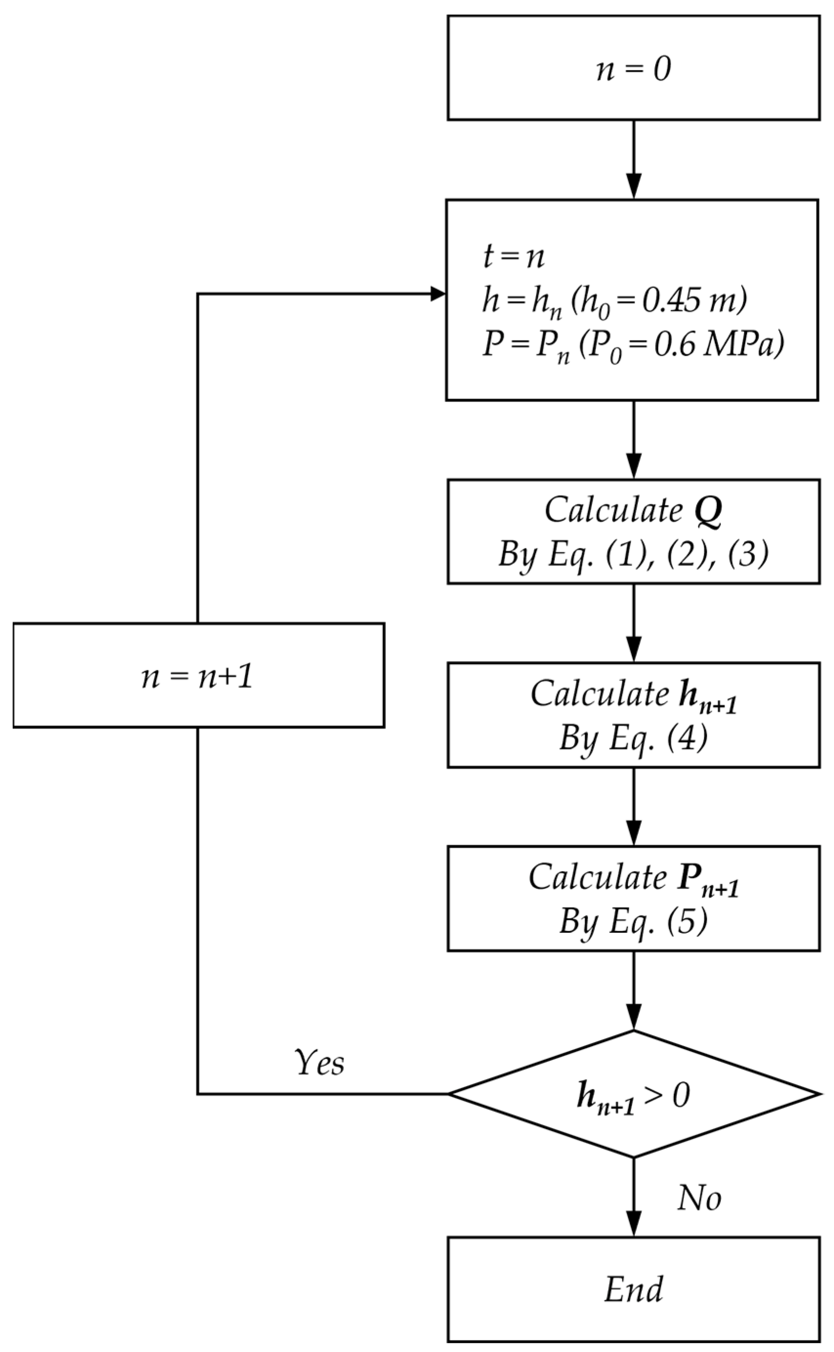
Based on the selected cases, leakage-source modeling was used to numerically calculate changes in leakage amounts, reactor pressure, and liquid levels. This was performed in accordance with the Center for Chemical Process Safety guidelines [35]. Gradual changes in the liquid levels and pressure of the reactor were achieved by calculating them according to the procedure outlined in Figure 3. The liquid levels and pressure of the reactor measured one second after the start of the leak were calculated by determining the leakage rate at zero seconds, after which the result was inserted in the leakage rate equation. Each case was calculated after one second, and repeated until h equaled 0.
Liquid leakage from the pipe system (case 1) is calculated as follows:
Q = A ρ L R e f D 2 L P g c P P a ρ L + g h 16 R e f 180 4 A ρ L l o g 10 1 3.7 ε D + 1.255 R e f D 2 L P g c P P a ρ L + g h R e f 525
where Re denotes the Reynolds number, f denotes the friction coefficient, A denotes the area of the leakage source, D denotes the inner diameter of the pipe, LP denotes the distance between the vessel and the leakage point, P denotes the pressure of the pipe system, PCF denotes the critical flow pressure, Pa denotes the atmospheric pressure, h denotes the height difference between the leakage point and liquid in the facility, and ε denotes the pipe roughness.
Gas leakage from the pipe system (case 2) is calculated as
Q = A M a P 1 γ g c M W R T 1
where γ denotes the specific heat coefficient from the database embedded in Aspen Plus, MW denotes the molecular weight of the leaking substance, R denotes the gas constant, T1 denotes the initial temperature of the pipe, and Ma denotes the Mach number calculated using Excel’s Solver tool. Liquid leakage from the vessel (case 3) is calculated using
Q = C D A ρ L 2 g c P P a ρ L + 2 g h   ,  
where CD is the leakage coefficient calculated with respect to the flow state.
Subsequently, the liquid levels and pressure of the reactor are calculated based on the leakage rate in each case using Equations (1)–(3). The reactor liquid level is derived from the mass balance as
h n + 1 = Q × t n / A × ρ L .
Meanwhile, the reactor pressure is calculated by applying Boyle’s law as follows:
P n + 1 = ( P n × h n ) / h n + 1 .

2.2.3. Development of the Content for the Chemical Accident Response Cases

When complex systems such as oil refinery simulators are involved, training is commonly conducted in small groups of four to six participants (including the chief) under the supervision of an instructor to ensure effective learning. We used this training method and thus constructed a team consisting of a chief (the site supervisor), a field operator who operates the facilities at the worksite, and a boardman who handles the DCS (Figure 4).
To collaborate in the problem-solving process, the field operator and boardman communicated using a two-way radio and were required to continually report their progress to the chief. Moreover, the training system was designed to enable the chief to relay appropriate instructions applicable to the situation to the field operator and boardman.
The training content was developed into scenarios by documenting a series of accident response processes ranging from chemical accidents to release prevention measures. Systematic training pertaining to the chemical accident response process for leakage accidents was provided by categorizing the training into accident occurrence, response, and recovery stages. In the accident occurrence stage, workers are required to report the accident situation promptly and accurately. In the accident response stage, workers wear personal protective equipment and operate manual and automatic safety devices. Finally, in the accident recovery stage, workers carry out processes such as decontamination [36].

2.3. OTS Infrastructure Construction

To create highly realistic training, a DCS was created to facilitate the virtual chemical process identical to the actual process, which was subsequently developed into a GUI [37].

2.3.1. DCS Configuration

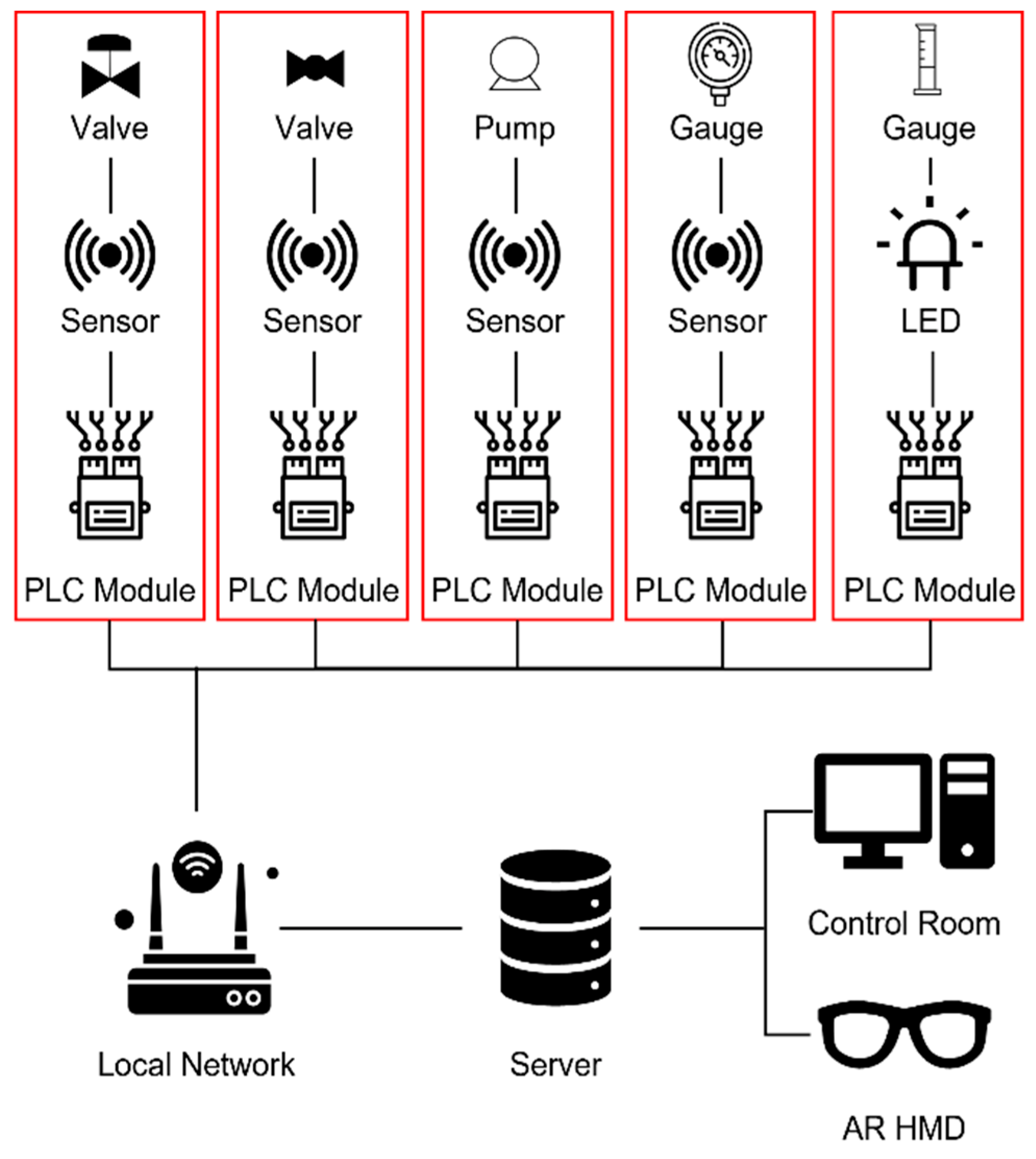
As illustrated in Figure 5, the DCS was designed to transmit the status of the facility in real time when instrumentation devices such as valves are operated.
Since the OTS does not deal with chemicals directly, a sensor was installed in the facility to create a virtual environment, so that users could feel as if the chemicals were actually present. In addition, a programmable logic controller (PLC) module used for automatic control and monitoring was installed in the pilot plant to transmit information between the control room and the worksite. It was configured to transmit and receive data by converting analog signals to digital signals, and it was programmed to transmit and receive signals to and from a computer in the control room and an AR head-mounted display (HMD) in real time. A local network was then configured to exchange signals with each module, and the corresponding values were stored on a server PC.
The DCS was used to transmit the scenario information to the PLC installed in the pilot plant at the beginning of the chemical accident scenario. It was configured to visualize the status of the facility as per the scenario through the instrumentation device attached to the facility. In addition, the system enabled the trainees to confirm the status of the facility through the GUI located in the control room.

2.3.2. Synchronization with the AR System

AR is a graphical technique for merging virtual objects or information into a real environment. The virtual objects resemble objects in the original environment. In this study [38], AR was used as a tool for operating actual devices or visualizing changes in the surrounding environment caused by leakages. Accordingly, the scenario data corresponding to the cases reported in Table 4, as well as the gradual changes in the status of the facility and leakage type, were stored in the database. In addition, chemical accident data were visualized and presented to trainees during the training process via the HMDs they were wearing (Figure 6).

2.4. Construction of the Pilot Plant and Infrastructure

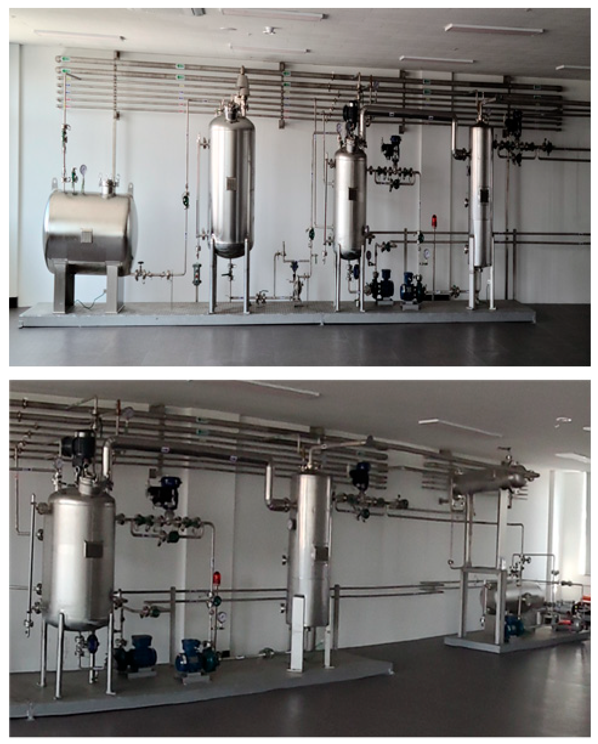
The pilot plant constructed at the training site installed in the research center detailed in Table 3 is illustrated in Figure 7. The pilot plant was designed to imitate chemicals that were moving inside the pipe, thereby eliminating the need for the trainees to handle real chemicals. A sensor was inserted into the instrumentation device to transmit facility information from the control room to the field operator (Figure 8). The PLC module was attached to the back of the instrumentation device for the smooth transmission of information. A motor was attached to the back of the instrumentation device (a bourdon tube) to transmit electrical signals to operate the instrumentation. Ten LED bulbs were vertically attached to the sight glass liquid level meter to display the change in liquid levels.
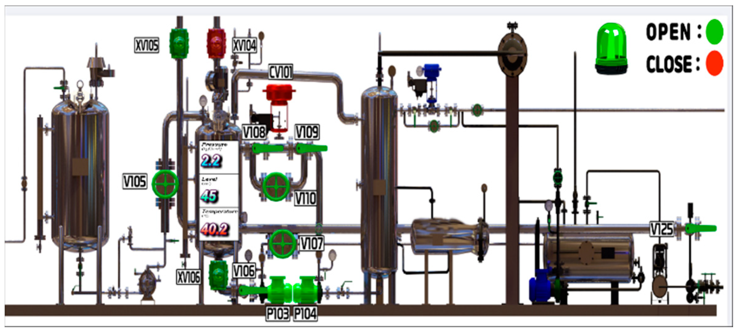
Subsequently, the DCS was built to control the distributed PLC models from a single server PC. A GUI was also designed so that the boardman could respond to chemical accidents in accordance with the accident development process, which was initiated by operating the instrumentation device (Figure 9). Intuitive graphics were applied to the GUI to show the installation location of each device and provide numbers to illustrate the status of the reactor.
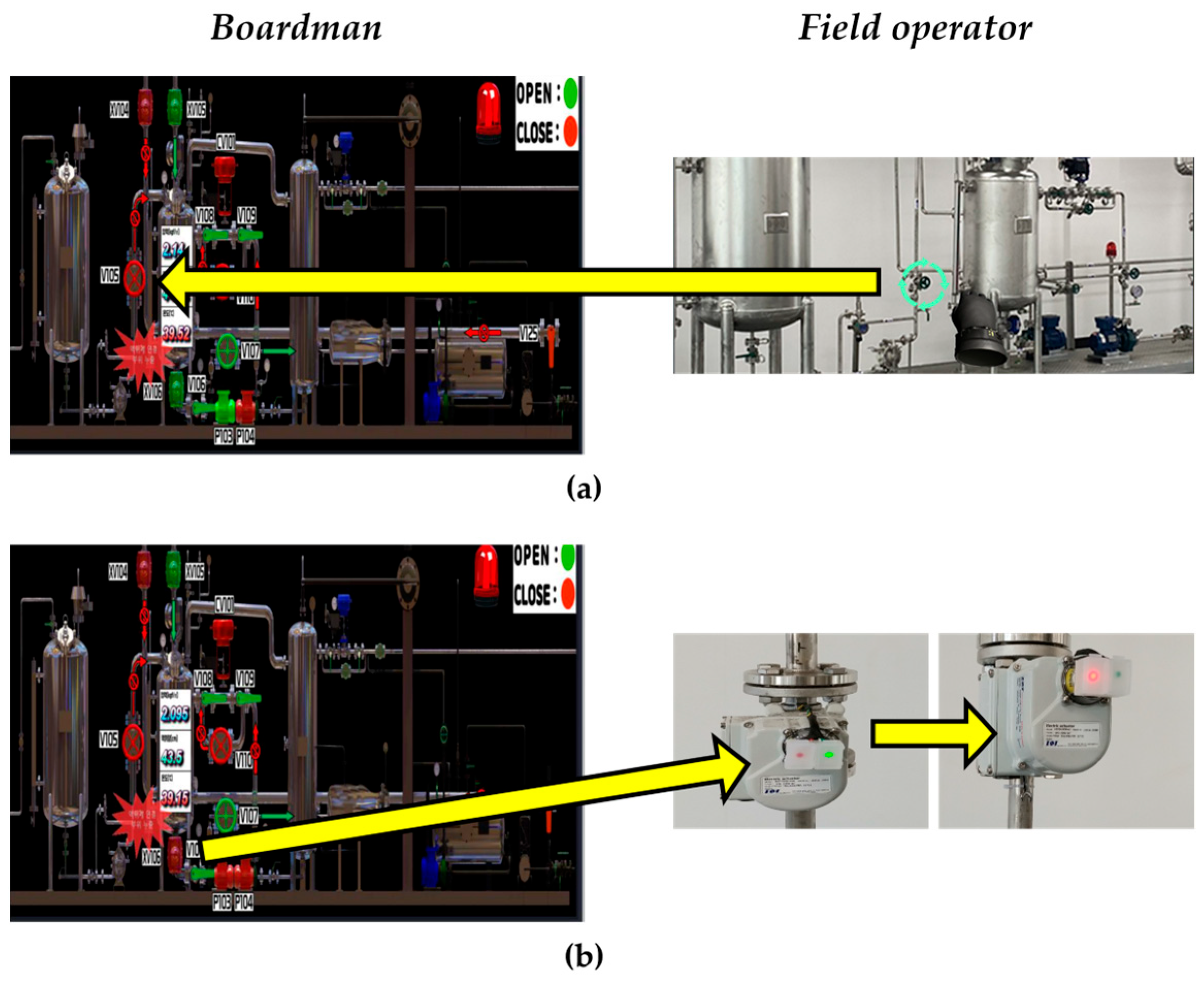
An example of the OTS operation is shown in Figure 10. When a field worker closes a field-installed valve, the icon in the GUI changes from green (Figure 9) to red (Figure 10). Similarly, when a boardman clicks the green valve icon in the GUI, the valve light on the site changes from green to red.

3. Results

3.1. Development of Changes in the Status of the Facility as Training Contents

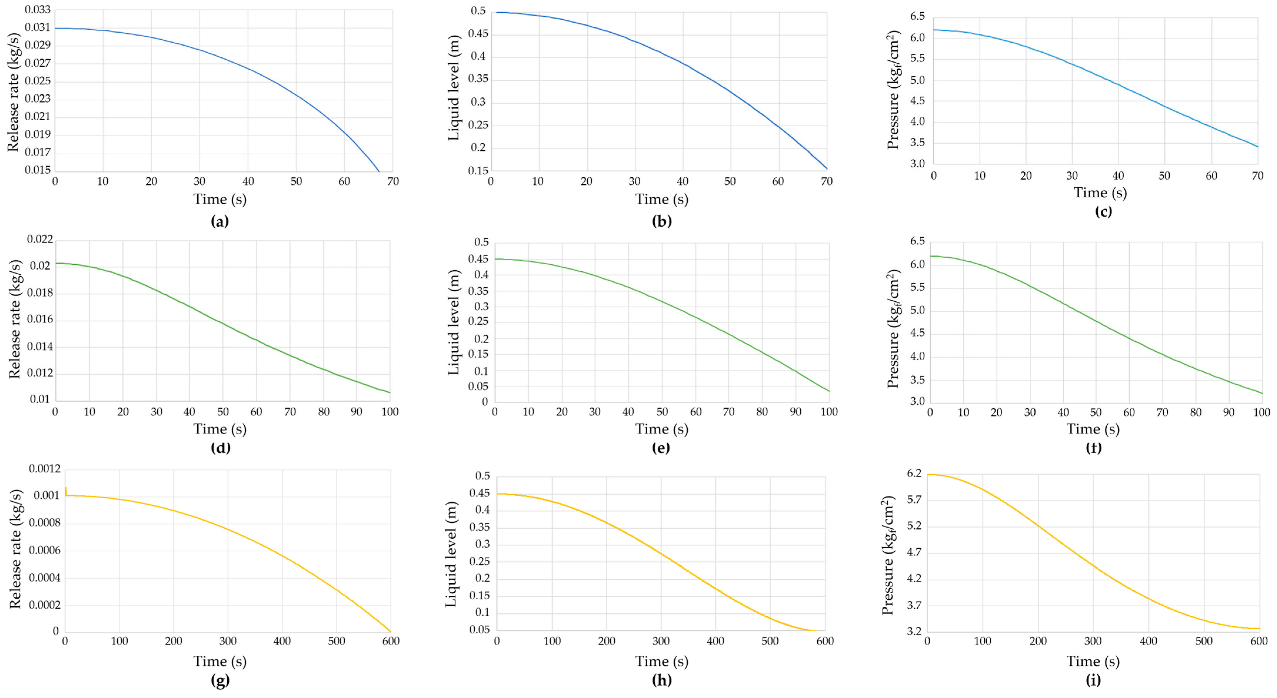
Based on Figure 3, the leakage rate of the reactor, as well as gradual changes in pressure and liquid levels, were derived for each chemical accident case (Figure 11). The results show that the leakage rate was initially high but gradually decreased over time. In particular, in Figure 11, the change in liquid level and pressure is a linear function with Q as a variable (Equations (4) and (5)), and when the diameter of the leak source decreases according to the reduced size, the change in the pilot plant and Q value is small (e) and (h), and (c) and (f) show similar trends. In addition, the liquid levels and pressure were used to confirm the effect of the leakage accident on the chemical facility, and the values were used in the DCS content. The GUI in Figure 8 was programmed to illustrate gradual changes in the status of the reactor in the control room, and the pilot plant was designed to illustrate the changes in the status of the reactor by receiving signals from the liquid level meter and the bourdon tube pressure gauge installed around the reactor. Consequently, we created a tense atmosphere to increase the trainees’ level of immersion in the training.

3.2. Development of Accident Response Scenarios

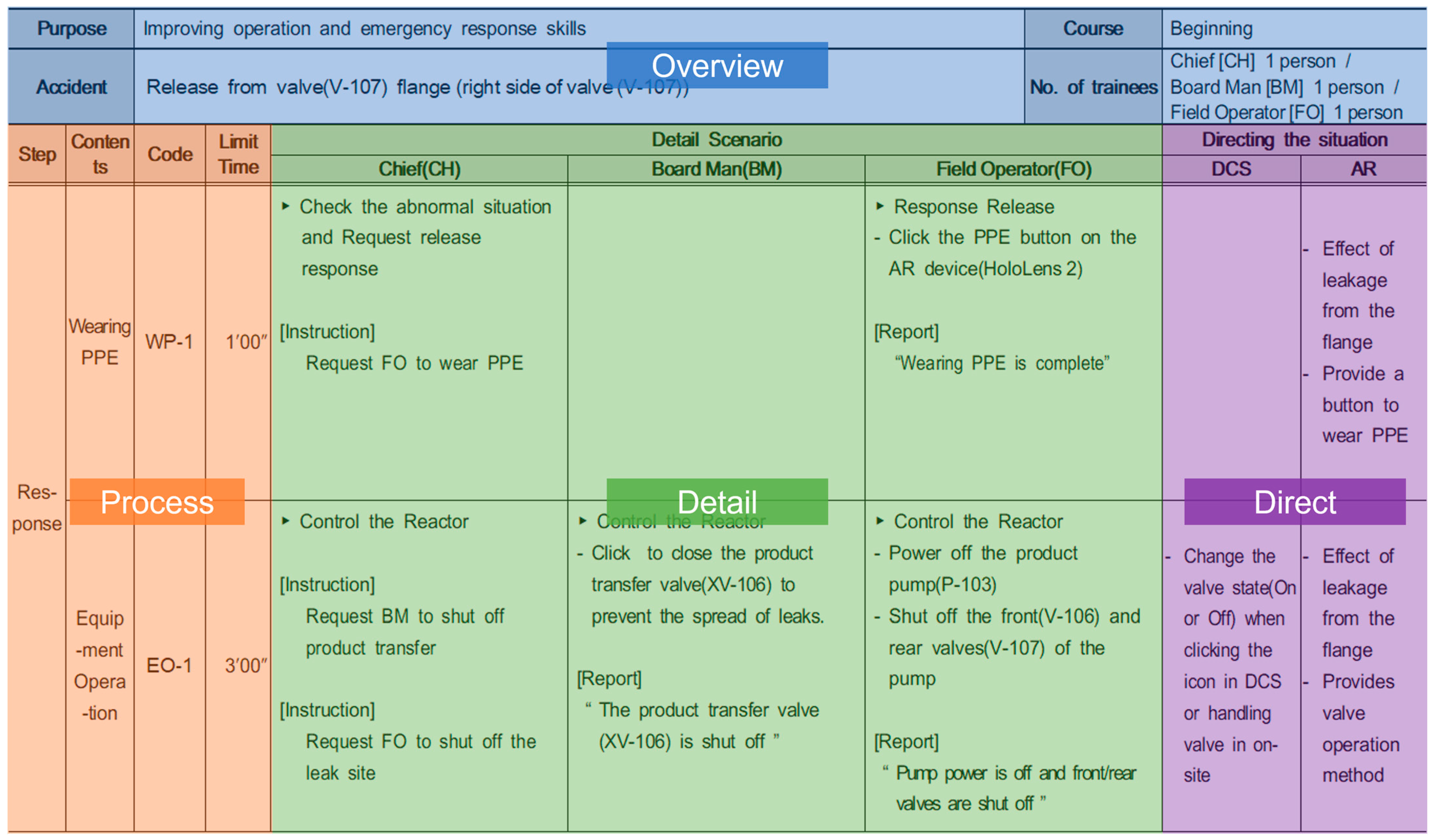
The detailed procedures for each chemical accident response scenario were prepared based on textbooks from related Korean institutions. The scenarios were divided into overview, process, training details, and situational directions (Figure 12). The scenario overview consisted of the purpose of the training, difficulty level, chemical accident case, and recommended number of trainees. The scenario process consisted of the training phase, duration, and identifiable training code, whereas the training details included the instructions, report, and operations to be performed by each role. Finally, to enhance the ability of trainees to understand the system, the directing of the scenario included information on the background arrangements of the DCS screen handled by the boardman and on the AR screen viewed by the field operators.

3.3. Pilot Operation and Results

After installing the pilot plant and control room, we demonstrated the OTS to the trainees. They comprised a field operator who had a background in chemical engineering but no practical knowledge of the field, a boardman with a non-chemical engineering major, and a chief with a chemical engineering major.
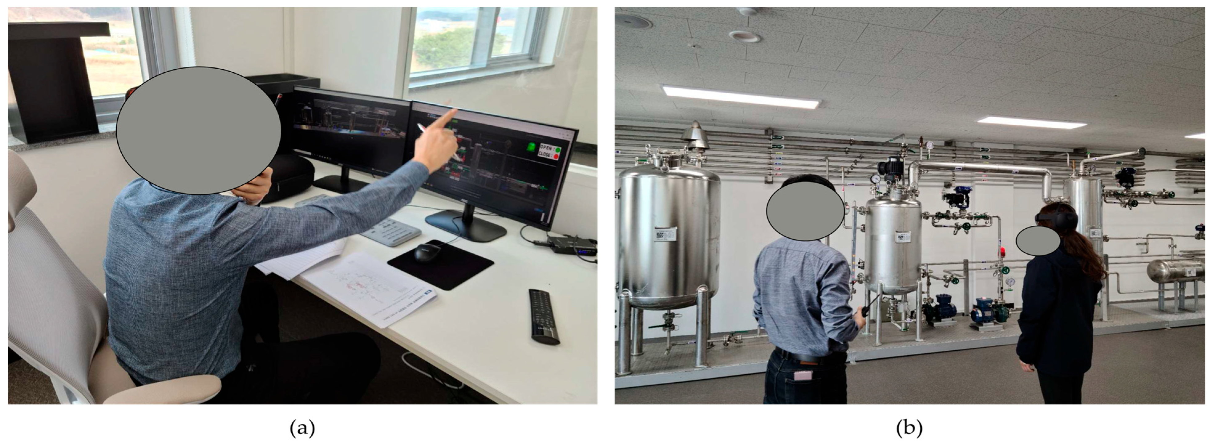
The trainees took appropriate passive–active mitigation measures with respect to the progression of the chemical leakage accidents. As indicated in Figure 13, the boardman used the DCS to monitor the progress of the accident from the control room and used the AR HMD (e.g., HoloLens2) to assess the leakage situation and accident progress on site. From the training, the field operator understood the location and form of the related facilities, as well as their operation and mitigation methods if an accident occurred. Furthermore, the boardman learned the response measures for the facilities with respect to the accident progression.
The readiness of the OTS was evaluated through assessment of the connection status between each segment. The evaluation verified the real-time exchange of information between the sensor and the module located in the pilot plant and server PC. Consequently, this confirmed the possibility of smooth communication between the worksite and the control room.

3.4. Comparison between the OTS and Traditional Training Methods

There are limited comparisons with traditional training in the process industry [13]. However, the OTS considered in this study, which is characterized by mutual cooperation and experiential training, has advantages in terms of training effect and costs. According to the Learning Pyramid of Applied Behavioral Science [39], which is the most cited educational effect, experiential OTS trainees remember approximately 90% of the training content, which is approximately 4.5 times higher than that of conventional lecture-based education. In addition, educational institutions run by Korean government agencies have been conducting lecture-type education for approximately 16 h per session to respond to chemical accidents [40]. However, based on the results of this study, it is possible to educate a series of accident response processes by creating a curriculum of approximately 2 h, including background explanation, OTS session, and after-training discussion. In other words, it is possible to reduce the training time to one-eighth.

4. Conclusions

Existing training methods used in the chemical industry consist of theoretical content delivered in a tedious manner over long periods of time. Moreover, the lack of interaction causes the trainee to lose interest. Accordingly, recent training methods have involved cutting-edge technologies such as VR and AR to enhance the training effect.
The developed OTS can train operators to respond to chemical accidents—from the start of the accident to recovering from it. Specifically, a pilot plant was installed to create an environment similar to an actual chemical plant, and an OTS was developed to enable the trainees to perform a series of processes related to responding to an accident, such as facility operation. In particular, the developed OTS differs from existing training methods in that it allows operators to respond to chemical accidents through mutual cooperation, and it provides hands-on chemical accident response training to field operators while allowing them to actually operate the facility. In addition, compared to the traditional lecture-type training, the training effect is approximately 4.5 times better, and the cost can be reduced by approximately 8 times. The utilization of OTSs is expected to increase, and in the near future the above-mentioned OTS will be tested with a view to qualifying its value for operators or undergraduate students studying chemical engineering.
When applied to industries that entail the handling of chemicals, the developed OTS can train the various participants on the entire chemical accident process in an environment similar to the actual worksite. Furthermore, the trainees do not have to handle actual chemicals. We anticipate that the developed OTS will enable trainees to learn prompt and accurate response processes that apply to emergencies.

Author Contributions

Conceptualization, B.M.; methodology, J.L.; formal analysis, J.L.; writing—review and editing, B.M. and J.L. All authors have read and agreed to the published version of the manuscript.

Funding

The graduate school of chemical characterization hosted by the Korean Ministry of Environment: 2022030903900.

Institutional Review Board Statement

Not applicable.

Informed Consent Statement

Not applicable.

Data Availability Statement

All data have been provided within this manuscript.

Acknowledgments

This research was conducted with the support of the Graduate School of Chemical Characterization hosted by the Korean Ministry of Environment.

Conflicts of Interest

The authors declare no conflict of interest.

References

  1. Zhou, Z.; Huang, J.; Lu, Y.; Ma, H.; Li, W.; Chen, J. A New Text-Mining–Bayesian Network Approach for Identifying Chemical Safety Risk Factors. Mathematics 2022, 10, 4815. [Google Scholar] [CrossRef]
  2. Johnson, C. Why human error modeling has failed to help systems development. Interact Comput. 1999, 11, 517–524. [Google Scholar] [CrossRef]
  3. Zare, A.; Hoboubi, N.; Farahbakhsh, S.; Jahangiri, M. Applying analytic hierarchy process and failure likelihood index method (AHP-FLIM) to assess human reliability in critical and sensitive jobs of a petrochemical industry. Hellyon 2022, 8, e09509. [Google Scholar] [CrossRef]
  4. Xiang, Y.; Wang, Z.; Zhang, C.; Chen, X.; Long, E. Statistical analyasis of major industrial accidents in China from 2000 to 2020. Eng. Fail. Anal. 2022, 141, 106632. [Google Scholar] [CrossRef]
  5. Hemmatian, B.; Abdolhamidzadeh, B.; Darbra, R.; Casal, J. The significance of domino effect in chemical accidents. J. Loss Prevent. Proc. 2014, 29, 30–38. [Google Scholar] [CrossRef]
  6. Jahangiri, M.; Hoboubi, N.; Rostamabadi, A.; Keshavarzi, S.; Hosseini, A. Human Error Analysis in a Permit to Work System: A Case Study in a Chemical Plant. Saf. Health Work 2016, 7, 6–11. [Google Scholar] [CrossRef] [PubMed] [Green Version]
  7. Jung, S.; Woo, J.; Kang, C. Analysis of severe industrial accidents caused by hazardous chemicals in South Korea from January 2008 to June 2018. Saf. Sci. 2020, 124, 104580. [Google Scholar] [CrossRef]
  8. De Beer, J.; Depew, C. The role of process engineering in the digital transformation. Comput. Chem. Eng. 2021, 154, 107423. [Google Scholar] [CrossRef]
  9. Wilk, M.; Rommel, S.; Liauw, M.; Schinke, B.; Zanthoff, H. Education 4.0: Challenges for Education and Advanced Training. Chem. Ing. Tech. 2020, 92, 983–992. [Google Scholar] [CrossRef]
  10. Kumar, V.; Carberry, D.; Beenfeldt, C.; Andersson, M.; Mansouri, S.; Gallucci, F. Virtual reality in chemical and biochemical engineering education and training. Educ. Chem. Eng. 2021, 36, 143–153. [Google Scholar] [CrossRef]
  11. Abdelaziz, M. Challenges and Issues in Building Virtual Reality-Based e-Learning System. Int. J. e-Educ. e-Bus. e-Manag. e-Learn. 2014, 4, 320–328. [Google Scholar] [CrossRef]
  12. Patle, D.; Ahmad, Z.; Rangaiah, G. Operator training simulators in the chemical industry: Review, issues, and future directions. Rev. Chem. Eng. 2014, 30, 199–216. [Google Scholar] [CrossRef]
  13. Garcia Fracaro, S.; Glassey, J.; Bernaerts, K.; Wilk, M. Immersive technologies for the training of operators in the process industry: A Systematic Literature Review. Comput. Chem. Eng. 2022, 160, 107691. [Google Scholar] [CrossRef]
  14. Patle, D.S.; Manca, D. Operator Training simulators in virtual reality environment for process operators: A review. Virtual Real. 2019, 23, 293–311. [Google Scholar] [CrossRef]
  15. Siminovich, C.; Joao, S. Dynamic operator training simulators for sulphuric acid, phosphoric acid, and DAP production units. Procedia Eng. 2014, 83, 215–224. [Google Scholar] [CrossRef] [Green Version]
  16. Nakai, A.; Suzuki, K. Instructional information system using AR technology for chemical plants. Chem. Eng. Trans. 2016, 53, 199–204. [Google Scholar] [CrossRef]
  17. Manca, D.; Brambilla, S.; Colombo, S. Bridging between Virtual Reality and accident simulation for training of process-industry operators. Adv. Eng. Softw. 2013, 55, 1–9. [Google Scholar] [CrossRef]
  18. Szke, I.; Louka, M.; Bryntesen, T.; Edvardsen, S.; Bratteli, J. Comprehensive support for nuclear decommissioning based on 3D simulation and advanced user interface technologies. J. Nucl. Sci. Technol. 2015, 52, 371–387. [Google Scholar] [CrossRef] [Green Version]
  19. Yang, G.; Shao, Z.; Xu, Z.; Zhang, D.; Lou, H.; Wang, K. Development of a novel type operator training simulator framework for air separation process. In Proceedings of the 2021 China Automation Congress (CAC), Beijing, China, 22–24 October 2021; Volume 2021, pp. 4014–4019. [Google Scholar] [CrossRef]
  20. Lee, J.; Cameron, I.; Hassall, M. Improving process safety: What roles for digitalization and industry 4.0? Process Saf. Environ. 2019, 132, 325–339. [Google Scholar] [CrossRef]
  21. Brambilla, S.; Manca, D. Recommended features of an industrial accident simulator for the training of operators. J. Loss Prevent. Proc. 2011, 24, 344–355. [Google Scholar] [CrossRef]
  22. Nakai, A.; Kaihata, Y.; Suzuki, K. The Experience-Based Safety Training System Using Vr Technology for Chemical Plant. Int. J. Adv. Comput. Sci. Appl. 2014, 5, 63–67. [Google Scholar] [CrossRef] [Green Version]
  23. Sharma, C.; Bhavsar, P.; Srinivasan, B.; Srinivasan, R. Eye gaze movement studies of control room operators: A novel approach to improve process safety. Comput. Chem. Eng. 2016, 85, 43–57. [Google Scholar] [CrossRef]
  24. Colombo, S.; Golzio, L. The Plant Simulator as viable means to prevent and manage risk through competencies management: Experiment results. Saf. Sci. 2016, 84, 46–56. [Google Scholar] [CrossRef] [Green Version]
  25. Ahmad, Z.; Patle, D.; Rangaiah, G. Operator training simulator for biodiesel synthesis from waste cooking oil. Process Saf. Environ. 2016, 99, 55–68. [Google Scholar] [CrossRef]
  26. Gerlach, I.; Tholin, S.; Hass, V.; Mandenius, C. Operator training simulator for an industrial bioethanol plant. Processes 2016, 4, 34. [Google Scholar] [CrossRef] [Green Version]
  27. Ouyang, S.; Wang, G.; Yao, J.; Zhu, G.; Liu, Z.; Feng, C. A Unity3D-based interactive three-dimensional virtual practice platform for chemical engineering. Comput. Appl. Eng. Educ. 2018, 26, 91–100. [Google Scholar] [CrossRef]
  28. Puskás, J.; Egedy, A.; Németh, S. Development of operator training simulator for isopropyl alcohol producing plant. Educ. Chem. Eng. 2018, 22, 35–43. [Google Scholar] [CrossRef]
  29. Lee, Y.; Ko, C.; Lee, H.; Jeon, K.; Shin, S.; Han, C. Interactive plant simulation modeling for developing an operator training system in a natural gas pressure-regulating station. Pet. Sci. 2017, 14, 529–538. [Google Scholar] [CrossRef] [Green Version]
  30. Pirola, C.; Peretti, C.; Galli, F. Immersive virtual crude distillation unit learning experience: The EYE4EDU project. Comput. Chem. Eng. 2020, 140, 106973. [Google Scholar] [CrossRef]
  31. Balaton, M.; Nagy, L.; Szeifert, F. Operator training simulator process model implementation of a batch processing unit in a packaged simulation software. Comput. Chem. Eng. 2013, 48, 335–344. [Google Scholar] [CrossRef]
  32. De Tommaso, J.; Rossi, F.; Moradi, N.; Pirola, C.; Patience, G.; Galli, F. Experimental methods in chemical engineering: Process simulation. Can. J. Chem. Eng. 2020, 98, 2301–2320. [Google Scholar] [CrossRef]
  33. Al-Malah Kamal, I.M. Aspen Plus: Chemical Engineering Applications, 1st ed.; John Wiley & Sons Inc.: Hoboken, NJ, USA, 2017; Volume 160, pp. 106–120. [Google Scholar]
  34. Kidam, K.; Hurme, M. Analysis of equipment failures as contributors to chemical process accidents. Process. Saf. Environ. 2013, 91, 61–78. [Google Scholar] [CrossRef]
  35. Center for Chemical Process Safety (CCPS). Guidelines for Consequence Analysis of Chemical Releases, 1st ed.; American Institute of Chemical Engineers: New York, NY, USA, 1999; pp. 15–85. [Google Scholar]
  36. An, S.; Lim, K.; Go, H.; Jung, G.; Ma, B. A study on development of multi-user training contents for response to chemical accidents based on virtual reality. J. Digit. Contents Soc. 2020, 21, 1–10. [Google Scholar] [CrossRef]
  37. Marcano, L.; Haugen, F.; Sannerud, R.; Komulainen, T. Review of simulator training practices for industrial operators: How can individual simulator training be enabled? Saf. Sci. 2019, 115, 414–424. [Google Scholar] [CrossRef]
  38. Garcia Fracaro, S.; Hu, Y.; Gallagher, T.; Loenen, S.; Solmaz, S.; Cermak-Sassenrath, D.; Gerven, T. Immersive Tools for Teaching and Training in a Science and Technology Environment—First CHARMING Policy Brief. 2021, pp. 1–7. Available online: https://charming-etn.eu/wp-content/uploads/2021/04/D5.4_CHARMING_Policy_Brief.pdf (accessed on 17 January 2023).
  39. Letrud, K.; Hernes, S. The diffusion of the learning pyramid myths in academia: An exploratory study. J. Curric. Stud. 2016, 48, 291–302. [Google Scholar] [CrossRef]
  40. Education System of National Institute of Chemical Safety of Korean Ministry of Environment. Available online: https://edunics.me.go.kr/academy/contents/view.do?contentsNo=14&menuCd=WWW001009001 (accessed on 1 January 2023).
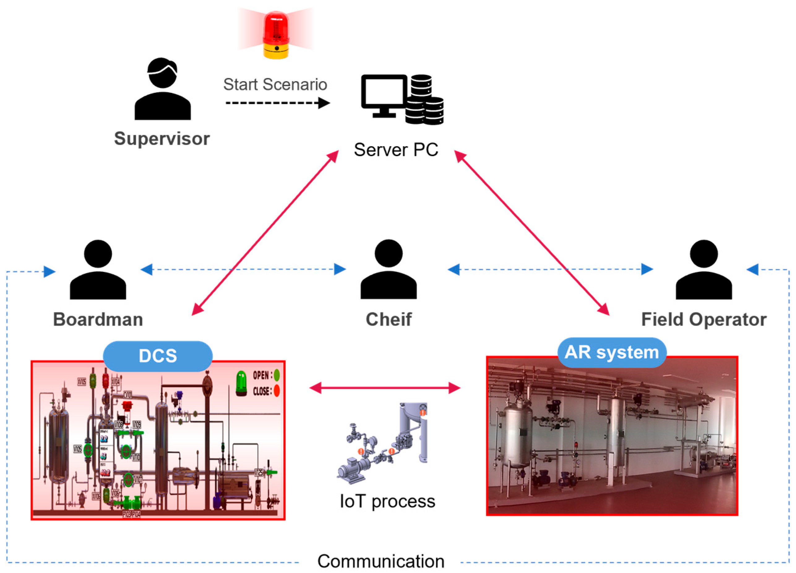
Figure 1. OTS configuration. DCS, distributed control system; IoT, internet of things.
Applsci 13 01382 g001
Figure 2. A flowchart of the continuous process for training. HOR, hot oil return; HOS, hot oil supply; CWR, cooling water return; CWS, cooling water supply.
Applsci 13 01382 g002
Figure 3. Calculation flowchart for Q, h, and P.
Applsci 13 01382 g003
Figure 4. The roles and communication systems of the participants.
Applsci 13 01382 g004
Figure 5. The structure of the DCS.
Applsci 13 01382 g005
Figure 6. The structure of the AR system.
Applsci 13 01382 g006
Figure 7. A photograph of the installed pilot plant.
Applsci 13 01382 g007
Figure 8. Valve and instrumentation device testing.
Applsci 13 01382 g008
Figure 9. The OTS GUI.
Applsci 13 01382 g009
Figure 10. Example of the OTS operation. (a) GUI change according to manual valve operation. (b) Changes in valves installed on site according to the DCS operation.
Applsci 13 01382 g010
Figure 11. Changes in release rate, reactor liquid level, and pressure over time. Case 1: (a) release rate, (b) liquid level, and (c) pressure. Case 2: (d) release rate, (e) liquid level, and (f) pressure. Case 3: (g) release rate, (h) liquid level, and (i) pressure.
Applsci 13 01382 g011
Figure 12. An accident response scenario example.
Applsci 13 01382 g012
Figure 13. The training scene. (a) The boardman in the control room, and (b) the field operators on site.
Applsci 13 01382 g013
Table 2. Key materials for the pilot plant.
Equipment ItemAbbreviationCapacity
(m3)
Operating Pressure (MPa)Operating Temperature (°C)Phase
Storage tankTK-1010.5AMBAMBLiquid
ReactorR-1010.30.670Liquid/gas
ColumnT-1010.10.3 (1 stage)-Liquid/gas
Reflux DrumD-1010.180.325Liquid/gas
CondenserC-1010.0050.5-Liquid/gas
VesselV-101 A/B0.09/0.550.8AMBGas
Table 3. Design and operation specifications for the pilot plant.
DivisionChemical FormulaCAS No.Boiling Point (°C)Vapor Pressure (mmHg)
HexamethyldisilaneSi2C6H181450-14-211320.8
Hydrogen chlorideHCl7647-01-0−85.0535.42
TrimethylsilaneC3H10Si993-07-76.7594
TrimethylchlorosilaneC3H9SiCl75-77-457200
Table 4. Accident scenarios for training.
Case No.ScenarioSituationResponseLeakage Model
1Piping failure 1Leakage from a flange gap due to gasket aging.Close the valve and shut off the pump.Liquid leakage from the pipe
2Piping failure 2Leakage due to corrosion of the hydrochloric acid supply pipe.Close the valve connected to the reactor.Gas leakage from the pipe
3Level gauge leakageLeakage at the bottom of the reactor due to poor welding.Block the inflow and outflow by closing the valve connected to the reactor.Liquid leakage from the vessel
Disclaimer/Publisher’s Note: The statements, opinions and data contained in all publications are solely those of the individual author(s) and contributor(s) and not of MDPI and/or the editor(s). MDPI and/or the editor(s) disclaim responsibility for any injury to people or property resulting from any ideas, methods, instructions or products referred to in the content.