Article

The Damage and Impulse Transfer Characteristics of Flexible Steel V-Structures with Large Bend Radii

by
Vinay R. Shekhar
1,
Christopher J. von Klemperer
2 and
Genevieve S. Langdon
1,3,*
1
Blast Impact and Survivability Research Unit, Department of Mechanical Engineering, University of Cape Town, Rondebosch, Cape Town 7700, South Africa
2
Department of Mechanical Engineering, University of Cape Town, Rondebosch, Cape Town 7700, South Africa
3
Department of Civil and Structural Engineering, University of Sheffield, Sheffield S10 2TN, UK
*
Author to whom correspondence should be addressed.
Appl. Sci. 2023, 13(3), 1293; https://doi.org/10.3390/app13031293
Submission received: 12 December 2022 / Revised: 10 January 2023 / Accepted: 11 January 2023 / Published: 18 January 2023
(This article belongs to the Special Issue Explosion Effects in the Built Environment)

Abstract

:
This paper reports results from an experimental and computational study on the influence of bend radius and internal angle on the damage and impulse transfer characteristics of flexible steel V-structures subjected to localized explosion loading. This issue has bearing on the manufacturing of V-hulls used for Mine Resistant Ambush Protected vehicles used around the world. Global impulse transfer, damage and transient deformation were measured during small-scale explosive detonations on 1:8-scale V-structures. The work found that increasing the bend radius to values that can be used in practical manufacturing generated damage that was less localized than the damage observed in V-structures with tighter bend radii. High-speed imaging was able to measure transient deformation that was maximal in the centre, and lower elastic post-peak vibration magnitudes at high charge masses. The impulse transfer increased as the bend radius increased and the internal V-angle increased. Since V-structures with tighter bend radii exhibit less permanent deformation and higher deformation gradients, they will be more prone to localized ruptures when deployed for blast protection, whereas structures with larger tip radii will need a larger region of the V-structure repaired after a blast event but may be less prone to rupturing when the blast loading is localized.

1. Introduction

Mine Resistant Ambush Protected (MRAP) vehicles are used by the military in urban and confined areas. They are deployed in command and control reconnaissance missions, to support convoy movements, to conduct medical evacuations and in explosive ordinance disposal [1]. MRAPs have a long history dating back to the conflicts in Southern Africa [2] but are still in use today The United States recently agreed to deliver 440 MaxxPro MRAPs as part of its military support for Ukraine during 2022 [3].
MRAPs usually employ V-shaped hull structures to protect their passengers from the devastating effects of improvised explosive devices and anti-vehicle landmines when detonated beneath the vehicles. Huge amounts of energy are released when explosive charges are detonated, and this is directed towards the MRAP vehicle’s hull through the blast shock front. Without any means to mitigate the blast, the explosion will cause localized structural damage and exert large global accelerations on the vehicle’s structure. The vertical momentum transfer may cause the vehicle to move upwards, injuring the passengers. If the localized structural damage results in floor rupture, the blast shock, fragments, ejecta (if a buried charge is detonated), fireball and explosion products will enter the MRAP with potentially lethal effects.
The V-structures used in MRAP vehicles mitigate the blast by laterally deflecting the explosive shock waves away from the passenger compartment, reducing the loading transmitted through the compartment floor and lowering the vertical global impulse transfer to the vehicle [2,4,5,6]. Over the last 50 years, the use of V-structures has reduced injury rates from explosive charges detonated under the centre of vehicles’ undersides [7].
Various researchers [5,8,9,10,11,12,13,14,15,16,17,18] have studied the impulse and permanent damage imparted to scaled versions of these V-structures. This work often involved small-scale explosive testing on flexible structures [5,8,9,10,11,12] and numerical simulations using hydrocodes [4,13,14,15,16,17,18,19,20]. Damage was observed in the form of large plastic deformation and the presence of ridge buckling [5,8]. The damage was localized to the immediate vicinity of the explosion (directly beneath the apex of the V-structure). The results showed that the impulse transfer strongly depended on the internal V-angle [5,9,10,11,12,13,14]; lower internal angles were more effective mitigators, as might be expected, given that the mitigation mechanism was lateral blast-load deflection. The superiority of the V-structure over other designs has been demonstrated for both air-blast and buried explosions [13,14,15,16,17,18,19,20].
Numerical studies by Trajkovski et al. [17] confirmed that the internal V-angle was the major factor in influencing the initial plate acceleration and was even more significant for impulse transfer. However, lowering the internal angle raises the vehicle height: this has a detrimental effect on the handling performance, increases the battlefield silhouette (for combat arenas) and lowers vehicle mobility by raising the centre of mass [6,21].
Full-scale experiments of MRAP vehicles are not generally reported in the open literature, but results from LS-Dyna simulations of a “typical” full-scale MRAP vehicle have been published [22]. A small flat section at the ridge of the V-structure that comprised the vehicle hull bottom was apparent, probably due to the practical difficulty of manufacturing a V-structure with a tight bend radius. This raises some questions about the applicability of other work [5,8] using a very tight bend radius of 2 mm. The V-structure simulations in [22] exhibited lower floor accelerations, kinetic energy and reductions in the local and global maximum velocities when compared to the same charge detonation under a vehicle with a flat bottom. Concerns were raised about the stability of the vehicle and the reduced interior space.
Attempts to improve the mitigating properties of V-structures included the proposed use of compound V-angles [23,24], and others [25,26] studied the utilization of a series of multiple shallow V-structures. These compound and multi-V structures have yielded mixed results, and no clear improvement to the traditional V-structure has been obtained. Erdik [27] showed that use of a sandwich V-structure with a relatively weak and compressible honeycomb core may offer some additional protection. The sandwich V-structures required relatively large bend radii in their construction.
A recent numerical study examined the influence of the bend radius (of the “V-tip” at the apex of the V-structure) and internal angle on the impulse transfer from explosions at different stand-off distances [4]. The model was validated using experimental results on rigid V-structures with sharp tips (effectively a bend radius of zero). The results indicated that impulse transfer was sensitive to the bend radius when the stand-off distance was kept constant, such that more impulse was transferred when the bend radius was increased (but since the ground clearance was reduced, this is viewed as a potential benefit). When the ground clearance was kept constant, the stand-off distance increased with increasing bend radius, and no measurable difference in global impulse transfer could be distinguished.
As the computational simulations in [4] employed a rigid model for the V-structure, the spatial distribution of the impulse across the structure and its influence on ensuing damage were not considered. This also means the prospect of material rupture in the V-structure (and potential ingress of shock, ejecta, combustion products and high-velocity fragmentation) was not considered. Material rupture can occur at low levels of permanent deformation in materials with high strength and low plastic capacity [28], so the transient response of structures (including rupture) should be measured to provide a more thorough assessment of the V-structure’s protective capacity.
Although V-structures have been researched for many years [4,5,6,7,8,9,10,11,12,13,14,15,16,17,18,19,20,21,22,23,24,25,26], the influence of bend radius may be a significant but overlooked factor in the blast-mitigation efficacy of V-structures. We sought to address this issue through an experimental study on the influences of bend radius and internal angle on the transient displacement, permanent damage and impulse transfer characteristics of flexible, steel, 1:8-scale V-structures subjected to blast loading. This will show, for the first time, the relative importance of bend radius as an influencing factor (compared to internal V-angle).

2. Materials and Methods

2.1. Specimen Design and Selection

V-structure specimens were scaled down from a representative MRAP to 1:8.3 scale [5]. Geometrically similar scaling of a TM-57 anti-vehicle landmine (with an effective explosive diameter of 316 mm) and a popular armoured personnel carrier (approximate width of 2.5 m, ground clearance of 0.41 m) fixed the specimen width at 300 mm. The V-structures were manufactured by folding nominally 2 mm thick Domex 700 MC steel into the required geometry using a CNC plate bender. Three variants were produced: (i) a 105° internal angle with an external tip radius of 32 mm, (ii) a 105° internal angle with an external tip radius of 62 mm, and (iii) a 120° internal angle with an external tip radius of 32 mm. An example of the folded profile of a typical blast test specimen is shown in Figure 1.
The V-structure design and mounting system were based on numerical simulations reported in [4], with a cross-cut width of 300 mm and a ridge length of 300 mm. The sheet thickness was measured to be 2.08 ± 0.06 mm. The 105° V-structures had a mass of 2.31 ± 0.01 kg, and the 120° V structures were 2.19 ± 0.004 kg. The two vertical sides of the V-structures were machined with six equi-spaced clearance holes for M12 bolts, positioned 25 mm from the edge with 50 mm centre-to-centre distances.

2.2. Explosion Test Method

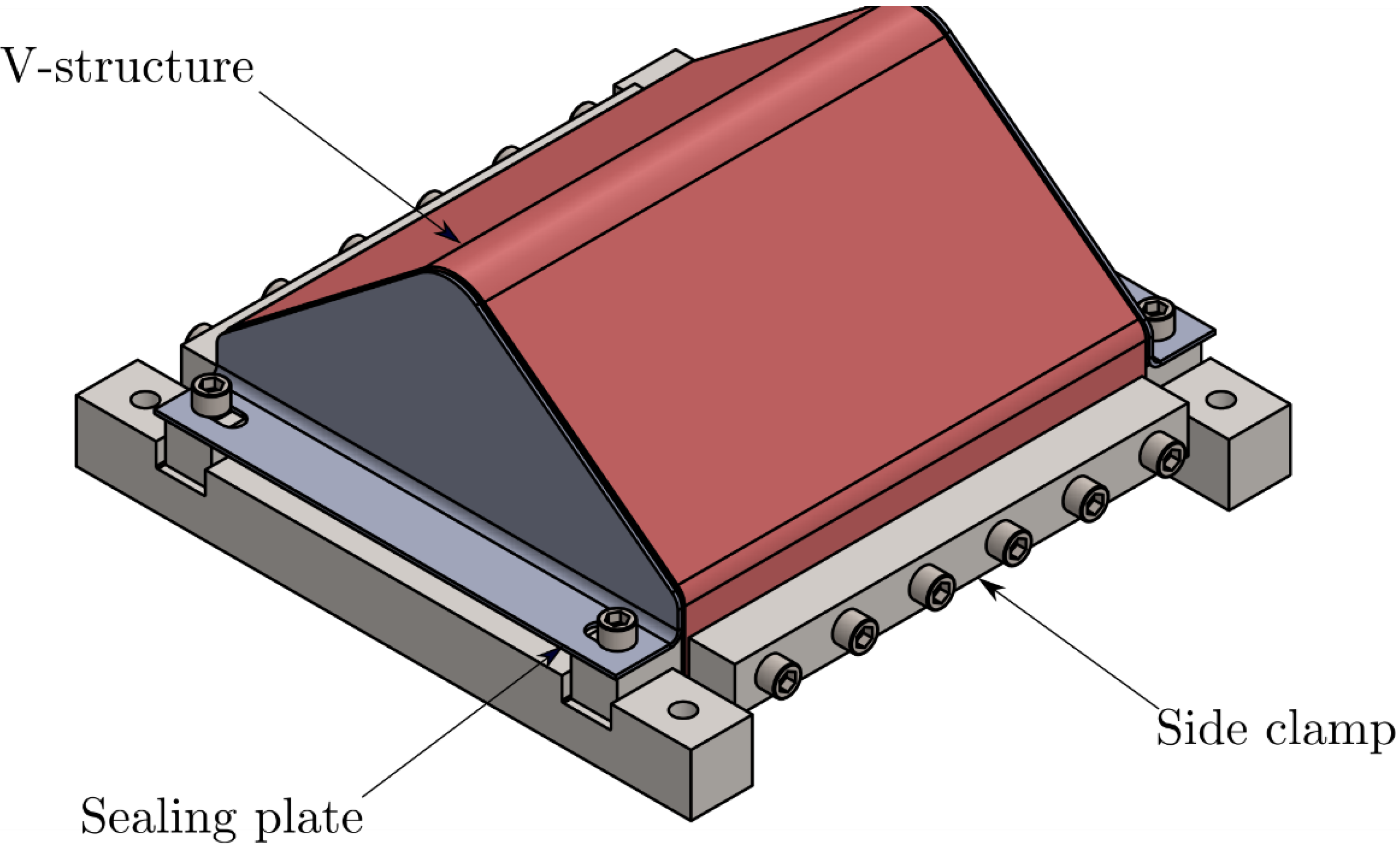
The experimental method was based on previous numerical work [4] that modified the methodology used by Chung Kim Yuen et al. [5]. The geometrically similar scaling in [5] suggested an explosive charge diameter of 38 mm and a stand-off distance of 50 mm. In this work, the 38 mm charge diameter was used, but the stand-off distance was decreased to 34 mm to obtain large plastic deformation in the central region of the specimens. The V-structure specimens were mounted onto a purpose-built rig and clamped along the two vertical edges using a side clamping system, as shown in Figure 2.
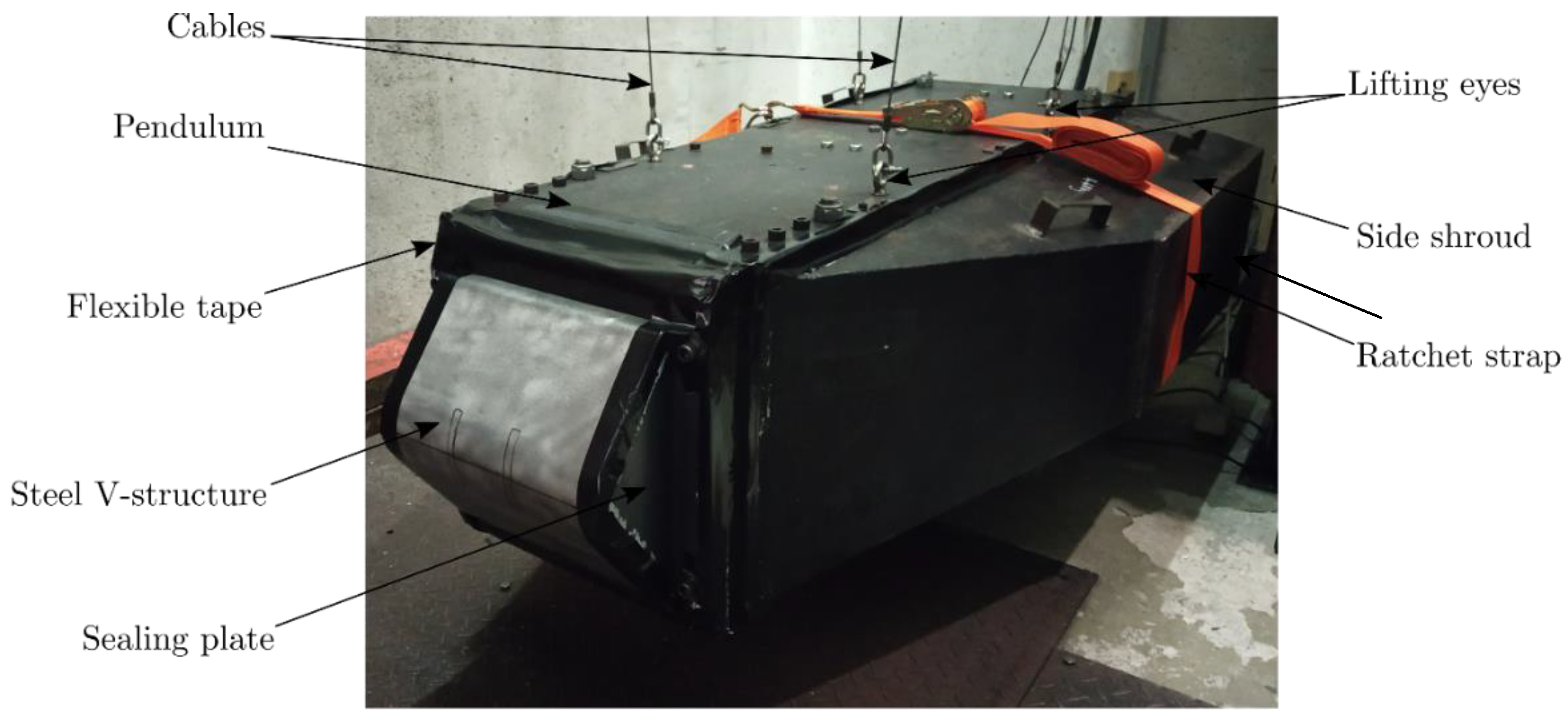
The clamp design minimized unrealistic recirculation of the pressure at the clamped interfaces, allowing the blast pressure to deflect laterally and flow away without artificially increasing the global impulse transfer. To prevent leakage of the explosion’s gas products and dust ingress through the free sides, sealing plates were attached to the mounting frame. The small gaps between the sealing plates and the V-structure were covered using flexible adhesive tape; this prevented ingress but allowed the sides of the specimen to move without significant constraint. A photograph of the experimental arrangement prior to blast testing is shown in Figure 3.
The blast loading was created by rear-detonating 10–40 g of plastic explosive PE4 discs in air. The discs were located at the midpoint of the V-ridge at a pre-determined stand-off distance (SOD) of 34 mm using a polystyrene bridge [5,29,30]. An electrical detonator with a 6 mm diameter was used to detonate the explosive discs. The detonator was pushed 1 mm into the rear of the PE4 disc at its radial centre.

2.3. Experimental Instrumentation and Measurements

Due to the close proximity of the charge to the target plate, it was not possible to record useful pressure-time data; however, a global impulse transfer to the V-structure was inferred from the pendulum swing. A high-speed stereo-imaging system was used in selected experiments when the risk of material rupture (and ingress of shock and particulates from the explosion) was low. The cameras were mounted inside the pendulum onto vibrationally isolated aluminium rails. External shrouds prevented the explosive flash and any wrap-around blast loading from interfering with the internal instrumentation, as shown in Figure 3. The shrouds were mounted via small bolts to the pendulum frame but were subjected to large vibrations from the explosive detonations, so a ratchet strap was used as additional support in case the bolts failed.
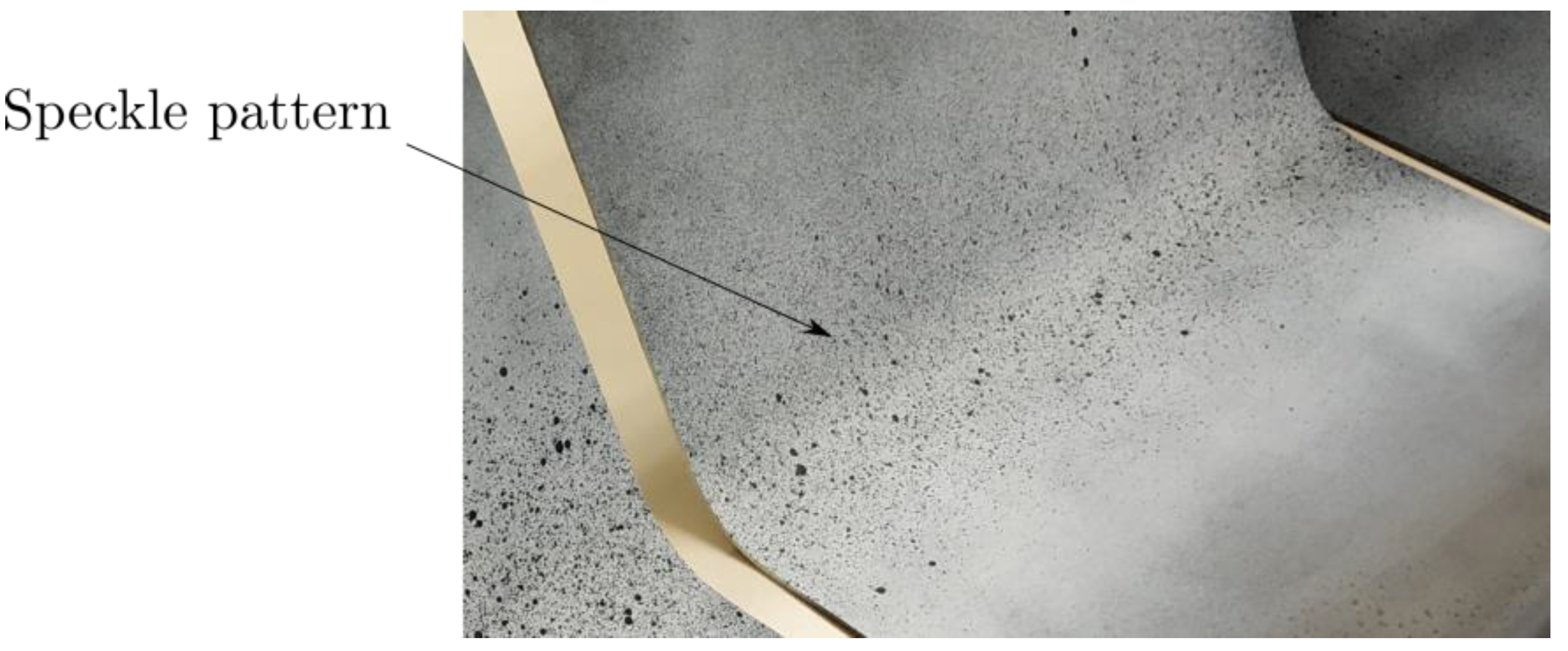
Only the middle part of the V-structure could be filmed due to depth-of-field limitation, in 1024 by 760 pixels. The rear surface of central V-ridge was sand-blasted and treated with acetone wipe before being painted with a black and white random speckle pattern (with an average speckle size of approximately 0.8 mm), as shown in Figure 4. Two high-speed monochrome IDT NRS4 cameras (filming at 33 kfps with an exposure time of 31 µs) and LED lighting were positioned to provide a clear field of view of the central strip, following Curry and Langdon [26]. The stereo-imaging system was calibrated to find the system projection and distortion parameters. A 19 × 19 pixels subset size and a grid spacing of 4 pixels were maintained for all tests. Digital image correlation was employed to analyse the captured images and obtain the out of plane transient displacement along the V-ridge.
After testing, the V-structures were inspected for damage, and a 3D scanner was used to obtain the out-of-plane deformation shape whilst the specimens were still mounted in the clamp frame. The cloud created by the 3D scanner was processed to obtain final deformed section profiles along the V-ridge and transverse to the ridge (the cross-cut direction).

3. Experimental Results

3.1. Permanent Damage Characteristics

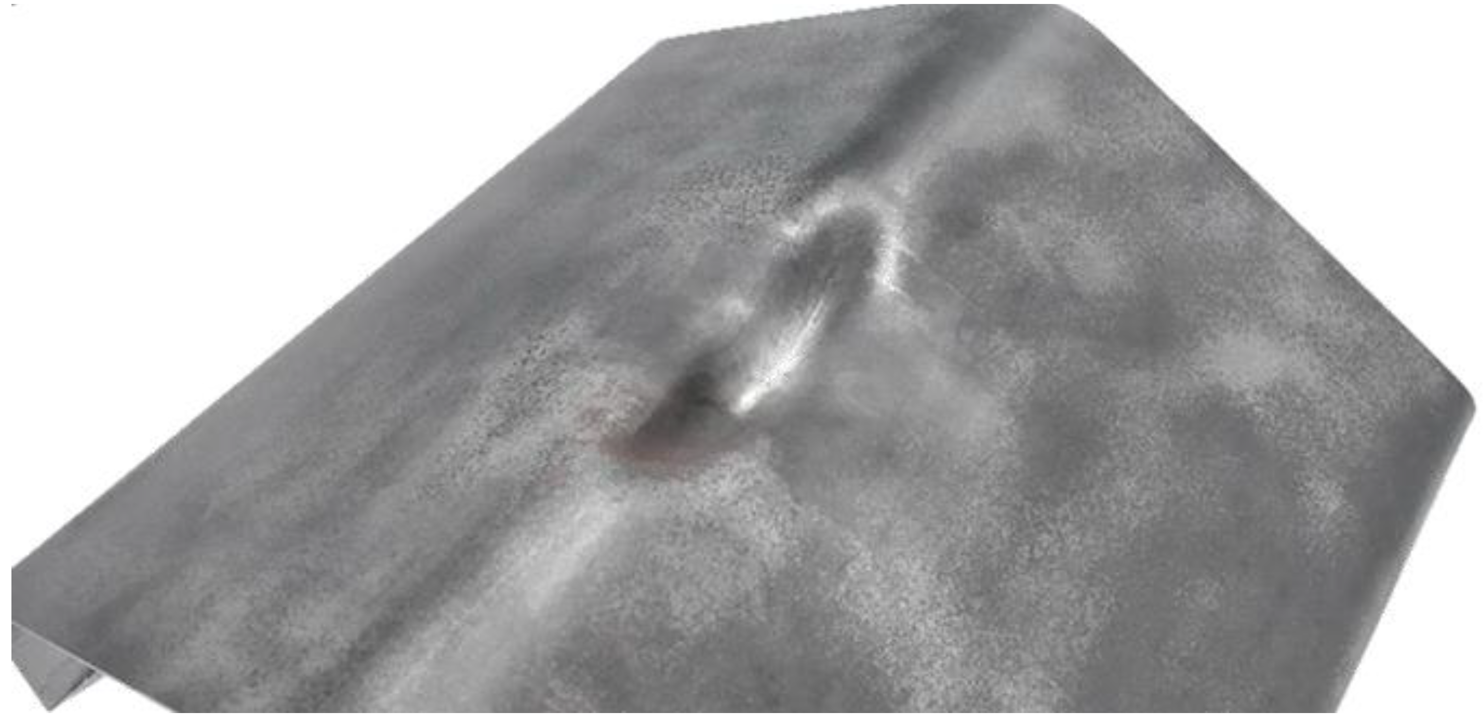
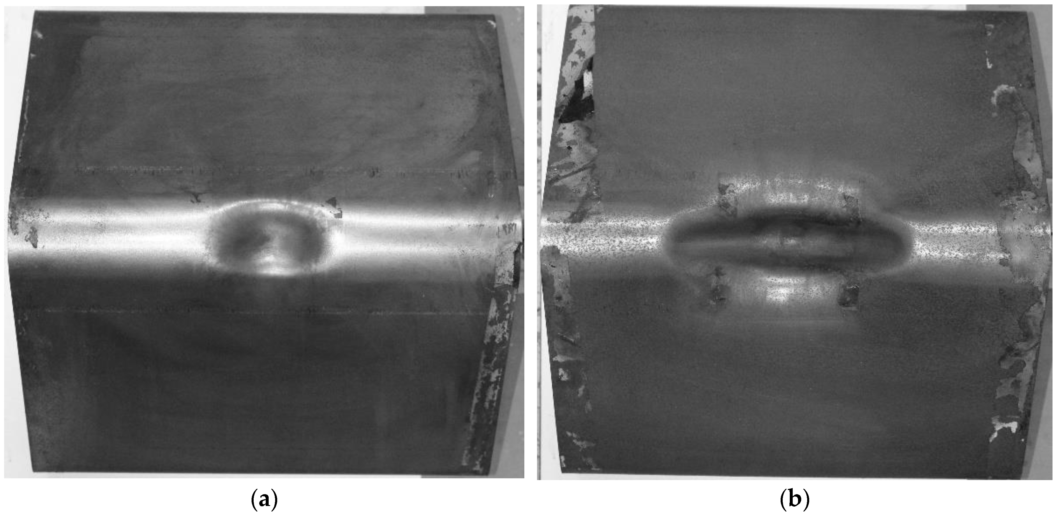
All the blast-tested V-structures exhibited damage in the form of extensive plastic deformation in the region in close proximity to the detonation (the central part of the structure). Photographs of typical damage are shown in Figure 5 and Figure 6. The central ridge plastically deformed inwards, as shown in the photographs in Figure 5 and Figure 6. As charge mass was increased, the deformation increased in magnitude and a larger proportion of the ridge was affected, as shown by comparing the damaged regions in Figure 6a (10 g) and Figure 7b (40 g). This is in contrast with the deformation mode observed in similarly loaded V-structures with a much tighter 4 mm tip radius in [5], where the ridge barely deformed and the inclined sheeting plastically deformed inwards and pinched behind the ridge.

3.1.1. 105° Internal Angle V-Structures

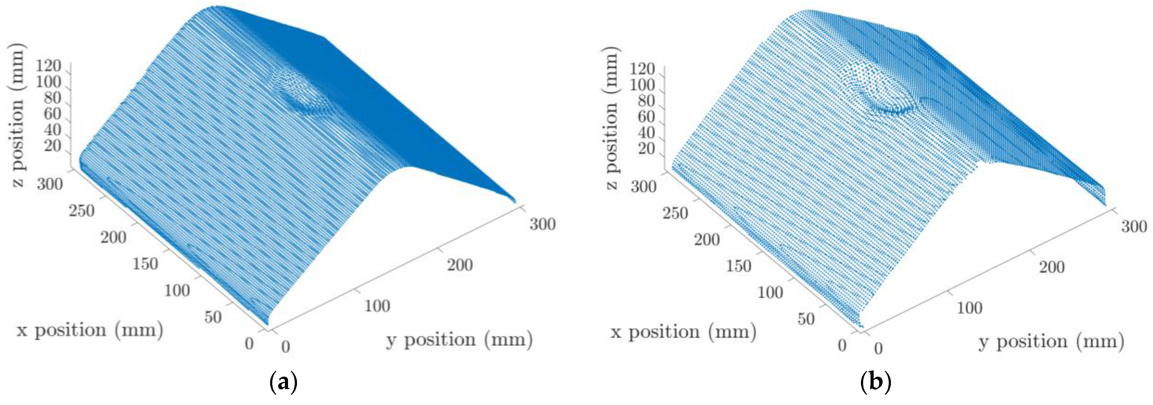
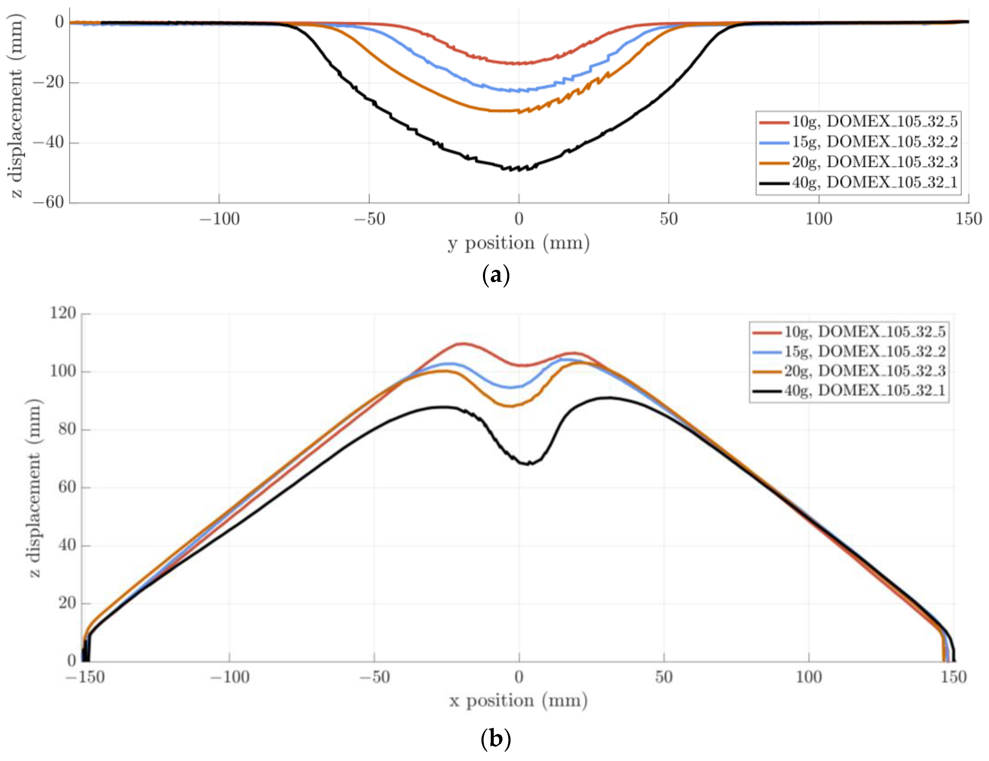
Figure 7 shows the deformed 3D profile plots for blast tested V-structures (105° internal angle, 32 mm tip radius) for different charge masses. As expected, higher charge masses caused greater amounts of damage. There was an increase in the total deformed area and larger permanent displacements. The permanently deformed profiles along the ridge and the cross-cut planes in Figure 8 for the same tests show this more clearly. Along the ridge, the deformed region at 10 g covered one third of the width, whereas at 40 g, the deformed region was approximately two thirds of the width. However, in the crosscut (transverse) direction, the deformed area was more localized. The magnitude of the displacement increased with charge mass in both directions. At the highest charge masses, the central deformation caused some rotation of the inclined sheets at the outer bend radii (near the clamped edges). Complete inversion of the ridge is evident in the cross-cut profiles in Figure 8b.
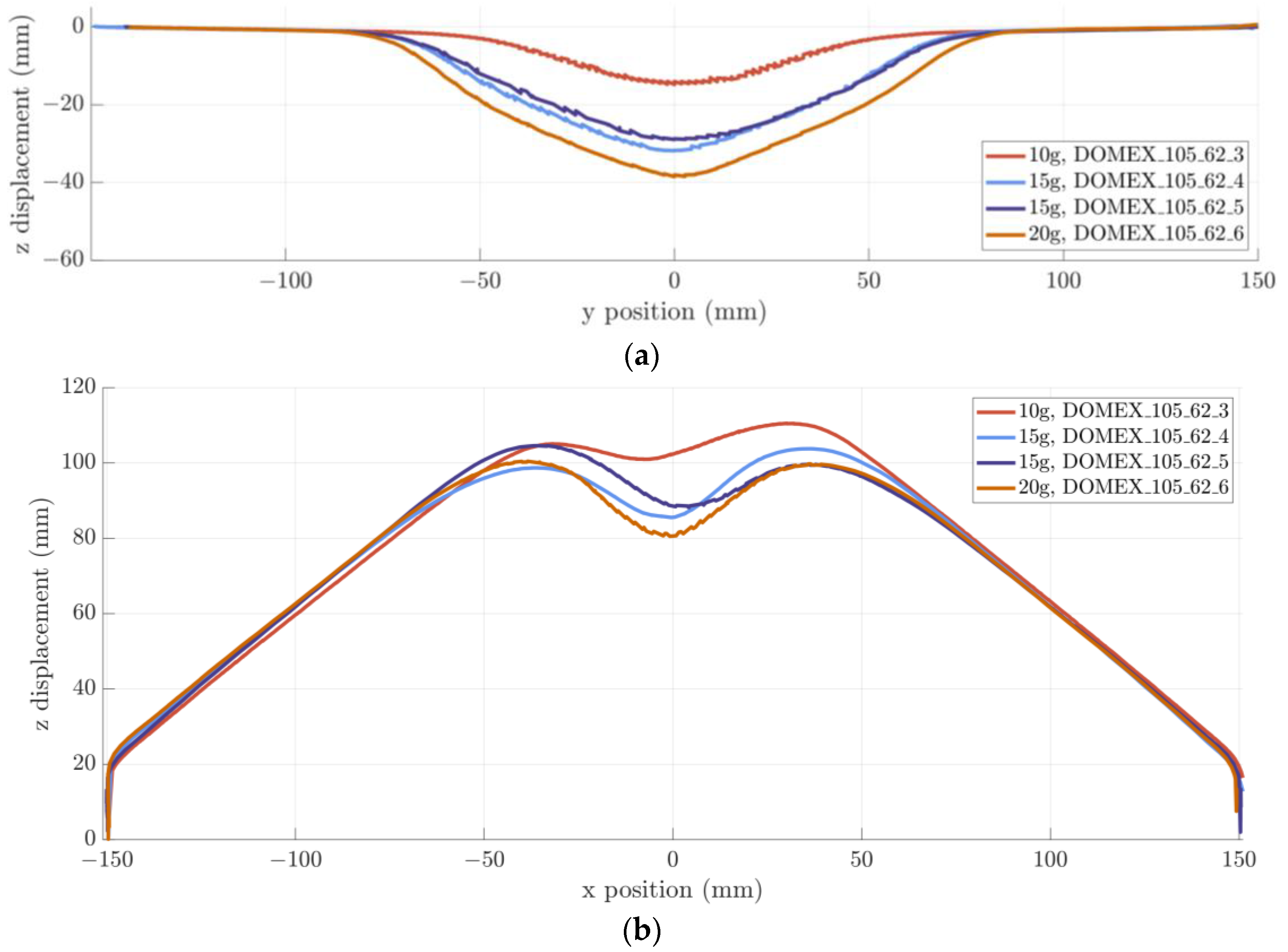
For the 105° V-structures with the larger tip radius of 62 mm, the deformation is less localized in both the crosscut and ridge directions, as shown in Figure 9. These specimens exhibited larger displacements for the given charge mass when compared to their 32 mm tip radius counterparts. As the ridge area has lower plastic stiffness due to the increased bend radius, there is no visible angular rotation at the boundary edges in the cross-cut profiles, despite the larger permanent mid-point displacement.

3.1.2. 120° Internal Angle V-Structures

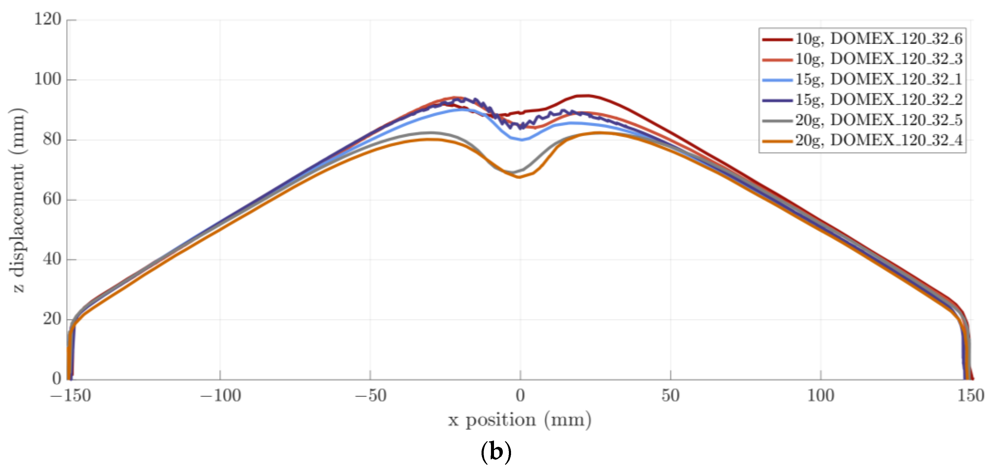
The permanently deformed profiles of the 120° V-structures with a tip radius of 32 mm were similar to the 105° panels of the same bend radius in the ridge direction, as shown in Figure 10a. However, the deformation in the cross-cut plane (in Figure 10b) was less localized than exhibited by 105° V-structures, probably due to the decrease in overall structural rigidity. Good repeatability of the deformed profiles, in both directions, in the repeated 10–20 g detonations, was observed.

3.2. Impulse Transfer and Permanent Displacement

A graph of impulse transfer versus charge mass is shown in Figure 11. Similar impulses were transferred by the three types of V-structure during the 10–15 g charge mass detonations. At 20 g, the 105° V-structures outperformed the 120° specimens, through lower impulse transfer. It also appears that the 32 mm tip radius is more effective at reducing impulse transfer than the 62 mm radius at 20 g. These were both expected results. The lower internal angle is known to be better at laterally deflecting the blast pressure [9,10,11,12,13,14,17], and previous modelling predicted that larger bend radii would be detrimental [4]. Unfortunately, the complexity and cost of the experiments limited the number of tests that could be performed; however, the consistent trends observed gave confidence in the test’s execution and provided useful information for validation of the simulations.
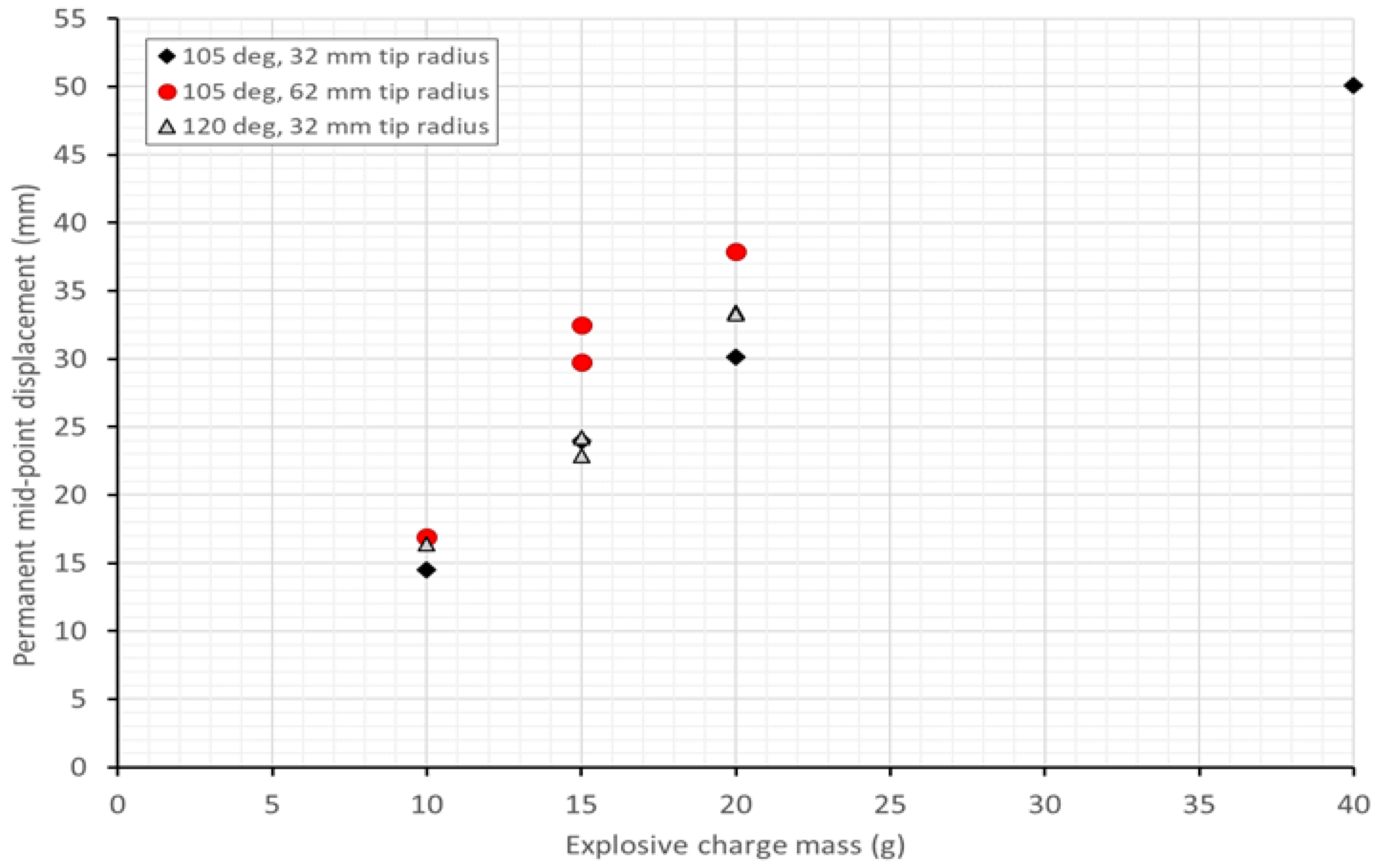
The influence of structural geometry on the permanent displacement is more clearly visible in the blast data. Figure 12 shows a graph of permanent mid-point versus charge mass. The 62 mm tip radius exhibited the largest displacement, despite the smaller internal angle, even when the overall impulse transfer was lower. The larger bend radius seems to produce a more flexible central region in the V-structure, whereas the tighter bend radius may be more work-hardened due to the cold bending process and may result in a more structurally rigid shape. Interestingly, the permanent displacement of the V-structure seemed more strongly influenced by the bend radius than the internal angle, and the impulse transfer seemed more affected by the internal angle.

3.3. Transient Response

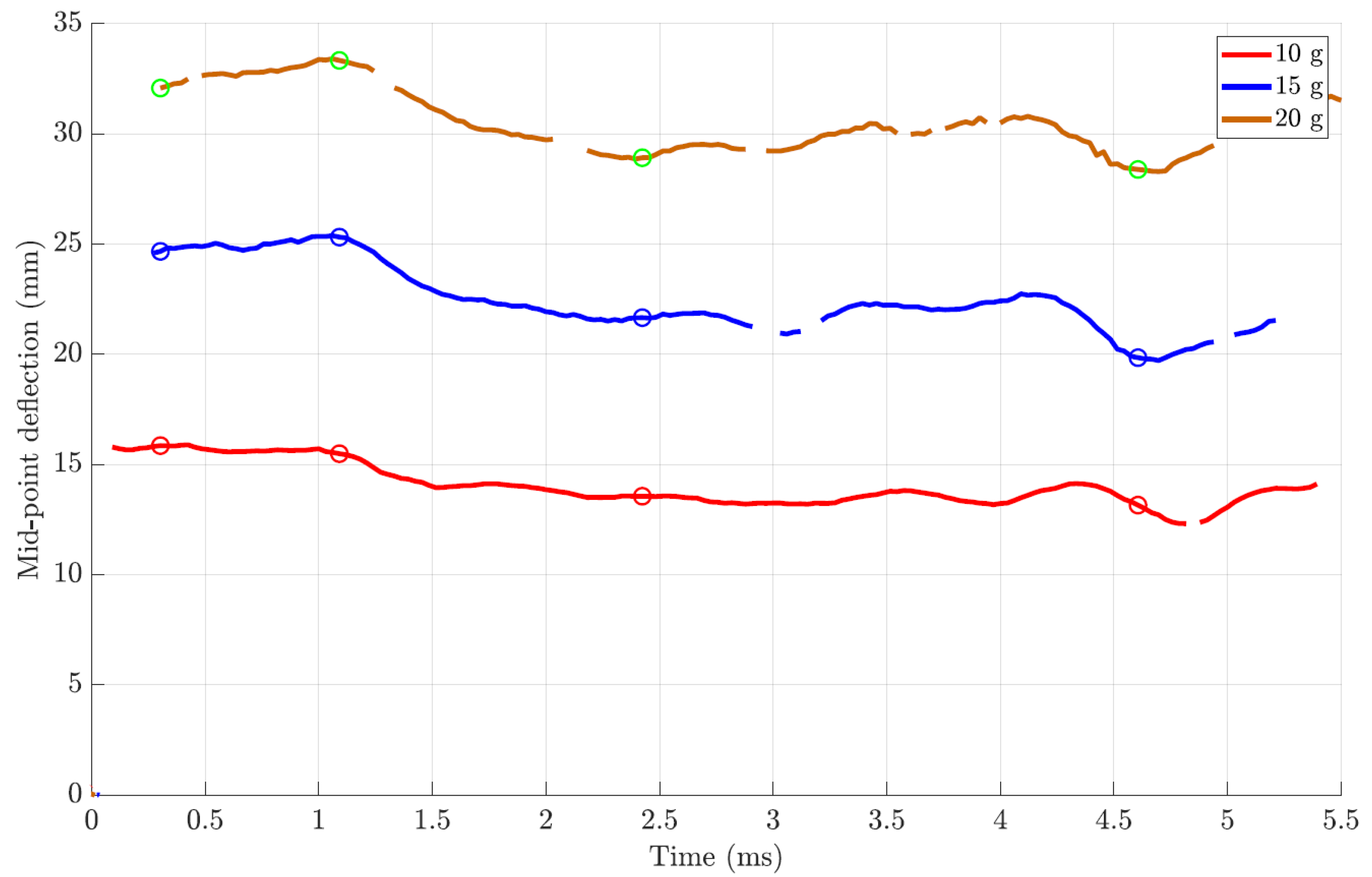
Transient mid-point displacement versus time data from the tests on 120° V-structures are shown in Figure 13. Unfortunately, the very early response (the first 0.1 ms) is missing due to motion blur in the images, which prevented clear displacement measurements. There are some small “gaps” in the post-peak vibration, which is evident in one of the 15 g detonations, caused by particulates obscuring the field of view for one of the cameras.
Despite these challenges, the peak displacements for each test were captured, occurring after approximately 1 ms. The rebound and post-peak elastic vibration phases were also evident. The difference between the peak and the permanent displacements was in the order of several plate thicknesses. The close similarity between the two 15 g detonations indicated good repeatability of the response.
Similar responses were obtained from the 105° V-structures, shown in Figure 14 and Figure 15: motion blur and obscuration caused similar gaps in the data. The gaps were more significant for 20 g detonations, probably due to the higher displacement magnitudes (and higher initial velocities). The 105° V-structures exhibited a less distinct peak displacement and lower rebounds, probably due to the difference in damage mode.
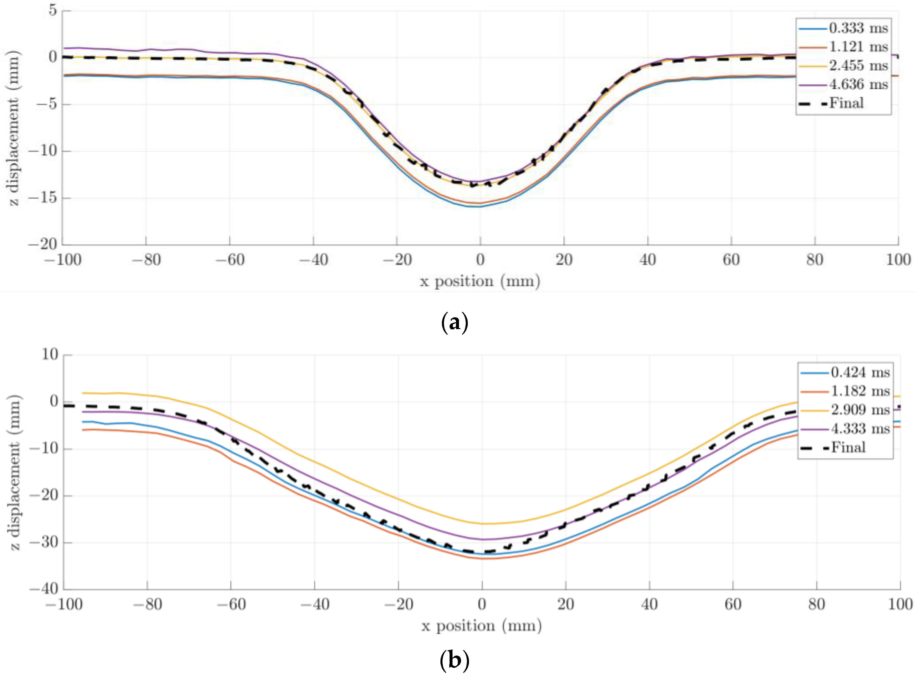
The transient displacement profiles along the ridge plane and the final deformed ridge profiles for selected 105° V structures are shown in Figure 16. The transient deformation along the ridge varied only in magnitude and not in shape for a given charge mass and V-structure type. The deformed region of the ridge increased with increasing charge mass, was higher for the larger internal angle (120° V structure), and was larger in the 105° V structures with the 62 mm tip radius than for the smaller tip radius of 32 mm.
The transient cross-cut response (not shown) was very similar to the permanently deformed profiles shown in Figure 8, Figure 9 and Figure 10, with small increases in out-of-plane displacement for increasing internal angle and tip radius. As expected, the transient displacement initially increased rapidly and then oscillated about the deformed displacement values.

4. Modelling Approach and Results

4.1. Computational Simulation Approach

To provide additional insight into the spatial impulse and transient behaviour of the structures, the tests were simulated using LS-Dyna R8 [31]. The model geometry is shown schematically in Figure 17. The V-structure, clamp frame, air block, and explosive were modelled using the multi-material arbitrary Lagrange–Eulerian (MMALE) fluid structure interaction (FSI) approach. The tests were modelled in quarter-symmetry using the same geometry of V-structure specimens and clamp frames as the physical experiment. A termination time of 300 µs was used, following previous work by the authors [4].
The V-structure was modelled using Lagrangian shell elements with a Belytschko-Tsay element formulation (ELFORM 2) and a Johnson Cook (MAT15) material model. The element size was set to 1.0 mm to best capture the curvature of the V-tip geometry and to ensure the best coupling with the Eulerian grid. Quasi-static uniaxial tensile tests were performed on samples from the Domex sheeting, following ASTM A370 [32]. Tests were performed at three engineering strain rates ( 10.4 × 10 4 , 41.6 × 10 4 , and 208.3 × 10 4   s 1 ). The results were used to obtain parameters for the Johnson–Cook material model [33] of A = 770 MPa, B = 420 MPa, n = 0.5 and c = 0.0009 at the reference strain rate of   10.4 × 10 4   s 1 , defined using the standard notation. A Taylor–Quinney coefficient of 0.9, a Poisson’s ratio of 0.33, a density of 7870 kg/m3 and a Young’s modulus of 210 GPa were assumed for the steel.
Based on previous work by the authors [4], the air was represented as a 200 mm by a 200 mm block (of varying height depending on the V-structure geometry) divided into 2 mm cubed elements, thereby minimising leakage forces and giving reasonable computational times. The volume of the explosive disc was discretised into elements that filled the air mesh using an initial volume fraction description with the detonation point placed 1 mm from the top of the explosive charge. The coupling between the explosive products and the test plate was modelled using a penalty-based approach.
The air was modelled using an ideal gas equation of state and a null material model. Boundary conditions were imposed on the symmetry boundaries, and all other surfaces of the air block were defined as free boundaries, allowing outflow of the Eulerian air formulation. The PE4 was modelled using the JWL equation of state and the high explosive burn material model, with the properties given in Table 1. Recent work by Bornstein et al. [34] on cylinder expansion tests showed that an inverse modelling approach for deriving JWL parameters for PE4 could lead to some improved fits with their experimental data, but to keep the simulations independent of the experiments herein, this approach was not adopted. Instead, the JWL parameters for PE4 were based on those commonly used for C4, following the same approach as Geretto [35] and Curry and Langdon [36].
The clamping frame and bolts were modelled with solid elements using a constant stress element formulation (ELFORM 1) with an elastic material model for mild steel. A plastic damage model was deemed unnecessary, as the clamp frame deflections were not observed to deform plastically during the experiments, but it was anticipated that the oscillation of the clamp frames influenced the measured transient deformation of the V-structures. The contact between the clamp frames and the V-structure was modelled with a surface-to-surface penalty contact approach.

4.2. Computational Simulation Results

LS-Dyna simulations provided additional insights into the transient responses of the panels, as the transient experimental measurements were limited due to motion blur, some correlation issues and degradation of the painted speckle pattern. Impulse transfer, transient mid-point displacement-time histories and deformed shapes were compared for the three experimental V-structures for the 10, 15 and 20 g charge mass detonations to validate the numerical approach. The impulse was under-estimated by 9–16% in the simulations, similarly to the under-predictions found by Chung Kim Yuen et al. [5]. The displacements were also slightly smaller in the simulations, perhaps due to the lower impulse transfer.
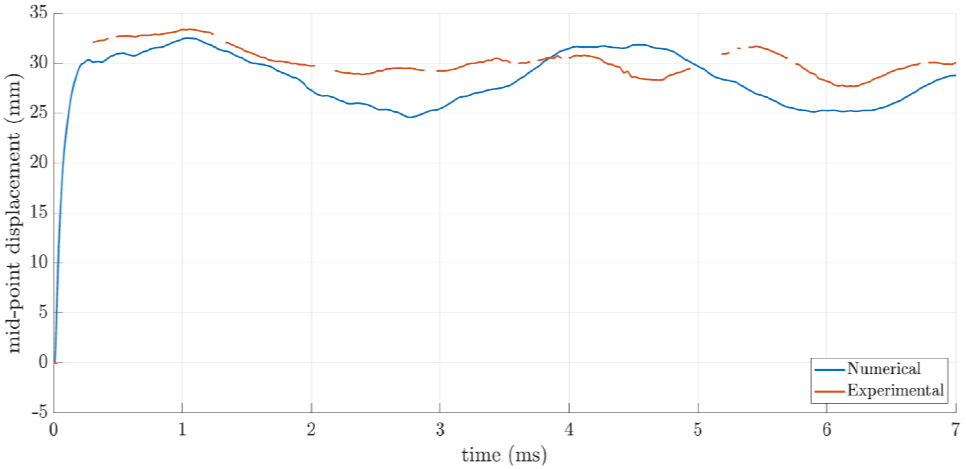
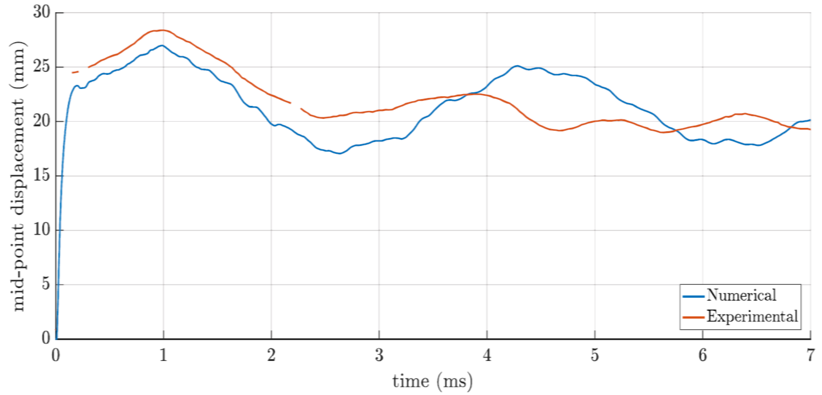
Some typical displacement-time histories from simulations are compared to their experimental equivalents in Figure 18 and Figure 19. The transient mid-point displacement evolution was similar, showing good agreement between the experimental and simulated peak mid-point displacements and permanently deformed profiles.

4.3. Response Characteristics of V-Structures Subjected to Localized Blast Loads

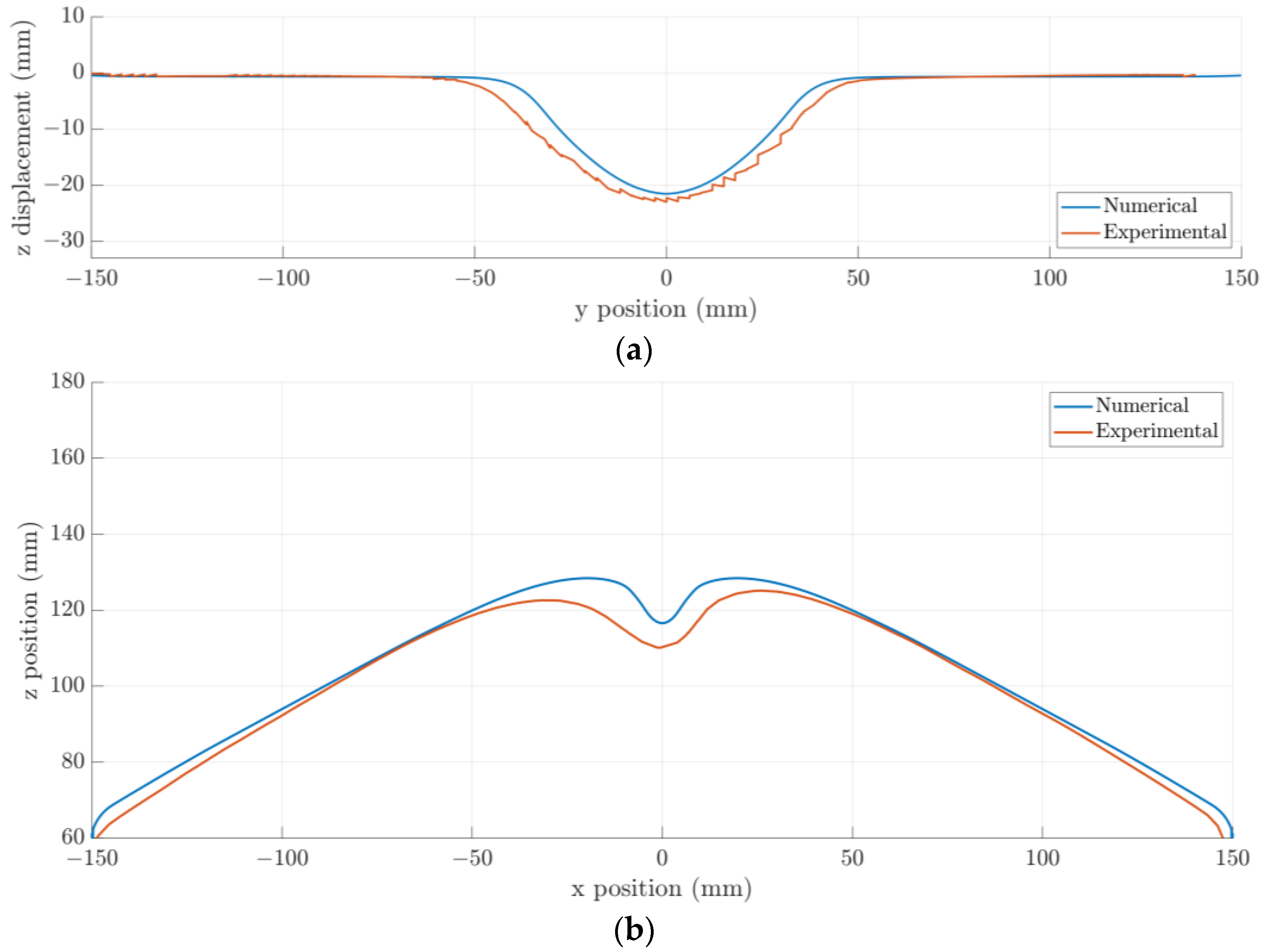
The same trends of increasing deformation (larger out-of-plane displacements and greater deformed areas) with increasing internal angle and increasing radius were present in the simulations, confirming the experimentally observed trends. The computational simulations predicted slightly more localized permanent deformation in both the ridge and crosscut profiles, as illustrated in Figure 20.
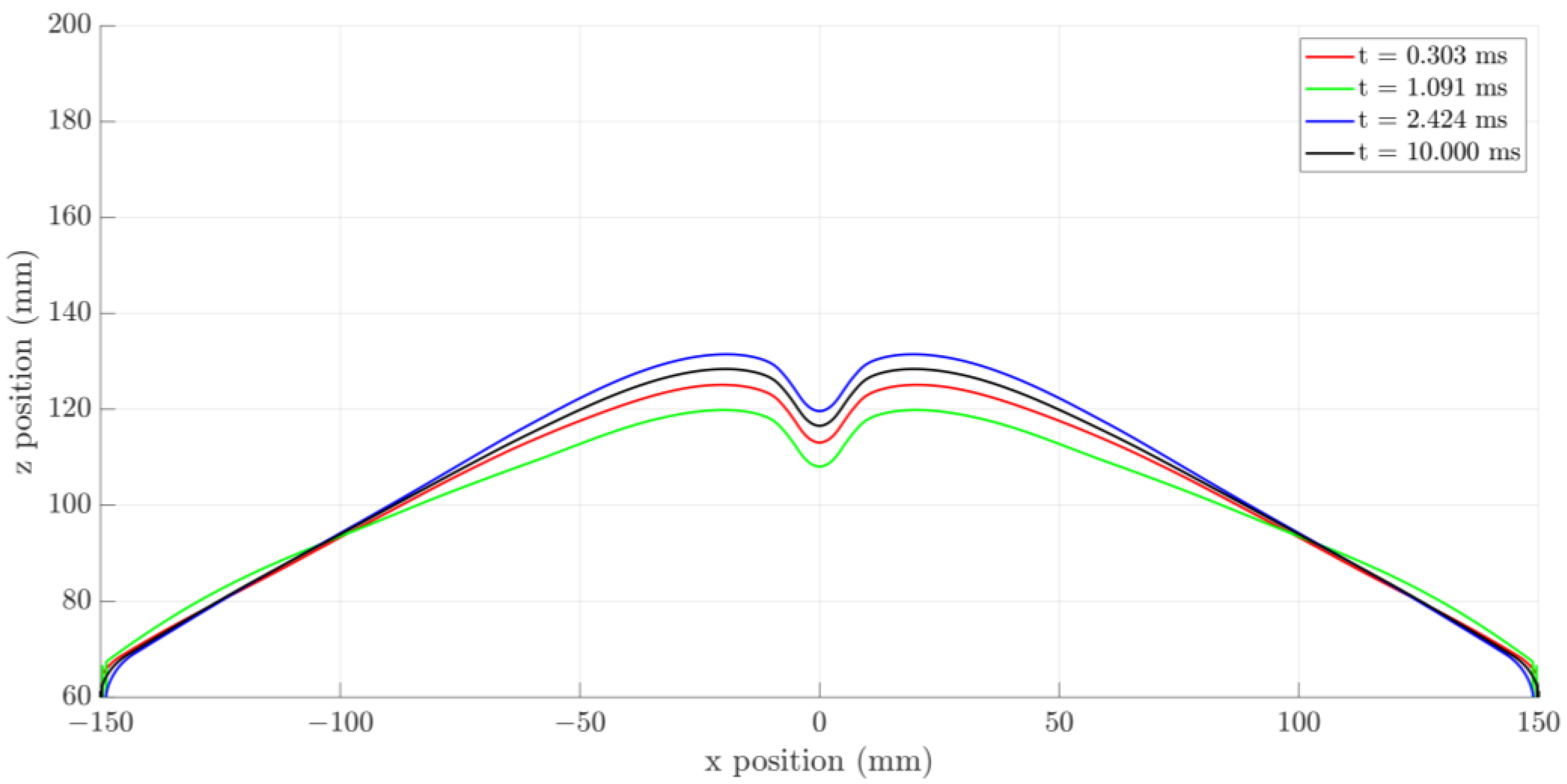
A typical set of transient deformation profiles from the computation simulations is shown in Figure 21 (in the crosscut direction). The discrepancy is more apparent in the crosscut profiles and is present in the transient predictions and the final deformed profile. The higher elastic recovery exhibited experimentally by the 120° V-structures (compared to the 105° V-structures) was also present in the simulations, confirming this is a feature of the geometric stiffness of the V-structures due to the internal angle.
The simulations were not able to reproduce the slight asymmetry in the panel response (observed most noticeably in the cross-cut direction) because they used a quarter-symmetry model. The small asymmetries in the structural response are attributed to the sensitivity of the buckling deformation mode to small variations, such as slight misalignment of the explosive charge relative to the centre of the structure and small variations in the V manufacturing (within the manufacturing tolerance but resulting in small variations in the ridge).

5. Conclusions

The experimental and numerical studies confirmed that the bend radius of the V-structure is an important parameter in the design of blast-mitigating V-hulls for MRAP vehicles. The current work showed that the larger tip-radii structures exhibit plastic deformation over a wider area than the previously tested structures with relatively sharp tips [4,5], in which a greater proportion of the ridge exhibited permanent deformation. Given that plate deflection is known to strongly correlate with energy-equivalent impulse [37], the experimental measurements confirmed the model’s predictions that the initial blast loading would be highly non-uniform and correlated with V-structure geometry.
None of the V-structures exhibited material rupture for the charge mass range considered, but work by Langdon et al. [38] showed for stiffened steel plates that areas of localized deformation are the regions that rupture more readily as charge mass increases. Thus, the regions of high deformation gradient (localized displacements) in the V-structures will be more prone to rupturing if the charge mass is increased beyond the range tested herein.
Increasing the tip radius while keeping the internal angle constant also increased the global impulse transfer to the V-structure, which may have a deleterious effect on passenger safety in practical use. One limitation of this study was the examination of only one stand-off distance, but the findings herein can be used as validation data for future simulation work of a greater range of threat scenarios (including off-centre blasts).
This study has implications for deployment of V-structures for blast protection—sharp-tipped V-structures will exhibit less permanent deformation but will be more prone to localized rupture in the areas that do deform, whereas structures with larger tip radii will need a larger region of the V-structure repaired after a blast event but may be less prone to rupture under highly localized blast loads. Given that a rupture would be catastrophic, there may be some optimization of a V-structured tip radius and internal angle required when assessing the range of threats for a deployed MRAP vehicle.

Author Contributions

Conceptualization, G.S.L. and C.J.v.K.; methodology, G.S.L., V.R.S. and C.J.v.K.; validation, V.R.S.; formal analysis, V.R.S.; investigation, V.R.S., G.S.L. and C.J.v.K.; resources, G.S.L.; data curation, V.R.S.; writing—original draft preparation, G.S.L. and V.R.S.; writing—review and editing, C.J.v.K.; supervision, G.S.L. and C.J.v.K.; project administration, G.S.L.; funding acquisition, G.S.L. All authors have read and agreed to the published version of the manuscript.

Funding

This research was funded by National Research Foundation of South Africa, grant number 111737. Opinions expressed and conclusions arrived at are those of the authors and are not necessarily to be attributed to the NRF.

Institutional Review Board Statement

Not applicable.

Informed Consent Statement

Not applicable.

Data Availability Statement

The data presented in this study are available on request from the corresponding author. The data are not publicly available due to this being part of an ongoing PhD study.

Acknowledgments

The authors are grateful to the UCT University Research Committee and to SSAB and Vulcan Steel for their donations of Domex steel. The authors would also like to thank the staff of the UCT Mechanical Engineering workshop for their assistance in machining the specimens and test consumables. Computations were performed using facilities provided by the University of Cape Town’s ICTS High Performance Computing team: https://ucthpc.uct.ac.za/ (last accessed on 10 December 2022).

Conflicts of Interest

The authors declare no conflict of interest.

References

  1. Army Technology, Cougar MRAP. 2021. Available online: https://www.army-technology.com/projects/cougar-mrap/ (accessed on 28 October 2022).
  2. Stiff, P. Taming the Landmine; Galago: Johannesburg, South Africa, 1986. [Google Scholar]
  3. US Department of Defense, Press Release, Washington, US, 14 October 2022. Available online: https://www.defense.gov/News/Releases/Release/Article/3189571/725-million-in-additional-security-assistance-for-ukraine/ (accessed on 28 October 2022).
  4. Shekhar, V.R.; Langdon, G.S. The effect of the bend radius on the impulse transfer characteristics of V-hulls: Numerical simulations. Int. J. Prot. Struct. 2020, 11, 69–89. [Google Scholar]
  5. Chung Kim Yuen, S.; Langdon, G.S.; Nurick, G.N.; Pickering, E.G.; Balden, V.H. Response of V-shape plates to localised blast load: Experiments and numerical simulation. Int. J. Impact Eng. 2012, 46, 97–109. [Google Scholar] [CrossRef]
  6. Pakulski, K.; Johnson, J.; Giffin, R.; Lo, M.; Wise, D.; St Onge, P.; Balcena, P.; Fridie, M.; Barrett, A. Prevention of Injury in Mine Resistant Ambush Protected (MRAP) Vehicle Accidents; US Army Aeromedical Research Laboratory Report No. 2013-14; US Army Aeromedical Research Laboratory: Fort Rucker, AL, USA, 2013. [Google Scholar]
  7. Ramasamy, A.; Hill, A.M.; Hepper, A.E.; Bull, A.M.J.; Clasper, J.C. Blast mines: Physics, injury mechanisms and vehicle protection. J. R. Army Med. Corps 2009, 155, 258–264. [Google Scholar] [CrossRef]
  8. Langdon, G.S.; Chung Kim Yuen, S.; Nurick, G.N.; Naidoo, K. Some insights into the response of ‘shallow V shape’ structures to air blast loading. Proc. Indian Natl. Sci. Acad. 2013, 79, 695–703. [Google Scholar] [CrossRef]
  9. Zhao, X.; Shultis, G.; Hurley, R.; Sutton, M.; Fourney, W.; Leiste, U.; Deng, X. Small scale models subjected to buried blast loading Part I: Floorboard accelerations and related passenger injury metrics with protective hulls. Exp. Mech. 2014, 54, 539–555. [Google Scholar] [CrossRef]
  10. Markose, A.; Rao, C.L. Mechanical response of V shaped plates under blast loading. Thin Walled Struct. 2017, 115, 12–20. [Google Scholar] [CrossRef]
  11. Follett, S. Blast Analysis of Composite V-Shaped Hulls: An Experimental and Numerical Approach. Ph.D. Thesis, Cranfield University, Cranfield, UK, 2012. [Google Scholar]
  12. Anderson, C.E., Jr.; Behner, T.; Weiss, C.E. Mine blast loading experiments. Int. J. Impact Eng. 2011, 38, 697–706. [Google Scholar] [CrossRef]
  13. Baranowski, P.; Malachowski, J. Numerical study of selected military vehicle chassis to blast loading in terms of tire strength improving. Bull. Pol. Acad. Sci. Tech. Sci. 2015, 63, 867–878. [Google Scholar] [CrossRef] [Green Version]
  14. Genson, K.W. Vehicle Shaping for Mine Blast Damage Reduction. Master’s Thesis, University of Maryland, College Park, MD, USA, 2006. [Google Scholar]
  15. Makwana, D.R.; Thakur, D.G.; Kangude, V.; Patil, B.S. Numerical evaluation and study of the effects of mine blast on V-hull of wheeled combat vehicle. Int. J. Recent Res. Asp. 2017, 4, 427–431. [Google Scholar]
  16. Sahu, R.R.; Gupta, P.K. Blast diffusion by different shapes of hull. Int. J. Automot. Eng. Tech. 2013, 2, 130–139. [Google Scholar]
  17. Trajkovski, J.; Kunc, R.; Prebil, I. Parametric analysis study of blast loaded armour V-plates. Int. J. Prot. Struct. 2017, 8, 524–538. [Google Scholar] [CrossRef]
  18. Trajkovski, J.; Kunc, R.; Prebil, I. Blast response of centrally and eccentrically loaded flat-, U-, and V-shaped armored plates: Comparative study. Shock Waves 2017, 27, 583–591. [Google Scholar] [CrossRef]
  19. Bucur, F.; Rotariu, A.; Trana, E.; Stefan, A. Experimental and numerical study on the mitigation capability of some special design structures. Int. J. Mod. Manuf. Technol. 2020, XII, 7–15. [Google Scholar]
  20. Johnson, T.E.; Basudhar, A. A metamodel-based shape optimization approach for shallow-buried blast-loaded flexible underbody targets. Int. J. Impact Eng. 2015, 75, 229–240. [Google Scholar] [CrossRef]
  21. Kamal, H. Studying the trade-off between protection and mobility of armored vehicles. In Proceedings of the ASME 2017 International Mechanical Engineering Congress and Exposition, Tampa, FL, USA, 3–9 November 2017. IMECE2017-72531. [Google Scholar]
  22. Trajkovski, J.; Perenda, J.; Kunc, R. Blast response of light armored vehicles (LAVs) with flat and V-hull floor. Thin Walled Struct. 2018, 131, 238–244. [Google Scholar] [CrossRef]
  23. Langdon, G.S.; Curry, A.; Siddiqui, A. Improving the impulse transfer and response characteristics of explosion loaded compound V-plates. Thin Walled Struct. 2020, 148, 106609. [Google Scholar] [CrossRef]
  24. Langdon, G.S.; Curry, A.; Shekhar, V.R.; Siddiqui, A.; Murray, C.; von Klemperer, C.J. Attempts to improve on the V-hull structural design for air-blast loading applications. Ce/Papers 2021, 4, 1499–1506. [Google Scholar] [CrossRef]
  25. Stanislawek, S.; Morka, A. On the blast mitigation ability of multiple V-shape deflectors. Shock. Vib. 2020, 2020, 8708974. [Google Scholar] [CrossRef]
  26. Cong, M.; Yun-bo, Z.; Ming, Z.; Xiao-wang, S.; Cheng, C.; Cheng, J. Design and optimization of multi-V hulls of light armoured vehicles under blast loads. Thin Walled Struct. 2021, 168, 108311. [Google Scholar] [CrossRef]
  27. Erdik, A. Experimental and numerical study on dynamic response of V-shaped hull subjected to mine blast. Mech. Based Des. Struct. Mach. 2020, 50, 707–725. [Google Scholar] [CrossRef]
  28. Mehreganian, N.; Louca, L.A.; Langdon, G.S.; Curry, R.J.; Abdul-Karim, N. The response of mild steel and armour steel plates to localised air-blast loading—Comparison of numerical modelling techniques. Int. J. Impact Eng. 2018, 115, 81–93. [Google Scholar] [CrossRef]
  29. Langdon, G.S.; Gabriel, S.; von Klemperer, C.J.; Chung Kim Yuen, S. Transient response and failure of medium density fibreboard panels subjected to air-blast loading. Compos. Struct. 2021, 273, 114253. [Google Scholar] [CrossRef]
  30. Curry, R.J.; Langdon, G.S. Transient response of steel plates subjected to close proximity explosive detonations in air. Int. J. Impact Eng. 2017, 102, 102–116. [Google Scholar] [CrossRef]
  31. LS Dyna, Ansys. Available online: https://www.dynasupport.com/manuals (accessed on 15 June 2021).
  32. Geretto, C. The Effects of Different Degrees of Confinement on the Deformation of Square Plates Bubjected to Blast Loading. Ph.D. Thesis, University of Cape Town, Cape Town, South Africa, 2012. [Google Scholar]
  33. Johnson, G.R.; Cook, W.H. Fracture characteristics of three metals subjected to various strains, strain rates, temperatures and pressures. Eng. Fract. Mech. 1985, 21, 31–48. [Google Scholar] [CrossRef]
  34. Bornstein, H.; Kuznetsov, V.; Lu, J.-P.; Stojko, S.; Freundt, J. Characterising and validation of the JWL equation of state parameters for PE4. Int. J. Impact Eng. 2022, 164, 104190. [Google Scholar] [CrossRef]
  35. ASTM A370-17; Standard Test Methods and Definitions for Mechanical Testing of Steel Products. ASTM International: West Conshohocken, PA, USA, 2017.
  36. Curry, R.J.; Langdon, G.S. The effect of explosive charge backing in close-proximity air-blast loading. Int. J. Impact Eng. 2021, 151, 103822. [Google Scholar] [CrossRef]
  37. Rigby, S.E.; Akintaro, O.I.; Fuller, B.J.; Langdon, G.S.; Pope, D.J. Predicting the response of plates subjected to near-field explosions using an energy equivalent impulse. Int. J. Impact Eng. 2019, 128, 24–36. [Google Scholar] [CrossRef]
  38. Langdon, G.S.; Chung Kim Yuen, S.; Nurick, G.N. Experimental and numerical studies on the response of quadrangular stiffened plates, Part II—Localised blast loading. Int. J. Impact Eng. 2005, 31, 85–111. [Google Scholar] [CrossRef]
Figure 1. Side profile of a 2 mm thick V-structure with a 105° internal angle with an external tip radius of 32 mm, i.e., a bend radius = 30 mm (dimensions are in mm).
Applsci 13 01293 g001
Figure 2. Schematic showing the clamping system and sealing plates along the edges of the V-structure.
Applsci 13 01293 g002
Figure 3. Photograph of the blast test arrangement, showing the V-structure specimen, mounting frame and pendulum system, prior to testing.
Applsci 13 01293 g003
Figure 4. Photograph showing the white/black speckle pattern on the rear surface of the V-structure.
Applsci 13 01293 g004
Figure 5. Photograph showing permanent damage in the central region of a blast-tested 120° V-structure (32 mm tip radius, tested at 20 g).
Applsci 13 01293 g005
Figure 6. Photographs showing the top view a blast-tested 105° V-structure, 32 mm tip radius, with localised permanent deformation along the central ridge: (a) tested at 10 g, (b) tested at 40 g.
Applsci 13 01293 g006
Figure 7. 3D profiles of blast tested V-structures (105° internal angle, 32 mm tip radius) tested at (a) 10 g, (b) 15 g, (c) 20 g and (d) 40 g.
Applsci 13 01293 g007aApplsci 13 01293 g007b
Figure 8. Permanently deformed profiles of blast tested V-structures (105° internal angle, 32 mm tip radius) of the (a) ridge plane, (b) cross-cut plane.
Applsci 13 01293 g008
Figure 9. Permanently deformed profiles of blast tested V-structures (105° internal angle, 62 mm tip radius) of the (a) ridge plane, (b) cross-cut plane.
Applsci 13 01293 g009
Figure 10. Permanently deformed profiles of blast tested V-structures (120° internal angle, 32 mm tip radius) of the (a) ridge plane, (b) cross-cut plane.
Applsci 13 01293 g010aApplsci 13 01293 g010b
Figure 11. Graph of impulse transfer versus charge mass obtained from the blast test data.
Applsci 13 01293 g011
Figure 12. Graph of permanent midpoint displacement vs. charge mass obtained from the blast tests.
Applsci 13 01293 g012
Figure 13. Graph of transient midpoint displacement vs. time obtained from blast tests on 120° V-structures, 32 mm tip radii. Circles indicate the discrete times for the selected deformation profiles.
Applsci 13 01293 g013
Figure 14. Graph of transient midpoint displacement versus time obtained from the blast tests on 105° V-structures with a 32 mm tip radius.
Applsci 13 01293 g014
Figure 15. Graph of transient midpoint displacement versus time obtained from the blast tests on 105° V-structures with 62 mm tip radii (circles indicate the discrete times for the selected deformation profiles).
Applsci 13 01293 g015
Figure 16. Transient deformation profiles at discrete times, along with a ridge, in 105° V-structures with (a) 10 g PE4, 32 mm tip radius, (b) 15 g PE4, 62 mm tip radius.
Applsci 13 01293 g016
Figure 17. Schematic showing the computational model.
Applsci 13 01293 g017
Figure 18. Graph of transient midpoint displacement versus time for a 105° V-structure with a 32 mm tip radius subjected to a 20 g detonation, comparing experimental and simulated data.
Applsci 13 01293 g018
Figure 19. Graph of transient midpoint displacement versus time for a 120° V-structure with a 32 mm tip radius subjected to a 15 g detonation, comparing experimental and simulated data.
Applsci 13 01293 g019
Figure 20. Final deformed profiles for V-structures subjected to blast, comparing experimental results with computational simulations: (a) 105° V, 32 mm tip radius, 15 g detonation, ridge profile; (b) 120° V, 32 mm tip radius, 20 g detonation, cross-cut profile.
Applsci 13 01293 g020
Figure 21. Simulated transient crosscut deformed profiles for a 120° V structure, 32 mm tip radius, subjected to a 20 g detonation.
Applsci 13 01293 g021
Table 1. Properties of PE4 used in the computational simulations [34,35].
ρ0
(kg/m3)
D
(m/s)
PCJ
(GPa)
A
(GPa)
B
(GPa)
R1R2ωE0
(GPa)
1616819328609.7712.954.51.40.259
Disclaimer/Publisher’s Note: The statements, opinions and data contained in all publications are solely those of the individual author(s) and contributor(s) and not of MDPI and/or the editor(s). MDPI and/or the editor(s) disclaim responsibility for any injury to people or property resulting from any ideas, methods, instructions or products referred to in the content.