Abstract
Compared with the traditional needle driving method, hybrid maglev needle driving is a new weft knitting machine technology, which alleviates the problems of noise, heat, and needle breakage. However, in the structure of needle arrays, magnetic disturbance between permanent magnet knitting needles leads to unstable needle control. Therefore, this paper attempts to solve this problem through a performance analysis of hybrid maglev needle driving. Based on the structure, the magnetic force distribution model of permanent magnet knitting needles is established. Aiming at the magnetic interference between magnetic arrays, a magnetic shielding material, silicon steel with a high permeability, is proposed to optimize the driving structure of a magnetic levitation needle array. Through simulation and experimental analysis, the influence of different silicon steel thicknesses on magnetic field shielding is analyzed. It is concluded that the optimal value of a silicon steel sheet is 1 mm and that the optimal gauge of hybrid maglev knitting needles is 8 mm. Finally, compared with the theoretical and simulation analysis, the experimental results have indicated that the proposed optimized structure of the gauge of hybrid maglev knitting needles is correct and effective.
1. Introduction
The computerized flat knitting machine is a very important textile equipment in the textile industry, mainly used for knitting sweaters and medical textiles. The needle drive system is an important part of it, which is related to the quality of textiles [1]. The traditional knitting machine uses a cam inside the machine head to push the needle in the needle slot to complete the knitting process [2]. During the operation of the equipment, the heel of the knitting needle often breaks due to poor lubrication, which in turn affects the quality of the fabric. In addition, the traditional cam drive needle has problems, such as vibration, noise, heating and wear. Therefore, some researchers have proposed a hybrid magnetic levitation needle array drive structure [3,4,5]. Hybrid magnetic levitation is a hybrid electromagnetic and permanent magnetic structure, which used an electric coil to generate an electromagnetic field. The repulsive force generated by the electromagnetic field and permanent magnet suspends the knitting needle. This structure can avoid the collision caused by mechanical transmission, so as to eliminate the related vibration, noise, and wear. However, the existing structure also has some defects. For example, when a hybrid magnetically levitated needle is driven, the spatial magnetic fields between the permanent magnet needles interfere with each other [6]. The smaller the gauge of the permanent magnet needle, the greater the magnetic disturbance; therefore, the permanent magnet needle drive cannot be stably controlled.
Magnetic field interference situations are common in electronic devices [7,8]. This can lead to energy loss, electromagnetic radiation, equipment that is difficult to control, etc. Shielding is the key to solving magnetic field interference [9,10]. Magnetic field shielding is used in a wide range of applications, such as transmission circuits, electric vehicles, electronic components, and aerospace [11]. At present, with the development of material technology, some nano-materials with magnetic field shielding characteristics have been developed [12,13,14]. Woven products with electromagnetic shielding effects have also been developed in the textile field [15]. However, the cost of these materials is high.
The driving structure of a hybrid magnetic levitation needle array has small needle spacing and a large number, which challenges the structural optimization of avoiding excessive magnetic interference between permanent magnetic needles. In this paper, through the analysis of the driving performance of a magnetic levitation needle array, the driving structure of the magnetic levitation needle array is optimized by using silicon steel, a high-permeability material, as the shielding material of the magnetic field. This material has the advantages of a low core loss, high magnetic induction strength, good insulating film performance, and low price. Finite element and experimental methods are used to analyze the effect of different silicon steel thicknesses on magnetic field shielding. The research results are of great significance in terms of enriching the design results of magnetic levitation needle array drive structures and proposing a more reasonable magnetic levitation needle array drive structure. The results of this paper can also provide a reference for the design of other similar projects.
2. Driving Structure of Hybrid Maglev Needle
Hybrid magnetic levitation involves exerting a magnetic levitation force on the permanent magnet knitting needle through the interaction between the electromagnetic coil and the permanent magnet. As shown in Figure 1, the hybrid maglev needle array drive consists of two parts. The upper part is a needle plate. It is composed of permanent magnet needles (the permanent magnet and needle are an integrated structure), a needle slot, a partition and silicon steel sheets. The lower part is the flat knitting machine head. It is composed of a coil, aluminum skeleton and iron core. The electromagnetic coil is set with different magnitudes of current to produce electromagnetic fields of different intensities. The electromagnetic field interacts with the magnetic field of the permanent magnet. According to the principle of same-sex repulsion and opposite-sex attraction, when different sizes of levitation and attraction are exerted on the permanent magnetic knitting needles, the permanent magnetic knitting needles can be displaced to different heights in the needle slot. The head of the flat knitting machine moves through the synchronous belt. During the process of the head movement, the knitting acts in accordance with the knitting processes. In this way, the action of the weaving process is realized [5].
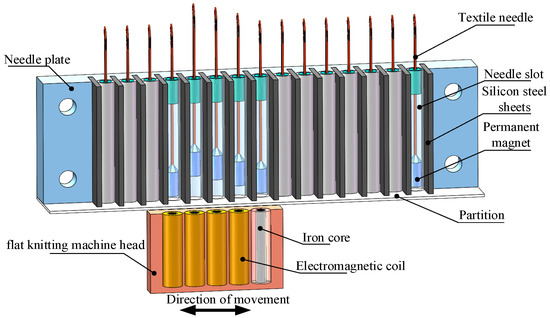
Figure 1.
Driving structure diagram of hybrid maglev needle array.
3. Performance Analysis of Hybrid Maglev Needle Drive
3.1. Mathematical Model of the Magnetic Force for Knitting Needle Gauge
In the structure of the needle plate, the close arrangement of the permanent magnet needles leads to magnetic disturbance forces between the permanent magnets. One needle is driven by an electromagnet, and the adjacent needles follow the moving needle. It is very difficult to control every needle independently. In order to study the magnetic disturbance between permanent magnet knitting needles, the disturbance force between permanent magnet knitting needles is simplified to the magnetic disturbance force between permanent magnets [16]. On the basis of the magnetic dipole method, the simplified magnetic force model of a permanent magnet needle can be obtained as shown in Figure 2.
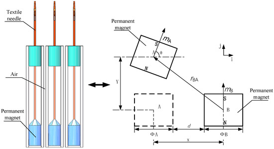
Figure 2.
Simplified model of interaction between two permanent magnet needles.
The magnetic flux density generated by B at A is:
where is the vacuum permeability, is the vector gradient, and are the magnetic moments of the permanent magnet, and is the direction vector from the permanent magnet B to permanent magnet A. , and are, respectively, expressed as:
where and are the magnetization of the permanent magnet, and are the volume of the permanent magnet, is the deflection angle of the permanent magnet A, is the center distance between the permanent magnet A and permanent magnet B, is the vertical distance between the permanent magnet A and permanent magnet B, and and are vector coordinates. The potential energy between two permanent magnets is:
Substituting Equations (1)–(4) into Equation (5) results in:
According to Equation (6), the smaller the center distance and vertical distance between the two permanent magnets, the greater the magnetic potential between the two permanent magnets. The deflection angle caused by the movement of the permanent magnet needle in the needle slot is 90°. When . Therefore, Equation (6) can be simplified as:
Based on Equation (7), the magnetic force of mutual interference between permanent magnetic needles is:
The relationship between residual magnetic induction and residual magnetization meets the following requirements:
Equation (8) is transformed into:
According to Equation (10), the magnetic force between permanent magnets is inversely proportional to the Fourth Square of the center distance of permanent magnet needles. A dense needle pitch will produce a large interference magnetic force.
3.2. Validation of Mathematical Models
We verified the correctness of the mathematical model of the magnetic force of the knitting needle gauge.
According to the structure, the parameters of the maglev weft needle system are shown in Table 1. Using finite element simulation software and mathematical analysis software to analyze the model, the comparison of the results is shown in Figure 3.

Table 1.
Parameters related to permanent magnets and silicon steel sheets.
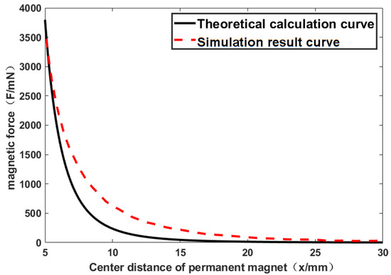
Figure 3.
Comparison of theoretical and simulated curves of permanent magnet center distance and magnetic force.
Figure 3 shows the change trend of the magnetic force curve through theoretical calculation and simulation analysis. Obviously, the result calculated via formula 10 is highly consistent with the simulation analysis. When the permanent magnetic needles are closely arranged, a large magnetic interference will be generated. In this case, the driving of the needle has an effect on the adjacent needles. When the gauge of the knitting needles increases, the magnetic force between the permanent magnet needles will reduce. However, the increased gauge will decrease the fabric density, which will reduce the types of fabric through this machine.
4. Optimization of Hybrid Maglev Needle Drive
If there are more kinds of fabric on the magnetic suspension flat knitting machine, it is necessary to have a tighter needle distribution. This means a smaller gauge for the knitting needles should be used. However, the close proximity of the needles creates a magnetic interference with each other, which prevents the electromagnetic coil from providing a stable drive control of the permanent magnet needles.
4.1. Structural Optimization of Hybrid Maglev Needle Drive
In order to solve this problem, a scheme is proposed. A silicon steel sheet is inserted between adjacent permanent magnet needles. According to the high permeability of silicon steel, the magnetic field of the permanent magnet is confined between two pieces of silicon steel. The simplified model is shown in Figure 4.
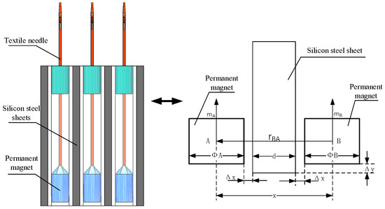
Figure 4.
Simplified model of silicon steel magnetic isolation.
As can be seen in Figure 4, the silicon steel sheet with a certain thickness is inserted between the permanent magnets, and the high permeability of silicon steel shrinks the magnetic field between permanent magnets. Equation (10) is transformed into:
where is the permeability of silicon steel, is the thickness of silicon steel, and is the thickness of the needle slot.
From Figure 4, it can be concluded that the gauge for the hybrid maglev needle is:
4.2. Magnetic Force Change of Knitting Needle Gauge with Silicon Steel Shield
Figure 5 shows the trend of the magnetic force curve obtained by theoretical calculation and simulation analysis after adding the silicon steel sheet. It is obvious that the results calculated from Equation (11) are highly consistent with the simulation analysis. As can be seen in Figure 5, the addition of a certain thickness of silicon steel sheet reduces the magnetic disturbance between the permanent magnets to a very low value. When the magnetic disturbance between the permanent magnets reaches a low value, the electromagnetic coil drives the motion of the permanent magnet needle without a jittering or deflection of the adjacent permanent magnet needle. The movement of the permanent magnet needle does not affect adjacent permanent magnet needles, allowing for an independent and stable control of the permanent magnet needle.
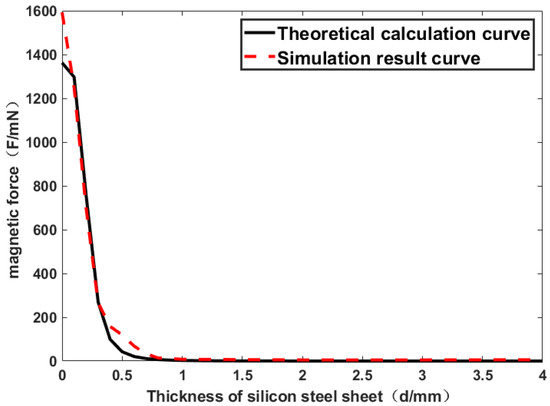
Figure 5.
Comparison of theoretical and simulated curves of silicon steel thickness and magnetic force.
Comparing Figure 3 with Figure 5, without the addition of silicon steel sheet, a large spacing between permanent magnet needles is required to minimize interfering magnetic forces. With the addition of silicon steel sheets, the permanent magnet needles minimize interference magnetism at a smaller pitch. The theory and simulation show that inserting a silicon steel sheet between permanent magnetic needles can effectively reduce the magnetic force interference between permanent magnetic needles, so as to obtain the optimal structure of the gauge of the hybrid maglev needle.
Permanent magnets generate magnetic force, which attracts the silicon steel sheet. As shown in Figure 6, the magnetic attraction produced by the permanent magnet and the silicon steel sheet on the right side is F1, and that on the left side is F2. Because of the overall drive structure being an axisymmetric structure, the distance between the permanent magnet in the center and the permanent magnet on both sides of the silicon steel sheet is equal. Thus, F1 = F2, and the horizontal magnetic field of the permanent magnet is in equilibrium. The electromagnetic driving force F0 determines the upward motion of the permanent magnet.
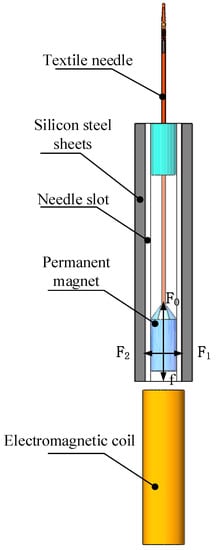
Figure 6.
Needle drive structure diagram.
According to the parameters in Table 1 and Table 2, the model was analyzed by using simulation software. The driving force on the permanent magnet increases with the increase of current. As shown in Figure 7, with the addition of the silicon steel structure, the permanent magnet is subjected to little change in the driving force. Thus, F0 is not affected.
Table 2.
Parameter table of electromagnetic coil.
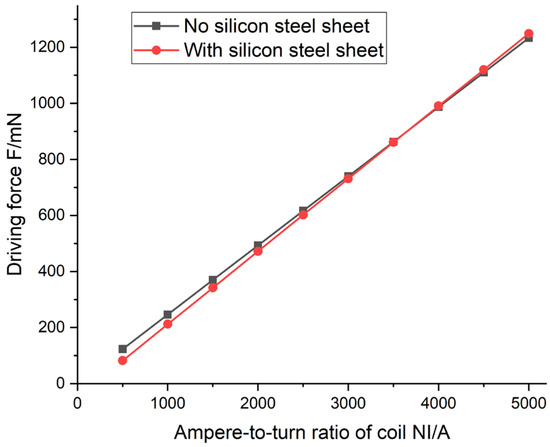
Figure 7.
Graph of electromagnetic drive force.
The interaction force between the permanent magnet and the silicon steel increases the resistance f of the permanent magnet during the movement. Because of the symmetrical structure of the silicon steel, the magnetic field of the permanent magnet is in equilibrium, and this resistance is not very high. This effect can be avoided by increasing the current appropriately.
4.3. Analysis of Silicon Steel Thickness and Magnetic Field Shielding
The magnetic levitation flat knitting machine has arrays of permanent magnetic needles in the needle plate. To investigate the feasibility of silicon steel sheets in permanent magnet array structures, according to the parameters in Table 1 and Table 3, the hybrid maglev needle array was modeled by using finite element simulation software.
Table 3.
Parameters of the array.
From Figure 8, it can be concluded that the magnetic interference force to the permanent magnet in the permanent magnet array decreases with the increase of the thickness of the silicon steel sheet, which verifies the ability of the silicon steel sheet in the permanent magnet array structure to reduce the interference of the permanent magnet.
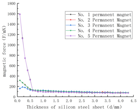
Figure 8.
Variation curve of permanent magnet stress with silicon steel thickness.
When the thickness of the silicon steel sheet is d < 1 mm, the No. 1 and No. 5 permanent magnets at both ends will be magnetically attracted to the middle of the permanent magnet array, and their magnetic force values are larger; meanwhile, the middle permanent magnet will be attracted by the common magnetic force of the two adjacent permanent magnets due to its symmetrical structure, and its magnetic force values are smaller compared to the No. 1 and No. 5 permanent magnets at both ends. When the thickness of the silicon steel sheet is d ≥ 1 mm, the magnetic interference force of the permanent magnet array is effectively reduced by the excitation of the silicon steel, so that the magnetic interference force of the permanent magnet array tends to be consistent, and the magnetic force value is low.
To verify the change of magnetic field after optimizing the structure, a magnetic field analysis of the optimized structure is performed by using finite element simulation software.
From Figure 9a,b, it can be seen that the magnetic fields between the permanent magnet arrays without the addition of silicon steel sheets interfere with each other, so that the displacement of one of the permanent magnets will lead to the mutual interference of the magnetic fields of the other permanent magnets, and the motion control of a single permanent magnet cannot be achieved without affecting the other permanent magnets. Figure 9c shows that after inserting silicon steel sheets between the permanent magnets, the magnetic fields of the permanent magnets are concentrated inside their respective pin slots, and the interference between the magnetic fields overflowing at the bottom of the permanent magnet array is extremely small. The interaction of the permanent magnets is extremely low, and motion control of a single permanent magnet can be achieved without affecting the other permanent magnets. Silicon steel is a material with a high permeability, and one can see from Figure 9d that the permanent magnet will generate a certain magnetic induction strength inside the silicon steel, which will lead to the mutual attraction of the permanent magnet and the silicon steel. Because of the symmetrical structure of the silicon steel, the magnetic field of the permanent magnet is in equilibrium, and this resistance is not very high. The silicon steel sheet construction does not affect the needle drive control.
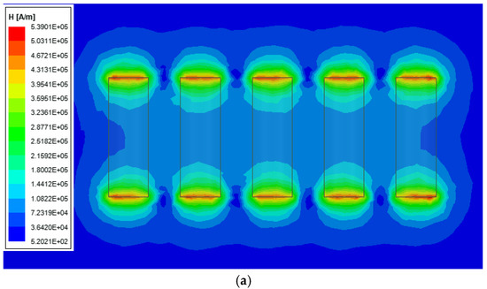
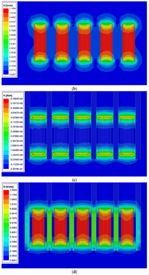
Figure 9.
Magnetic field simulation results. (a) Cloud diagram of magnetic field distribution of permanent magnet array. (b) Cloud diagram of magnetic induction distribution of permanent magnet array. (c) Cloud diagram of magnetic field distribution of permanent magnet silicon steel array. (d) Cloud diagram of magnetic induction distribution of permanent magnet silicon steel array.
The comparison of the magnetic interference of the permanent magnet array is derived from the simulation results in Figure 9. The specific values are shown in Table 4. One can see that in the case of an 8 mm needle distance, the permanent magnet without a silicon steel sheet is greatly affected by the adjacent permanent magnet, and the influence between the permanent magnets is minimal after the silicon steel sheet with a 1 mm thickness is added. Therefore, the electromagnetic coil enables stable control of each needle.
Table 4.
Comparison of simulation results.
5. Experimental Verification
To verify the effectiveness of the optimized structure of the hybrid maglev weft knitting needle, an experimental setup was designed and built, as shown in Figure 10. The CH3600 high-precision Gauss meter made by Beijing Cuihai Science and Trade Co., Ltd. in Beijing, China, is used to measure the magnetic induction intensity of permanent magnetic needles at different distances, which can reflect the magnetic interference between permanent magnetic needles.
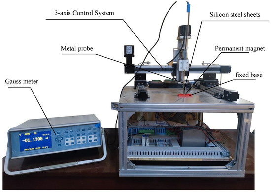
Figure 10.
Experiments with maglev weft knitting needles.
The decreasing trend of magnetic induction in Figure 11 can verify the correctness of the magnetic force trend in Figure 3. Furthermore, the experiment also shows that at smaller center distances of the needles, the magnetic induction strength between the permanent magnet needles is larger, which generates stronger magnetic field disturbances and thus interferes with the stability of the needle drive.
Figure 11.
Transverse magnetic induction intensity of permanent magnet knitting needle.
The decreasing trend of magnetic induction in Figure 12 can verify the correctness of the magnetic force trend in Figure 5. The experimental data verified the effectiveness of the structure. When the thickness of the silicon steel sheet reaches 1 mm, there is a significant reduction in the magnetic field. When the gauge of the magnetic levitation needle flat knitting machine is 8 mm, the magnetic field interference between permanent magnet needles reaches the requirement of a stable control.
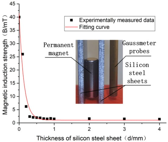
Figure 12.
Variation curve of magnetic induction intensity with silicon steel thickness.
In order to test the practicality of the structural design, an experimental platform for a hybrid magnetic levitation needle drive was built, as shown in Figure 13. With the addition of silicon steel sheets, the disturbing magnetic force between the permanent magnet knitting needles was shielded. The electromagnetic coil can drive the permanent magnets up to different heights without affecting the drive of adjacent permanent magnets. Each permanent magnet needle can control the movement independently. Therefore, the design of this paper is practical.
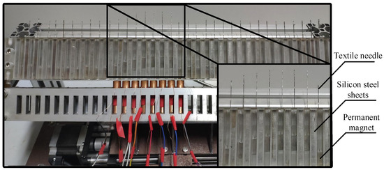
Figure 13.
The driving effect of the hybrid maglev needle.
6. Conclusions
During the driving process of the hybrid magnetic levitation needle, the magnetic field interference between the two needles leads to the instability of the needle control. This paper analyzes the magnetic disturbance phenomenon when permanent magnets of the same magnetizing direction are arranged in an array. The structure involving the insertion of a silicon steel sheet between permanent magnets is designed to reduce magnetic disturbance. Through simulation analysis and experimental measurement, it is concluded that the optimal thickness of a silicon steel sheet for shielding is 1 mm. Under this condition, the magnetic disturbance between permanent magnetic needles is at a minimum. Additionally, the optimal gauge of hybrid maglev knitting needles is 8 mm, which can effectively reduce magnetic leakage. The optimized hybrid maglev weft knitting machine enables an independent and stable control of the needle at small gauges. This research work provides a reference for the design of hybrid maglev weft knitting machines.
Author Contributions
All authors contributed to this work. Conceptualization, T.X. and Y.P.; methodology, T.X. and X.Z.; software and funding acquisition, C.Z. (Chengjun Zhang) and X.Z.; validation, C.Z. (Chi Zhang) and L.Z.; data curation, T.X. and Y.P.; supervision, C.Z. (Chengjun Zhang) and H.L.; writing—original draft, T.X. All authors have read and agreed to the published version of the manuscript.
Funding
The authors acknowledge the financial support from National Natural Science Foundation of China (51875414); Science and Technology Research Project of the Department of Education of Hubei Province (D20211705).
Institutional Review Board Statement
Not applicable.
Informed Consent Statement
Not applicable.
Data Availability Statement
Not applicable.
Conflicts of Interest
The authors declare no conflict of interest.
References
- He, Z.; Xu, J.; Tran, K.P.; Thomassey, S.; Zeng, X.; Yi, C. Modeling of textile manufacturing processes using intelligent techniques: A review. Int. J. Adv. Manuf. Technol. 2021, 116, 39–67. [Google Scholar] [CrossRef]
- Zhao, C.; Song, G.L.; Xu, L. Optimal Design of Computerized Flat Knitting Machine Cam Curves Based on UG and ANSYS/LS-DYNA. Appl. Mech. Mater. 2014, 529, 410–414. [Google Scholar] [CrossRef]
- Liu, Z.; Xu, G. Design and simulation of Lorentz force actuated maglev knitting needle actuator. J. Text. Res. 2021, 42, 159–165. [Google Scholar]
- Xiong, T.; Yin, W.; Li, D.; Zhang, C.; Zuo, X. Research on Electromagnetic Force of Hybrid Electromagnetic Levitation Needle Driving System. In Proceedings of the International Conference on Electronics, Electrical and Information Engineering 2021, ICEEIE 2021, Changsha, China, 13–16 August 2021; Volume 2136. [Google Scholar]
- Zuo, X.; Zhang, C.; Xiong, T.; Yin, W.; Li, M.; Zhang, C.; Wu, X.; Zhu, L. Maglev weft knitting needle driving modeling and PID controller design. J. Text. Inst. 2021, 113, 1715–1722. [Google Scholar] [CrossRef]
- Vokoun, D.; Beleggia, M. Forces between arrays of permanent magnets of basic geometric shapes. J. Magn. Magn. Mater. 2014, 350, 174–178. [Google Scholar] [CrossRef]
- Du, Z.; Zhan, T.; Ruan, J.; Huang, G.; Zhang, Y.; Yao, Y.; Liu, K.; Huang, D.; Guan, W. Research on Electromagnetic Performance Affected by Shielding Enclosure of a Coil Launcher. IEEE Trans. Plasma Sci. 2013, 41. [Google Scholar] [CrossRef]
- Singhasathein, A.; Pruksanubal, A. The Shielding Factor of the Steel Mesh for High-Intensity Magnetic Field Protection. In Proceedings of the 7th International Electrical Engineering Congress, iEECON 2019, Hua Hin, Thailand, 6–8 March 2019. [Google Scholar]
- Jagatheesan, K.; Ramasamy, A.; Das, A.; Basu, A. Electromagnetic shielding effectiveness of carbon/stainless steel/polypropylene hybrid yarn-based knitted fabrics and their composites. J. Text. Inst. 2018, 109, 1445–1457. [Google Scholar] [CrossRef]
- Nakashima, Y.; Kimura, T.; Sasada, I. Magnetic Field Leakage From a 45 -Angle Magnetic Shell and a Reduction Method for a High-Performance Magnetic Shield. IEEE Trans. Magn. 2006, 42, 3545–3547. [Google Scholar] [CrossRef]
- Campion, S.; Rueda, J.A.; Ruffini, R.; Xue, S.S. Magnetic field screening in strong crossed electromagnetic fields. Phys. Lett. B 2021, 820, 136562. [Google Scholar] [CrossRef]
- Ahmad, A.F.; Aziz, S.A.; Abbas, Z.; Obaiys, S.J.; Matori, K.A.; Zaid MH, M.; Raad, H.K.; Aliyu, U.S. Chemically Reduced Graphene Oxide-Reinforced Poly(Lactic Acid)/Poly(Ethylene Glycol) Nanocomposites: Preparation, Characterization, and Applications in Electromagnetic Interference Shielding. Polymers 2019, 11, 661. [Google Scholar] [CrossRef] [PubMed]
- Boyvat, M.; Hafner, C.V. Magnetic field shielding by metamaterials. Prog. Electromagn. Res. 2013, 136, 647–664. [Google Scholar] [CrossRef]
- Yin, Y.; Zhou, B.; Yin, K.; Tang, J.; Ning, X.; Han, B.; Fang, J. Comprehensive influence of modulated and bias magnetic fields on an atomic magnetometer. Meas. Sci. Technol. 2021, 32. [Google Scholar] [CrossRef]
- Kandasaamy, P.V.; Rameshkumar, M. Electromagnetic interference shielding effectiveness of sol-gel coating on Cu-plated fabrics. J. Text. Inst. 2021, 112, 855–863. [Google Scholar] [CrossRef]
- Camacho, J.M.; Sosa, V. Alternative method to calculate the magnetic field of permanent magnets with azimuthal symmetry. Rev. Mex. De Fis. E 2013, 59, 8–17. [Google Scholar]
Disclaimer/Publisher’s Note: The statements, opinions and data contained in all publications are solely those of the individual author(s) and contributor(s) and not of MDPI and/or the editor(s). MDPI and/or the editor(s) disclaim responsibility for any injury to people or property resulting from any ideas, methods, instructions or products referred to in the content. |
© 2023 by the authors. Licensee MDPI, Basel, Switzerland. This article is an open access article distributed under the terms and conditions of the Creative Commons Attribution (CC BY) license (https://creativecommons.org/licenses/by/4.0/).