


Numerical and Experimental Investigations of Particle Dampers Attached to a Pipeline System

Abstract
:1. Introduction
2. The Theory of Particle Damping Energy Dissipation
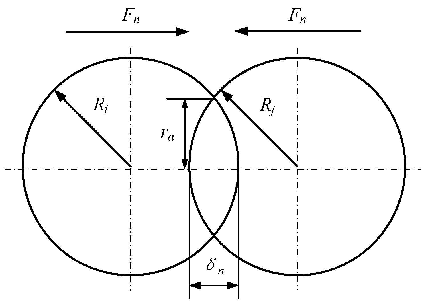
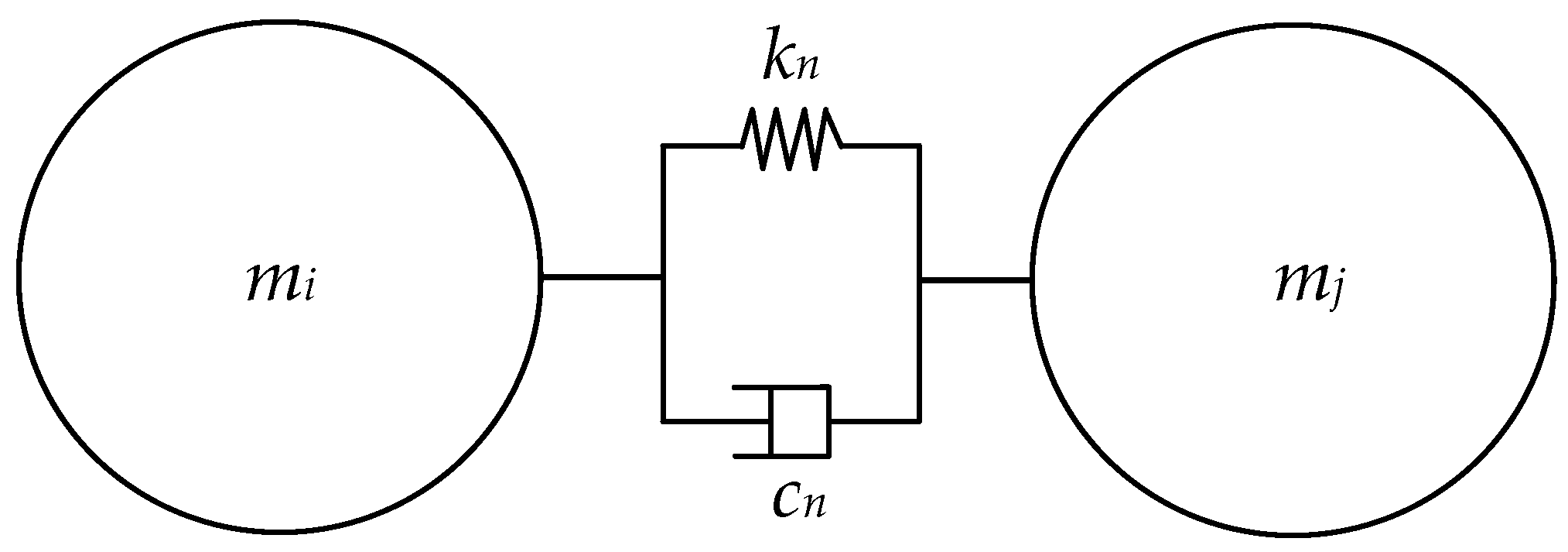
2.1. Analysis of Normal Particle–Particle Collisions
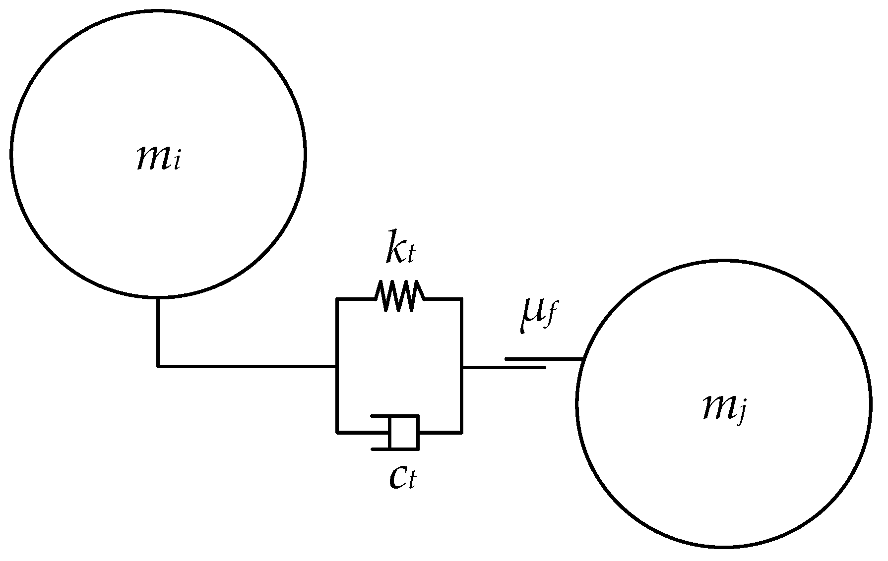
2.2. Analysis of Tangential Particle–Particle Collisions
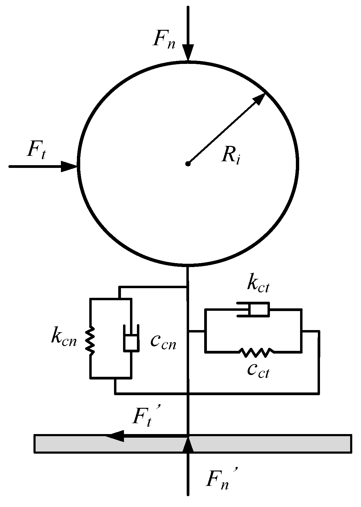
2.3. Analysis of Contact Mechanism between a Particle and the Container Wall
2.3.1. Normal Contact between a Particle and the Container Wall
2.3.2. Tangential Contact between a Particle and the Container Wall
2.4. Analysis of Particle Damping Energy Dissipation Mechanism
3. Design and Simulation of Particle Damper
3.1. Design of the Particle Damper
3.2. Modeling of Particle Damper Using EDEM
3.3. Simulation Parameter Settings
3.4. Analysis of the Influence of Particle Damper Materials and Structural Parameters
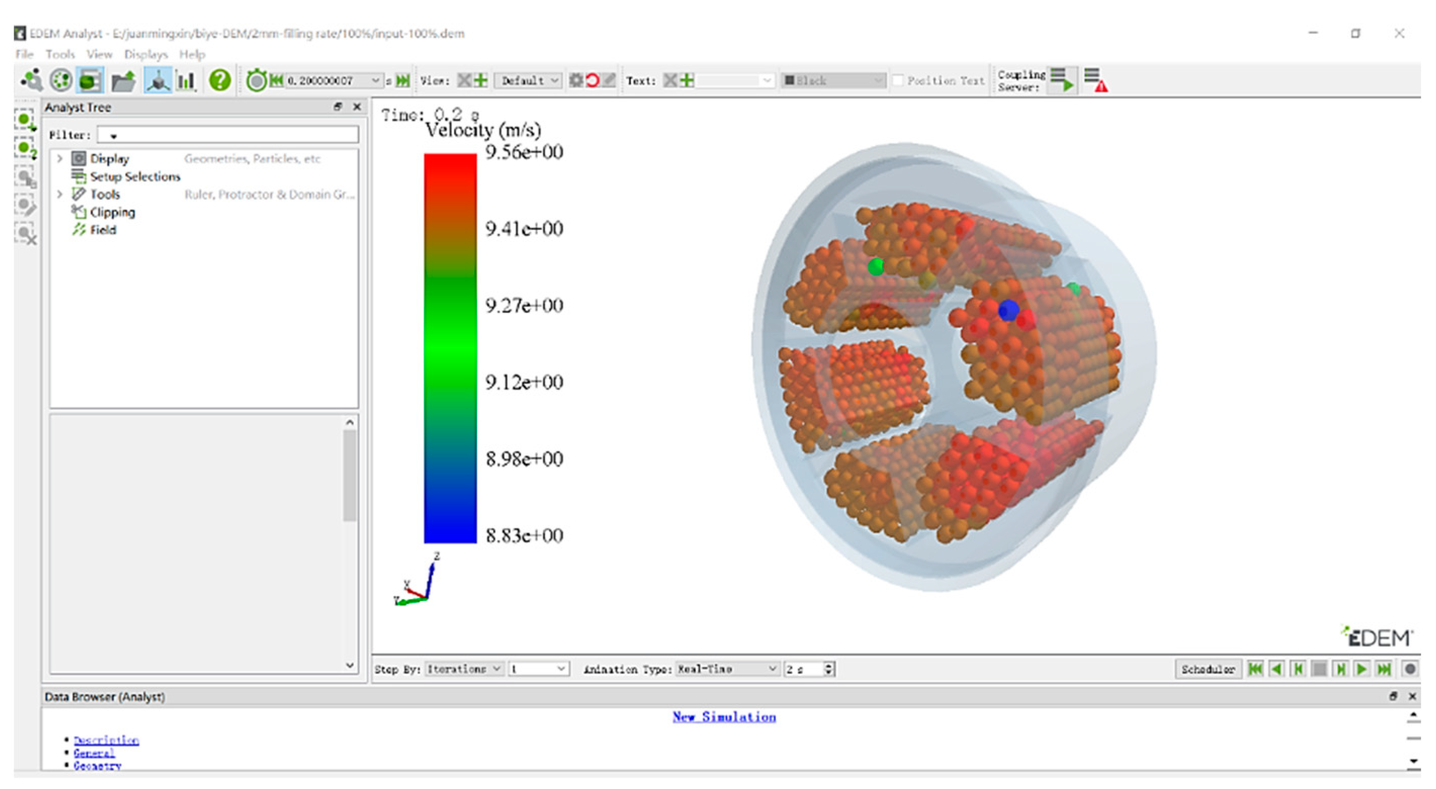
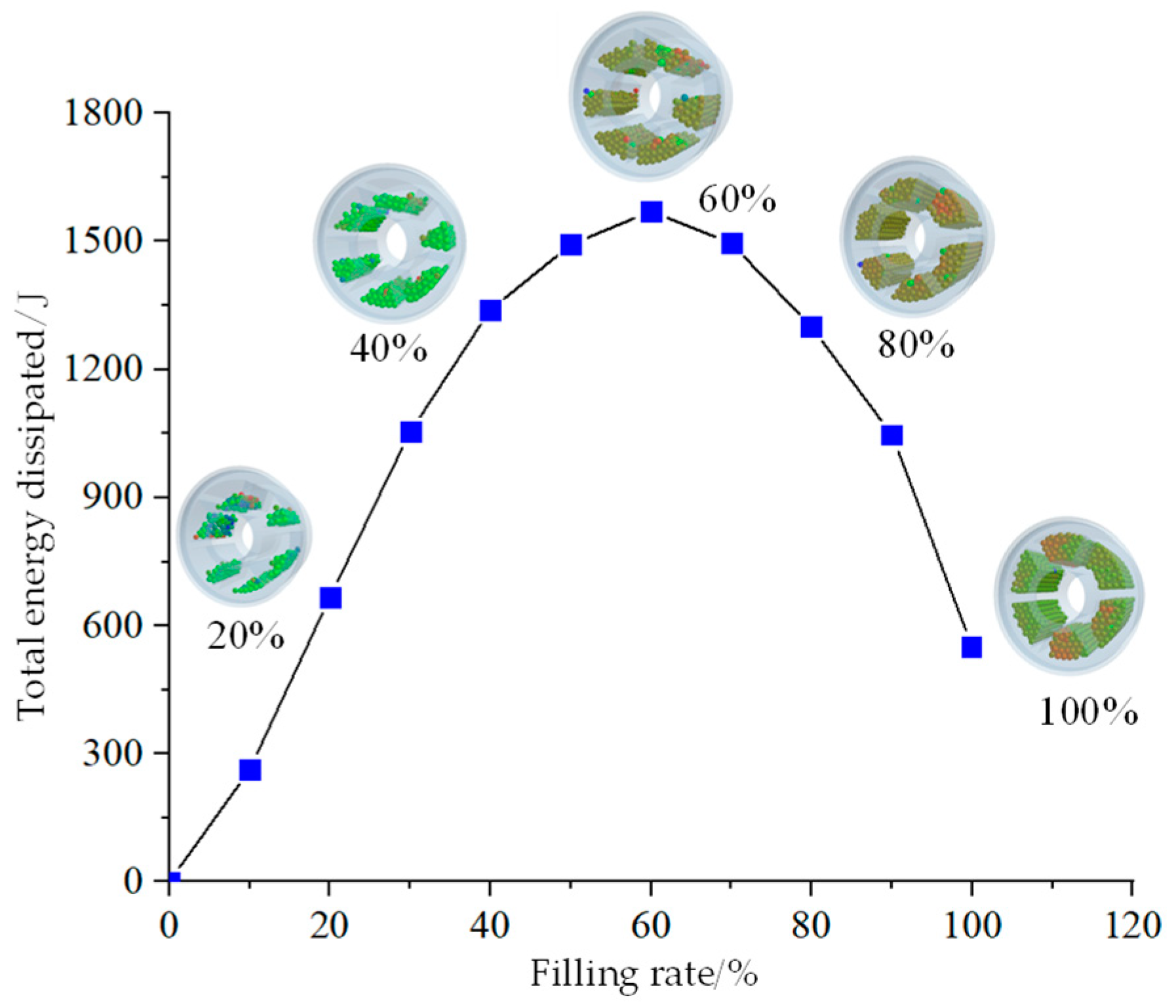
3.4.1. Particle Filling Rate
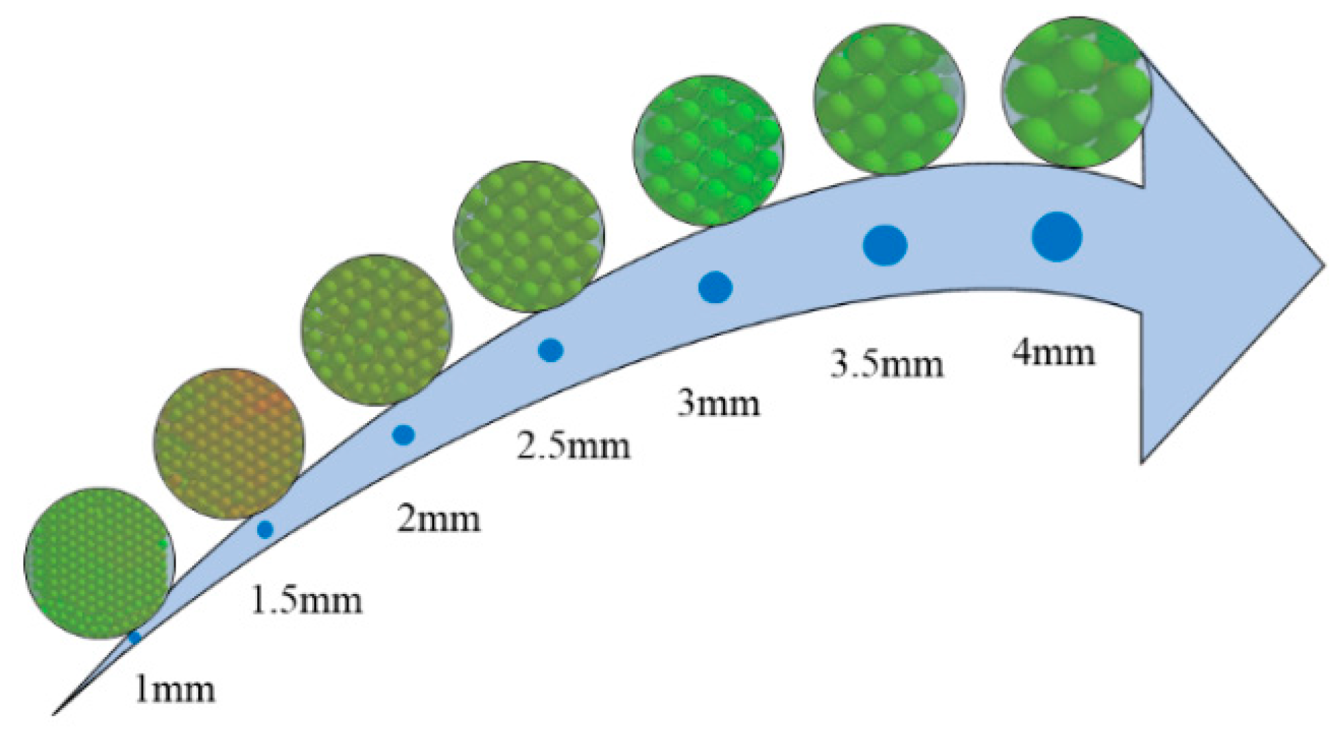
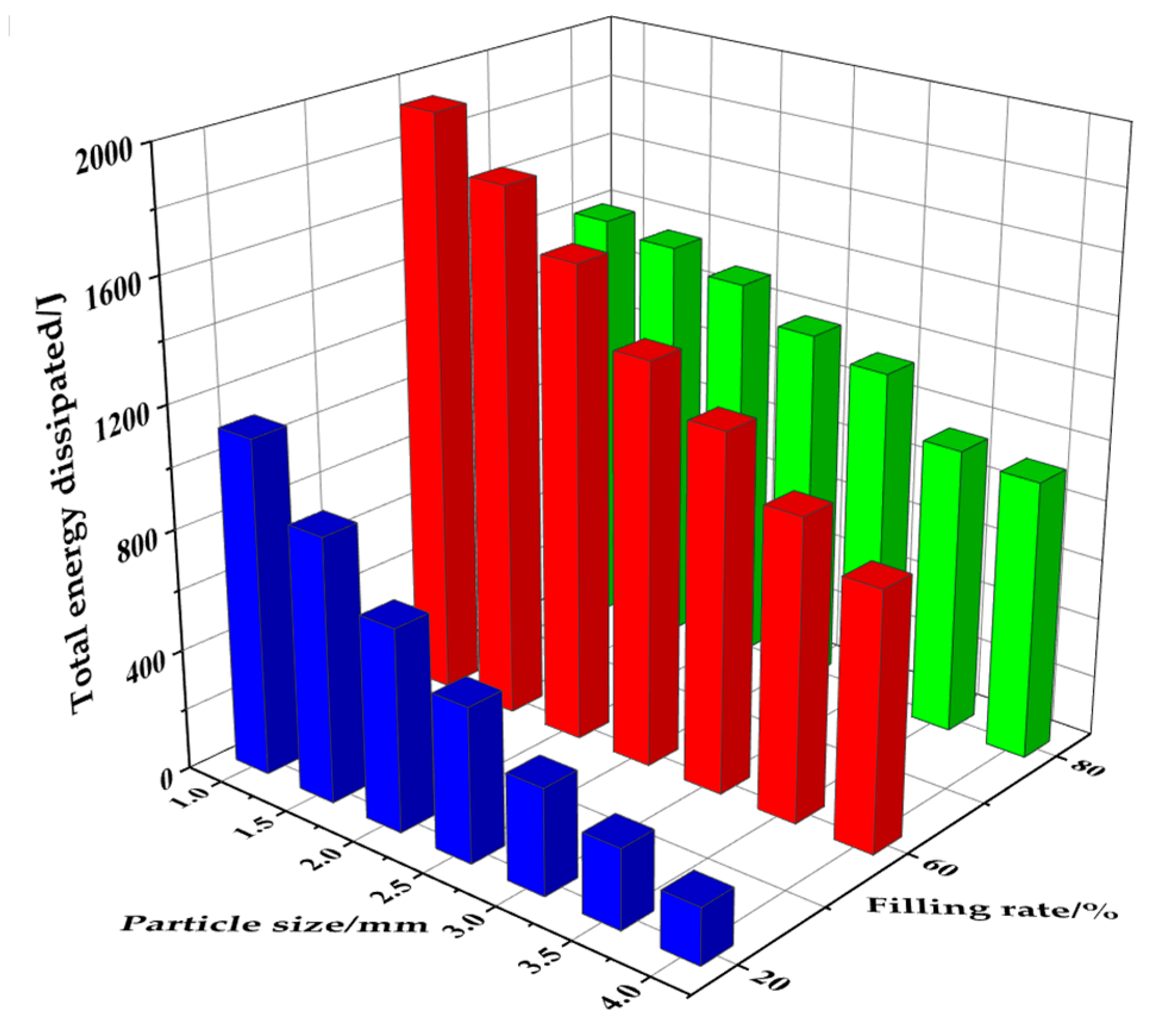
3.4.2. Particle Size
3.4.3. Particle Density
3.4.4. Particle Recovery Coefficient
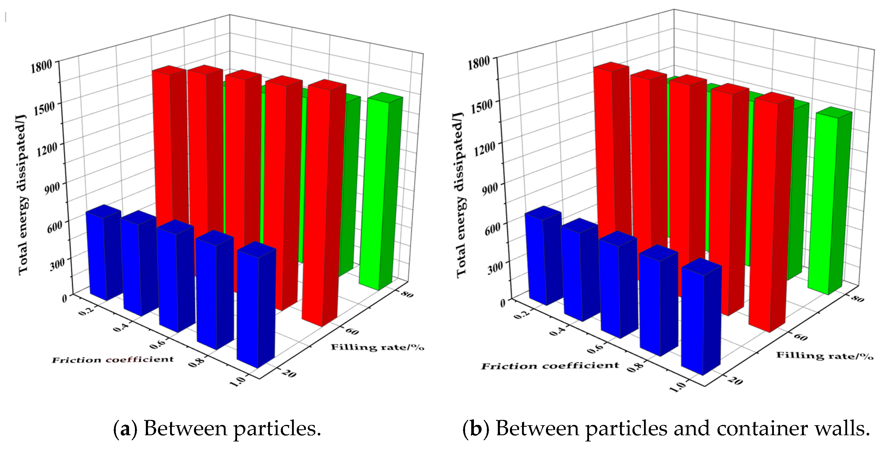
3.4.5. Contact Body Friction
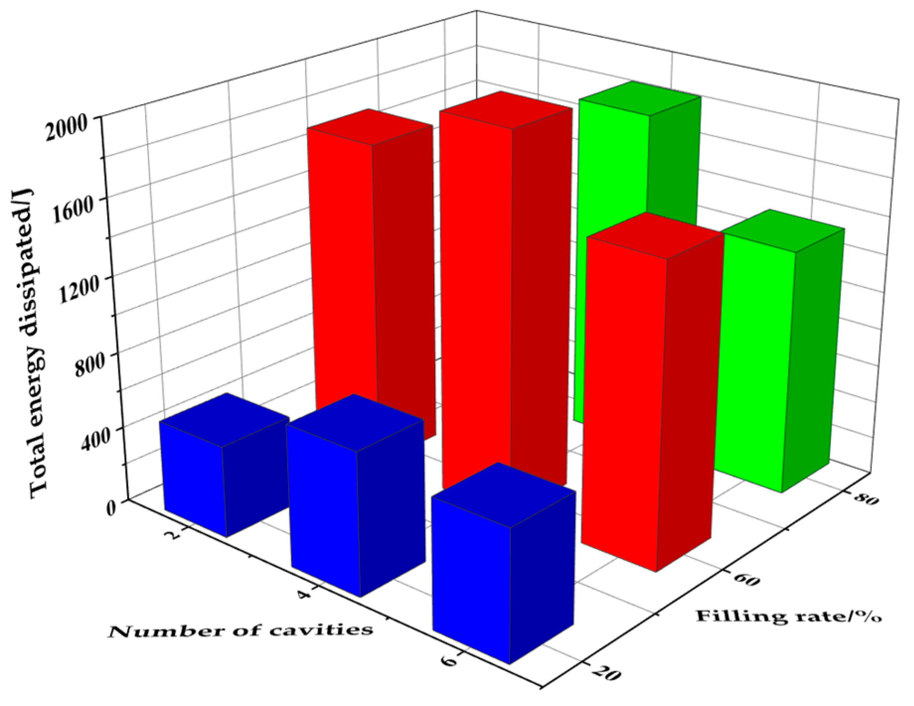
3.4.6. Damper Structure
3.5. Analysis of the Effect of External Excitation Parameters of a Particle Damper
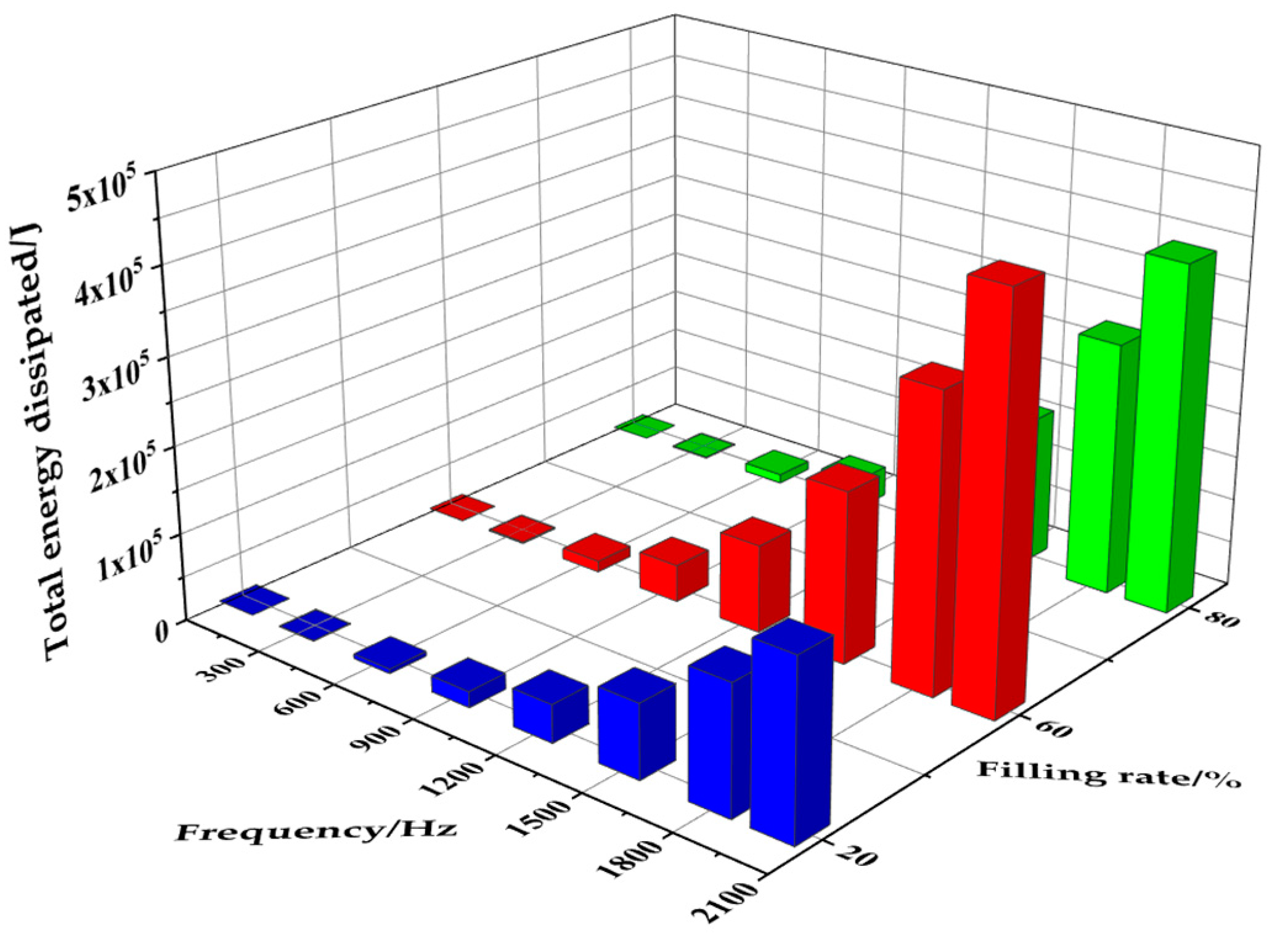
3.5.1. Excitation Frequency
3.5.2. Amplitude Displacement
4. Experimental Verification of the Damping Performance of the Pipeline System
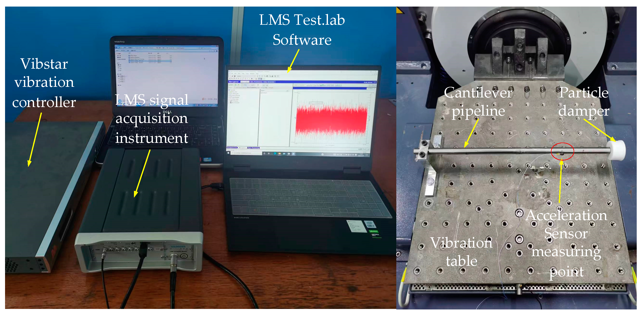
4.1. Test System Set-Up
4.2. Damping Performance Test of Particle Damper under Basic Harmonic Excitation
4.2.1. Influence of Different Materials of Four-Cavity Dampers on the Vibration Damping Performance of Pipeline
4.2.2. Influence of Different Materials of Six-Cavity Dampers on the Vibration Damping Performance of Pipeline
5. Conclusions
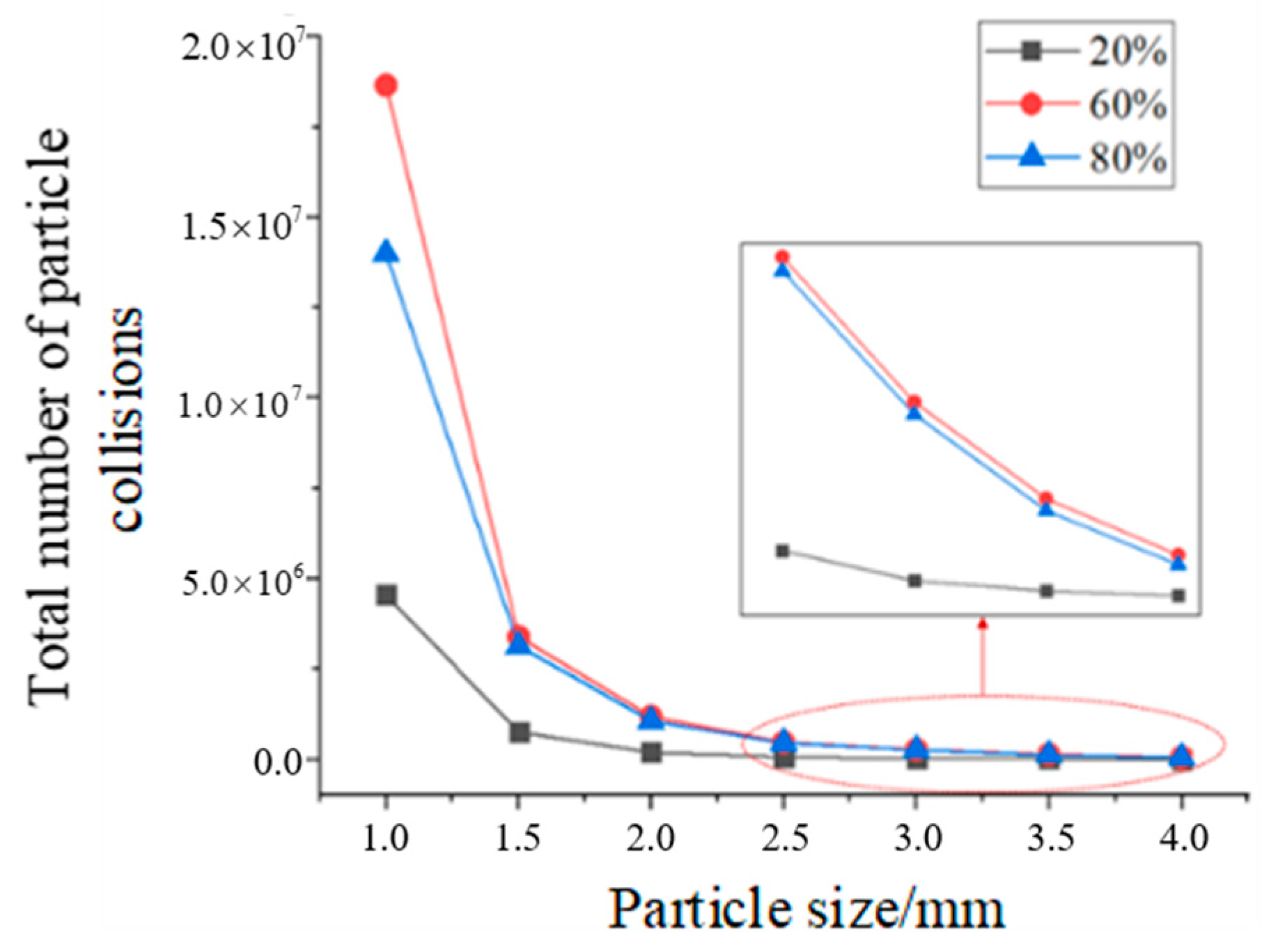
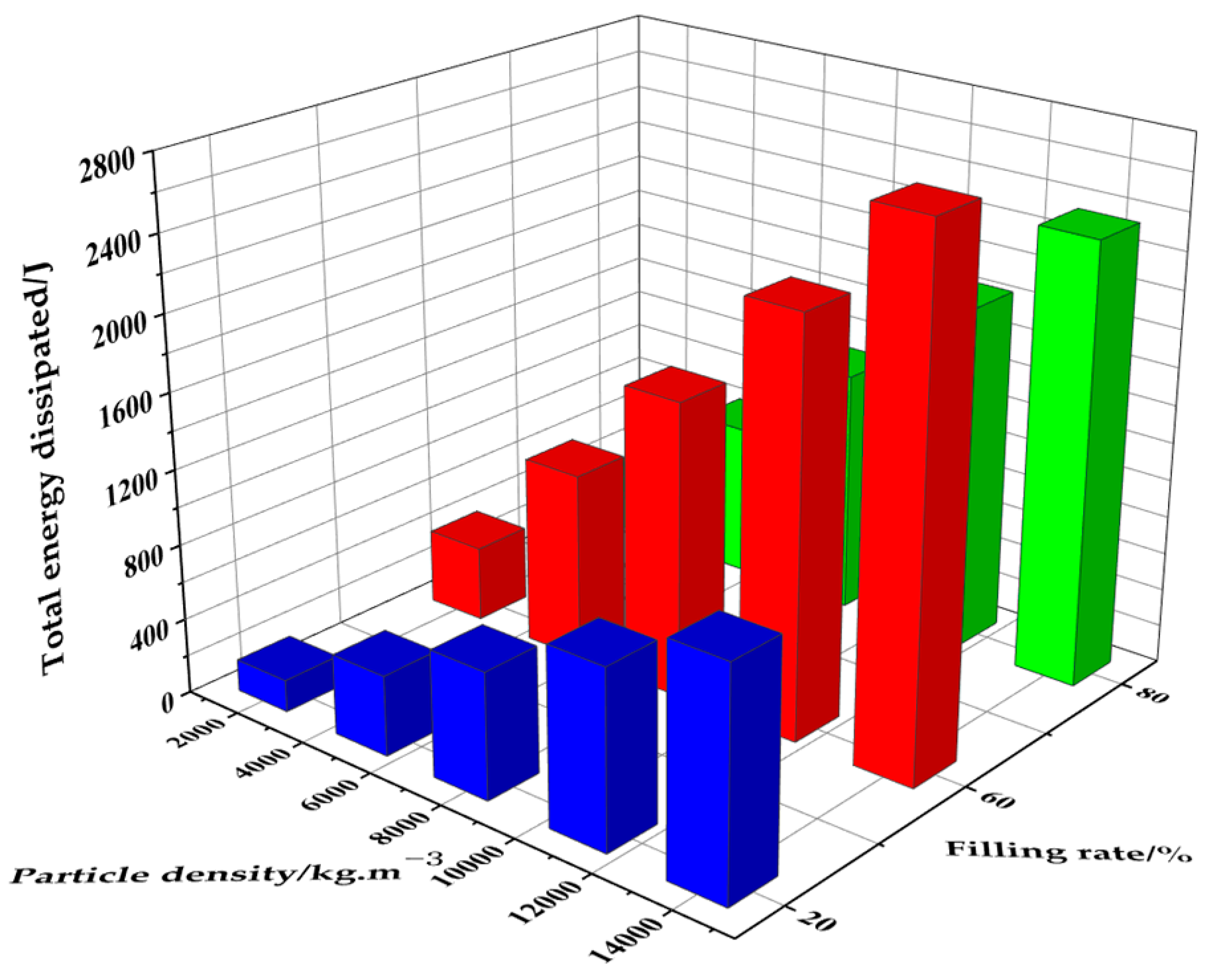
- The total energy dissipated in the particle system shows a trend of increasing and then decreasing with an increasing filling rate. The highest total energy dissipated by the particle system was achieved when the filling rate was 60%. When the damper space is a constant value, the number of particles and energy dissipated in the particle system decreases with increasing particle size. The total energy dissipated by the particle system increases with increasing particle density.
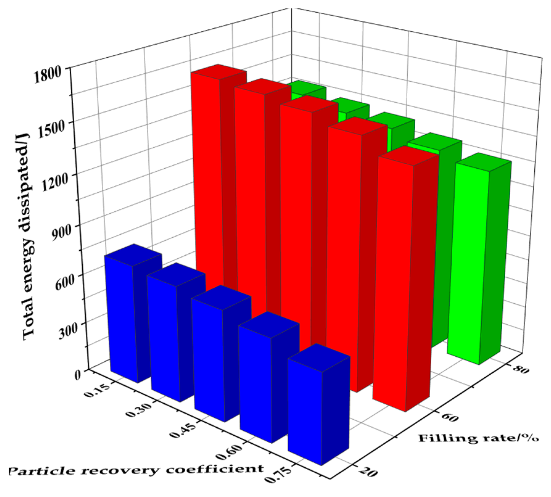
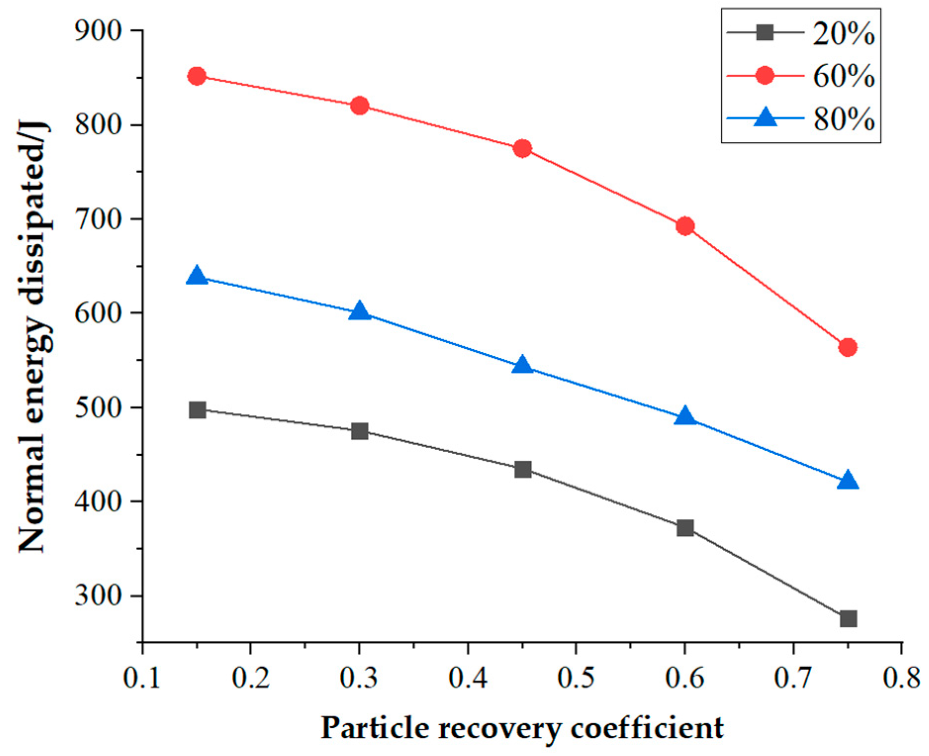
- The total energy dissipated by the particle system increases with increasing particle density, increasing particle–particle and particle–container wall friction coefficients, and decreasing recovery coefficients. The total energy dissipated in the particle system shows a tendency to increase and then decrease with increasing numbers of damper cavities, and the highest total energy dissipated in the particle system was achieved with a four-cavity structure.
- The total energy dissipated by the particle system increases with increasing excitation frequency, amplitude displacement, and number of the damper structure. The frequency domain amplitude of the aluminum alloy damper pipeline decreased by 9.97% and 19.61% for the four-cavity and six-cavity damper configurations, respectively, compared with that of the ABS. This indicates that the damping effect of aluminum alloy particle damper cavities is better than that of ABS dampers.
- For both ABS and aluminum alloy damper structures, the frequency domain amplitudes of the four-cavity damper were smaller than that of the six-cavity ones. This indicates that four-cavity particle dampers have a better damping effect on pipeline systems. Under basic harmonic excitation, the damping effects of the two materials and two-cavity structures have the same pattern when attached to the pipeline.
Author Contributions
Funding
Institutional Review Board Statement
Informed Consent Statement
Data Availability Statement
Conflicts of Interest
References
- Gao, P.; Yu, T.; Zhang, Y.; Wang, J.; Zhai, J. Vibration analysis and control technologies of hydraulic pipeline system in aircraft: A review. Chin. J. Aeronaut. 2021, 34, 83–114. [Google Scholar] [CrossRef]
- Paidoussis, M.P. Fluid-Structure Interactions: Slender Structures and Axial Flow; Academic Press: Cambridge, MA, USA, 1998. [Google Scholar]
- Paidoussis, M.P.; Li, G.X. Pipes conveying fluid: A model dynamical problem. J. Fluids Struct. 1993, 7, 137–204. [Google Scholar] [CrossRef]
- Pan Da, L.N.; Kar, R.C. Nonlinear dynamics of a pipe conveying pulsating fluid with parametric and internal resonances. Nonlinear Dyn. 2007, 49, 9–30. [Google Scholar] [CrossRef]
- Tan, X.; Ding, H.; Chen, L.Q. Nonlinear frequencies and forced responses of pipes conveying fluid via a coupled Timoshenko model. J. Sound Vib. 2019, 455, 241–255. [Google Scholar] [CrossRef]
- Tijsseling, A.S. Fluid-structure interaction in liquid-filled pipe systems: A review. J. Fluids Struct. 1996, 10, 109–146. [Google Scholar] [CrossRef]
- Hu, C.K.; Phillips, J.W. Pulse propagation in fluid-filled elastic curved tubes. J. Press. Contain. Technol. Trans. ASME 1981, 103, 43–49. [Google Scholar] [CrossRef]
- Firouz-Abadi, R.D.; Noorian, M.A.; Haddadpour, H. A fluid–structure interaction model for stability analysis of shells conveying fluid. J. Fluids Struct. 2010, 26, 747–763. [Google Scholar] [CrossRef]
- Ruoff, J.; Hodapp, M.; Kück, H. Finite element modelling of coriolis mass flowmeters with arbitrary pipe geometry and unsteady flow conditions. Flow Meas. Instrum. 2014, 37, 119–126. [Google Scholar] [CrossRef]
- Wiggert, D.C.; Hatfield, F.J.; Stuckenbruck, S. Analysis of liquid and structural transients in piping by the method of characteristics. J. Fluids Eng. 1987, 109, 161–165. [Google Scholar] [CrossRef]
- Yu, D.; Païdoussis, M.P.; Shen, H.; Wang, L. Dynamic stability of periodic pipes conveying fluid. J. Appl. Mech. 2014, 81, 011008. [Google Scholar] [CrossRef]
- Wang, J.; Chen, G.; Zheng, Q.H. Effect of clamp on aircraft hydraulic pipeline dynamic stress. Aeronaut. Comput. Tech. 2014, 44, 64–67. [Google Scholar]
- Zi, B.; Jiang, F.; Wu, Y.; Bai, H.; Tang, Y.; Lu, C. Analysis and experimental research on vibration reduction in ship high-temperature pipeline based on long coated damping structure. J. Mar. Sci. Eng. 2021, 9, 838. [Google Scholar] [CrossRef]
- Jiang, J.; Zhang, P.; Patil, D.; Li, H.N.; Song, G. Experimental studies on the effectiveness and robustness of a pounding tuned mass damper for vibration suppression of a submerged cylindrical pipe. Struct. Control. Health Monit. 2017, 24, e2027. [Google Scholar] [CrossRef]
- Lu, Z.; Lu, X.L.; Masri, S.F. Studies of the performance of particle dampers under dynamic loads. J. Sound Vib. 2010, 329, 5415–5433. [Google Scholar] [CrossRef]
- Shah, B.M.; Pillet, D.; Bai, X.M.; Keer, L.M.; Wang, Q.J.; Snurr, R.Q. Construction and characterization of a particle-based thrust damping system. J. Sound Vib. 2009, 326, 489–502. [Google Scholar] [CrossRef]
- Cui, Z.; Wu, J.H.; Chen, H.; Li, D. A quantitative analysis of the energy dissipation mechanism of the non-obstructive particle damping technology. J. Sound Vib. 2011, 330, 2449–2456. [Google Scholar] [CrossRef]
- Masri, S.F. General motion of impact dampers. J. Acoust. Soc. Am. 1970, 47, 229–237. [Google Scholar] [CrossRef]
- Xu, Z.; Wang, M.Y.; Chen, T. Particle damping for passive vibration suppression: Numerical modelling and experimental investigation. J. Sound Vib. 2005, 279, 1097–1120. [Google Scholar] [CrossRef]
- Jin, G.; Zhao, Z.; Liu, B.; Cun, W.; Zhao, Z.; Hou, M.; Chen, G. Design of a particle damper and experimental study on vibration damping of the pipeline. Adv. Mech. Eng. 2021, 13, 1–14. [Google Scholar] [CrossRef]
- Meyer, N.; Seifried, R. Numerical and experimental investigations in the damping behavior of particle dampers attached to a vibrating structure. Comput. Struct. 2020, 238, 106281. [Google Scholar] [CrossRef]
- Jin, J.; Yang, W.; Koh, H.I.; Park, J. Development of tuned particle impact damper for reduction of transient railway vibrations. Appl. Acoust. 2020, 169, 107487. [Google Scholar] [CrossRef]
- Yang, M.Y. Development of Master Design Curves for Particle Impact Dampers; The Pennsylvania State University: State College, PA, USA, 2003. [Google Scholar]
- Romdhane, M.B.; Bouhaddi, N.; Trigui, M.; Foltête, E.; Haddar, M. The loss factor experimental characterisation of the non-obstructive particles damping approach. Mech. Syst. Signal Process. 2013, 38, 585–600. [Google Scholar] [CrossRef]
- Wang, J.; Juan, M.; Yang, S.; Zhang, D.; Zhang, Z.; Jin, J.; Yu, T. Experimental investigation of the vibration reduction of the pipeline system with a particle impact damper under harmonic excitation. Appl. Sci. 2023, 13, 618. [Google Scholar] [CrossRef]
- Guo, H.; Ichikawa, K.; Sakai, H.; Zhang, H.; Zhang, X.; Tsuruta, K.; Makihara, K.; Takezawa, A. Numerical and experimental analysis of additively manufactured particle dampers at low frequencies. Powder Technol. 2022, 396, 696–709. [Google Scholar] [CrossRef]
- Żurawski, M.; Zalewski, R. Damping of beam vibrations using tuned particles impact damper. Appl. Sci. 2020, 10, 6334. [Google Scholar] [CrossRef]
- Xu, Z.L. Elasticity; Higher Education Press: Beijing, China, 1990. [Google Scholar]


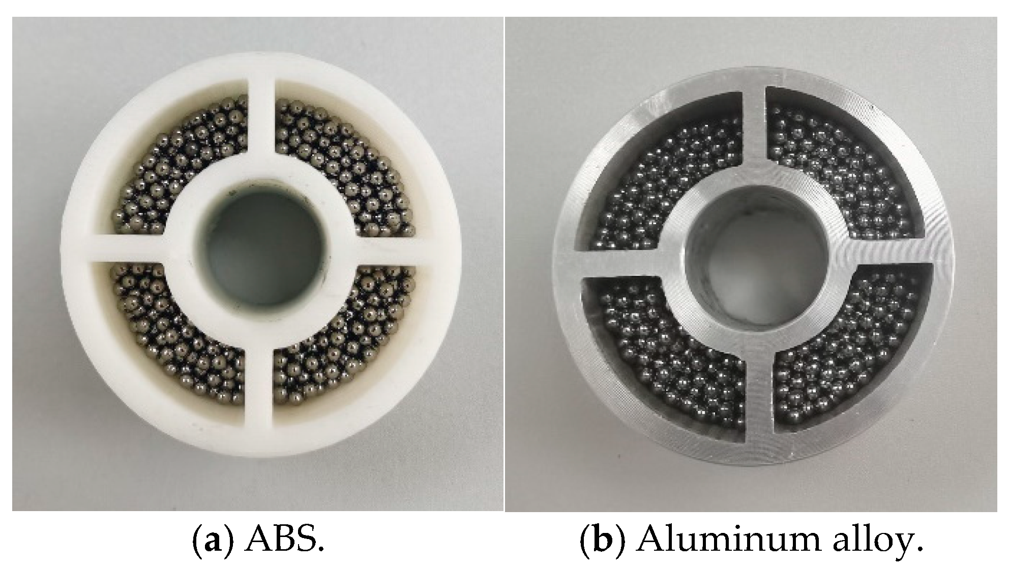
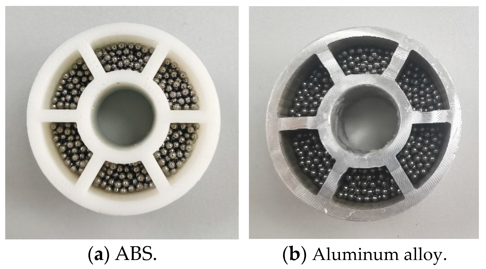
| Two Cavities | Four Cavities | Six Cavities | |
|---|---|---|---|
| Design drawing | 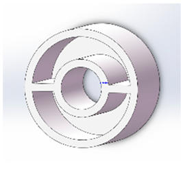 |  | 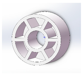 |
| ABS | 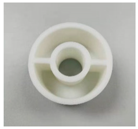 | 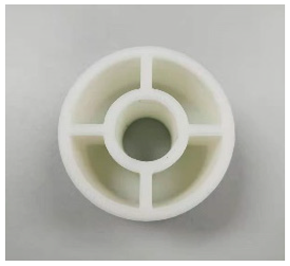 | 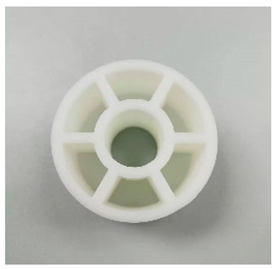 |
| Aluminum alloy | 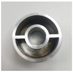 | 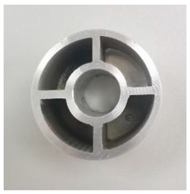 | 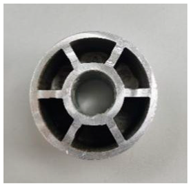 |
| Inner Diameter | Outer Diameter | Container Height | Wall Plate Thickness | Cover Plate Thickness |
|---|---|---|---|---|
| 16.5 mm | 46 mm | 28 mm | 3 mm | 1 mm |
| Material | Density (ρ) (kg·m−3) | Elasticity Modulus (E) (GPa) | Poisson Ratio (μ) |
|---|---|---|---|
| Steel | 7850 | 200 | 0.3 |
| Aluminum alloy | 2800 | 68.9 | 0.33 |
| Contact | Coefficient of Recovery | Coefficient of Static Friction | Coefficient of Rolling Friction |
|---|---|---|---|
| Steel–Steel | 0.45 | 0.15 | 0.15 |
| Steel–Aluminum alloy | 0.45 | 0.17 | 0.001 |
| Filling Rate (%) | Number of Particles | Mass Ratio (%) |
|---|---|---|
| 10 | 203 | 6.68 |
| 20 | 406 | 13.35 |
| 30 | 609 | 20.03 |
| 40 | 812 | 26.73 |
| 50 | 1015 | 33.38 |
| 60 | 1218 | 40.05 |
| 70 | 1421 | 46.73 |
| 80 | 1624 | 53.40 |
| 90 | 1827 | 60.08 |
| 100 | 2030 | 66.75 |
Disclaimer/Publisher’s Note: The statements, opinions and data contained in all publications are solely those of the individual author(s) and contributor(s) and not of MDPI and/or the editor(s). MDPI and/or the editor(s) disclaim responsibility for any injury to people or property resulting from any ideas, methods, instructions or products referred to in the content. |
© 2023 by the authors. Licensee MDPI, Basel, Switzerland. This article is an open access article distributed under the terms and conditions of the Creative Commons Attribution (CC BY) license (https://creativecommons.org/licenses/by/4.0/).
Share and Cite
Ma, R.; Shi, F.; Juan, M.; Wang, J.; Jin, J.; Yu, T. Numerical and Experimental Investigations of Particle Dampers Attached to a Pipeline System. Appl. Sci. 2023, 13, 13217. https://doi.org/10.3390/app132413217
Ma R, Shi F, Juan M, Wang J, Jin J, Yu T. Numerical and Experimental Investigations of Particle Dampers Attached to a Pipeline System. Applied Sciences. 2023; 13(24):13217. https://doi.org/10.3390/app132413217
Chicago/Turabian StyleMa, Rui, Fuqiang Shi, Mingxin Juan, Jiao Wang, Jie Jin, and Tao Yu. 2023. "Numerical and Experimental Investigations of Particle Dampers Attached to a Pipeline System" Applied Sciences 13, no. 24: 13217. https://doi.org/10.3390/app132413217
APA StyleMa, R., Shi, F., Juan, M., Wang, J., Jin, J., & Yu, T. (2023). Numerical and Experimental Investigations of Particle Dampers Attached to a Pipeline System. Applied Sciences, 13(24), 13217. https://doi.org/10.3390/app132413217