Abstract
The use of composite precast or steel bars as reinforcements for timber beams is an important technique that can improve effectiveness or allow cross sections to be reduced. This paper presents experimental, theoretical, and numerical studies of full-size timber beams measuring 82 × 162 × 3650 mm3 using prestressed steel bars and 10 mm diameter basalt and glass bars with a prestress of 10 MPa. In addition, parametric studies were carried out using FEM numerical simulations. In the experimental tests, an increase in load-bearing capacity and stiffness of up to 58% and 10.7% for steel bars, 32% and 10.1% for basalt bars, and 27% and 7.8% for glass bars, respectively, was obtained compared to unreinforced beams. The different levels of improvement in reinforcement efficiency was also related to the different elastic modulus of the reinforcement itself. Unreinforced beams showed a linear elastic range. In contrast, on beams reinforced with steel bars, the curve had a slightly steeper line than the control beam, and the slope of the curve then decreased when a certain load was reached. All beams failed when the lower wood fibers reached maximum tensile strain. The allowable compressive strain then decreased by 36.6% for basalt bars, 32.9% for glass bars, and 30.4% for steel bars. The use of prestressing further exploited the strength of the reinforcement beyond the yield point. All unreinforced beams primarily failed in the tension zone due to fracture of the timber fibers. Prestressed and reinforced beams were already failing due to bending and shear. The experimental and numerical analysis was also compared, and the results showed a good agreement and a maximum difference of approximately 5.7%.
Keywords:
wooden beams; bending; strength; load-bearing capacity; deformability; bars; FRP; steel; FEM 1. Introduction
Wood is a very interesting material used in construction. The economic benefits of wood can include availability, low cost, and ease of production. As a result, it is now possible to build wooden structures of any size and shape. Compared to other building materials, wood is a material of organic origin and is anisotropic; therefore, its strength and mechanical properties vary significantly. In order to achieve and meet the demand for timber construction, experimental studies are required to be carried out [1,2,3,4].
Currently, wood is becoming more and more common in innovative civil construction related to multistory buildings, halls, sports infrastructure, schools, houses, and bridges usually for pedestrian traffic. It is a widely used material because of its lightness and strength. Wooden materials provide good resistance to compressive and tensile loads, aesthetic appearance, good fire resistance, profitability, ease of manipulation and use as prefabricated elements, and significant thermal and acoustic insulation [5,6,7,8,9,10,11].
Compared to steel, concrete, and other building materials, wood is an environmentally friendly material due to its durability. It should be noted that wood is an organic material that can be easily destroyed due to aging or environmental processes (e.g., moisture and temperature) as well as biological attacks (e.g., fungi and insects). This degradation of wood is a very important factor to consider because wood is used as structural elements of buildings. For this reason, attempts to repair or strengthen wood are necessary so that wooden structures can be characterized by significant durability and safety [5].
It should be noted that structural timber products, such as glued laminated timber (glulam), cross-laminated timber (CLT), laminated veneer lumber (LVL), I-beams, and solid timber joined with wedge joints, are becoming more common as substitutes for conventional building materials, such as concrete or steel. Recently, glulam, CLT, and I-beams have become very popular. All these types of timber elements are worth reinforcing with fiber composites or steel, except for LVL due to the already high strength. LVL is most often used as a structural element to obtain high strength, e.g., as lintels over large-size glazing or garages, foundations, and wall supports. It is more common for designers to use solid timber with spliced joints on the floors. If they need to achieve very high strength or have a smaller cross-sectional height in order to use slender construction materials, I-beams are more often used because of their lower cost while still achieving high strength. Designers are now increasingly using different sizes of I-beams, but they usually use I-beams instead of solid wood for wedge joints at higher heights, i.e., 60 × 300 mm2 and higher. This is a very good solution using I-beams. Depending on the static patterns and loads, designers also use smaller cross sections of I-beams, e.g., to use less space intended for the ceiling while achieving high strength, thereby saving the cross section of the structural element and space. This is very important because the price of structural lumber is increasing. Considering resource-efficient, eco-friendly construction, timber frame construction is highly cost-effective due to the return on heating costs. In contrast, considering the cost of LVL and fiber composites (even basalt or glass rods alone are very cheap reinforcing materials on the market compared to other reinforcing elements, even for steel alone), it is still very expensive to reinforcement and LVL to obtain strong load- in order to obtain an even greater increase in the load-bearing capacity or stiffness of a prefabricated LVL element made of glued veneer with a smaller cross-section or smaller span. In the scientific literature, we can find many studies on the reinforcement of full-length LVL members with composite or steel bars as well as with mats, tapes, etc. [12]. LVL already has high strength and very high mechanical properties, which is very beneficial for many design solutions. A very good and innovative solution is the reinforcement of I-beams, where the chords are only made of glued veneers. This is very important because these elements are very cheap and very light, making them applicable as modular, frame, or prefabricated elements. Glulam is created by arranging and joining layers of wood in the same direction as the wood grain. CLT is created by rotating the direction of the fibers relative to the adjacent layers by approximately 90 degrees. It is made of engineered wood and widely used in construction in the USA, Canada, Europe, and Asia [12,13,14]. It should be noted that the cost of glulam and CLT is higher than steel or concrete, but they are still low-density materials that allow significant savings in transport and foundations. In addition, timber structures are usually transported half finished, which helps maintain cleanliness and saves time during assembly [15].
The number of timber buildings has continued to increase due to the lightweight and low carbon footprint of timber structures. Therefore, the use of structural timber products is expected to continue to increase accordingly. Consequently, issues concerning the strengthening of structural timber elements (e.g., repairing/upgrading existing timber buildings and strengthening prefabricated timber elements for multistorey structures) should be considered [16].
An important way to solve the above problems is to strengthen wooden elements using composite materials made of fiber-reinforced polymers (FRP). Numerous experimental, theoretical, and numerical studies can be found in the literature on the use of carbon, aramid, glass, basalt, hybrid, and steel in the form of bundles, strips, mats, cords, shapes, and rods to reinforce structural timber members [17,18,19,20,21,22,23,24,25,26,27,28,29]. Based on experimental studies, Nadir et al. [29] found that reinforcing composite glued beams (made of rubberwood) with a two-layer glass-fiber-reinforced polymer (GFRP) and a two-layer carbon fiber-reinforced polymer (CFRP) could increase flexural strength values by 40% and 51%, respectively. Bal [10] produced a LVL (poplar)–GFRP composite, and glass fabrics and veneers were laid layer by layer. The MOE and modulus of rupture (MOR) of the LVL–GFRP composite were obtained from a three-point bending test. Based on experimental studies, the MOE and MOR of LVL– GFRP were 14% and 40% higher than poplar LVL, respectively. Bal et al. [30] also investigated the water absorption and bending behavior of polar plywood, where glass fabrics were placed between the plywood layers. Based on experimental tests, it was found that the addition of glass fabrics reduced the water absorption (by 15–23%) of LVL and significantly increased the MOE (by 70–118%) and MOR (by 35–50%) of plywood towards the perpendicular direction. Also, it should be noted that, in addition to studies of timber beams reinforced with one type of FRP, there are studies of timber beams reinforced with synthetic hybrid FRP consisting of two or more types of synthetic fibers in one type of matrix. In their experimental research, Zhang et al. [31] used hybrid carbon, aramid, and glass fibers to reinforce wooden beams that had circular cross sections. The results showed that hybrid FRP with carbon, aramid, and glass fibers in a 2:1:1 ratio could achieve a stiffness increase of 69–115% in wooden beams. In [32], comprehensive research was conducted on the strengthening of timber beams using steel plates. Furthermore, the paper detailed how the application of plastic theory could be used to optimize the design of timber beams, ensuring their structural integrity and strength. Reinforcing timber beams with steel plates improved the behavior while also increasing the overall strength. Maglad et al. [33] investigated the effectiveness of timber plate strengthening of reinforced concrete (RC) beams that contained waste sawdust as a partial replacement for fine aggregate (sand). Initially, a wooden board was used, attached only with a layer of glue. Then, the wooden board was attached with a layer of glue and steel angles (2 and 11 angles). The results showed that despite the workability of the concrete, the ultimate load of the SD beam was lower than that of the control beam, with a slight difference of about 4%. In addition, reinforcement of the concrete beam with a timber slab and two steel angles gave the highest load-bearing capacity of all the beams tested, which was 20% higher than the control specimen. The study results provided useful information for the development of environmentally beneficial sawdust concrete beams equipped with effective strengthening techniques for future applications. Gand et al. [34] studied the effect of reinforcing timber beams with basalt-fiber-reinforced polymer (BFRP) bars and obtained an increase in the allowable load capacity of 16% on average. Borri and Corradi [35] conducted experimental tests on bending of the reinforcement of wooden beams using very-high-strength steel ropes. Tests showed that external reinforcement of steel fibers resulted in a large increase in stiffness and bending strength. Soriano et al. [36] conducted research using steel bars to strengthen glulam beams. In their research, they achieved an increase in stiffness and improved mechanical properties.
Jasieńko and Nowak [37] studied timber beams using steel plates. They obtained results comparable to those of fiber-reinforced polymers (FRP). In another study, Borri et al. [38] strengthened wooden beams using composite materials based on natural fibers, hemp, flax, basalt, and bamboo. Based on the study, the use of natural fiber composites was found to be more effective for timber beams with inferior mechanical properties. In a subsequent study [39], bamboo scribes were added to timber beams [39], with gains in maximum load capacity ranging from 20% to 70% and stiffness from 40% to 160%. In CLT, small cracks can lead to loss of mechanical strength, while the use of cracks filled with other materials in engineered wood products may have the potential for design innovation and improved acoustic and thermal properties [40].
Due to its orthotropic nature, wood is a complex material and has limited analytical capabilities to describe its basic behavior. However, the existence of knots, cracks, or inclination of the grain also has an important impact on the behavior of the wooden structural element, especially when they are located in the tension zone because that is where the most damage can occur. In addition, the properties of wood may differ even within the same species; therefore, many parameters will need to be considered to fully describe the model. However, fibers have no meaning until they are connected to each other to create a durable load-bearing element. Their advantages are related to a highly organized internal structure or a low probability of structural defects. The most common fibers used to construct FRP rods are glass, carbon, aramid, and basalt. Please note that fibers differ in many properties related to production processes or types of particles. Aramid fibers are the lightest, carbon fibers are the most durable, glass fibers are the cheapest, and basalt fibers are the most resistant to high temperatures. Therefore, all fibers are characterized by a typically linear stress–strain relationship. Stresses and strains increase linearly with the applied load until failure. It is linear with different angles of inclination, which differ in elastic moduli (smaller than for steel). Therefore, it is proportional to the load capacity. It is known that the higher the modulus of elasticity, the greater the increase in load capacity. Composite bars have different strength characteristics than steel bars; therefore, in the calculation of both the ultimate limit state and the serviceability limit state, it will be necessary to make different design assumptions regarding safety conditions. Composite bars are linear elastic in nature. However, FRP bars do not have the ability or the possibility, beyond certain stresses, to introduce plastic reinforcement or redistribute internal forces, which distinguishes them from steel. In the same way, there is no increment of plastic deformation of the bars to determine the impending catastrophe. Therefore, deformation may build up until it exceeds a certain value, and brittle failure of the member may then occur. It should be added that it is usually the limiting strain that generates the amount or size of reinforcement. However, it may also happen that it is not the stress or strain limit state criteria that are decisive in the design process but rather factors such as fatigue resistance and resistance to sudden member rupture resulting from creep. In steel-reinforced structures, on the other hand, it is practically always this ultimate limit state that is decisive. Equally, it should be noted that the strength of a composite bar decreases as its diameter increases, and this is unheard of in steel bars.
This paper presents another alternative method of strengthening timber beams using steel and basalt and glass in the form of prestressed bars. This study aims to investigate the effectiveness of the reinforcement, which can then be applied to all types of timber beams. A tension force of 10 MPa was applied to the reinforced bars, corresponding to approximately 2% of the ultimate tensile strength of steel, as the element with the lowest tensile strength. In addition, the load capacity of the beams, stiffness values, and MR as a function of mid-span deflection and failure mechanisms were analyzed experimentally. FEM numerical models were also used to compare the results to the experimental studies.
In this study, the main objective was to show the differences in static work after using different fibers and steel. It should be noted that basalt and glass fibers achieve the highest tensile strength as well as all fibers having a tensile strength higher than steel. Glass fibers have surprisingly good wettability through polymers, so the resin adheres easily to them, while the number of air voids at the interface between the materials is negligible. Therefore, very good adhesion can be obtained between fibers and the polymeric material. Glass fibers are also characterized by their high tensile strength or lack of electrical conductivity as well as low thermal expansion. They also have disadvantages, such as the fact that their tensile strength and modulus of elasticity decrease at elevated temperatures. Glass fibers also tend to creep under long-term loading, their strength decreases over time, and they have less corrosion resistance than other fiber types. However, these disadvantages can be mitigated using hybrid bars through the right selection of component materials. Because of the cheap cost of these bars, they are the most widely used material in construction. Basalt fibers, on the other hand, are a single-component material obtained by melting solidified volcanic lava. These fibers already have better physical and mechanical properties than glass fibers and are also relatively cheap. For this reason, along with glass fibers, they are also the most widely used raw materials for composite bars. It should be noted that the main positive characteristics of these fibers include high fire resistance, high sound insulation, high fatigue strength, and internal vibration damping capability. It should also be noted that these fibers have a fiber operating temperature of 982 °C; a fiber melting point of 1450 °C; high hardness; and high resistance to corrosion, including acid and alkaline corrosion, which is very important when compared to steel. FRP fibers are characterized by their high strength and stiffness and yet low weight and size. In addition, GFRP rods have a lower elastic modulus, while BFRP rods have a higher one. This is because composite fibers have the most important role in determining the elastic modulus of FRP bars. In addition, all FRP bars have a lower modulus of elasticity than steel, which is related to the fact that it has poorer resistance to the effects of creep. In composite materials, fibers have much better resistance to high temperatures than the resin surrounding them. It should be noted that beams reinforced with FRP bars subjected to tension at elevated temperatures often fail through anchorage degradation. The threshold temperature for fiber operation is approximately 880 °C for glass fibers and approximately 1250 °C for basalt fibers. Moreover, the mechanical properties of composite rods deteriorate as the temperature increases, but if it does not exceed the glass transition temperature of the fibers, they return almost completely to their initial values. In prestressed structures, it should be considered that due to the relatively high coefficient of transverse thermal expansion, additional stresses may arise at the bar–wood interface. Moreover, long-term exposure to negative temperatures may cause hardening of the matrix or microcracks as well as reduced adhesion between the matrix and individual composite fibers. Likewise, freeze–thaw cycles combined with the action of salt may also result in the deterioration of the resin properties, visible in the form of swelling of the polymer on the surface of the rod. To prevent the possibility of decreased adhesion between FRP rods and concrete due to the expansion and contraction of the rods under the influence of temperature cycles and degradation resulting from frost, the rod cover and composite building blocks should be selected appropriately to the type of rod and the element’s operating environment. At the same time, to ensure proper functioning of the structure at elevated temperatures, it is necessary to select a cover that protects the rod against the influence of high temperatures as well as to properly know the type of polymer resin material and the type and size of fibers from which the composite rods are made. According to [41], fiber-reinforced polymer composites have very good properties for replacing steel in bridge cables or underground oil extraction and ocean engineering. All these are related to advantages such as low weight, high strength, and the desired resistance to corrosion and fatigue. In this work, two types of carbon fiber and glass hybrid wafers were developed, including random mode hybrid (RH) and core–shell hybrid (CH). Based on the tests, it was found that the maximum percentage increase in tensile and bending strength for the RH board after 360 days was 51.3% and 39.7%, respectively. In [42], rods made of hybrid fiber-reinforced polymer (HFRP) with a glass fiber coating (GFS) and a carbon fiber core (CFC) were used as an alternative solution to steel materials and used in a bridge cable. Based on the research, it was found that the degradation of hybrid bars increased with increasing temperature or bending load levels. It was also recommended that the level of cyclic bending load applied should not exceed 50% to allow for the desired durability of bridge structures.
2. Materials and Methods
2.1. Materials
The experimental test comprised a bending test of 20 full-size fir and Scandinavian pine timber beams (beam dimensions 82 × 162 × 3650 mm3) under static loading. Previously, the lumber was visually graded for strength according to PN-D-94021:2013-10 [43]. All the structural and geometric features of timber were analyzed, with the wood quality classified as the KW class. Thus, the formed reinforced beams were divided into three types according to the type of reinforcement, namely, 10 mm diameter steel bars (type ‘D’), 10 mm diameter basalt bars (type ‘B’), and 10 mm diameter glass bars (type ‘C’), corresponding to 1.8% reinforcement. Reinforcement of the beams was carried out in the tension zone using composite bars and steel bars.
The glulam beams were made of pine and Scandinavian fir. The properties of the timber materials, on the other hand, were obtained in accordance with the standard material test methods for timber samples from EN 408+A1:2012 [44].
2.1.1. Wood
Bending strength, tensile strength, compressive strength, shear strength, and modulus of elasticity were determined in accordance with EN 408+A1:2012 [44], PN-77/D-04229 [45], PN-79/D-04102 [46], PN-79/D-04105 [47], PN-81/D-04107 [48], and PN-81/D-04108 [49]. The test pieces consisted of 10 test specimens each along and across the fibers. The properties of the tested samples are presented in Table 1. The deformation in the central region of the specimens was determined using a strain gauge. All tensile specimens fractured in the central area.

Table 1.
The mechanical properties of the wood along and across the fibers were investigated.
The average flexural strength and average compressive strength along the fibers were 82.5 and 55.6 MPa and the standard deviations were 8.2 and 7.9 MPa, respectively. The average humidity was 10.2% (standard deviation, 0.15%). The reinforcement of the timber beams was carried out by placing bars on the bottom side of the beam into premilled grooves. All tested beams, including unstrengthened control beams, were tested in five repetitions in a four-point loading scheme using a 100 kN universal testing machine in accordance with the EN 408+A1:2012 standard [44]. During the tests, the machine recorded load, deformation, and deflection. Figure 1 shows a photo of the test system during the experimental bending test.
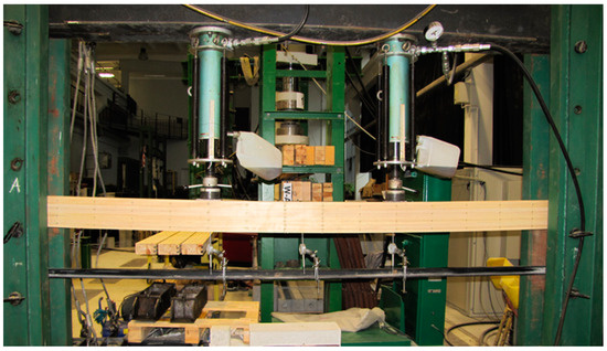
Figure 1.
A test scheme of glued laminated timber beams.
2.1.2. Steel, BFRP, and GFRP Bars
Twenty steel bars with a diameter of 10 mm were used during the tensile tests. The tests used longitudinally ribbed steel bars with an average diameter of 10 mm. A testing machine was used to analyze the axial tension parameters of steel bars. The steel was marked in accordance with the PN-H-93220:2018-02 [50] standard for reinforcing bars (B500SP EPSTAL). The experimental test results are presented in Table 2. The yield strength and elastic modulus of the steel reinforcing bars were 521–595 MPa and 203.2–205.9 GPa, respectively. The yield strain ranged from 0.0021 to 0.0023. In order to obtain the mechanical properties of BFRP and GFRP bars, tensile tests of 10 identical specimens each were carried out in accordance with GOST 31938:2012 [51]. Table 1 shows the mechanical properties of GFRP, BFRP, and steel bars. Available POLPREK (Warszawa, Poland), Trokotex Polymer Group Sp. z.o.o. (Toruń, Poland), and EPSTAL, CENTROSTAL S.A. (Warszawa, Poland) bars were used for longitudinal reinforcement.
Table 2.
The mechanical properties of the bars.
2.1.3. Epoxy-Resin-Based Adhesive
Taking into account the favorable mechanical properties, it should be noted that epoxy-resin-based adhesives ideally fill holes and are effective for bonding. Liquid epoxy resin can be used to bond steel, BFRP, CFRP, and wood pore filling to increase the adhesion of reinforcing materials to wood. Therefore, liquid epoxy resin and S&P Resin 55 HP hardener were used in this study [52]. This allowed better filling of the wood pores and increased adhesion. S&P Resin 55 HP is a two-component, solvent-free epoxy-resin-based adhesive with an amine hardener. A weight ratio of 4.2:1.8 (A:B) was used to combine the epoxy resin and hardener. According to the manufacturer, the modulus of elasticity was 3.2 GPa [52].
2.2. Four-Point Bending Test
A total of 15 beams reinforced with steel, BFRP, and GFRP were prepared for testing, marked as type B, C, and D. All beams were 82 mm wide, 162 mm high, and 3650 mm long. The configuration of unreinforced and reinforced ply-glued beams consisting of four lamellas of structural grade KW timber quality lumber is shown in Figure 2. The depth of the grooves of the timber beams reinforced with 10 mm diameter rods was equal to 14 mm. In this way, 14 × 14 mm2 grooves were cut out from the bottom of the beams.
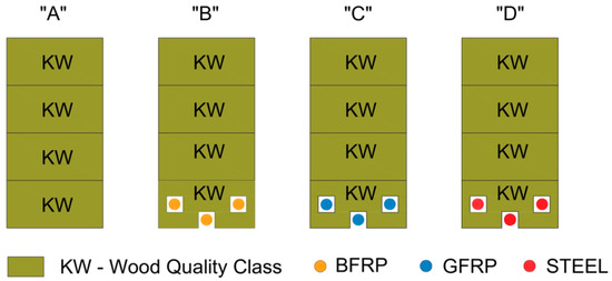
Figure 2.
Scheme for reinforcing glulam beams: A series—unreinforced beams, B series—beams reinforced with pre-stressed basalt rods, C series—reinforced with pre-stressed glass rods, D series—reinforced with pre-stressed steel rods.
All the glulam beams in this study were made as follows:
- The construction lumber was planed into dimensions of 85 × 45 × 3670 mm3.
- Four layers of KW structural lumber were bonded to form a single beam glued together under pressure using glue for 72 h.
- The glued beams were planed into dimensions of 82 × 162 × 3650 mm3.
- The longitudinal grooves measuring 14 × 14 mm2 were cut at a suitable and fixed location for the type of reinforcement.
- The longitudinal grooves and rebar were cleaned under high air pressure. After pouring the epoxy resin, the precompressed steel or composite bar was placed in the groove.
- Before gluing, the joints of the glued wood were cleaned with high-level air. Then, the bars were also cleaned with acetone. The initial compression was created at 10 MPa, and the end anchors were tightened after reaching the assumed value. The prestress force was also checked based on the average values of rod deformation.
- The epoxy glue of the glued beams was cured for a minimum of 7 days before the test.
In the experimental study, a four-point bending test was carried out. In this experiment, the experimental program consisted of a bending test of 20 wooden beams (dimensions 82 × 162 × 3650 mm3) under static loading. A 100 kN machine was used for the strength tests. Mechanical displacement dial gauges were set directly below the position of the beam at mid-span and over a length of 5 h (where h is the height of the cross section). In contrast, extensometer bases were tested on the side of each layer of wood beams along the grain direction and were also placed on implanted steel and composite bars (see Figure 3). In the tests, the deformation of the timber rods was measured using a fixed-base mechanical extensometer of the ‘Demec’ type. After the prestressed steel, BFRP, and GFRP bars were fixed and glued together, the grooves of the reinforced beams were covered on the side with planks of structural lumber. The distance between the supports was 3000 mm, the distance between the actuators was 1000 mm, and the distance between the actuators and the supports was 1000 mm. The actual arrangement of the loads as well as the location of the displacements is shown in Figure 1, while the experimental arrangement is shown in Figure 4.
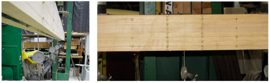
Figure 3.
The distribution of the placement of the inductive sensors along the 5 h and the bases for the strain measurements along the length of the beams.
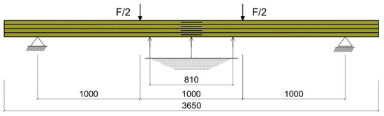
Figure 4.
Experimental set-up of the beams under test (dimensions in the drawing are given in millimeters).
2.3. MES
FEA finite element models of steel-reinforced glulam, BFRP, and GFRP beams were developed with ANSYS 16.0 finite element software using the Static Structural module. Additionally, geometric models of beams were used in the CATIA V5 program. Then, a composite was created consisting of blocks, with supports and points of application of loading forces, lamellas, reinforcing bars, and glue filling the space between the lamella and the bar. The beam model was modeled as three independent parts: wooden beam; GFRP, BFRP, and steel reinforcing bars; and epoxy resin glue. Based on experimental studies, boundary conditions for the support were also applied to the FEM model at the bottom of the beam. The finite element mesh consisted of hexagonal and tetragonal elements. The lamellas and supports were hexagonal elements with dimensions of 10 mm. However, the bars and the glue between the lamellas and around the bars were modeled as tetragonal elements with dimensions of 5 mm (see Figure 5).
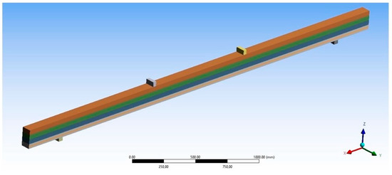
Figure 5.
A numerical FEM model for a reinforced beam.
Numerical data of the strength and elastic properties of the materials used in the model were obtained from experimental studies and are presented in Table 3. The numerical data to create the material models were taken from experimental studies. The wood was modeled as an orthotropic material showing different values of Young’s modulus, Poisson’s modulus, and shear modulus for the three main directions. Poisson’s modulus, Young’s modulus, and shear modulus were determined experimentally for each quality class of structural lumber, as shown in Table 4. The bonded connection between consecutive lamellas was also included in the analysis. The boundary conditions were assumed in the analysis to faithfully represent the bending of the beam. On the upper surfaces of the blocks, two concentrated forces of the same values were applied. The supports, on the other hand, were the lower blocks and spaced further apart. One of the supports acted as a fixed support and the other as a moving support. These assumptions were made by using fixed support for the fixed support and displacement for the movable support (movement of the second block was only possible in the X axis).
Table 3.
The material models for the reinforcing elements.
Table 4.
The material models for wood.
3. Results
The results of the tests are presented in Table 5. The results are given for each set of beams, i.e., series A, B, C, and D beams. In particular, the load carrying capacity and bending stiffness of the beams are shown below as well as the mean values and standard deviations for each group of beams. The tests showed a percentage increase in the maximum load capacity and bending stiffness of reinforced beams of types B, C, and D compared to unreinforced beams of type A.
Table 5.
The results of experimental bending tests.
The percentage increase in maximum load capacity ranged from 27.4% to 58.2%. Based on the study, it was found that the lowest value was achieved by type C beams, while the highest value was achieved by type D beams. At the same time, it can be seen that type D beams with a prestressed steel bar were characterized by the highest percentage increase compared to other reinforced beams. It can therefore be concluded that the maximum load-bearing capacity of wooden beams can be effectively increased using prestressed steel bars.
The MR–displacement curve at mid-span for all types of test beams is shown in Figure 6.
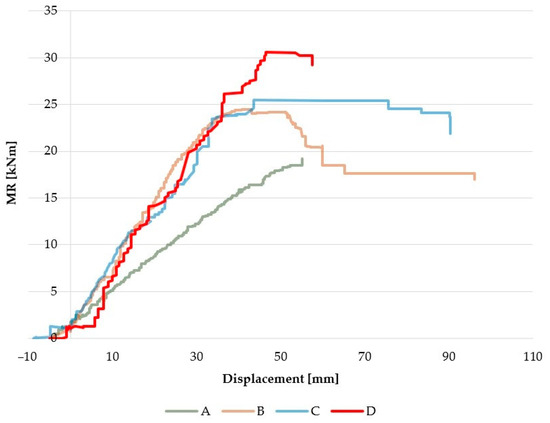
Figure 6.
The MR–displacement curve for all types of beams.
The highest load-bearing capacity of reinforced beams, especially with a reinforcement content of 1.8% in the case of steel, was significantly increased by over 50% compared to unreinforced beams. Unreinforced type A beams showed a linear elastic range in which the slope of the MR–displacement curve was generally constant from the initial loading stage until failure. In contrast, it was different on beams reinforced with steel bars (type D), where the curve had a slightly steeper line than the control beam and the slope of the curve then decreased when a certain load was reached. This indicates that reinforced beams behave pseudo-steeply. Additionally, it can be taken into account that the deflection of prestressed beams decreased compared to unreinforced beams due to the initial prestressing.
The experimental study found that beam reinforcement also increased the stiffness of the timber beams. The stiffness of reinforced beams of types B, C, and D, determined from the average values of five similar beams of each type, increased by 7.8%, 10.1%, and 10.7%, respectively, compared to unreinforced beams (type A). Therefore, it can be concluded from the study that the type of bar influences the percentage increase in the stiffness of the beams. This increase is particularly evident for steel bars and basalt bars compared to unreinforced beams.
In Figure 7 and Figure 8 below, the results are shown for two representative beam types C and D defining the strain distribution in the range of 3–25 kNm. It can be seen that in the experimental tests, all beams failed when the lower wood fibers reached maximum tensile strain. The allowable compressive strain then decreased by 36.6% for type B, 32.9% for type C, and 30.4% for type D. By embedding prestressed steel bars, the coniferous timber transfers loaded better in the compression zone of the beam. This shows that the use of prestressing further exploits the strength of the reinforcement beyond the yield point.
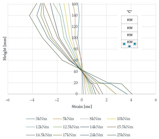
Figure 7.
The distribution of deformations over the height of a C-beam section at mid-span—reinforcement with pre-stressed GFRP rods.
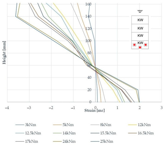
Figure 8.
The distribution of deformations over the height of type D beam section at mid-span—reinforcement with pre-stressed steel bars.
Unreinforced beams, i.e., type A, usually failed in the tension zone at the bottom of the beam (Figure 9). On the other hand, damage to timber in the tension zone was also observed in the majority of reinforced beams (see Figure 9). In addition, beams, especially type D beams with prestressed steel bars, were damaged in shear, e.g., the D-4 beam.
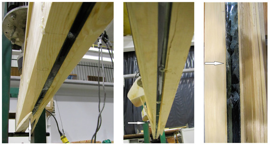
Figure 9.
An example of an image of the destruction of the B-3 beam.
Also shown below in Table 6 is a comparison of the experimental and numerical results. The numerical analysis of the values obtained also showed good correlation with the laboratory analysis. The difference was small, ranging from 4.6% to 5.7%. Above all, a high degree of convergence was obtained, which may be due to the data that was determined from the experimental studies.
Table 6.
A selection of experimental and numerical results for comparison.
Table 7 shows the finite element models that were validated against the experimental data. This is important because it can be used to examine the stress distribution to determine whether the negligible differences in the experimental results were due to the geometry, the reinforcement scheme, or the difference in the mechanical properties according to the wood quality class. Therefore, separate models were developed for the same analysis for identical reinforcement schemes with different reinforcing materials. The numerical analysis of the normal stress values for each class also showed good correlation with the laboratory analysis, and the difference was small.
Table 7.
A selection of experimental and numerical results for comparison of normal stresses in wood and bars for MR = 8 kNm.
4. Discussion
It should be noted that there are different methods for strengthening glulam or other wood-based beams during static bending work. The following methods of strengthening wooden beams are distinguished in the literature:
- Structural protection and reinforcement, consisting of the introduction of additional elements (independent structural reinforcement, suspended structural strengthening system, and reinforcement cooperating with the existing structural system).
- Structural treatments (increasing the technical and operational values of damaged elements).
The most frequently used reinforcements that cooperate with the existing structural system include the following:
- Strengthening wooden beams along their entire length by connecting the side surfaces of the beams with strengthening elements, such as overlays made of boards or logs, steel sections, and introducing reinforcement into the tension zone of the beam.
- Strengthening of the beam fragment, including replacing the damaged part of the beam with a complementary element as well as removing the damaged end of the beam and suspending the ceiling beam with steel stirrups.
- Reinforcement based on combining ceiling beams with a reinforced concrete slab.
- Strengthening beams with other materials, e.g., steel tendons.
Nowadays, there is great interest in strengthening wooden, reinforced concrete, masonry, and steel structures using fiber composites.
It should be noted that despite the fact that reinforcement of wooden structures has existed for over 50 years, only recently has there been an increase in the development of various reinforcement systems.
If we want to increase the load-bearing capacity, loose reinforcement is usually sufficient. However, it should be noted that compared to reinforcement using prestressed FRP systems, it requires a larger amount of FRP material to reach the same level. Therefore, it is also related to the serviceability limit state, and it is also important to prebend them when designing new beams. It is also often important to minimize the total height of the structure in an economic way. Therefore, prestressing wooden beams in the factory would be a very important solution. For example, the method proposed by Lehmann et al. [53,54] using preliminary bending of the wood before assembly may be an interesting approach for producers of glued wood. When the beam requires strengthening in situ, then the gradual compression method developed in Haghani and Al-Emrani [53,55] seems to be a good solution. Likewise, the amount of reinforcement can be reduced using pretensioned lamellas as strengthening systems for nonprestressed elements. In such cases, the material can be used up to 100%. Various laboratory test results can be found in the literature. For example, in the literature [53,56], it has been shown that it is possible to increase the permissible bending stresses by up to 38% for prestressed GFRP glued beams compared to reinforced GFRP glued beams without prestress and an increase of up to approximately 95% compared to unreinforced elements. Anna Halicka et al. [57] showed the results of tests on the strengthening of wooden beams using tensioned CFRP tapes. The study determined the destructive forces, failure mechanisms, and load–deflection relationships in individual rows of beams in comparison to reference beams. Additionally, it was found that it was possible to prestress solid wood beams and reduce their deflection under stress. The first compression tests used glass composite tapes glued between the last and penultimate lamella [58]. To increase the prestressing effect, a beam was constructed by prestressing with several aramid tapes glued transversely into the last lamella [59]. In subsequent tests of glued wood using GFRP rods, it was found that when reinforced in circular grooves, their stiffness increased [60]. A 1.4% reinforcement of the circular grooves in the tension zone resulted in an average increase in stiffness by 11.2% and 13.9% and an average increase in the bending moment of 68% compared to unreinforced beams. Meanwhile, 2.8% reinforcement increased the stiffness by 22% and 29.6% and the average bending moment by 98.5% compared to unreinforced glued beams.
In this study of the A series of beams, all unreinforced beams primarily failed in the tension zone due to fracture of the timber fibers—fiber twist or if there was a defect because of the KW class—in place of natural defects, just as one beam failed in the compression zone. It should be noted that already prestressed and reinforced beams were already failing due to bending and shear. Figure 9 shows the cracking of the timber fibers in the tension zone of a prestressed reinforced beam. It should be noted that the introduction of the BFRP bars also resulted in a change of the failure mode to plastic failure in compression in some beams (B-1 beam). This was very evident, especially in steel reinforced and prestressed beams (D-2 beam). It should also be noted that the tests did not cause the bars to break due to their high strength. Similarly, the epoxy adhesive only became loose, not detached. This could have been caused by the anchoring used at the ends of the bars and the connection of these bars along the axis of the beam.
The results of the experimental tests are also analyzed in Table 5. It can be seen that the failure load had improved very significantly for both reinforced and prestressed glulam beams. The test results are also summarized in Table 4. It can be seen from Table 4 that the ultimate load had improved significantly for both reinforced and prestressed glulam beams. Increases of 58%, 32%, and 27% were achieved for the reinforced prestressed glulam beams. It should be noted that this increase was 58% for steel, 32% for basalt, and 27% for glass compared to unreinforced uncompressed beams, which represents a significant improvement for the same reinforcement ratio. Likewise, in terms of beam deflection, when 1/250 of the beam span was reached, the improvement was even more significant considering glulam prestressed beams. This increase was at the level of 10.7%, 10.1%, and 7.8%. This increase in stiffness was beneficial for strengthening as well as prestressing.
The different levels of improvement in reinforcement efficiency were also related to the different elastic modulus of the reinforcement itself. In the case of prestressed steel bar rods, the failure was more abrupt, with a sudden but significant increase in load capacity and stiffness being achieved. In some beams, there was also shearing of the timber fibers, and compression shear occurred. In the case of beams reinforced with prestressed basalt bars, the failure was also abrupt but less than that of steel; an increase in load capacity of 32% was obtained, but the stiffness was comparable to steel. In the same way, most of the timber fibers got fractured in the tension zone, and some also failed in the compression zone. In the case of prestressed beams with glass reinforcement, significant increases in load capacity and stiffness were also achieved, but failure was most common in the tension zone.
The numerical analysis of the normal stress values of the timber and composite bars in the tension zone also showed very good correlation with the laboratory analysis, as shown in Table 7. It should be noted that in the case of prestressed reinforced elements, for this class, the difference was small. In the same way, the values of the normal stresses in the composite bars were almost equivalent. The resulting small differences between the results obtained from the numerical analysis and the laboratory tests may be due to the fact that wood is a complex organic material exhibiting anisotropy of mechanical properties. There are structural complexities in wood (e.g., irregularities in the structure, wood defects, etc.) because it is a natural element; what affects it is impossible to control. The results obtained from the numerical analysis showed good agreement with the experimental results because materials used in this study were determined on the basis of actual values obtained from experimental tests and were appropriate for each structural friction quality class. Material tests of the analyzed elements were carried out, and average values were determined for each quality class of construction wood, including elastic modulus, shear modulus, and Poisson’s modulus.
5. Conclusions
The experimental, theoretical, and numerical studies conducted in this work shows that the use of prestressed steel and prestressed composite bars can be a reliable way of improving the efficiency of timber beams. The following conclusions were drawn from the experimental and numerical studies:
- In the experimental studies, the increased load capacity of reinforced glulam beams were improved between 27.4% and 58.2% compared to unreinforced beams. In addition, the experimental study also showed improved stiffness of the timber beams by approximately 7.8%, 10.1%, and 10.7% compared to unreinforced beams. A number of factors, including the type of reinforcement used, may influence the improved load-bearing capacity and stiffness of the beams. Thus, beams using prestressed steel bars had the highest strengthening effect. In addition, they showed a tendency towards pseudo-rigidity compared to the elastic linear behavior of unreinforced beams. The damage that occurred during the experimental tests was mainly in the tension zone. Basalt BFRP, glass GFRP, and prestressed steel bars were found to be suitable for reinforcing timber elements of even the highest grade, achieving a significant increase in load capacity and stiffness.
- For the adopted computational and numerical models of bending beams reinforced with prestressed GFRP, BFRP, and steel bars, the effectiveness of the strengthening in terms of stiffness was confirmed; in the numerical models, the values were a little higher than in the laboratory tests. Moreover, it should be noted that numerical analysis is generally used in the design of various reinforcement schemes, with particular emphasis on the configuration of wood quality classes. The slight difference of only 3.1% to 5.7% was due to the fact that all numerical data were obtained from laboratory tests. The Poisson’s modulus, Young’s modulus, and shear modulus were determined for each quality class of structural timber. Moreover, these tests used beams of the highest quality class with significant homogeneity.
- The above research results can be used for numerical calculations in the field of repairs or reinforcements of various degrees, patterns, and types of reinforcement in existing wooden structures as well as for technologies using the tested types of reinforcements in conservation practice. In addition, the use of FRP or steel rods can be an effective and common method for repairing glued beams or trusses in the field. Similarly, the successive development of structures reinforced with FRP rods is related to the improvement of the properties of the composite rods themselves. The greater durability of structures reinforced with FRP rods or the avoidance of costs associated with the operation of steel-reinforced structures justifies the advisability of using these composites.
Author Contributions
Conceptualization, A.W.-P.; methodology, A.W.-P., J.G., F.B. and J.P.; software, A.W.-P., J.G., F.B. and J.P.; validation, A.W.-P., J.G., F.B. and J.P.; formal analysis, A.W.-P., J.G., F.B. and J.P.; investigation, A.W.-P., J.G., F.B. and J.P.; resources, A.W.-P., J.G., F.B. and J.P.; data curation, A.W.-P., J.G., F.B. and J.P.; writing—original draft preparation, A.W.-P., J.G., F.B. and J.P.; writing—review and editing, A.W.-P., J.G., F.B. and J.P.; visualization, A.W.-P., J.G., F.B. and J.P.; supervision, A.W.-P.; project administration, J.G., F.B. and J.P.; funding acquisition, J.G., F.B. and J.P. All authors have read and agreed to the published version of the manuscript.
Funding
This research was supported by Research Projects No. 1/0306/21 of the Slovak Grant Agency and by Research Projects No. 1/0623/21 and No. 1/0630/21.
Institutional Review Board Statement
Not applicable.
Informed Consent Statement
Not applicable.
Data Availability Statement
The data presented in this study are available on request from the corresponding author. The data are not publicly available due to file size limitations.
Conflicts of Interest
The authors declare no conflict of interest.
References
- Alkhudery, H.H.; Al-Tameemi, H.A.; Al-Katib, H.A.A. Experimental and theoretical investigation of the structural behavior of reinforced glulam wooden members by NSM steel bars and shear reinforcement CFRP sheet. Open Eng. 2023, 13, 20220481. [Google Scholar] [CrossRef]
- Vahedian, A.; Shrestha, R.; Crews, K. Experimental and analytical investigation on CFRP strengthened glulam laminated timber beams: Full-scale experiments. Compos. Part B Eng. 2019, 164, 377–389. [Google Scholar] [CrossRef]
- Thorhallsson, E.R.; Hinriksson, G.I.; Snæbjörnsson, J.T. Strength and stiffness of glulam beams reinforced with glass and basalt fibers. Compos. Part B Eng. 2017, 115, 300–307. [Google Scholar] [CrossRef]
- Al-Katib, H.A.A.; Alkhudery, H.H.; Al-Tameemi, H.A. Structural behavior of standard timber beams strengthened using CFRP sheet. Asian J. Civ. Eng. 2022, 23, 727–739. [Google Scholar] [CrossRef]
- Yoresta, F.S.; Nugroho, N. Strengthening of Timber Beam with Cold-Formed Steel Plates. Int. J. Sustain. Constr. Eng. Technol. 2023, 14, 306–314. [Google Scholar] [CrossRef]
- Rescalvo, F.J.; Valverde-Palacios, I.; Suarez, E.; Gallego, A. Experimental and analytical analysis for bending load capacity of old timber beams with defects when reinforced with carbon fiber strips. Compos. Struct. 2018, 186, 29–38. [Google Scholar] [CrossRef]
- Śliwa-Wieczorek, K.; Ostrowski, K.A.; Jaskowska-Lemańska, J.; Karolak, A. The Influence of CFRP Sheets on the Load-Bearing Capacity of the Glued Laminated Timber Beams under Bending Test. Materials 2021, 14, 4019. [Google Scholar] [CrossRef] [PubMed]
- Ghanbari Ghazijahani, T.; Jiao, H.; Holloway, D. Composite Timber Beams Strengthened by Steel and CFRP. J. Compos. Constr. 2017, 21, 04016059. [Google Scholar] [CrossRef]
- Dar, M.A.; Subramanian, N.; Anbarasu, M.; Carvalho, H.; Dar, A.R. Effective Strengthening of Timber Beams: Experimental Investigation. Prac. Period. Struct. Des. Constr. 2021, 26, 04020042. [Google Scholar] [CrossRef]
- Falk, L.H. Wood as a sustainable building material. In Wood Handbook–Wood as an Engineering Material, Centennial Edition; Ross, R.J., Ed.; Department of Agriculture, Forest Service, Forest Products Laboratory: Madison, WI, USA, 2010; p. 1. [Google Scholar]
- Uzel, M.; Togay, A.; Anil, Ö.; Söğütlü, C. Experimental investigation of flexural behavior of glulam beams reinforced with different bonding surface materials. Constr. Build. Mater. 2018, 158, 149–163. [Google Scholar] [CrossRef]
- Junior, A.F.d.V.; Vicente, W.M. Innovative Approach for Enhancing GLULAM Performance with Reinforcing Steel Bars: A BESO-based Study. Lat. Am. J. Solids Struct. 2023, 20, e503. [Google Scholar] [CrossRef]
- Kremer, P.D.; Symmons, M.A. Mass timber construction as an alternative to concrete and steel in the Australia building industry: A PESTEL evaluation of the potential. Int. Wood Prod. J. 2015, 6, 138–147. [Google Scholar] [CrossRef]
- Lall, J.; Oh, T.; Shilstone, M. Central City Association, White Paper: Mass Timber A Faster, More Affordable, and More Sustainable Way To Build Housing, Technical Report; Central City Association: Los Angeles, CA, USA, 2019. [Google Scholar]
- Gustavsson, L.; Pingoud, K.; Sathre, R. Carbon Dioxide Balance of Wood Substitution: Comparing Concrete- and Wood-Framed Buildings. Mitig. Adapt. Strat. Glob. Chang. 2006, 11, 667–691. [Google Scholar] [CrossRef]
- Huang, S.; Yan, L.; Kasal, B. Flexural behaviour of wood beams strengthened by flax-glass hybrid FRP subjected to hygrothermal and weathering exposures. Constr. Build. Mater. 2023, 365, 130076. [Google Scholar] [CrossRef]
- Wdowiak-Postulak, A. Strengthening of Structural Flexural Glued Laminated Beams of Ashlar with Cords and Carbon Laminates. Materials 2022, 15, 8303. [Google Scholar] [CrossRef] [PubMed]
- Socha, T.; Kula, K.; Denisiewicz, A.; Lesiuk, G.; Błażejewski, W. Rheological Relaxation of OSB Beams Reinforced with CFRP Composites. Materials 2021, 14, 7527. [Google Scholar] [CrossRef]
- Wdowiak-Postulak, A. Basalt Fibre Reinforcement of Bent Heterogeneous Glued Laminated Beams. Materials 2021, 14, 51. [Google Scholar] [CrossRef]
- Chybiński, M.; Polus, Ł. Structural Behaviour of Aluminium–Timber Composite Beams with Partial Shear Connections. Appl. Sci. 2023, 13, 1603. [Google Scholar] [CrossRef]
- Wdowiak-Postulak, A. Ductility load capacity and bending stiffness of Scandinavian pine beams from waste timber strengthened with jute fibres. Drewno 2022, 65. [Google Scholar] [CrossRef]
- Chybiński, M.; Polus, Ł. Theoretical, experimental and numerical study of aluminium-timber composite beams with screwed connections. Constr. Build. Mater. 2019, 226, 317–330. [Google Scholar] [CrossRef]
- Wdowiak-Postulak, A. Numerical, theoretical and experimental models of the static performance of timber beams reinforced with steel, basalt and glass pre-stressed bars. Compos. Struct. 2023, 305, 116479. [Google Scholar] [CrossRef]
- Wdowiak-Postulak, A.; Bahleda, F.; Prokop, J. An Experimental and Numerical Analysis of Glued Laminated Beams Strengthened by Pre-Stressed Basalt Fibre-Reinforced Polymer Bars. Materials 2023, 16, 2776. [Google Scholar] [CrossRef] [PubMed]
- Kawecki, B.; Sumorek, A. Study on Profitability of Combining Wood and CFRP into Composite Based on Mechanical Performance of Bent Beams. Appl. Sci. 2022, 12, 10304. [Google Scholar] [CrossRef]
- Wdowiak-Postulak, A.; Wieruszewski, M.; Bahleda, F.; Prokop, J.; Brol, J. Fibre-Reinforced Polymers and Steel for the Reinforcement of Wooden Elements—Experimental and Numerical Analysis. Polymers 2023, 15, 2062. [Google Scholar] [CrossRef] [PubMed]
- Chybiński, M.; Polus, Ł. Experimental and numerical investigations of aluminium-timber composite beams with bolted connections. Structures 2021, 34, 1942–1960. [Google Scholar] [CrossRef]
- Kawecki, B. Dobór Parametrów Modeli Obliczeniowych Pełnych Dźwigarów z Kompozytów Drewno-Polimerowych Zbrojonych Włóknami. Ph.D. Thesis, Lublin University of Technology, Lublin, Poland, 2020. [Google Scholar]
- Nadir, Y.; Nagarajan, P.; Ameen, M.; M, M.A. Flexural stiffness and strength enhancement of horizontally glued laminated wood beams with GFRP and CFRP composite sheets. Constr. Build. Mater. 2016, 112, 547–555. [Google Scholar] [CrossRef]
- Bal, B.C. Flexural properties, bonding performance and splitting strength of LVL reinforced with woven glass fiber. Constr. Build. Mater. 2014, 51, 9–14. [Google Scholar] [CrossRef]
- Zhang, W.; Yang, P.; Cao, Y.; Yu, P.; Chen, M.; Zhou, X. Evaluation of fiber surface modification via air plasma on the interfacial behavior of glass fiber reinforced laminated veneer lumber composites. Constr. Build. Mater. 2020, 233, 117315. [Google Scholar] [CrossRef]
- Omare, H. Timber Beam Steel Reinforced and Plastic Design. Available online: https://www.researchgate.net/publication/373864635_Timber_Beam_Steel_Reinforced_and_Plastic_Design (accessed on 30 September 2023).
- Maglad, A.M.; Mansour, W.; Fayed, S.; Tayeh, B.A.; Yosri, A.M.; Hamad, M. Experimental Study of the Flexural Behaviour of RC Beams Made of Eco-friendly Sawdust Concrete and Strengthened by a Wooden Plate. Int. J. Concr. Struct. Mater. 2023, 17, 49. [Google Scholar] [CrossRef]
- Gand, A.K.; Yeboah, D.; Khorami, M.; Olubanwo, A.O.; Lumor, R. Behaviour of strengthened timber beams using near surface mounted Basalt Fibre Reinforced Polymer (BFRP) rebars. Eng. Solid Mech. 2018, 6, 341–352. [Google Scholar] [CrossRef]
- Borri, A.; Corradi, M. Strengthening of timber beams with high strength steel cords. Compos. Part B Eng. 2011, 42, 1480–1491. [Google Scholar] [CrossRef]
- Soriano, J.; Pellis, B.P.; Mascia, N.T. Mechanical performance of glued-laminated timber beams symmetrically reinforced with steel bars. Compos. Struct. 2016, 150, 200–207. [Google Scholar] [CrossRef]
- Jasieńko, J.; Nowak, T.P. Solid timber beams strengthened with steel plates—Experimental studies. Constr. Build. Mater. 2014, 63, 81–88. [Google Scholar] [CrossRef]
- Borri, A.; Corradi, M.; Speranzini, E. Reinforcement of wood with natural fibers. Compos. Part B Eng. 2013, 53, 1–8. [Google Scholar] [CrossRef]
- Chen, S.; Wei, Y.; Peng, D.; Zhao, K.; Hu, Y. Experimental investigation of timber beams strengthened by bamboo scrimber with anchorage structure. Structures 2021, 33, 1–11. [Google Scholar] [CrossRef]
- Franzoni, L.; Lebée, A.; Lyon, F.; Forêt, G. Closed-form solutions for predicting the thick elastic plate behavior of CLT and timber panels with gaps. Eng. Struct. 2018, 164, 290–304. [Google Scholar] [CrossRef]
- Xian, G.; Guo, R.; Li, C. Combined effects of sustained bending loading, water immersion and fiber hybrid mode on the mechanical properties of carbon/glass fiber reinforced polymer composite. Compos. Struct. 2021, 281, 115060. [Google Scholar] [CrossRef]
- Lal, H.M.; Uthaman, A.; Li, C.; Xian, G.; Thomas, S. Combined Effects of Cyclic/Sustained Bending Loading and Water Immersion on the Interface Shear Strength of Carbon/Glass Fiber Reinforced Polymer Hybrid Rods for Bridge Cable. Constr. Build. Mater. 2022, 314, 125587. [Google Scholar] [CrossRef]
- PN-D-94021:2013-10; Coniferous Construction Timber Sorted by Strength Methods. Polish Committee for Standardization: Warsaw, Poland, 2013.
- PN-EN 408+A1:2012; Timber Structures—Structural Timber and Glued Laminated Timber—Determination of Some Physical and Mechanical Properties. Polish Committee for Standardization: Warsaw, Poland, 2012.
- PN-77/D-04229; Wood. Determination of Compressive Strength along the Fibers. Polish Committee for Standardization: Warsaw, Poland, 1977.
- PN-79/D-04102; Wood—Determination of Compressive Strength along the Grain. Polish Committee for Standardization: Warsaw, Poland, 1979.
- PN-79/D-04105; Wood. Determination of Shear Strength along Fibers. Polish Committee for Standardization: Warsaw, Poland, 1979.
- PN-81/D-04107; Wood. Determination of Tensile Strength along Fibers. Polish Committee for Standardization: Warsaw, Poland, 1981.
- PN-81/D-04108; Wood. Determination of Tensile Strength across the Fibers. Polish Committee for Standardization: Warsaw, Poland, 1981.
- PN-H-93220:2018-02; Concrete Reinforcement Steel—Weldable Reinforcing Steel B500SP—Ribbed Bars and Wire Rod. Polish Committee for Standardization: Warsaw, Poland, 2018.
- GOST 31938:2012; Fiber-Reinforced Polymer Bar for Concrete Reinforcement—General Specifications. Interstandard: Moscow Russia, 2012.
- Available online: https://www.sp-reinforcement.pl/sites/default/files/field_product_col_doc_file/resin55_hp_polska_ver20190523.pdf (accessed on 31 March 2019).
- Kliger, I.R.; Haghani, R.; Brunner, M.; Harte, A.M.; Schober, K.-U. Wood-based beams strengthened with FRP laminates: Improved performance with pre-stressed systems. Eur. J. Wood Wood Prod. 2016, 74, 319–330. [Google Scholar] [CrossRef]
- Lehmann, M.; Properzi, M.; Pichelin, F.; Triboulet, P. Pre-stressed FRP for the in situ strengthening of timber structures. In Proceedings of the World Conference on Timber Engineering (WCTE 2006), Portland, OR, USA, 6–10 August 2006. [Google Scholar]
- Haghani, R.; Al-Emrani, M. A new method and device for application of bonded prestressed FRP laminates. In Proceedings of the Second International Conference on Advances I Civil and Structural Engineering, Kuala Lampur, Malaysia, 20–21 December 2014; ISBN 978-1-63248-035-4. [Google Scholar]
- Dagher, H.; Gray, H.; Davids, W.; Silva-Hernandez, R.; Nader, J. Variable prestressing of FRP-reinforced glulam beams: Methodology and behaviour. In Proceedings of the World Conference on Timber Engineering (WCTE 2010), Riva del Garda, Italy, 20–24 June 2010. [Google Scholar]
- Halicka, A.; Ślósarz, S. Strengthening of timber beams with pretensioned CFRP strips. Structures 2021, 34, 2912–2921. [Google Scholar] [CrossRef]
- Guan, Z.; Rodd, P.; Pope, D. Study of glulam beams pre-stressed with pultruded GRP. Comput. Struct. 2005, 83, 2476–2487. [Google Scholar] [CrossRef]
- Yahyaei-Moayyed, M.; Taheri, F. Creep response of glued-laminated beam reinforced with pre-stressed sub-laminated composite. Constr. Build. Mater. 2011, 25, 2495–2506. [Google Scholar] [CrossRef]
- Raftery, G.M.; Whelan, C. Low-grade glued laminated timber beams reinforced using improved arrangements of bonded-in GFRP rods. Constr. Build. Mater. 2014, 52, 209–220. [Google Scholar] [CrossRef]
Disclaimer/Publisher’s Note: The statements, opinions and data contained in all publications are solely those of the individual author(s) and contributor(s) and not of MDPI and/or the editor(s). MDPI and/or the editor(s) disclaim responsibility for any injury to people or property resulting from any ideas, methods, instructions or products referred to in the content. |
© 2023 by the authors. Licensee MDPI, Basel, Switzerland. This article is an open access article distributed under the terms and conditions of the Creative Commons Attribution (CC BY) license (https://creativecommons.org/licenses/by/4.0/).