Article

Superelastic Shape Memory Alloy Honeycomb Damper

1
Key Laboratory of Earthquake Engineering and Engineering Vibration, Institute of Engineering Mechanics, China Earthquake Administration, Harbin 150010, China
2
Key Laboratory of Earthquake Disaster Mitigation, Ministry of Emergency Management, Harbin 150010, China
3
Department of Civil Engineering, Guangzhou University, Guangzhou 510006, China
*
Authors to whom correspondence should be addressed.
Appl. Sci. 2023, 13(24), 13154; https://doi.org/10.3390/app132413154
Submission received: 8 November 2023 / Revised: 2 December 2023 / Accepted: 7 December 2023 / Published: 11 December 2023

Abstract

:
The relative displacements between the girders and piers of isolated bridges during intense earthquakes are usually so large that traditional restrainers cannot accommodate the resulting deformation. A novel superelastic shape memory alloy (SMA) honeycomb damper (SHD) is proposed as a means to combine the large strain capacity of SMA and the geometrical nonlinear deformation of honeycomb structures. As a result, the large deformation capacity of the novel damper satisfies the requirements for bridge restrainers. The proposed device consists of a superelastic shape memory alloy (SMA) honeycomb structure, which enables a self-centering capability, along with steel plates that serve to prevent the buckling of the SMA honeycomb. An examination of the SHD was undertaken initially from theoretical perspectives. A multi-cell SHD specimen was subsequently manufactured and evaluated. Following this, numerical simulation analyses of the SHDs using a three-dimensional high-fidelity finite element model were employed to examine the experimental results. In the end, a technique for improving the SHD was suggested. The results indicate that the SHD is able to demonstrate superior self-centering capabilities and stable hysteretic responses when subjected to earthquakes.

1. Introduction

Numerous seismic incidents have provided evidence that bridges with simple supports are susceptible to unseating failure as a result of excessive displacements between the piers and girders [1,2,3,4]. In addition to unseating failure, the intractable problem of dynamic impact between the load-bearing members of bridges during intense earthquakes poses a threat to the structural integrity of the bridges and consequently compromises their resistance to seismic events [1,4]. In order to address these challenges, steel-based restrainers were employed to restrict the deformation of structures [5,6,7,8]. However, the displacement capacity of these restrainers is relatively small. As a result, the bridge’s substructure may be subjected to a substantial instantaneous load and subsequently collapse during a strong or near-fault earthquake.
To enhance the seismic resistance performance of steel-based restrainers, Matteis et al. [9] proposed a steel buckling-inhibited shear panel. In addition, cellular structures have gained considerable interest in engineering applications due to the distinctive energy absorption properties and high stiffness-to-mass ratios that they offer in comparison to metallic restrainers [10,11,12]. Javanmardi et al. [13] developed a hexagonal honeycomb steel damper (HHSD) which is composed of steel plates with multiple cellular structures and two anchors that distribute the load. An assessment of the device’s performance under quasi-static cyclic conditions indicates that the proposed HHSD possesses a remarkable capacity for energy dissipation and a wide range of ductility.
There are also proposals for shape memory alloy (SMA) restrainers that can withstand significant displacement and function as energy dissipation devices [5,14,15,16,17,18,19,20,21,22,23,24,25]. Re-strainers can demonstrate high fatigue resistance, energy consumption, anti-corrosion, and self-centering abilities with the use of SMA material [26,27,28,29,30]. Therefore, SMAs are regarded as the optimal material for bridge restrainers. They are capable of reshaping to their initial configuration following a 7% strain deformation, and their characteristic flag-shaped hysteretic behavior allows them to dissipate input energy when loaded [29,31,32,33,34]. An in-plane deformation behavior analysis and buckling mechanism analysis were conducted by Michailidis et al. [10] on a Ni-Ti SMA structure with narrow walls. It was observed that the honeycomb structure retains its capacity for self-recovery even after undergoing substantial deformation, provided that the strain of the SMA material remains below 7% (ultimate recoverable strain of SMA material). This affords the honeycomb structure a notable advantage in that it can withstand a maximum macro strain of 41.7%.
In this paper, a self-centering SMA honeycomb damper (SHD) is proposed, which utilizes the geometrical nonlinearity of honeycomb structures and the superelastic nature of SMA materials to provide large-stroke capacity. Its overall strain is much larger than the local strain [13,35,36]. In the introduction, the configuration and operational mechanism of SHD are described. A specimen of SHD is subsequently fabricated and evaluated. A discussion follows the results. Experimental results are then used to validate a three-dimensional finite element model of the specimen. Furthermore, the impact of wall thickness on the properties of the SHD is examined through the implementation of parametric analyses. Additionally, a method to improve the deformation capacity of the SHDs is suggested at last.

2. Superelastic SMA Honeycomb Damper

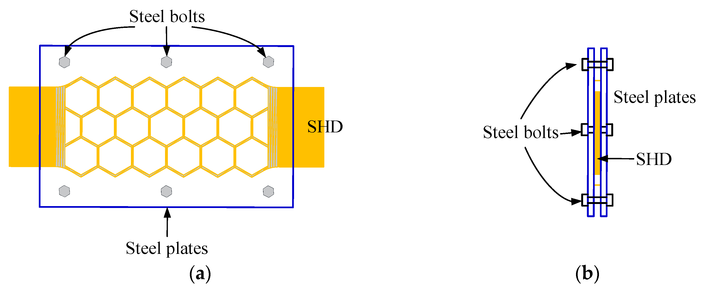
2.1. Design Principle and Configuration

The honeycomb, as depicted in Figure 1, possesses a hexagonal configuration. Due to its thin walls and porous interiors, it exhibits a substantial capacity for deformation when stretched or compressed transversely due to its geometric nonlinearity. Research has demonstrated that a thin-walled SMA honeycomb structure is capable of achieving an overall strain of 60% [10]. Motivated by this phenomenon, we proposed a superelastic SMA honeycomb damper in an effort to enhance the deformation of superelastic SMA restrainers through their geometrical nonlinearity.
Figure 2 depicts a schematic of the proposed superelastic shape memory alloy (SMA) honeycomb damper (SHD). It consists of two steel plates that encase the superelastic SMA honeycomb plate, which provides energy dissipation and self-centering capabilities. When the restrainer is compressed, the out-of-plane deformation of the SHD will be restricted by the steel plates. The dimensions of the SHD are correlated with the cells in the longitudinal and transverse orientations.

2.2. Working Mechanism

The working mechanism of SHD is depicted in Figure 3. The deformation process can be characterized in four stages.
Initially, when the superelastic SMA honeycomb plate is compressed, its geometric shape undergoes non-linear deformation and compressive strain is generated in the SMA components. The steel plates will restrict the out-of-plane buckling of the SMA honeycomb plate. The presence of geometrical nonlinearity in the superelastic SMA plates enhances their ability to sustain deformation. A macro strain on the damper that exceeds 7% is achievable. Subsequently, the SMA honeycomb plate will revert to its initial configuration due to the superelastic characteristic of the SMA material once the compressive force is removed.
When subjected to tension, the superelastic SMA honeycomb plate experiences elongation in its geometrical configuration and the formation of tensile strain in the SMA materials. The deformation capacity of the superelastic SMA plates is further enhanced by their geometrical nonlinearity. Ultimately, when the load is removed, the damper will return back to its original configuration due to the superelastic nature of the SMA materials.

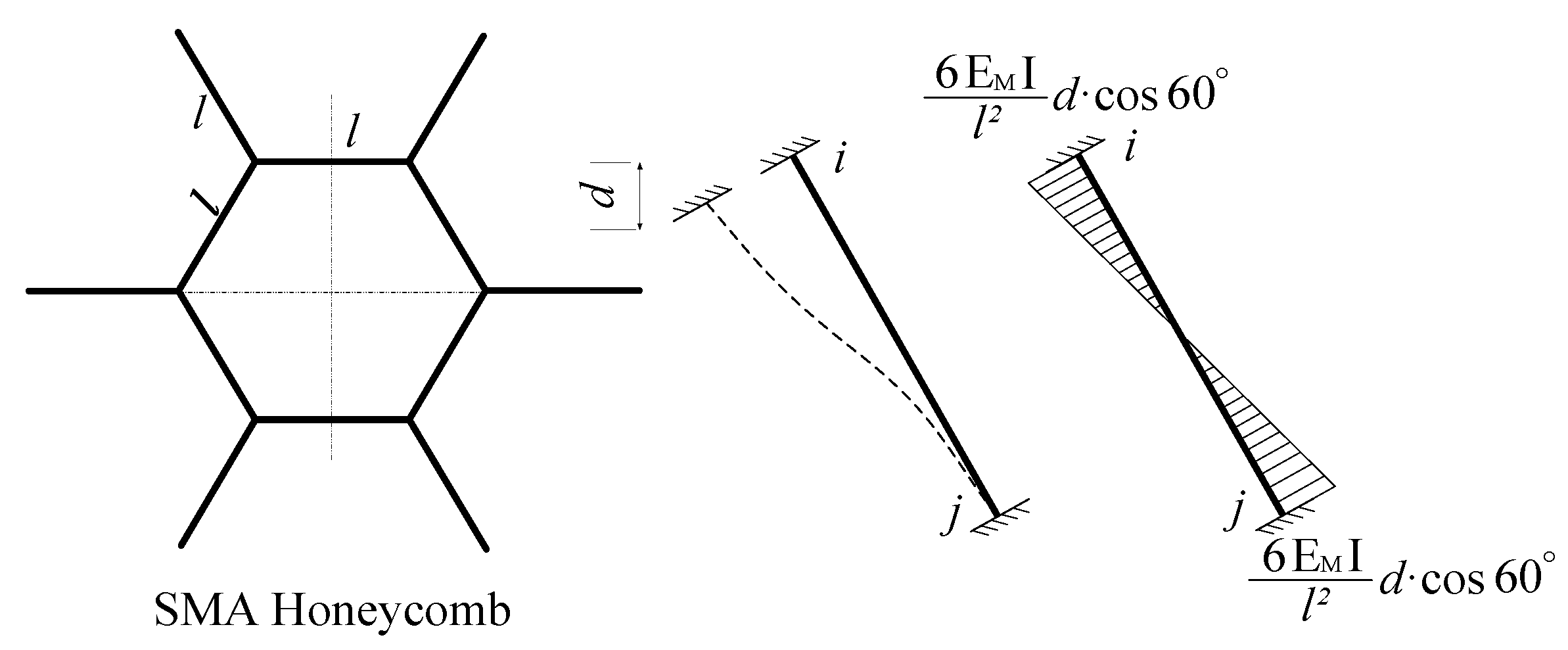
2.3. Theoretical Analysis of a Singular Hexagonal Cell

Figure 4 illustrates a regular hexagonal cell that originates from a honeycomb structure. The figure illustrates that the cell wall has a length of l and a thickness of Lh. The cell undergoes a reshaping process through bending when subjected to an in-plane load (specifically, along the y-axis in this study). As a result, each cell wall can be regarded as a nonlinear beam capable of withstanding significant displacements and rotations [10].
According to the local coordinate system depicted in Figure 4, the honeycomb beam is simplified as a straight beam with a thickness of Lh and a length of l. The beam will bend and move when the honeycomb is loaded (point a to point b). v(x) and h(x) are used to express the displacement vector of the points along the longitudinal and transverse directions. The Euler–Bernoulli beam theory postulates that the cross-section of the small strain beam stays perpendicular to the central axis both before and after deformation. In other words, when the beam experiences warping and transverse shear deformation, the transverse strain can be disregarded, and the plane stays flat and perpendicular to the central axis after deformation. According to the above assumption, the strain of any point with an initial local coordinate (x, y) is given by:
ε x , y = γ x + y k x
where γ(x) is the axial strain function of each point on the central axis and k(x) is the bending curvature. The axial strain, γ(x), and bending curvature, k(x), can be computed by the vertical and horizontal displacement components as
γ x = 1 + d h d x 2 + d v d x 2 1
k x = d v d 2 h d x d x 2 1 + d h d x d 2 v d x 2 1 + d h d x 2 + d v d x 2
where v(x) and h(x) are the vertical and horizontal displacement components, respectively.
The internal virtual work contribution of each node in the weak form of the equilibrium equation can be written as:
δ W l I = 0 1 N δ e + M δ k d x
N L h / 2 L h / 2 σ d y
M L h / 2 L h / 2 σ y d y
where N(x) and M(x) are the combined axial forces and bending moments on the honeycomb wall, respectively, and σ is the axial stress on the honeycomb wall. Corresponding to the Euler–Lagrange equations of Equations (1)–(3), the consistency between them and the equilibrium equation has been proved in detail in the literature [10].
It should be stated that such a three-dimensional deformation process can be completely solved by the method proposed by Marmo et al. [37].

3. Experimental Test
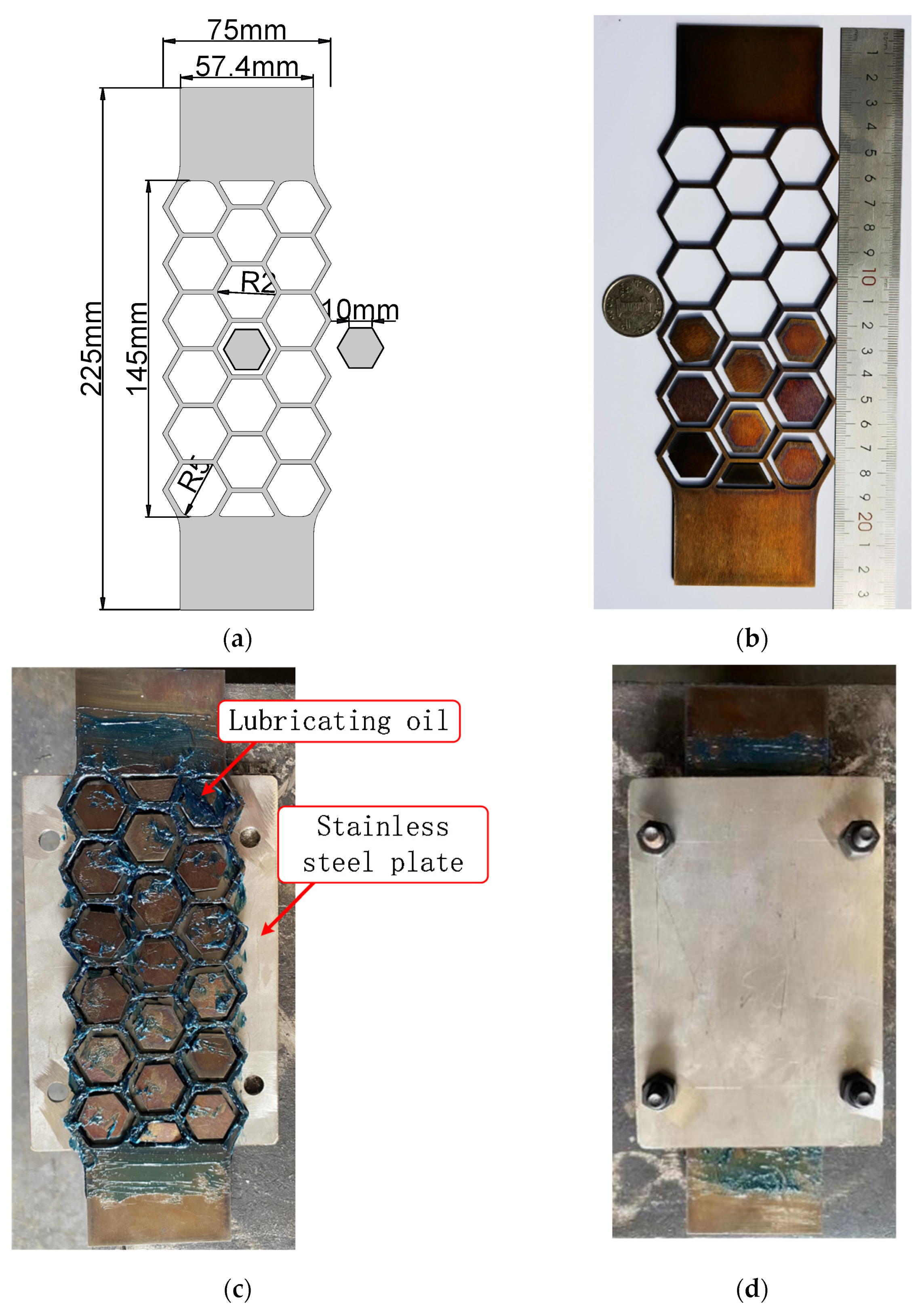
3.1. Specimen

A prototype of the SMA honeycomb damper is conceptualized and produced, as illustrated in Figure 5a, on the basis of the parameter analyses of the SHD. The specimen consists of a series of internal hexagonal blocks, a shape memory alloy (SMA) honeycomb plate, and two stainless-steel plates. The damper is equipped with internally installed solid hexagonal blocks that function as displacement-limiting devices. The stainless-steel plates have dimensions of 100 mm width, 150 mm height, and 5 mm depth. The steel bolts have a diameter of 6 mm.
A graded wall thickness of the honeycomb structure was implemented in order to avert the premature fracture of the SMA materials. Subsequent layers had respective wall thicknesses of 1.5 mm and 2 mm for the initial and subsequent layers. The SMA hexagonal core plates were inserted into each cell with spaces left for SHD deformation in order to prevent the structure from entirely buckling.
Initially, a nitinol shape memory alloy (SMA) plate measuring 225 mm in length and 75 mm in width underwent a heat treatment process at a temperature of 400 °C for a duration of 30 min. It has been reported that SMA bars subjected to this thermal treatment exhibited remarkable superelasticity [38]. Subsequently, the SMA honeycomb and SMA hexagonal core plates were precisely cut from the original plate using a molybdenum wire. Following that, the hexagonal core plates of the shape memory alloy (SMA) were affixed within the SMA honeycomb structure, ensuring that any spaces or voids were adequately filled with lubricating oil. Finally, the SMA honeycomb and core plates were enveloped by a pair of stainless-steel plates, securely fastened together using steel bolts.

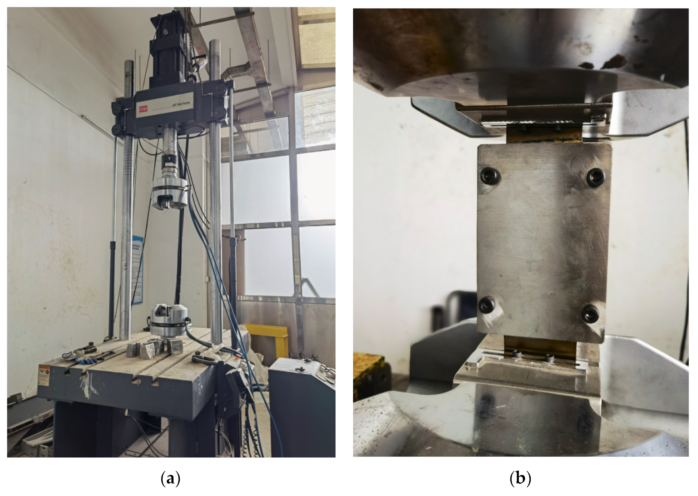
3.2. Test Setup and Loading Procedure

A servo-hydraulic system, MTS 322, was utilized. As illustrated in Figure 6a, it possesses the ability to exert compressive and axial cyclic tensile loads on specimens. The specimen can be adequately tested due to its grip clearance of 2057 mm and force capacity of 500 kN.
The specimen was affixed using the upper and lower clamping arms of the MTS servo-hydraulic system, as illustrated in Figure 6b. Subsequently, a pseudo-static displacement load procedure was performed at a strain rate of 0.00025/s via the upper clamping arm. The displacement loading procedure commences with an amplitude of 2 mm, increasing by 2 mm at each stage of loading until the specimen fractures. A single cycle loading was carried out for every amplitude of displacement to avoid early fracture. The displacements and forces were documented through the test machine’s data-acquiring system.

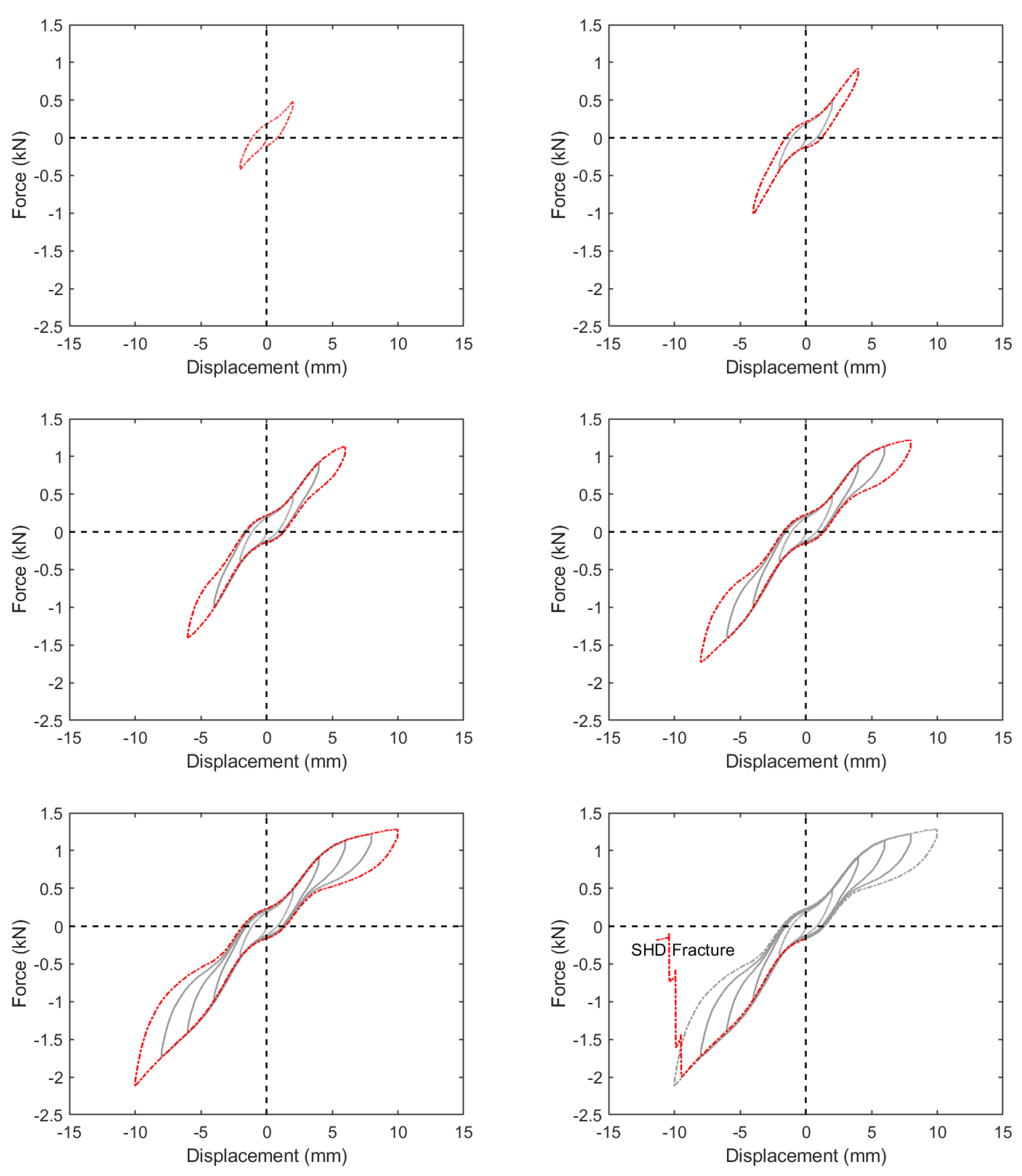
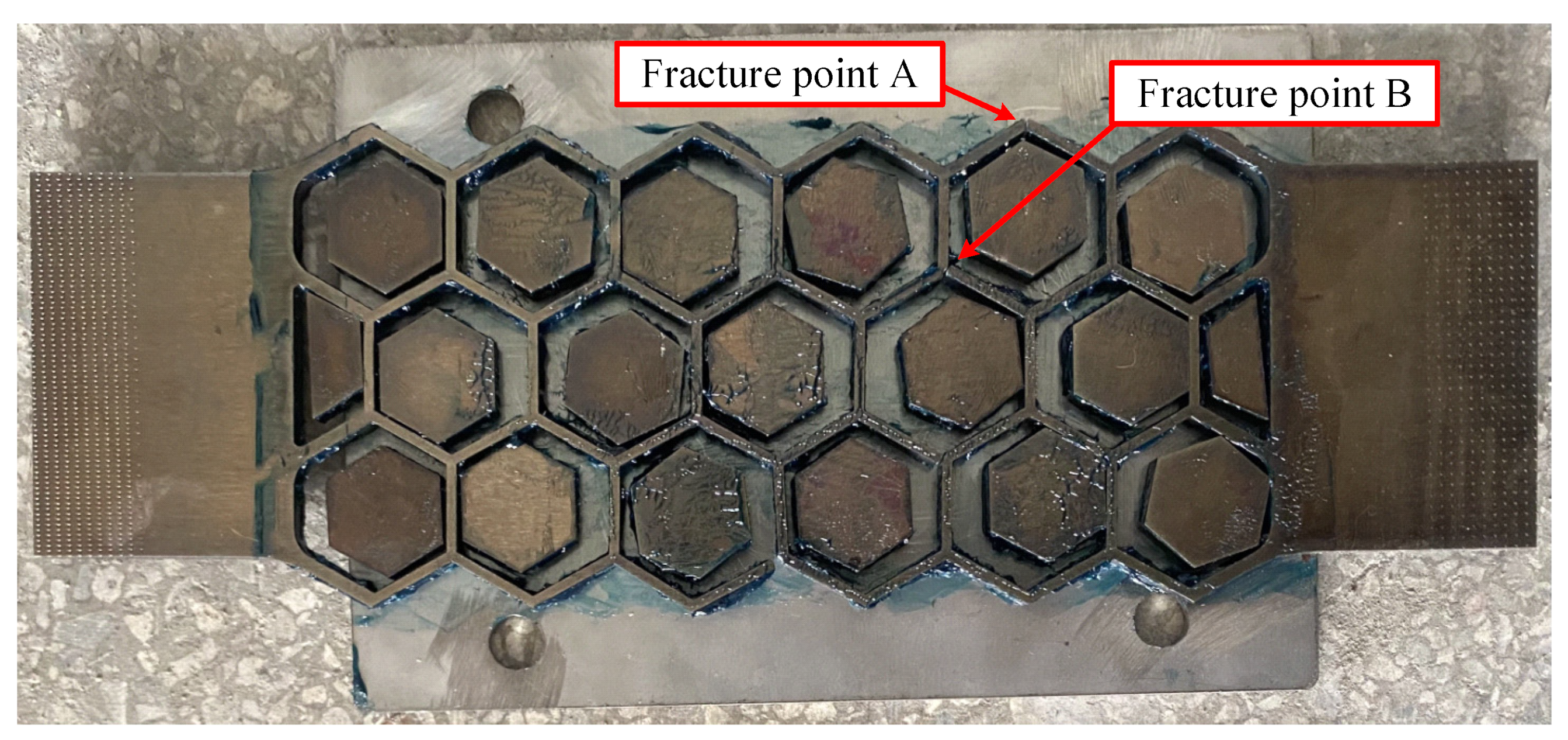
3.3. Experimental Results

Figure 7 illustrates the force-displacement relationship of the specimen, revealing responses in the form of a stable flag-shape. The red lines represent new cycle while the grey lines represent finished cycles. This suggests that the SHD maintains a steady hysteretic performance. The static residual displacement is determined to be 1.5 mm in tension and 1.9 mm in compression, respectively, when the specimen is subjected to a 10 mm displacement loading amplitude. This indicates that the SHD possesses an exceptional capacity for self-centering. The specimen demonstrates a macroscopic fracture strain of 6.9%, as determined by dividing the extended length by the net length of the honeycomb structure, which measures 145 mm. Nevertheless, this fracture strain slightly surpasses that which is typically observed in superelastic SMA plates or bars (less than 6% [24]). It should be noted that a discrepancy of at least 10% exists between the fracture strain observed in the experiment and the strain of the design objective.
Figure 8 illustrates the different mechanical characteristics of the specimen as displacement-loading increases. The maximum forces are adopted at the point of maximum displacement during each loading cycle. The secant stiffness is defined as the ratio of the maximum forces to the maximum displacement. The dissipated energy, ED, is defined as the integral of the area contained by the hysteretic curve throughout each cycle. The equivalent viscous damping ratio is computed as:
ξ e q = E D 4 π E s 0
where Es0 represents the energy dissipated by a linear system when subjected to the same maximum force and displacement throughout each half-cycle of the loading procedure.
The maximal forces and secant stiffness of the specimen under tension are found to be smaller compared to the values obtained in compression. The origin of this phenomenon is attributed to the increased compressive stress exhibited by SMA materials compared to their tensile stress. As the displacement amplitude increases, the amount of dissipated energy also increases. However, the equivalent viscous damping ratio initially decreases and then marginally increases after a displacement of 6 mm. This suggests that the specimen has a steady ability to dissipate energy.
The fracture parts are situated at the outermost part of the honeycomb cell’s sharp edge and one of its interior connecting nodes (see Figure 9). Based on the observed fracture morphology of the specimen, it can be inferred that the failure occurred due to a notable stress concentration at the sharp edge during the tensioning or compressing processes. Shape memory alloys (SMA) exhibit a pattern of metal fatigue and the formation of microcracks following cyclic tension and compression. Moreover, microcracks tend to develop fast during the loading process, which ultimately results in the fracture of the specimen.

4. Numerical Simulation of SHD

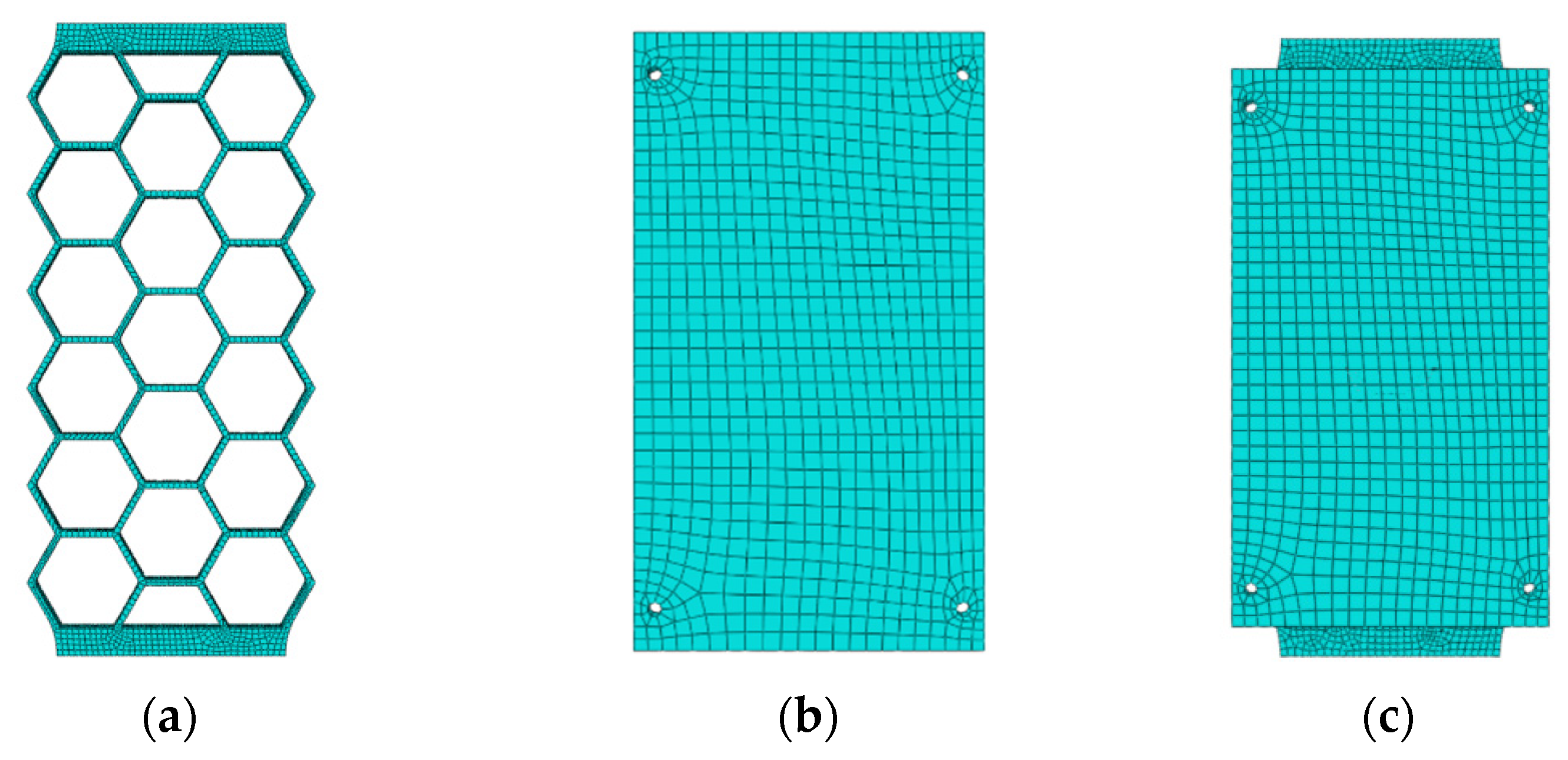
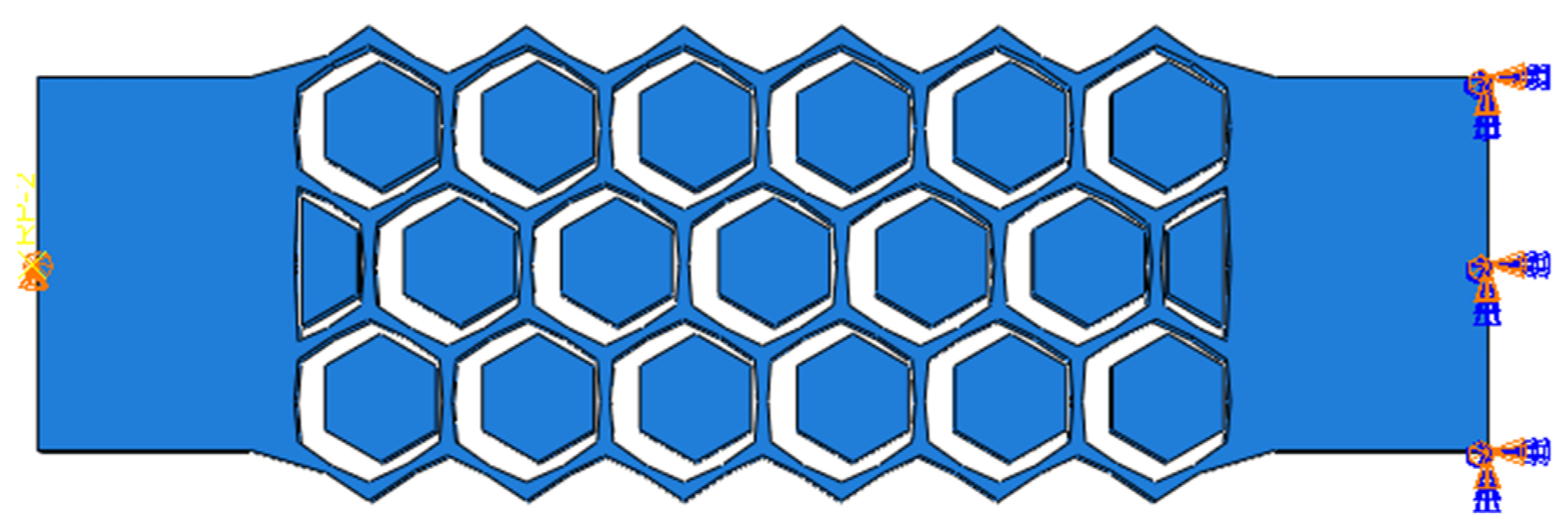
4.1. Finite Element Model

A three-dimensional finite element (FE) model of the SHD was created using the Abaqus 2021 software package, as depicted in Figure 10 [39]. The steel material was modeled using an elastic-perfect plastic material, whereas the SMA materials were modeled using a superelastic material with strain hardening. The specific characteristics of the SMA material are determined according to the reference [19]. A C3D8R brick element with 8 nodes was utilized to model the SMA honeycomb, steel plates, and steel bolts. A study was conducted to examine the effect of the size of the elements on both the computational energy and the accuracy of the results. Finally, a mesh size of 1 mm was chosen for the SMA honeycomb, while a mesh size of 5 mm was selected for the steel plate. It should be noted that utilizing a Vaiana–Rosati model has the potential to accelerate the process of nonlinear dynamic analysis [40]. The interaction between the steel plates and shape memory alloy (SMA) honeycomb was modeled as a hard contact condition, with a friction coefficient of 0.3, which was adopted by comparing the empirical findings with the simulated outcomes. In order to maintain consistency with the experimental condition, the lower surface of the SHD model was fixed, while a displacement loading procedure was applied to a reference point that was connected to the upper surface of the model.

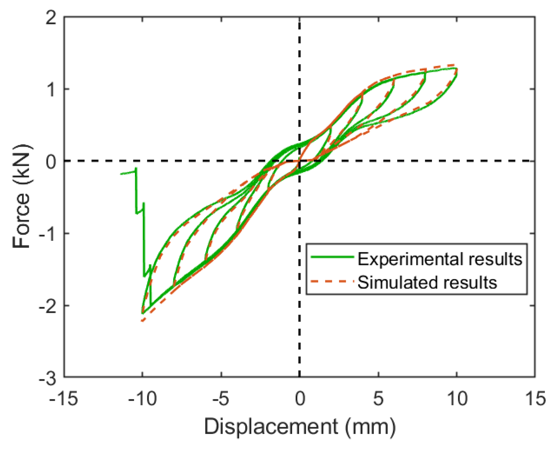
4.2. Experimental and Simulated Results

In Figure 11, a comparison is made between the hysteresis responses of the SHD obtained from experimental data and those obtained from simulation. The simulated replies demonstrate a strong capacity for accurately predicting experimental results.
Figure 12 depicts the strain distribution of the honeycomb plate at a displacement of 12 mm upon fracture. The localization of maximal strain in the specimen is evident at the corners, precisely where the fracture occurred, as illustrated in Figure 8. The largest strain observed is 10.62%, which is significantly greater in magnitude compared to the fracture strain of 7%. Consequently, the specimen experienced fracture at this particular juncture. Nevertheless, the strain in the majority of the cell walls is below 1.77%. This suggests that the bending of cell walls primarily occurs at the corners and that the full potential of the superelasticity of cell walls is not being utilized. Figure 12a illustrates that the stress in the middle region of the cell walls is lower than the Martensite start stress, which is 418 MPa. This suggests that the superelasticity of the SMA material in these regions is not fully used.

5. Improvement of SHD

The investigation revealed that the specimen experienced fracture at a macroscopic strain of 6.9%, a value that is notably lower than the supposed design target. The occurrence of fractures in the honeycomb structure can be attributed to the presence of a localized stress concentration at its corner. Consequently, it is necessary to enhance the layout of SHDs in order to achieve the anticipated design objective of achieving a long stroke.

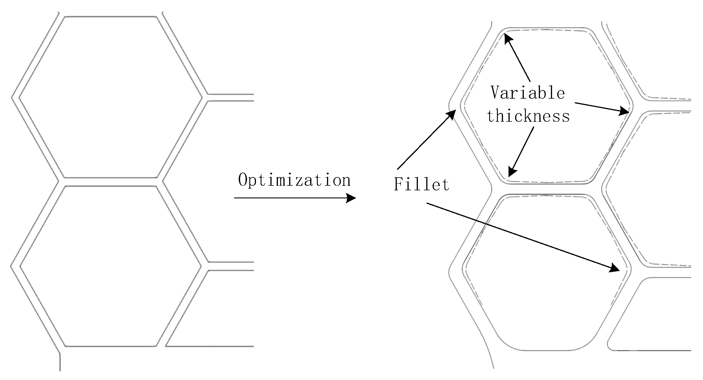
5.1. Optimization of SHD

The SMA honeycomb structure can be represented in a simplified manner as a beam with fixed ends, as illustrated in Figure 13. The graphic also illustrates the distribution of bending moment for this particular beam configuration.
In the study conducted by Aydogdu et al. [28], it was found that beams with varying cross-sectional heights along the length direction exhibit a more uniform strain distribution and a notable reduction in stress concentration. This effect is particularly observed in beams that possess in-plane rotation angles and relative displacement at both ends. The stress distribution along the walls of a shape memory alloy (SMA) honeycomb structure will exhibit uniformity when the wall thickness corresponds to the distribution of bending moments.
Therefore, the thickness of both ends of a non-horizontal cell wall can be estimated as follows:
b = 12 M p t ω E M 3
where b is the minimum wall thickness at the beam’s end, Mp is the bending moment at the beam’s end, and t is the thickness of the honeycomb plate, indicating the beam’s bending curvature. ω is calculated as:
ω = M p E M I
The wall thickness in the middle of the cell wall is calculated using the initial λ. Figure 14 demonstrates the optimization of the SMA honeycomb with variable wall thickness.

5.2. Validation of Optimization

A numerical model of the SHD system was developed using an optimization approach. The strain distribution of this model was then compared to that of the original model in order to assess the efficacy of the optimization scheme. The minimum thickness of the non-horizontal cell wall ends was computed as:
b 1 = 12 M p 1 t ω 1 E M 3 = 12 × 6 × 1.40625 × 10 12 × 0.0019 × 0.5 0.1 × 0.3867 × 0.0225 3 = 0 . 002531   m
Figure 15 shows the optimized numerical model of SHD. R represents the radius of the chamfer angle (unit: mm).
The fracture strain distribution of the optimized model is depicted in Figure 16b. After optimization, there has been a significant reduction in the tension concentration within the specimen. The maximum strain of the optimized model is 6.59% at 10.3% overall strain. The results suggest that the implementation of the honeycomb structure design method resulted in a 1.56-fold increase in the deformation capacity of the SMA materials. Furthermore, the even distribution of cell wall deflection can be attributed to the fillet and variable wall thickness scheme. The stress in the compressed cell walls is greater than the Martensite initial stress of 418 MPa, as shown in Figure 16a. It signifies that the SMA material’s superelastic characteristic is completely utilized in these components. As a result, fatigue fractures in SMA honeycomb can be effectively delayed, thereby preventing the premature failure of SHD. While the fracture strain of SMA plates remains below 6%, the implementation of a honeycomb structure, which leverages the geometrical nonlinearity property, can result in an enlargement of the damper’s macroscopic stain to 10.3%.
In Figure 17, a comparison is made between the responses of the specimen and the optimized SHD during the final axial tension and compression cycle, where the specimen’s response was 10 mm and the SHD’s response was 15 mm per cycle. When subjected to 15 mm of compression or tension, the static residual deformation of the optimized SHD remains below 0.1 mm. Minimum ratios of static residual displacement to maximal displacement are 0.7% or less. In the optimized SHD, the maximum deformation, maximum force, and dissipated energy, which are calculated as the area in a hysteretic loop, are both substantially increased. The specimen experiences a maximum deformation of 10 mm, a maximum force of 2.01 kN, and a dissipation of energy of 1.38 J during the final experimental hysteretic cycle. In the optimized SHD, however, the maximum deformation increased to 15 mm, the maximum force to 14.2 kN, and the dissipated energy to 5.39 J. The maximum force, maximum deformation, and dissipated energy of the optimized SHD are enhanced by 606%, 50%, and 291%, respectively, when compared to the specimen.
When enlarged by a factor of 10, the optimal SHD has a width of around 750 mm, a length of 1700 mm, and a depth of 150 mm. The deformation and force capability will increase to 150 mm and 1420 kN, respectively. Dampers of this magnitude, capable of accommodating large displacements and forces, can be utilized in the construction of simply supported bridges, which are commonly constructed worldwide.

6. Conclusions

In the paper, an innovative SMA honeycomb damper (SHD) is proposed. A prototype of the suggested damper was constructed, experimentally tested, and numerically analyzed. The primary conclusions and recommendations can be stated as follows:
  • The SHD combines the geometrically nonlinear nature of honeycomb structures with the superelastic capabilities of shape memory alloy (SMA) materials. As a result, it has the capability to undergo significant deformation within a limited distance. An SHD of 1700 mm in length possesses a deformation capability of 150 mm, making it suitable for use in typical simply supported bridges.
  • The SHD exhibits exceptional self-centering capacity and stable hysteretic responses. The static residual displacement to maximum displacement ratios are less than 0.7%. The incorporation of this technique in the seismic design of structures has the potential to significantly improve their resilience.
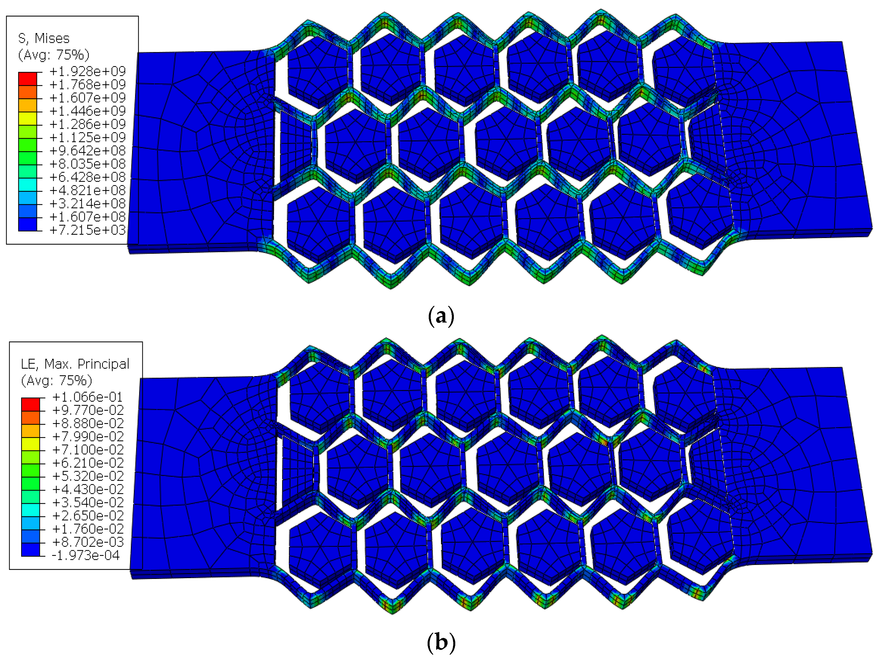
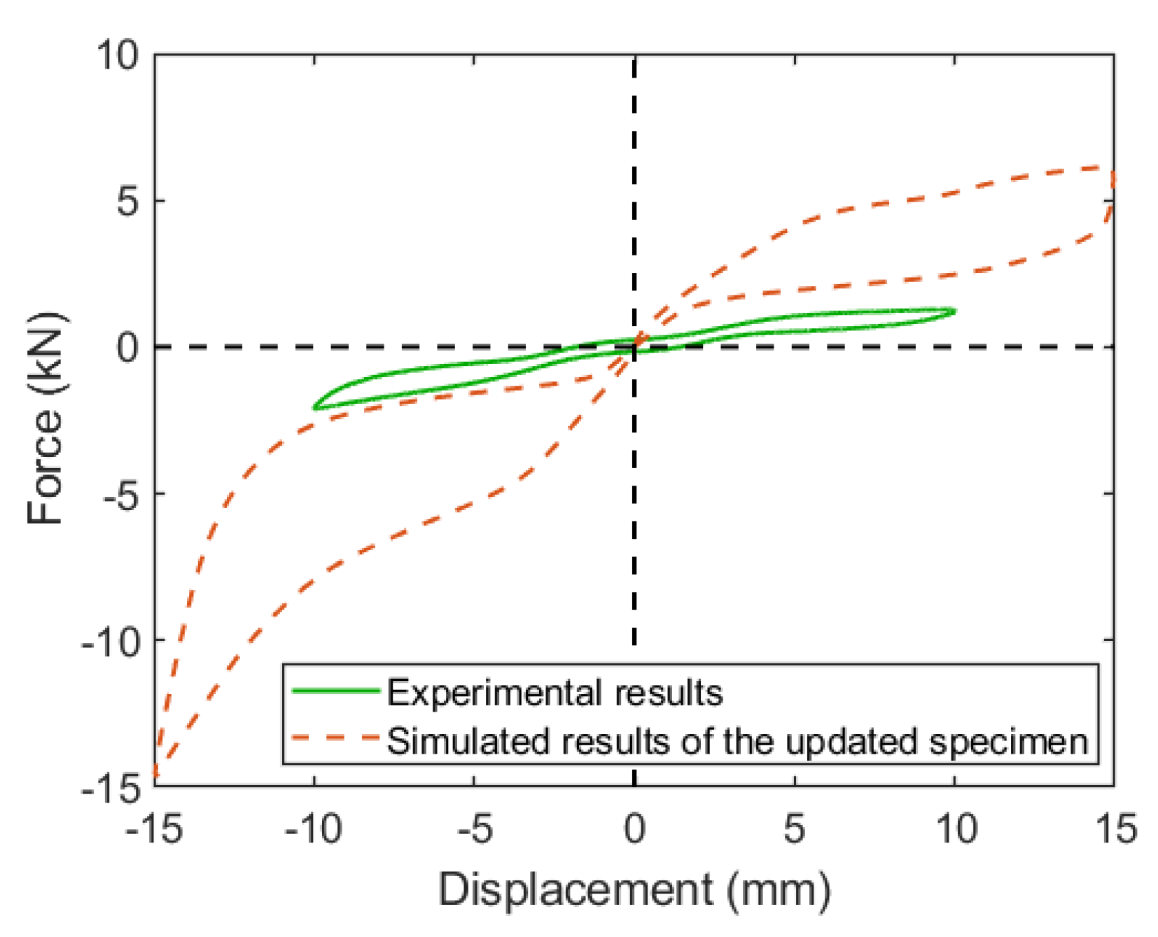
  • The stress and strain concentration that is present at the sharp edges of the SHD can be effectively mitigated by adjusting the thickness of the non-horizontal cell wall. The SHD is capable of supplying over 10.3% of the overall strain, while the local strain remains below the SMA material’s maximal recoverable strain. The honeycomb structure design method increased the deformation capacity of the SMA damper by 60% in the optimized specimen. This enables SHD to exhibit a comparatively larger stroke in comparison to analogous SMA-based devices.
  • A numerical simulation of the application of the SHD in bridges subjected to earthquakes is necessary to verify its effectiveness and applicability in the future.

Author Contributions

Conceptualization, S.C. and G.Z.; methodology, S.C.; software, F.H.; validation, S.C., F.H. and G.Z.; formal analysis, F.H.; investigation, S.C. and F.H.; data curation, F.H. and G.Z.; writing—original draft preparation, S.C. and F.H.; writing—review and editing, G.Z.; visualization, G.Z.; supervision, S.C. and G.Z.; project administration, S.C. and G.Z.; funding acquisition, S.C. and G.Z. All authors have read and agreed to the published version of the manuscript.

Funding

The project was financially supported by the Scientific Research Fund of Institute of Engineering Mechanics, China Earthquake Administration (Grant No. 2019D19), National Natural Science Foundation of China (Grants 52178124, 51978183, 52108445); Natural Science Foundation of Guangdong Province (Grant 2022A1515011250).

Data Availability Statement

The data presented in this study are available on request from the corresponding author. The data are not publicly available due to privacy.

Conflicts of Interest

The authors declare no conflict of interest.

References

  1. Chen, X.; Xiong, J. Seismic resilient design with base isolation device using friction pendulum bearing and viscous damper. Soil Dyn. Earthq. Eng. 2022, 153, 107073. [Google Scholar] [CrossRef]
  2. Xiang, N.; Alam, M.S.; Li, J. Yielding Steel Dampers as Restraining Devices to Control Seismic Sliding of Laminated Rubber Bearings for Highway Bridges: Analytical and Experimental Study. J. Bridge Eng. 2019, 24, 04019103. [Google Scholar] [CrossRef]
  3. Pang, Y.; He, W.; Zhong, J. Risk-based design and optimization of shape memory alloy restrained sliding bearings for highway bridges under near-fault ground motions. Eng. Struct. 2021, 241, 112421. [Google Scholar] [CrossRef]
  4. Cao, S.; Ozbulut, O.E.; Dang, X.; Tan, P. Experimental and numerical investigations on adaptive stiffness double friction pendulum systems for seismic protection of bridges. Soil Dyn. Earthq. Eng. 2024, 176, 108302. [Google Scholar] [CrossRef]
  5. Alam, M.S.; Bhuiyan, M.R.; Billah, A.M. Seismic fragility assessment of SMA-bar restrained multi-span continuous highway bridge isolated by different laminated rubber bearings in medium to strong seismic risk zones. Bull. Earthq. Eng. 2012, 10, 1885–1909. [Google Scholar] [CrossRef]
  6. Andreacola, F.R.; Brando, G. Optimization methods for the design of advanced 3d-printed metal seismic dissipation devices. ce/papers 2023, 6, 888–892. [Google Scholar] [CrossRef]
  7. De Domenico, D.; Tubaldi, E.; Takewaki, I.; Karavasilis, T.; Dall’Asta, A.; Lavan, O. Editorial: Recent Advances and Applications of Seismic Isolation and Energy Dissipation Devices. Front. Built Environ. 2020, 6, 126. [Google Scholar] [CrossRef]
  8. Brando, G.; D’Agostino, F.; De Matteis, G. Seismic performance of MR frames protected by viscous or hysteretic dampers. Struct. Des. Tall Spec. Build. 2015, 24, 653–671. [Google Scholar] [CrossRef]
  9. De Matteis, G.; D’Agostino, F.; Brando, G. Experimental tests on steel buckling inhibited shear panels. Open Constr. Build. Technol. J. 2014, 8, 279–288. [Google Scholar] [CrossRef]
  10. Michailidis, P.A.; Triantafyllidis, N.; Shaw, J.A.; Grummon, D.S. Superelasticity and Stability of a Shape Memory Alloy Hexagonal Honeycomb under In-plane Compression. Int. J. Solids Struct. 2009, 46, 2724–2738. [Google Scholar] [CrossRef]
  11. Galehdari, S.; Khodarahmi, H. Design and analysis of a graded honeycomb shock absorber for a helicopter seat during a crash condition. Int. J. Crashworthiness 2016, 21, 231–241. [Google Scholar] [CrossRef]
  12. Lee, M.; Lee, J.; Kim, J. Seismic Retrofit of Structures Using Steel Honeycomb Dampers. Int. J. Steel Struct. 2017, 17, 215–229. [Google Scholar] [CrossRef]
  13. Javanmardi, A.; Ghaedi, K.; Ibrahim, Z.; Huang, F.; Xu, P. Development of a new hexagonal honeycomb steel damper. Arch. Civ. Mech. Eng. 2020, 20, 63. [Google Scholar] [CrossRef]
  14. Hedayati Dezfuli, F.; Alam, M.S. Smart lead rubber bearings equipped with ferrous shape memory alloy wires for seismically isolating highway bridges. J. Earthq. Eng. 2018, 22, 1042–1067. [Google Scholar] [CrossRef]
  15. Ozbulut, O.E.; Hurlebaus, S. Seismic assessment of bridge structures isolated by a shape memory alloy/rubber-based isolation system. Smart Mater. Struct. 2010, 20, 015003. [Google Scholar] [CrossRef]
  16. Shrestha, B.; He, L.-X.; Hao, H.; Bi, K.; Ren, W.-X. Experimental study on relative displacement responses of bridge frames subjected to spatially varying ground motion and its mitigation using superelastic SMA restrainers. Soil Dyn. Earthq. Eng. 2018, 109, 76–88. [Google Scholar] [CrossRef]
  17. Zheng, Y.; Dong, Y. Performance-based assessment of bridges with steel-SMA reinforced piers in a life-cycle context by numerical approach. Bull. Earthq. Eng. 2019, 17, 1667–1688. [Google Scholar] [CrossRef]
  18. Zheng, Y.; Dong, Y.; Li, Y. Resilience and life-cycle performance of smart bridges with shape memory alloy (SMA)-cable-based bearings. Constr. Build. Mater. 2018, 158, 389–400. [Google Scholar] [CrossRef]
  19. Cao, S.; Ozbulut, O.E. Long-stroke shape memory alloy restrainers for seismic protection of bridges. Smart Mater. Struct. 2020, 29, 115005. [Google Scholar] [CrossRef]
  20. Li, S.; Hedayati Dezfuli, F.; Wang, J.-Q.; Shahria Alam, M. Seismic vulnerability and loss assessment of an isolated simply-supported highway bridge retrofitted with optimized superelastic shape memory alloy cable restrainers. Bull. Earthq. Eng. 2020, 18, 3285–3316. [Google Scholar] [CrossRef]
  21. Cardone, D.; Sofia, S. Numerical and Experimental Studies on the Seismic Retrofit of Simply Supported Bridges Using Superelastic Restrainers. Adv. Mater. Res. 2012, 446–449, 3291–3294. [Google Scholar] [CrossRef]
  22. Guo, A.; Zhao, Q.; Li, H. Experimental study of a highway bridge with shape memory alloy restrainers focusing on the mitigation of unseating and pounding. Earthq. Eng. Eng. Vib. 2012, 11, 195–204. [Google Scholar] [CrossRef]
  23. Fang, C.; Zheng, Y.; Chen, J.; Yam, M.C.; Wang, W. Superelastic NiTi SMA cables: Thermal-mechanical behavior, hysteretic modelling and seismic application. Eng. Struct. 2019, 183, 533–549. [Google Scholar] [CrossRef]
  24. Qiu, C.; Fang, C.; Liang, D.; Du, X.; Yam, M.C. Behavior and application of self-centering dampers equipped with buckling-restrained SMA bars. Smart Mater. Struct. 2020, 29, 035009. [Google Scholar] [CrossRef]
  25. Fang, C.; Qiu, C.X.; Wang, W.; Alam, M.S. Self-Centering Structures Against Earthquakes: A Critical Review. J. Earthq. Eng. 2023, 27, 4354–4389. [Google Scholar] [CrossRef]
  26. Ge, J.; Saiidi, M.S.; Varela, S. Computational studies on the seismic response of the State Route 99 bridge in Seattle with SMA/ECC plastic hinges. Front. Struct. Civ. Eng. 2019, 13, 149–164. [Google Scholar] [CrossRef]
  27. Wang, J.-Q.; Li, S.; Dezfuli, F.H.; Alam, M.S. Sensitivity analysis and multi-criteria optimization of SMA cable restrainers for longitudinal seismic protection of isolated simply supported highway bridges. Eng. Struct. 2019, 189, 509–522. [Google Scholar] [CrossRef]
  28. Zheng, W.-Z.; Wang, H.; Li, J.; Shen, H.-J. Parametric study of SMA-based friction pendulum system for response control of bridges under near-fault ground motions. J. Earthq. Eng. 2021, 25, 1494–1512. [Google Scholar] [CrossRef]
  29. Deng, J.D.; Hu, F.L.; Ozbulut, O.E.; Cao, S.S. Verification of multi-level SMA/lead rubber bearing isolation system for seismic protection of bridges. Soil Dyn. Earthq. Eng. 2022, 161, 107380. [Google Scholar] [CrossRef]
  30. Zheng, W.; Tan, P.; Li, J.; Wang, H.; Tan, J.; Sun, Z. Sliding-LRB incorporating superelastic SMA for seismic protection of bridges under near-fault earthquakes: A comparative study. Soil Dyn. Earthq. Eng. 2022, 155, 107161. [Google Scholar] [CrossRef]
  31. Vaiana, N.; Capuano, R.; Rosati, L. Evaluation of path-dependent work and internal energy change for hysteretic mechanical systems. Mech. Syst. Signal Process. 2023, 186, 109862. [Google Scholar] [CrossRef]
  32. Cao, S.; Ozbulut, O.E.; Wu, S.; Sun, Z.; Deng, J. Multi-level SMA/lead rubber bearing isolation system for seismic protection of bridges. Smart Mater. Struct. 2020, 29, 055045. [Google Scholar] [CrossRef]
  33. Zheng, W.; Wang, H.; Li, J.; Shen, H. Performance evaluation of bridges isolated with SMA-based friction pendulum system at low temperatures. Soil Dyn. Earthq. Eng. 2019, 125, 105734. [Google Scholar] [CrossRef]
  34. Li, S.; Wang, J.; Alam, M.S. Seismic performance assessment of a multispan continuous isolated highway bridge with superelastic shape memory alloy reinforced piers and restraining devices. Earthq. Eng. Struct. Dyn. 2021, 50, 673–691. [Google Scholar] [CrossRef]
  35. Yang, T.; Li, T.; Tobber, L.; Pan, X. Experimental and numerical study of honeycomb structural fuses. Eng. Struct. 2020, 204, 109814. [Google Scholar] [CrossRef]
  36. Zhakatayev, A.; Kappassov, Z. Analytical modeling and design of negative stiffness honeycombs. Smart Mater. Struct. 2020, 29, 045024. [Google Scholar] [CrossRef]
  37. Marmo, F.; Sessa, S.; Vaiana, N.; De Gregorio, D.; Rosati, L. Complete solutions of three-dimensional problems in transversely isotropic media. Contin. Mech. Thermodyn. 2020, 32, 775–802. [Google Scholar] [CrossRef]
  38. Wang, W.; Fang, C.; Liu, J. Large size superelastic SMA bars: Heat treatment strategy, mechanical property and seismic application. Smart Mater. Struct. 2016, 25, 075001. [Google Scholar] [CrossRef]
  39. Dassault Systemes. ABAQUS 2017 Documentation. English Version. 2018. Available online: http://130.149.89.49:2080/v6.14/ (accessed on 7 November 2023).
  40. Vaiana, N.; Rosati, L. Analytical and differential reformulations of the Vaiana–Rosati model for complex rate-independent mechanical hysteresis phenomena. Mech. Syst. Sig. Process. 2023, 199, 110448. [Google Scholar] [CrossRef]
Figure 1. A honeycomb.
Applsci 13 13154 g001
Figure 2. Superelastic SMA honeycomb damper: (a) overview and (b) side view.
Applsci 13 13154 g002
Figure 3. The working mechanism of superelastic SMA honeycomb damper.
Applsci 13 13154 g003
Figure 4. Honeycomb beam in local coordinate system.
Applsci 13 13154 g004
Figure 5. The specimen: (a) dimensions of the SMA honeycomb, (b) installment of the SMA honeycomb, (c) lubricating oil applied, and (d) installment of the two stainless-steel plates.
Applsci 13 13154 g005
Figure 6. The test setup: (a) the frame and (b) the clamping of SHD.
Applsci 13 13154 g006
Figure 7. Experimental response of the specimen at different loading amplitudes.
Applsci 13 13154 g007
Figure 8. Variation in mechanical properties of the specimen with increasing displacement loading: (a) maximum forces; (b) secant stiffness; (c) dissipated energy; and (d) equivalent viscous damping ratio.
Applsci 13 13154 g008
Figure 9. Fracture of the specimen.
Applsci 13 13154 g009
Figure 10. Finite element model of SHD: (a) SMA honeycomb; (b) steel plates; and (c) FE model of SHD.
Applsci 13 13154 g010
Figure 11. Comparison and experimental and simulated responses of the specimen.
Applsci 13 13154 g011
Figure 12. Responses of the SHD numerical model: (a) stress distribution and (b) strain distribution.
Applsci 13 13154 g012
Figure 13. Bending moment distribution of non-horizontal cell wall.
Applsci 13 13154 g013
Figure 14. Optimization of SMA honeycomb.
Applsci 13 13154 g014
Figure 15. Optimized numerical model of SHD.
Applsci 13 13154 g015
Figure 16. Responses of the optimized SHD numerical model: (a) stress distribution and (b) strain distribution.
Applsci 13 13154 g016
Figure 17. Comparison of the responses of the experimental results of the specimen and the optimized SHD.
Applsci 13 13154 g017
Disclaimer/Publisher’s Note: The statements, opinions and data contained in all publications are solely those of the individual author(s) and contributor(s) and not of MDPI and/or the editor(s). MDPI and/or the editor(s) disclaim responsibility for any injury to people or property resulting from any ideas, methods, instructions or products referred to in the content.

