1. Introduction
Despite the commonly used techniques for surgical treatment of vertebral compression fractures in the thoracic or lumbar spine, the selection of the appropriate type of fixation is still open to debate. Prior experimental research conducted by the authors has demonstrated that employing long-segment fixation (LSF) in the design of a posterior spinal fixation system (PFS) yields superior outcomes compared to short-segment fixation (SSF) [
1]. It was observed that a PFS design with a short-segment configuration does not offer sufficient stability, particularly during flexion–extension movements. Such a PFS design may lack the necessary rigidity, resulting in an excessive range of motion at the thoracolumbar junction [
1]. In line with these findings, McDonnell et al. [
2] and Bolesta et al. [
3] reported immediate stabilization of the affected segment when implementing LSF, along with achieving higher stiffness values compared to those seen in physiological systems. These results align with the observations conducted by Disch et al. [
4], who demonstrated that a four-segment fixation is stiffer in comparison to a two-segment fixation.
Compression fractures can often contribute to increased thoracic kyphosis, leading to disorders of the physiological curvature of the spine and thus causing spinal imbalance [
5,
6]. Conversely, pre-existing alterations in spinal curvature may influence how forces are distributed, potentially predisposing to the occurrence of fractures. According to the studies by Kado et al., it is imperative to acknowledge the complexity of the interaction between fractures and thoracic kyphosis, which likely operates bidirectionally [
7]. Based on clinical practice, it was noted that surgical treatment of fractures allows for shorter hospitalization time, better correction of deformities in the region of the thoracic kyphosis, and the possibility of direct decompression of the spinal canal [
8]. Furthermore, in order to achieve good clinical outcomes of treatment, it is crucial to reduce kyphosis and restore the correct sagittal alignment of the spine, which can be ensured by LSF [
9]. Through an assessment of the correlation between thoracic kyphosis angle and clinical outcomes of treatment burst fractures of the thoracolumbar spine, Tisot et al. [
10] observed that patients treated conservatively had greater deformities of the spinal curvature than patients treated surgically. Yaman et al. [
11] systematically reviewed the literature spanning the years 2010–2020, focusing on investigations related to thoracolumbar fractures and kyphosis. Their findings indicated that unstable burst fractures represent a predominant etiological factor in the development of posttraumatic kyphosis. Consequently, it is advised that surgical intervention employing a PFS efficacy in effecting kyphosis correction is concomitant with diminished blood loss and mitigated complication rates.
According to AO Foundation Surgery Reference, in the case of long-segment designs, the application of transverse connectors is a classic fixation technique that is used to improve the stability of the damaged spinal segment. The most popular PFS configurations use two connectors, resulting in the frame structure of the PFS. However, these types of systems are increasingly being replaced by a single transverse connector, as this significantly reduces the operation time. At the same time, there are ongoing discussions on the advisability of using transverse connectors in PFS designs. Present clinical standards are moving towards percutaneous minimally invasive surgery, which primarily protects the functional spinal units (spinal motion segments), thus significantly shortening the procedure and saving the materials used [
9,
12,
13]. In contrast, the use of transverse connectors in a PFS design is associated with more invasive open surgery, during which the patient must be opened to insert implants, which is obviously associated with a longer operation time, major tissue disruption, and longer hospitalization.
Therefore, the aim of this study was to determine the impact of using transverse connectors in PFS designs in the case of a vertebral compression fracture on selected mechanical parameters of the thoracolumbar spine under conditions of instability. The research goal was realized by conducting experimental tests and numerical simulations.
2. Materials and Methods
2.1. Experimental Study
Experimental investigations were performed using specimens sourced from eight domestic swine, aged between 6 and 10 months and weighing between 90 and 110 kg. Isolated specimens of the thoracolumbar spine (Th7–L5) were meticulously prepared by removing the surrounding soft tissues while retaining the intact intervertebral discs (IVDs), ligaments, articular joints, and, to some extent, ribs and muscles.
To evaluate the influence of transverse connectors in posterior spinal fixation system designs on selected mechanical parameters, five distinct experimental groups underwent testing (
Figure 1). First, the physiological specimen (P) was subjected to testing. Subsequently, a compression fracture of the Th12 vertebra (F) was simulated in the physiological specimens by making a precise incision in the vertebral body. This incision was designed to mimic the formation and morphology of such a fracture, representing a type A fracture, which is statistically the most common in the thoracolumbar junction [
14,
15,
16]. Following the creation of the compression fracture, transpedicular fixation was performed in each of the affected thoracolumbar segments using three different configurations: four-segment fixation without transverse connectors (long-segment posterior fixation system, LSF4—2 levels above and 2 levels below the compression fracture), four-segment fixation with one transverse connector (LSF4 TC1), and four-segment fixation with two transverse connectors (LSF4 TC2).
The experiment utilized the SOCORE transpedicular fixation system manufactured by NovaSpine (Domasław, Poland). For the vertebral bodies of the thoracic spine, polyaxial screws with a diameter of 5 mm and a length of 35 mm were implanted, while for the vertebral bodies of the lumbar spine, screws with a diameter of 6 mm and a length of 40 mm were used. These pedicle screws were then connected with 5.5 mm diameter rods. Transverse connectors, measuring 55 mm in length, were employed. To confirm the correct implantation of pedicle screws in the vertebral bodies (Th10, Th11, L1, and L2), each specimen of the thoracolumbar spine underwent diagnostic X-ray imaging in both sagittal and coronal planes.
The experimental tests were conducted in a manner similar to the test procedure presented in a previous study that analyzed the impact of the length of fixated segments on the damaged thoracolumbar spine [
1]. Loading was performed using an MTS 858 Mini Bionix testing machine (MTS Systems, Eden Prairie, MN, USA), and the specimens were subjected to forces simulating typical activities of daily life. The prepared specimens were secured in a specially designed test rig equipped with upper and lower grips, where the vertebral bodies Th7 and L5 were clamped using eight cylindrically arranged screws.
An analysis of all considered configurations was carried out for loading conditions simulating flexion. Previous experimental research [
1] demonstrated that compression did not significantly affect spinal stability. It was noted that spinal stability is influenced by both flexion and extension. However, during extension, the primary load is transmitted through articular processes, resulting in a lesser impact of vertebral fractures on load transmission in the examined spinal segment. Flexion represents the most complex loading scenario among the types analyzed, as it involves the greatest range of motion in the sagittal plane. Therefore, the experiment was conducted with a load-simulating flexion in the angular range of 0° to 4° [
17].
Each study group was subjected to 20 load cycles at a frequency of 1 Hz, corresponding to the frequency of human gait. It was also assumed that the first 4 cycles served as conditioning cycles due to the hyperelastic properties of soft tissues such as intervertebral discs (IVDs) and ligaments, requiring preloading to stabilize the test system. Based on the conducted experimental tests, mechanical parameters were determined, including the bending stiffness coefficient (for the 20th load cycle) and the dissipation energy, which serves as a measure of the damping ratio of the test systems.
Statistical Analysis
All the results obtained from the experimental testing were subjected to statistical analysis using Statistica 13.1 software developed by StatSoft Inc. in Tulsa, OK, USA. The results were presented in the form of means along with their corresponding standard deviations. The mechanical parameters were analyzed employing the Kruskal–Wallis non-parametric test, followed by Dunn’s multiple comparison post hoc test.
The Kruskal–Wallis test serves as a non-parametric alternative to the one-way analysis of variance, allowing for the comparison of the distributions of more than two independent groups, each containing at least three data points. Dunn’s test, on the other hand, is a post hoc pairwise test designed for making multiple comparisons of mean rank sums. The statistical analyses were conducted with a significance level set at p < 0.05, indicating that results were considered statistically significant if the probability of their occurrence by chance was less than 5%.
2.2. Digital Image Correlation
In addition, changes in the distribution of displacements and strains of load-bearing rods were analyzed depending on the number of connectors used. The assessment of the changes occurring on the load-bearing implant components was performed using the Digital 3D Image Correlation System Q-400 (Dantec Dynamics, Skovlunde, Denmark). Digital Image Correlation (DIC) allowed us to measure the surface deformities of the examined implants during loading, simulating flexion. A distinctive and unique speckle pattern was applied to the surfaces of the implants by spraying them with white and black paint. In the case of the measurements taken, the system included two digital cameras and a lighting set-up dedicated to the Dantec Dynamics Q-400 DIC measurement system. The cameras were calibrated using the High-Precision Glass Target calibration plate (40 mm object size).
In order to determine the validity of using transverse connectors in a long-segment PFS design, two configurations were selected for DIC analysis. In light of the ongoing debate on the advisability of using transverse connectors in PFS designs, the configuration without transverse connectors was compared to the configuration with two transverse connectors, as the latter is more often used in clinical practice and results in the frame structure of the PFS. The analysis covered the rod area at the level of the Th12 vertebral body fracture.
2.3. Numerical Simulation
2.3.1. Development of FE Models
A three-dimensional (3D) geometric model of the thoracolumbar spine (Th7–L3) was built based on the spinal dimensions derived from the analysis of computed tomography (CT) images following the methodology presented in Szkoda et al. [
18] and Szkoda-Poliszuk et al. [
19]. Based on the model obtained in the InVesalius 3.1.1 software, the geometric dimensions of nine vertebrae (Th7–L3) were obtained, which corresponded to the number of segments adopted in experimental tests. The values of each parametric dimension of the vertebrae included in the numerical model were confirmed against the vertebral dimensions reported in the literature [
20,
21]. In addition, based on the model obtained from CT imaging, the position and inclination angle of individual vertebrae were measured in relation to the long axis of the spine in order to represent the geometry of the thoracolumbar spine.
The geometric model of the thoracolumbar spine (Th7–L3) was created using the ANSYS Mechanical APDL 18.2 software. In addition to the vertebrae, the model also recreated the geometry of the IVDs, endplates, and ligament systems. In order to reduce excessive mobility of the thoracolumbar junction, a simplified muscular system was also recreated, which was modeled at the level of the Th8-Th9 and Th12-L1 motion segments (
Figure 2A). The endplate thickness was modeled as 10% of the vertebral body height [
22]. The model took into account the detailed structure of the IVD. Not only was differentiation assumed between the nucleus pulposus area and the annulus fibrosus, but also differences between the outer, medium, and inner layers of the annulus fibrosus itself (by differentiating their mechanical parameters). The geometry of the SOCORE transpedicular fixation system by NovaSpine was modeled to analyze the impact of using transverse connectors in PFS designs, and this system was also used during experimental tests. In order to optimize the running time of the numerical simulations, the screw geometry was simplified by omitting threads.
Numerical simulations were carried out for four cases, similar to experimental tests (
Figure 2). LSF4 TC1 was omitted as it was shown from experimental tests that the results did not have a significant impact compared to the other study groups.
In the discrete model, the vertebrae and intervertebral discs were represented using SOLID187 10-node tetrahedral solid elements. Each vertebral body was characterized as cancellous bone encased in a layer of cortical bone with a thickness ranging from 0.5 to 1 mm [
23]. Additionally, the presence of superior and inferior endplates was considered in all vertebrae. The elements used to describe the transpedicular fixation components, such as screws, rods, and transverse connectors, were also SOLID187 solid elements.
Within the annulus fibrosus matrix of the IVD, three cylindrical layers of collagen fibers were modeled using SHELL181 four-node shell elements, each having six degrees of freedom at every node. These fibers within the individual layers of the IVD were inclined at a 30° angle and oriented alternately to the right and left [
24].
Furthermore, all four major types of ligaments typically found in the spine—namely, the anterior longitudinal ligament (ALL), posterior longitudinal ligament (PLL), intertransverse ligament (ITL), and interspinous ligament (ISL)—were also represented using SHELL181 four-node shell elements in the model. As for the muscles, they were simulated using LINK180 two-node elements, with each node having three degrees of freedom.
2.3.2. Material Properties
Vertebral bone tissue and endplates were described by isotropic, linear-elastic material properties (
Table 1). The IVD was designed in alignment with the vertebral model proposed by Schmidt et al. [
25], who modeled the structure of the annulus fibrosus as a matrix strengthened with layers of collagen fibers. The nucleus pulposus, together with the annulus fibrosus matrix, were described by nonlinear material properties using the Mooney-Rivlin hyperelastic model. The fiber layers were assigned isotropic, nonlinear material properties. In contrast, ligaments (ALL, PLL, ISL, and ITL) and muscles were described by isotropic, linear-elastic material properties. At the same time, surface-to-surface contact elements (with a friction coefficient of 0.1) were introduced on the articular facets. The PFS design (screws, rods, and transverse connectors) was described by isotropic, linear-elastic material properties.
2.3.3. Boundary and Loading Conditions
For all configurations of the thoracolumbar spine model, numerical simulations were conducted by applying a moment of force of 7 Nm [
17], similar to experimental tests. The load was applied to the superior endplate of the Th7 vertebral body. In each case, the models were fixed by eliminating all degrees of freedom from the nodes on the inferior endplate of the L3 vertebral body and in the muscle nodes.
Numerical simulations were employed to calculate such parameters as the angular range of motion of individual motion segments, intradiscal pressure in individual IVDs, and stress distribution on articular facets. The range of angular motion for individual segments of the thoracolumbar junction was defined as angular displacement.
2.3.4. Validation of Numerical Model
The validation process was aimed at checking the degree of compliance of the adopted assumptions of the numerical model representing the biomechanics of the thoracolumbar spine with the real experimental conditions. As there are few studies on the thoracolumbar spine in the available literature, validation was carried out for the lumbar spine (L1–L5). Three cases of loading action were analyzed: compression (for the forces of 300 N and 500 N), flexion, and extension (for the moments of a force of 2.5 Nm, 5.0 Nm, and 7.5 Nm). In each case, the load was applied to the superior endplate of the L1 vertebral body. In addition, the models were fixed by eliminating all degrees of freedom of the nodes on the inferior endplate of the L5 vertebral body.
The obtained results were compared with the experimental and numerical results presented in the literature by Xu et al. [
17] and Panjabi et al. [
35]. The parameter selected for validation was the angular range of motion of individual segments (
Figure 3). Based on the conducted validation, it was noted that the obtained results were similar to those obtained by the authors of other experimental and numerical research studies. Therefore, the validity of the adopted assumptions regarding both the representation of the spine geometry and the material properties was confirmed.
3. Results
3.1. Validation of the Numerical Model against the Experimental Results for the Physiological System
The results were validated to compare the prepared finite element method solution with the data obtained during experimental tests. Validation of the model against the experimental data was performed for a compressive load of 650 N. The results obtained for the physiological numerical model of the spine were compared with the results obtained for the same system analyzed during the experiment. The validation process was aimed at checking the degree of compliance of the adopted assumptions of the numerical model representing the biomechanics of the thoracolumbar junction with the in vitro behavior of that region. Based on the conducted validation, it was noted that the maximum displacement values (read along the long axis of the spine) obtained during the experiment averaged 2.68 ± 0.32 mm and were comparable to the values obtained for numerical simulations, where this value was equal to 3.16 mm.
3.2. Bending Stiffness Coefficient (kM) and Dissipation Energy (∆E)
The bending stiffness coefficient obtained for specimens with a fracture was approximately 28% lower than the value obtained for the physiological system. The introduction of LSF4 resulted in a significant increase in the stiffness coefficient by approximately 49% compared to the values observed for P. When connecting the rods with transverse connectors in the four-segment fixation, there was an increase in the coefficient compared to four-segment fixation without connectors. In the case of configurations LSF4 TC1 as well as LSF4 C2, the average increase ranged from 2 to 4 Nm/rad (
Figure 4). Furthermore, it was demonstrated that statistically significant differences existed between the values obtained for F and LSF4 TC1 (
p = 0.03).
The mean damping energy of the examined physiological spine specimens was nearly identical to the value obtained for the specimens with a fracture (
Table 2). Similar values of dissipation energy were also achieved for all three configurations of four-segment fixation. No statistically significant differences were found among the analyzed study groups.
3.3. Digital Image Correlation—Distribution of Displacement and Strain
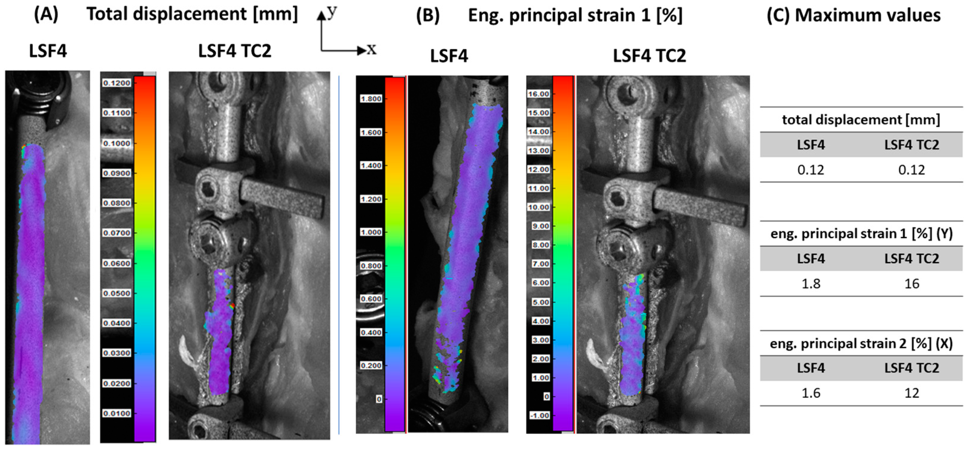
An analysis using digital image correlation showed that in the case of LSF4, the maximum value of total rod displacement in the analyzed area did not exceed 0.12 mm (at the level of the Th12 vertebral body fracture). This value was comparable to the value obtained in the case of LSF4 TC2 (
Figure 5A). When considering the distribution of principal strains determined from recorded displacements, it was noted that higher values were obtained for LSF4 TC2, both in the case of strains in the longitudinal direction of the bar (
y-axis—ε1) and in the transverse direction (
x-axis—ε2) (
Figure 5B).
3.4. Range of Motion
An analysis of the obtained values of the angular range of motion in the thoracolumbar spine showed that in the case of P, the highest mobility value was obtained for the Th7–Th8 segment (to which a load-simulating flexion was directly applied) and for the Th12–L1 segment (in which the thoracic spine transitions to lumbar spine). It was noted that a fracture of the Th12 vertebra disrupted the transmission of loads through the spinal column, which may be a contributing factor to spinal instability. In the case of F, increased mobility values were observed across all segments. The obtained values were, on average, approximately 25% higher than those obtained for the P (
Figure 6A). A significant increase in mobility was also observed for the Th10–Th11 segment, located above the fracture, where the obtained value was approximately 42% higher than the value of the physiological system.
When using LSF4 TC2, the mobility of the Th8–Th9 and Th9–Th10 segments was approximately 7% higher, and for the Th10–Th11 and Th11–Th12 segments, it was approximately 27% higher than the values obtained for the same segments in the case of P. For the other segments, the obtained mobility values were lower in the physiological case. It was also shown that the introduction of LSF4 TC2 caused an increase in mobility in almost all segments of the thoracolumbar junction by an average of approximately 15% compared to the values obtained for the LSF4 fixation without connectors. In the case of the Th12–L1 segment, the mobility value decreased by approximately 32% compared to the value obtained for fixation without transverse connectors.
3.5. Intradiscal Pressure
Based on the results of the intradiscal pressure of the IVDs, it was observed that a fracture of the Th12 vertebra resulted in an increase in the pressure value by an average of approximately 12% compared to the values received for the physiological configuration (
Figure 6B). In both cases, it was also noted that the pressure values were higher in the thoracic segment than in the lumbar segment, and the highest value was obtained in the Th7–Th8 segment.
In the case of LSF4 TC2, it was noted that the values were, on average, approximately 50% higher than in the P case. The highest values were also obtained in the segments of the thoracic spine, while the pressure values of the IVDs in the lumbar spine were lower. Additionally, the highest value was obtained in the Th7–Th8 segment, as in the physiological model. It was also observed that the introduction of LSF4 TC2 increased the pressure in all IVDs by approximately 10% compared to the values obtained for LSF4.
3.6. Stress on the Articular Facets
An analysis of stress distribution according to the von Mises hypothesis on articular facets showed that the highest values for P were obtained in the region of the Th12 vertebra. This may be influenced by a change in the orientation of articular facets in the Th11–Th12 and Th12–L1 segments, as well as a change in the spinal curvature. In the case of F, it was noted that the stress value in the area of these segments increased as compared to the case of P. For the other segments of the thoracolumbar spine, the stress values were the same in both analyzed cases (
Figure 6C).
In addition, the analysis showed that in the case of LSF4 TC2, the highest stresses were obtained for the L2–L3 segment, i.e., the segment below the fixated spinal region. The stresses were comparable to the values obtained in the case of LSF4. For the other segments of the thoracolumbar spine, the stress values were the same in both analyzed cases.
4. Discussion
The performed analysis of the impact of using transverse connectors in PFS designs made it possible to assess the mechanical parameters of the thoracolumbar spine under conditions of its instability (in the case of a compression fracture of a single vertebra). The obtained results can be used in clinical studies associated with the introduction of novel implant solutions for the stabilization of thoracolumbar spine injuries and the feasibility of minimally invasive surgery as an alternative to open surgery.
The tests carried out showed that the introduction of transverse elements in a PFS design results in a slight increase in stiffness compared to fixation without connectors. A similar relationship was observed in experimental research by Kuklo et al. [
36], who assessed the biomechanical properties (range of motion and stability) of LSF used in the thoracic spine (Th4–Th10). The researchers showed that transverse connectors do not increase stability during flexion, extension, or lateral bending. However, they observed that both one transverse connector (regardless of location) and two transverse connectors improve stability during axial rotation of such a long fixated spinal segment. Also, Shaw et al. [
37] showed that the use of transverse connectors (one or two) in the cervical spine should be reserved only for unstable injuries involving the posterior column of the spine and laminectomy procedures because they increase the stiffness of the fixated cervical spine (C2–T1), especially during axial rotation.
Numerous in vitro experimental studies indicate that the insertion of implants changes the system of load transmission through the spinal structures. The literature shows that lumbar spine mobility increases above and below the fixated area, especially in the segments directly adjacent to the implantation region [
38,
39,
40]. Similar relationships were observed by Bastian et al. [
41], who conducted in vitro experiments assessing the mobility of segments adjacent to the damaged thoracolumbar spine, within which transpedicular fixation was inserted. Their biomechanical and radiological tests showed that in the segments adjacent to the fixated segments, there is increased mobility as well as increased pressure within the IVDs. However, it is uncertain whether the increase in these parameters can lead to degenerative changes in the structures of adjacent segments. Bastian et al. [
41] also showed that during the transmission of loads through the implant-stabilized lumbar spine (Th12–L2), the mobility of the Th11–Th12 segment, located above the fixated region, increases significantly.
The authors of the present study observed that the introduction of transverse connectors in a PFS design results in a slight increase in mobility and pressure in the IVD (statistically insignificant differences) compared to fixation without connectors. This result indicates that transverse connectors in such configurations do not bring about a visible change in the overall fixation of the damaged spine, as is often assumed. In addition, it was noted that the choice of LSF may result in excessive stiffness of the considered spinal region below the fracture site, as evidenced by the limited mobility of the last three segments in the analyzed spinal region compared to the physiological system. It was also shown that the use of LSF significantly increases the pressure in intervertebral disks above the fixation site, which may lead to the development of degenerative changes in these elements.
It should be remembered that excessive stiffness of the evaluated spinal area may consequently lead to increased mobility of the segments immediately adjacent to the implantation region. This elevated mobility may subsequently increase the curvature of the thoracic kyphosis, potentially leading to issues like pedicle screw breakage or loosening [
38,
40]. It, therefore, appears that LSF with the use of transverse connectors may be justified primarily in the treatment of spinal deformities, such as scoliosis. In this case, however, the use of a single connector is pointless because it does not create a stable mechanical construct in the form of a complete frame structure, as is the case with the use of two connectors. Considering the huge forces counteracting the correction of the spine during its fixation with the use of implants (caused by, among other factors, the tension of the muscular system), the use of a frame structure can have a significant impact on maintaining the effects of correction until the spinal column is fully fused. On the other hand, the use of transverse connectors in the fixation of spinal fractures is not fully justified.
Based on the conducted research using digital image correlation and numerical simulation, it was noted that total displacements obtained on the rods are comparable between two configurations—without transverse connectors and with two connectors. This result indicates that while the use of one connector may, in justified cases, affect the fixation effect, the use of two connectors is not justified and may only contribute to the prolongation of the surgical procedure. The observed values of strain on the rod surfaces are higher when using transverse connectors (LSF4 TC1 and LSF4 TC2) than in four-segment fixation without connectors (LSF4). Such changes in the strain state are justified due to the appearance of additional rigid attachment points changing the load transfer system. It was also shown that the distribution of stresses and strains reduced according to the Huber–von Mises hypothesis and obtained on the rods for both configurations (LSF4 and LSF4 TC2) are practically the same, which again indicates that there is no justification for the use of transverse connectors, especially in the frame structure (two connectors). In addition, the obtained maximum stress values are within the strength limits of the rod material [
42].
Based on the conducted research, preliminary conclusions can be drawn that the use of transverse connectors is not necessary in a PFS design in the case of surgical treatment of a vertebral compression fracture. The rods are joined with transverse elements towards the end of a several-hour-long, complicated open surgery, which further prolongs the operation time. The elimination of transverse elements may contribute to a shorter procedure time or a less invasive and percutaneous procedure (minimally invasive surgery). In addition, the insertion of transverse connectors is often associated with damage to the spinous processes and interspinous ligaments, depending on the place where they must be inserted. Due to the fact that the posterior spinal column plays an important role during the transmission of loads, damage to articular processes and ligaments may contribute to increased mobility of the segments, as confirmed by the conducted research. Based on the clinical and numerical studies performed, other authors also point out that the use of minimally invasive surgery offers major advantages, including reduced damage to muscle and nerve tissues, decreased intraoperative bleeding, and faster patient convalescence after surgery [
39,
43].
Limitations of the Study
The difficulties encountered during the experimental tests on multi-segment spine specimens led to the use of an animal model due to the limited availability of human specimens. Porcine spine specimens were chosen as a physiologically normal model that remains unaffected by deformity.
The porcine lumbar spine exhibits a high degree of anatomical and structural similarity to the human lumbar spine, particularly in terms of geometric parameters of the vertebrae [
44,
45]. Research by Busscher et al. [
45] has demonstrated that the biomechanical behavior of the human lumbar spine closely resembles that of the porcine low thoracic and lumbar spine. Comparing measurements of the geometry of human and porcine spines, it was revealed that the mean total spine length differed by a mere 0.1 mm between the two species (569.4 ± 17.67 mm for humans and 569.5 ± 16.19 mm for pigs). Although there are observable differences between the human and porcine spines in terms of the curvature of their respective spinal segments, such as cervical lordosis, thoracic kyphosis, and lumbar lordosis, the heights of the vertebrae in the corresponding spinal regions are similar. Furthermore, when comparing the width and height of the vertebral canal in individual vertebrae between human and porcine spines, it can be concluded that porcine vertebrae serve as a representative model for transpedicular stabilization techniques [
5,
45,
46].
During the development of the testing protocol in this study, it was noticed that conducting tests on such long spinal segments (Th7–L5) could occasionally result in buckling. It was observed that the absence of active support from the muscular system could compromise the dynamic stability of the system under analysis. Therefore, to prevent the undesirable phenomenon of buckling, parts of the ribs and muscles surrounding the isolated specimens were not removed. Furthermore, the number of load cycles for each test case was limited to 20 cycles. This limitation was implemented to reduce the potential risk of losing dynamic stability, which could lead to secondary instability.
It should also be emphasized that numerical simulations are rarely performed on such long sections of the spine. As the literature shows, long sections of the spine are described most often with simplified material parameters characterizing individual osseous and soft tissues [
24,
29,
30,
47,
48]. This is mainly due to the available resources of devices with high computing power. The introduction of nonlinear characteristics in numerical models is associated with an increase in computation time and demand for computer processing power. In order to optimize the time of calculations performed on the cluster, the presented solution to the research problem was simplified in some respects, which obviously was a certain limitation of the numerical analysis. In order to verify the correctness of the adopted assumptions and the obtained results, the model was validated against the literature data.
The prepared geometric model representing the shape of the thoracolumbar spine accounted for some simplifications by removing details in the vertebral geometry. Another simplifying assumption was the selection of material parameters. Due to the fact that the loads acting on the spinal column are transmitted primarily by the IVD, the focus was put on representing its structure as accurately as possible. The accuracy with which the IVD was reproduced meant that the osseous tissues, ligaments, and muscles were described with simplified linear material parameters.


