
Design and Experimental Verification of PUC Multilevel Inverter-Based PMSG Wind Energy Conversion System


Abstract
:1. Introduction
- According to the extensive literature review, it is observed that the PUC MLI topology is widely utilized in PV system applications. In this respect, this topology is used for wind energy conversion systems, and the performance of the system is verified through both simulation and experimental studies.
- The dual-mode PI-PI control technique is adopted from the reference [45] and applied to the voltage control of the auxiliary capacitor in the PUC MLI topology. To the best of authors’ knowledge, this control method is being used for the first time for PUC MLI capacitor voltage control.
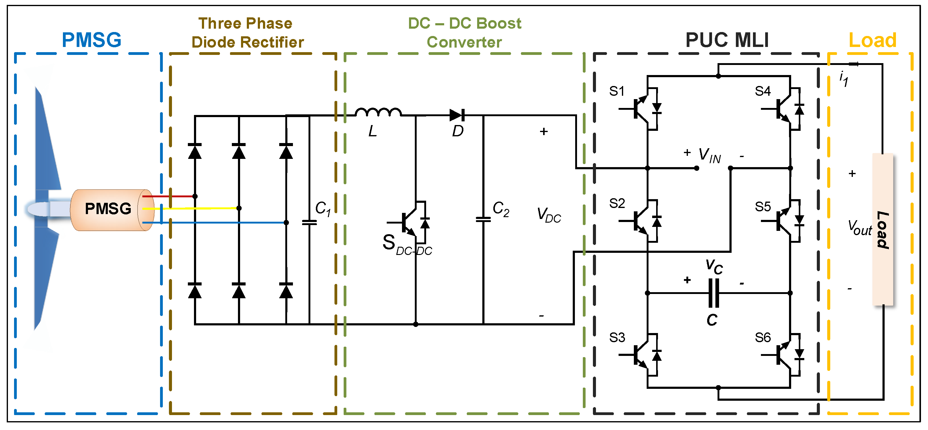
2. System Components
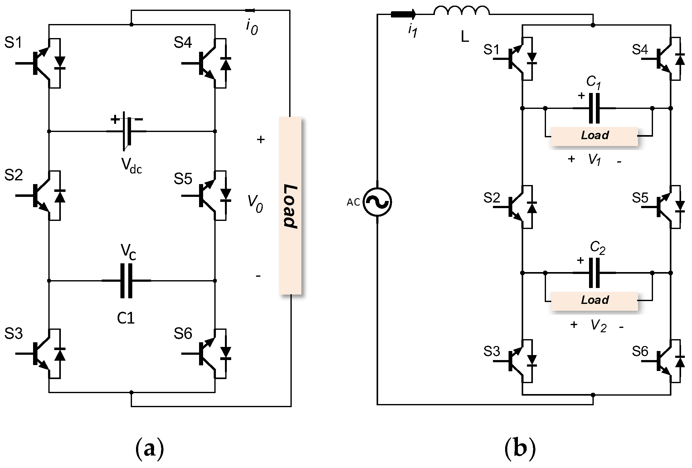
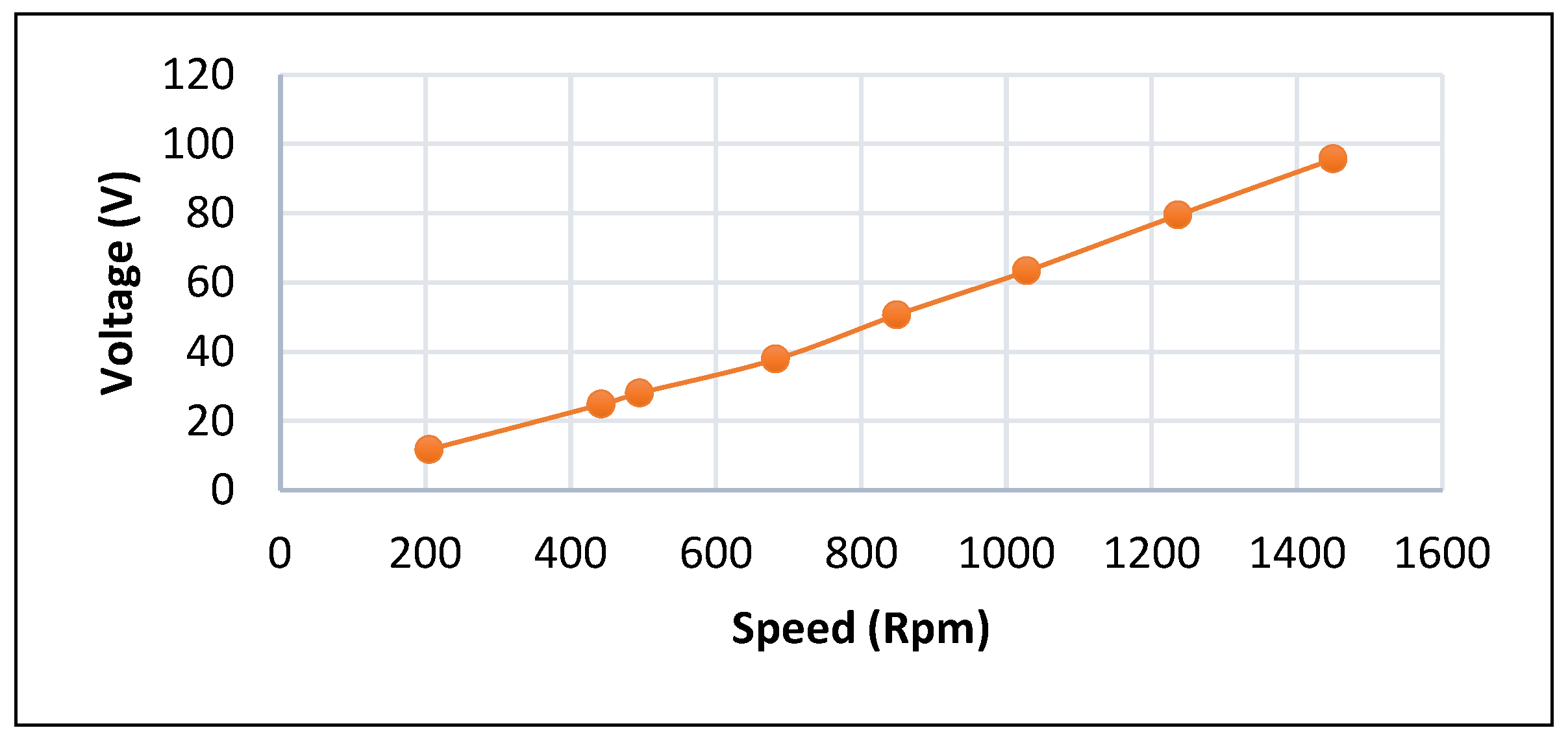
2.1. PMSG, Three-Phase Diode Rectifier, and DC–DC Boost Converter
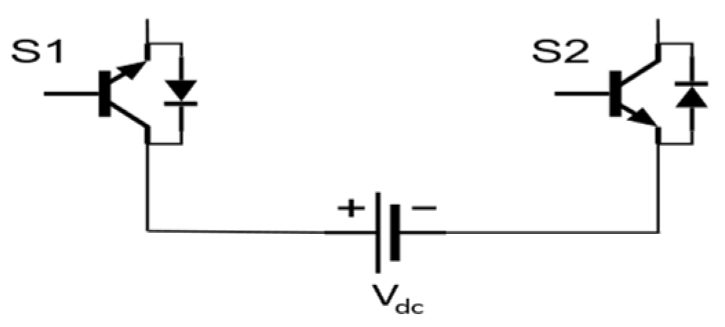
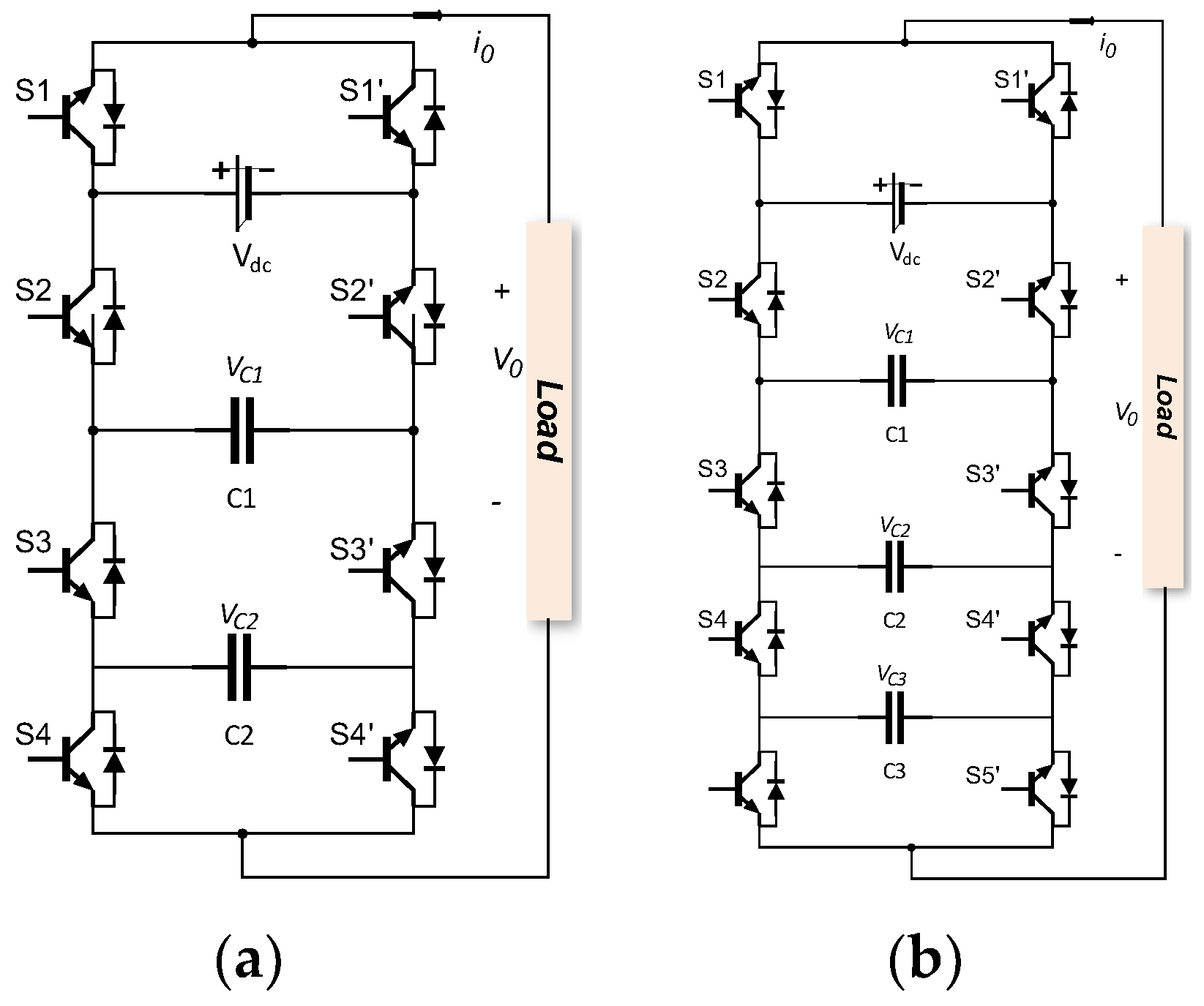
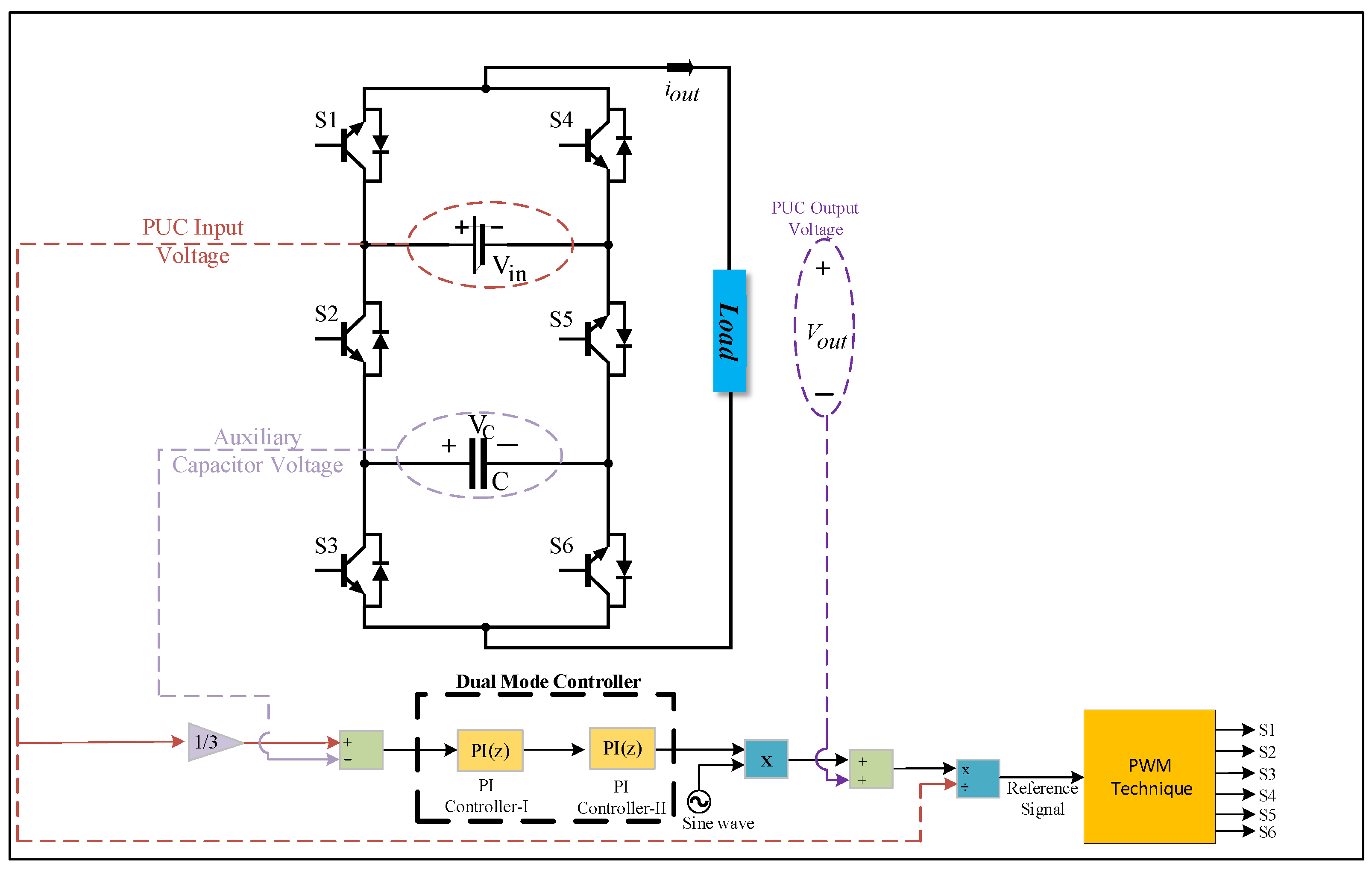
2.2. PUC MLI
3. Simulation Studies
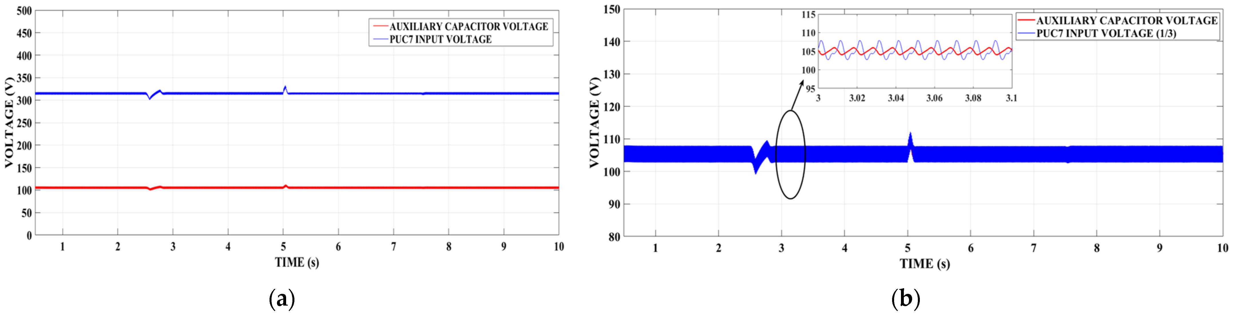
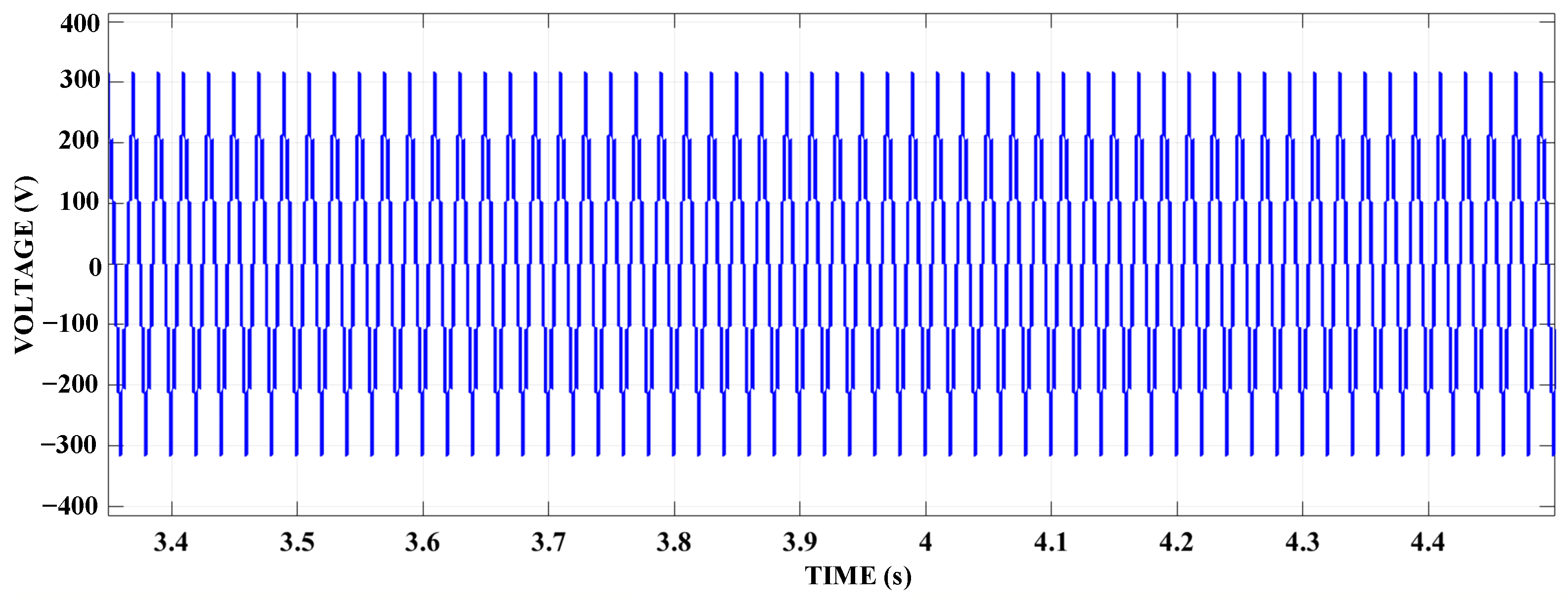
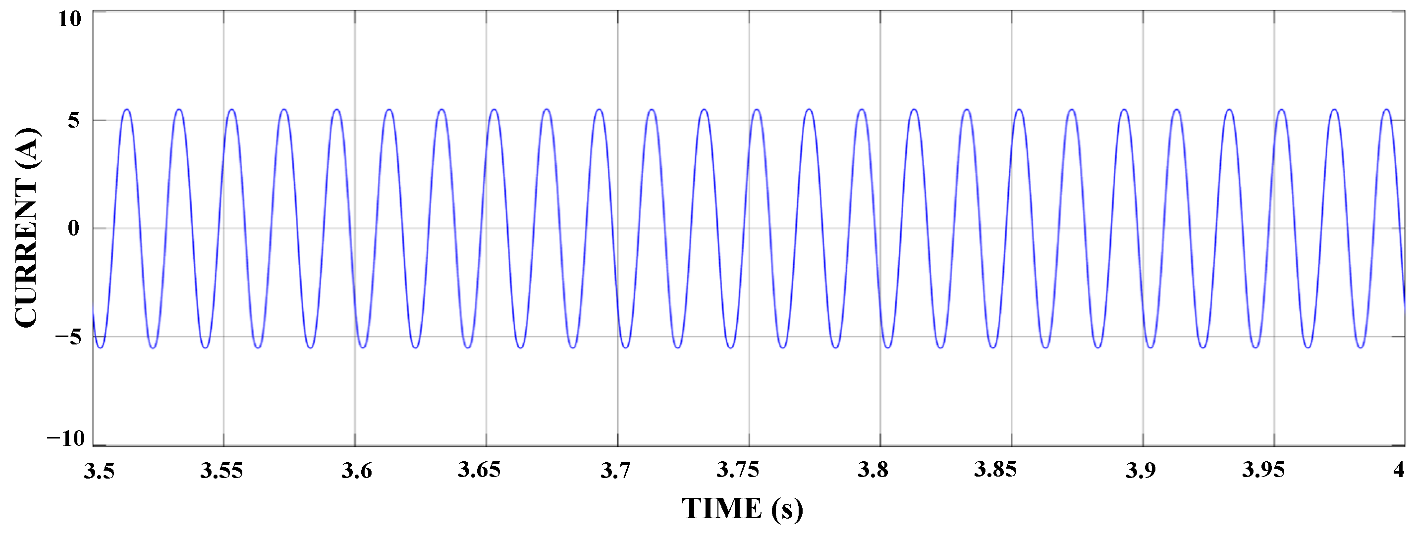
3.1. Case 1: Seven-Level PUC MLI
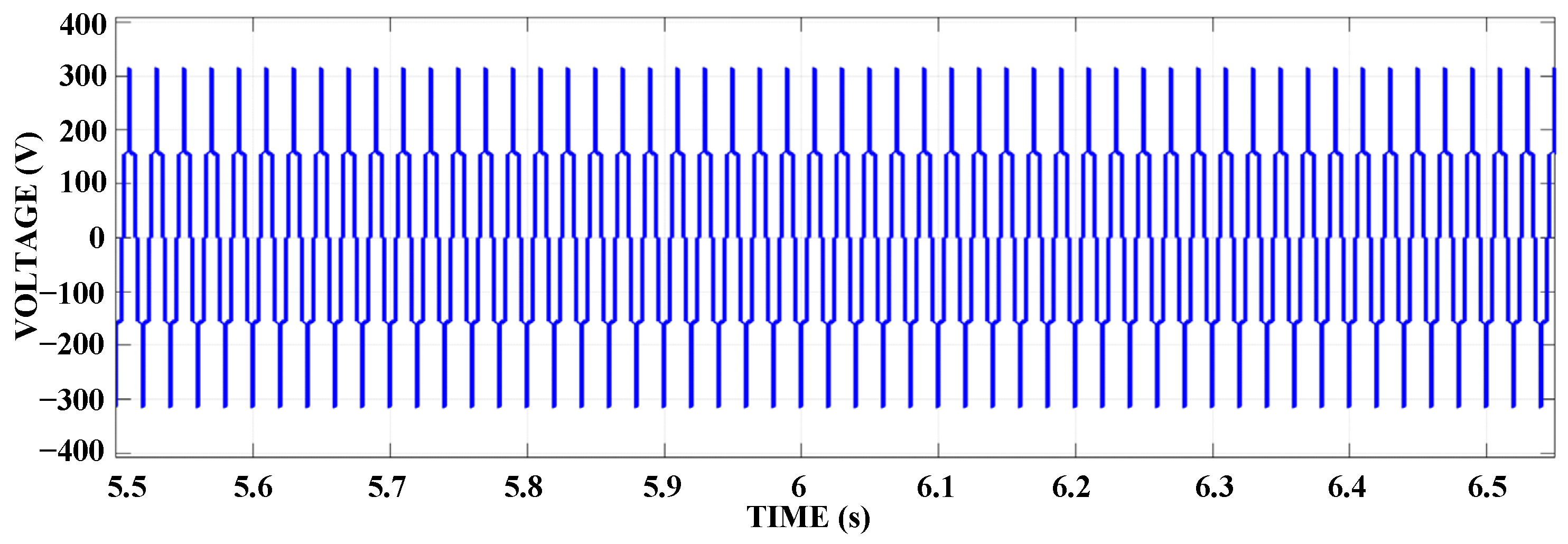
3.2. Case 2: Five-Level PUC MLI
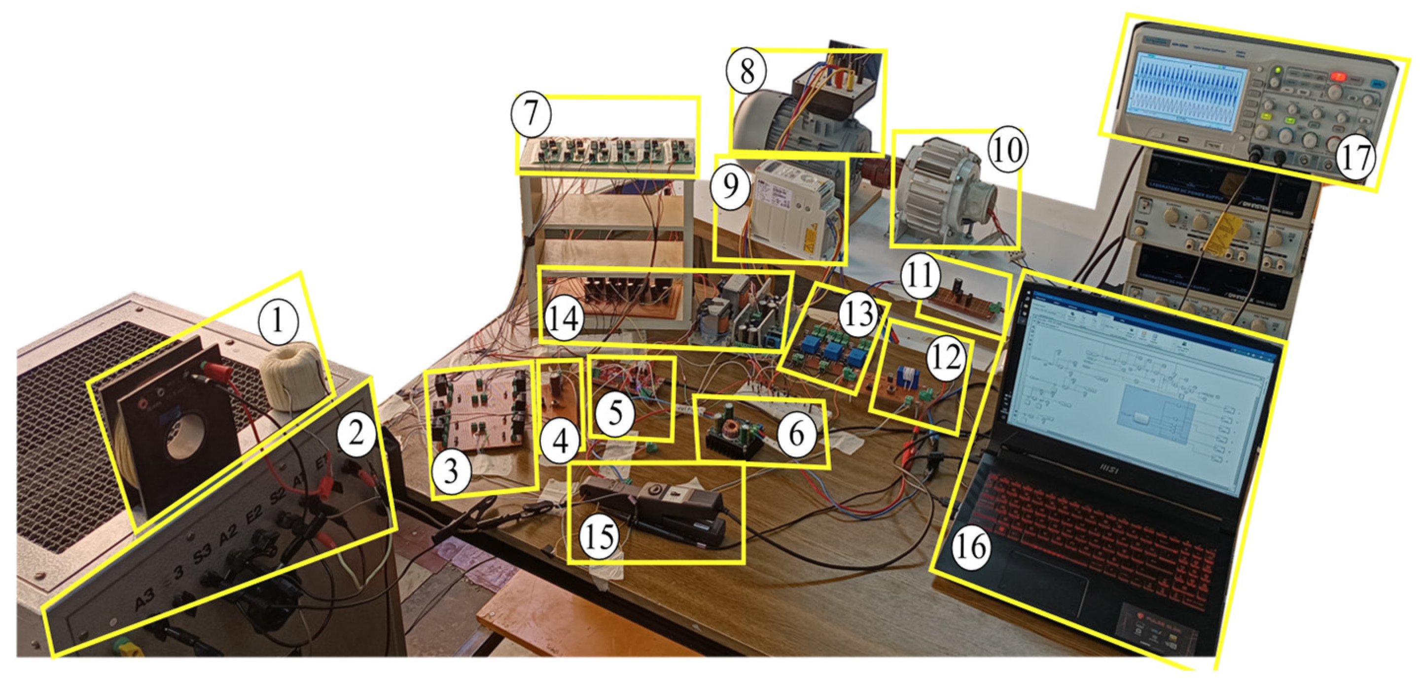
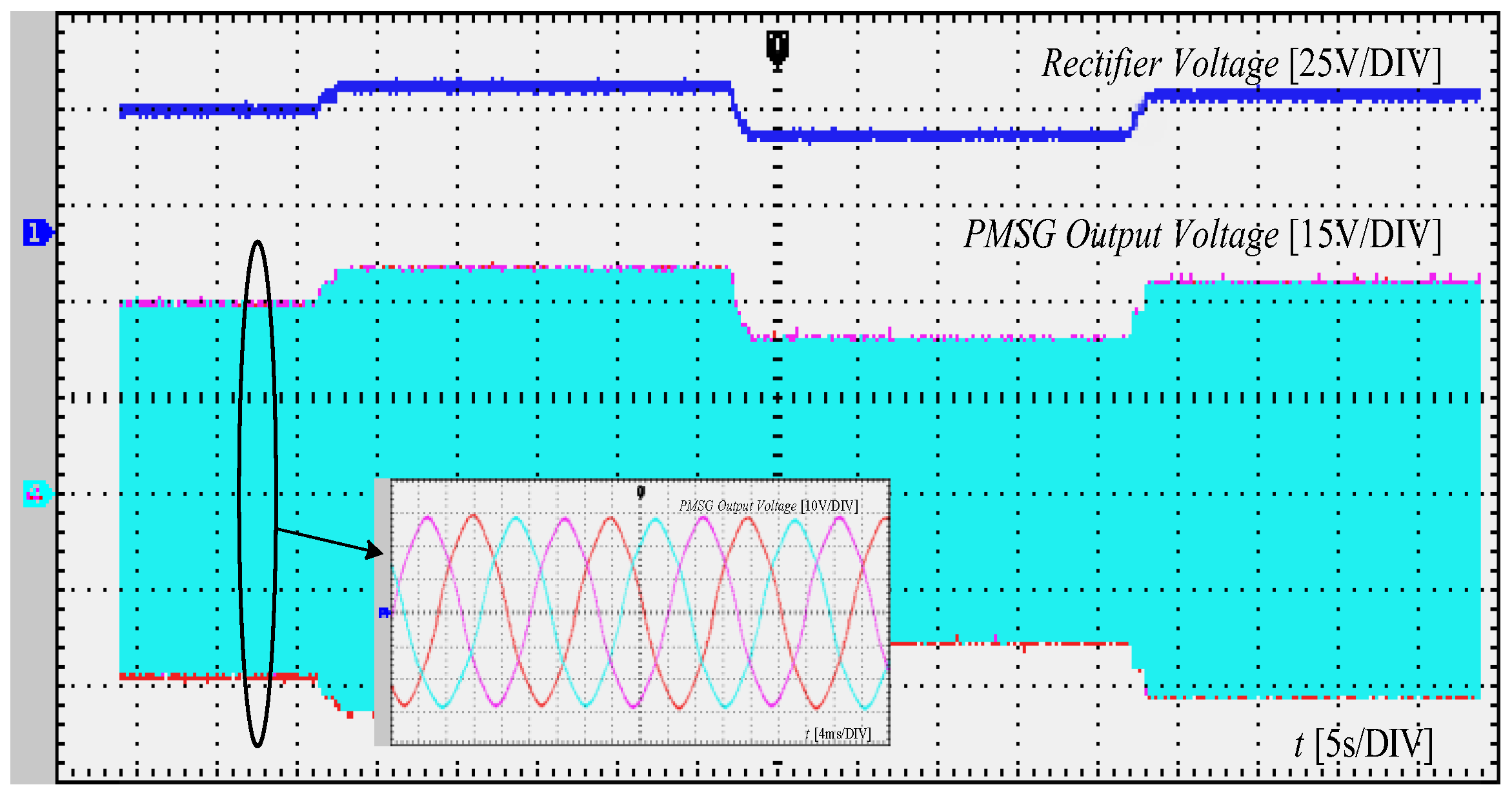
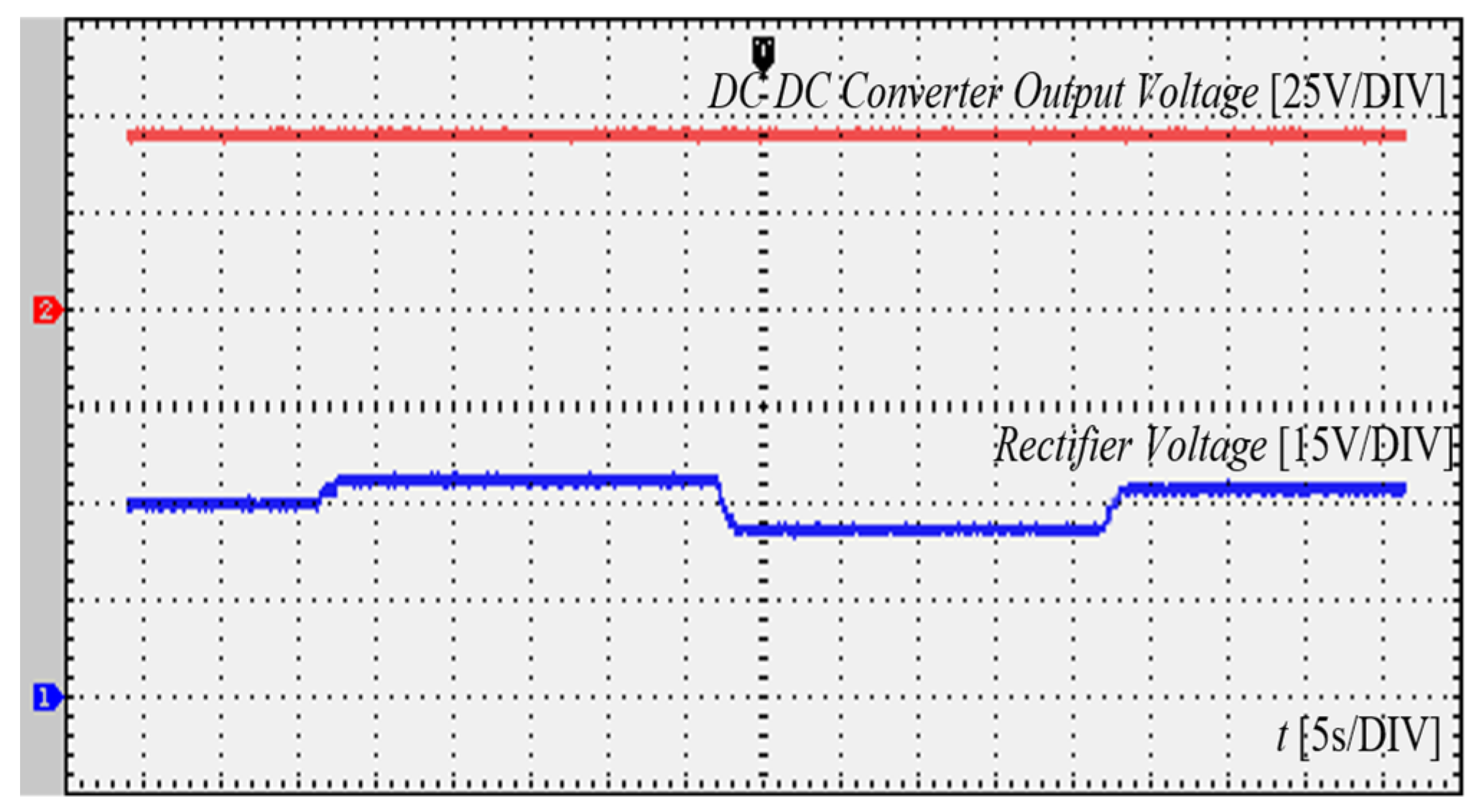
4. Experimental Studies
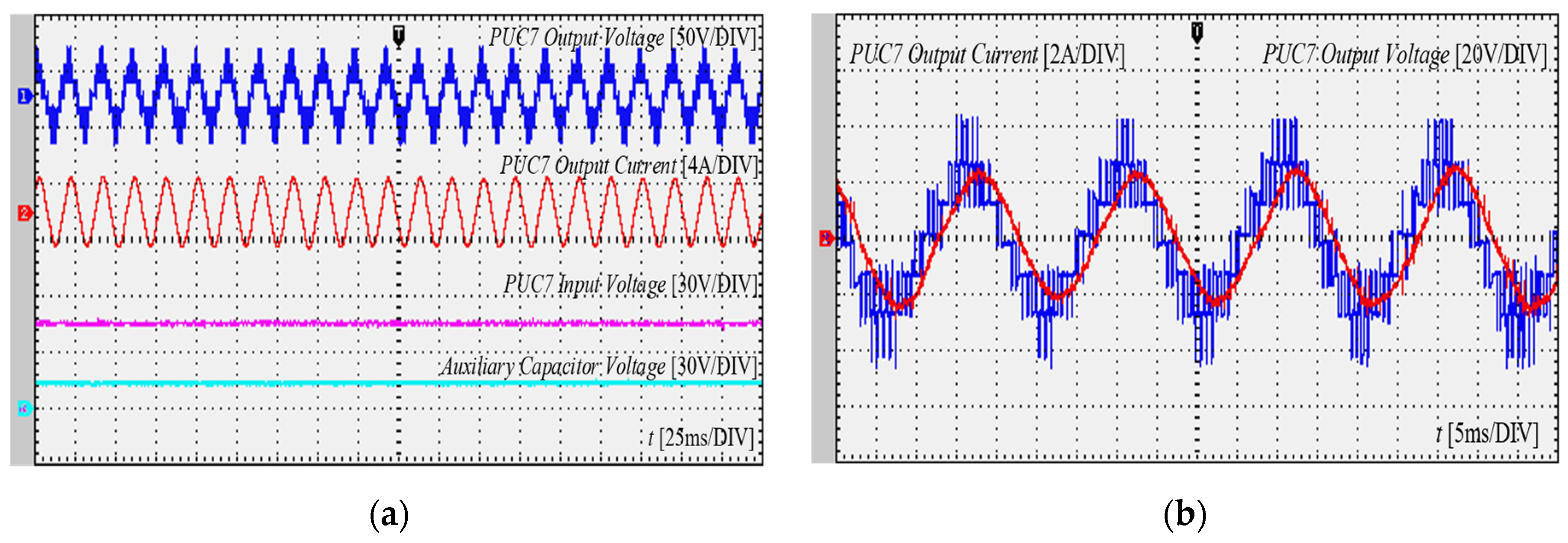
4.1. Case 1: Seven-Level PUC MLI
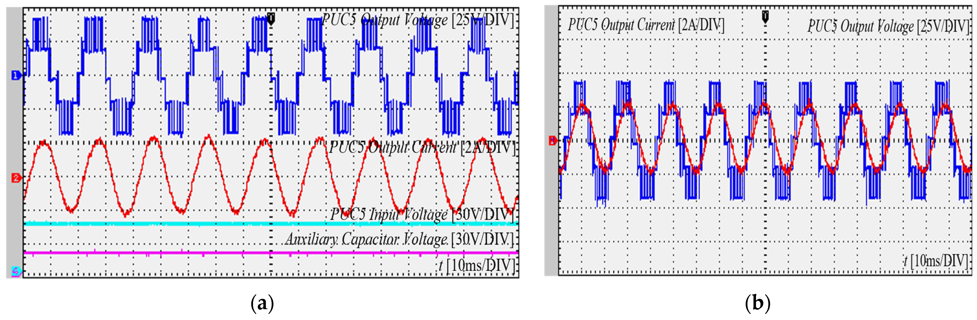
4.2. Case 2: Five-Level PUC MLI
5. Conclusions
Author Contributions
Funding
Institutional Review Board Statement
Informed Consent Statement
Data Availability Statement
Acknowledgments
Conflicts of Interest
Nomenclature
| AC | Alternative Current | A | rotor swept area |
| CHB | Cascaded H-Bridge | D | duty cycle |
| DC | Direct Current | f | frequency |
| FC | Flying Capacitor | iL | inductor current of DC–DC converter |
| FS-MPC | Finite Set Model Predictive Control | Nc | number of auxiliary capacitors |
| GWEC | Global Wind Energy Council | Nv | level of output voltage |
| IRENA | International Renewable Energy Agency | R | blade radius |
| MLI | Multilevel Inverter | V0 | output voltage |
| NPC | Neutral-Point Clamped | Vavr | average voltage |
| PMSG | Permanent Magnet Synchronous Generator | Vc | auxiliary capacitor voltage |
| PUC | Packed U-Cell | Vdc | direct current source |
| PUC15 | Fifteen-Level Packed U-Cell | Vm | peak value of the phase voltage |
| PUC31 | Thirty-One-Level Packed U-Cell | Vs | input voltage |
| PUC5 | Five-Level Packed U-Cell | Vw | wind speed |
| PUC7 | Seven-Level Packed U-Cell | ρ | air density |
| PUC9 | Nine-Level Packed U-Cell | ∆I | peak-to-peak inductor ripple current |
| PV | Photovoltaic | ∆Vc | peak-to-peak capacitor ripple voltage |
| SMC | Sliding Mode Controller | ||
| THD | Total Harmonic Distortion | ||
| WECS | Wind Energy Conversion System |
References
- Chaudhuri, A.; Datta, R.; Kumar, M.P.; Davim, J.P.; Pramanik, S. Energy Conversion Strategies for Wind Energy System: Electrical, Mechanical and Material Aspects. Materials 2022, 15, 1232. [Google Scholar] [CrossRef] [PubMed]
- Avu, B.K.; Sainadh Yelamanchili, M.; Dugyala, S.; Kethireddy, S.G.; Preetham Gajji, S.; Mishra, S. Modelling and Simulation of Wind Turbine Using PMSG. In Proceedings of the 2021 4th International Conference on Recent Developments in Control, Automation & Power Engineering (RDCAPE), Noida, India, 7–8 October 2021; pp. 16–20. [Google Scholar] [CrossRef]
- Fathy, A.; Rezk, H.; Yousri, D.; Kandil, T.; Abo-Khalil, A.G. Real-time bald eagle search approach for tracking the maximum generated power of wind energy conversion system. Energy 2022, 249, 123661. [Google Scholar] [CrossRef]
- Malozyomov, B.V.; Martyushev, N.V.; Voitovich, E.V.; Kononenko, R.V.; Konyukhov, V.Y.; Tynchenko, V.; Kukartsev, V.A.; Tynchenko, Y.A. Designing the Optimal Configuration of a Small Power System for Autonomous Power Supply of Weather Station Equipment. Energies 2023, 16, 5046. [Google Scholar] [CrossRef]
- IRENA. Available online: https://www.irena.org/Publications/2023/Jul/Renewable-energy-statistics-2023 (accessed on 9 August 2023).
- Mostafa, M.A.; El-Hay, E.A.; Elkholy, M.M. An overview and case study of recent low voltage ride through methods for wind energy conversion system. Renew. Sustain. Energy Rev. 2023, 183, 113521. [Google Scholar] [CrossRef]
- Kirgizov, A.K.; Dmitriev, S.A.; Safaraliev, M.K.; Pavlyuchenko, D.A.; Ghulomzoda, A.H.; Ahyoev, J.S. Expert system application for reactive power compensation in isolated electric power systems. Int. J. Electr. Comput. Eng. IJECE 2021, 11, 3682–3691. [Google Scholar] [CrossRef]
- Peng, Z. Modelling and Simulation of Direct Drive Permanent Magnet Wind Power Generation System Based on Simulink. In Proceedings of the 2021 2nd International Conference on Intelligent Computing and Human-Computer Interaction (ICHCI), Shenyang, China, 17–19 November 2021; pp. 344–350. [Google Scholar] [CrossRef]
- Pan, L.; Shao, C. Wind energy conversion systems analysis of PMSG on offshore wind turbine using improved SMC and Extended State Observer. Renew. Energy 2020, 161, 149–161. [Google Scholar] [CrossRef]
- Global Wind Energy Council (GWEC). Global Wind Report 2022. Available online: https://gwec.net/global-wind-report-2022/ (accessed on 10 September 2023).
- Global Wind Energy Council (GWEC). Global Wind Report 2023. Available online: https://gwec.net/wp-content/uploads/2023/03/GWR-2023_interactive.pdf (accessed on 25 September 2023).
- Yu, J.; Li, J.; Hu, W.; Zhang, G.; Wang, H.; Huang, Q.; Chen, Z. Small-signal modeling of wind farm with direct-drive PMSG using the component connection method. Energy Rep. 2021, 7, 334–342. [Google Scholar] [CrossRef]
- Osman, A.M.; Alsokhiry, F. Sliding Mode Control for Grid Integration of Wind Power System Based on Direct Drive PMSG. IEEE Access 2022, 10, 26567–26579. [Google Scholar] [CrossRef]
- Peng, X.; Liu, Z.; Jiang, D. A review of multiphase energy conversion in wind power generation. Renew. Sustain. Energy Rev. 2021, 147, 111172. [Google Scholar] [CrossRef]
- Rosyadi, M.; Umemura, A.; Takahashi, R.; Tamura, J. Detailed and Average Models of a Grid-Connected MMC-Controlled Permanent Magnet Wind Turbine Generator. Appl. Sci. 2022, 12, 1619. [Google Scholar] [CrossRef]
- Ibrahim, R.A.; Zakzouk, N.E. A PMSG Wind Energy System Featuring Low-Voltage Ride-through via Mode-Shift Control. Appl. Sci. 2022, 12, 964. [Google Scholar] [CrossRef]
- Panda, B.; Sharma, A.; Nandi, S.; Pradhan, A.; Panda, B.; Jena, C. Modelling and Control of PMSG based Wind Turbine. In Proceedings of the 2021 International Conference on Control, Automation, Power and Signal Processing (CAPS), Jabalpur, India, 10–12 December 2021; pp. 1–6. [Google Scholar] [CrossRef]
- Radhika, A.; Thenmozhi, G.; Babu, B.S.; Vidhya, V. Power Conversion in PMSG Wind Energy Conversion Systems using Trans Z Source Inverter. In Proceedings of the 2021 International Conference on Advancements in Electrical, Electronics, Communication, Computing and Automation (ICAECA), Tamilnadu, India, 8–9 October 2021; pp. 1–5. [Google Scholar] [CrossRef]
- Bakhtiari, F.; Nazarzadeh, J. Optimal Estimation and Tracking Control for Variable-speed Wind Turbine with PMSG. J. Mod. Power Syst. Clean Energy 2020, 8, 159–167. [Google Scholar] [CrossRef]
- Deng, Z.; Zhu, X.; Duan, J.; Ye, J.; Wang, Y. A Multilevel Switched Capacitor Inverter with Reduced Components and Self-Balance. Appl. Sci. 2023, 13, 8955. [Google Scholar] [CrossRef]
- Geetha, K. Implementation of Five Level Multilevel Inverter with Reduced Leakage Current. In Proceedings of the 2022 IEEE International Conference on Distributed Computing and Electrical Circuits and Electronics (ICDCECE), Ballari, India, 23–24 April 2022; pp. 1–6. [Google Scholar] [CrossRef]
- Hasirci, H.Y.; Vural, A.M. Modeling and Simulation of PMSG based Wind-Solar Energy Based Hybrid Energy Conversion System. In Proceedings of the 2022 Global Energy Conference (GEC), Batman, Turkey, 26–29 October 2022; pp. 223–228. [Google Scholar] [CrossRef]
- Al-Dori, O.; Vural, A.M. A novel control method for enhanced performance of single-phase matrix converters. Int. J. Circ. Theor. Appl. 2023, 1–26. [Google Scholar] [CrossRef]
- Kumar, D.; Nema, R.K.; Gupta, S.; Dewangan, N.K. A Fault-Tolerant Sensorless Approach in Five-Level Packed U Cells (PUC5) Multilevel Inverter. Int. J. Power Energy Syst. 2022, 42. [Google Scholar] [CrossRef]
- Ounejjar, Y.; Al-Haddad, K.; Gregoire, L.A. Packed U cells multilevel converter topology: Theoretical study and experimental validation. IEEE Trans. Ind. Electron. 2011, 58, 1294–1306. [Google Scholar] [CrossRef]
- Landry, J.; Danielle, M.; Yves, J.; Duckler, E. Control of Reduced Switches Count and Classical Multilevel Inverters: A Comparison. E3S Web Conf. 2022, 354, 02002. [Google Scholar] [CrossRef]
- Khawaja, R.; Sebaaly, F.; Kanaan, H.Y. Design of a 7-Level Single-Stage/Phase PUC Grid-Connected PV Inverter with FS-MPC Control. In Proceedings of the 2020 IEEE International Conference on Industrial Technology (ICIT), Buenos Aires, Argentina, 26–28 February 2020; pp. 751–756. [Google Scholar] [CrossRef]
- Hadmer, B.; Drid, S.; Kouzou, A.; Mechnane, F.; Chrifi–Alaoui, L.; Drid, M.D. Voltage Sensorless Sliding Mode Control for Five Level PUC Single Phase Inverter Used in PV System. In Proceedings of the 2022 IEEE 21st international Conference on Sciences and Techniques of Automatic Control and Computer Engineering (STA), Sousse, Tunisia, 19–21 December 2022; pp. 492–497. [Google Scholar] [CrossRef]
- Pourmirasghariyan, M.; Pourmirasghariyan, M.; Zarei, S.F.; Hamzeh, M.; Heidari Yazdi, S.S. A Maximum Power Point Tracking Scheme for PV Systems Using Model Predictive Control in Grid-Connected Packed U-Cell Inverters. In Proceedings of the 2022 12th Smart Grid Conference (SGC), Kerman, Iran, 13–15 December 2022; pp. 1–5. [Google Scholar] [CrossRef]
- Babaie, M.; Sharifzadeh, M.; Kanaan, H.Y.; Al-Haddad, K. Switching-Based Optimized Sliding-Mode Control for Capacitor Self-Voltage Balancing Operation of Seven-Level PUC Inverter. IEEE Trans. Ind. Electron. 2021, 68, 3044–3057. [Google Scholar] [CrossRef]
- Upreti, S.; Singh, B.; Kumar, N. Harmonics Minimization in PUC Type Solar Multilevel Converter with Multicarrier Switching Schemes. IETE J. Res. 2022, 1–10. [Google Scholar] [CrossRef]
- Noman, A.M.; Al-Shamma’a, A.; Addoweesh, K.E.; Alabduljabbar, A.A.; Alolah, A.I. Cascaded Multilevel Inverter Topology Based on Cascaded H-Bridge Multilevel Inverter. Energies 2018, 11, 895. [Google Scholar] [CrossRef]
- Lin, C.-H.; Farooqui, S.A.; Liu, H.-D.; Huang, J.-J.; Fahad, M. Finite Control Set Model Predictive Control (FCS-MPC) for Enhancing the Performance of a Single-Phase Inverter in a Renewable Energy System (RES). Mathematics 2023, 11, 4553. [Google Scholar] [CrossRef]
- Zhang, Q.; He, J.; Xu, Y.; Hong, Z.; Chen, Y.; Strunz, K. Average-Value Modeling of Direct-Driven PMSG-Based Wind Energy Conversion Systems. IEEE Trans. Energy Convers. 2022, 37, 264–273. [Google Scholar] [CrossRef]
- Thayumanavan, P.; Kaliyaperumal, D.; Subramaniam, U.; Bhaskar, M.S.; Padmanaban, S.; Leonowicz, Z.; Mitolo, M. Combined Harmonic Reduction and DC Voltage Regulation of a Single DC Source Five-Level Multilevel Inverter for Wind Electric System. Electronics 2020, 9, 979. [Google Scholar] [CrossRef]
- Mani, P.; Joo, Y.H. Fuzzy Event-Triggered Control for Back-to-Back Converter Involved PMSG-Based Wind Turbine Systems. IEEE Trans. Fuzzy Syst. 2022, 30, 1409–1420. [Google Scholar] [CrossRef]
- Uddin, M.H.; Abid, A.; Inam, U.; Urooj, A.; Siddiqui, M.R. A Comparative Analysis of a Multilevel Inverter Topology Based on Phase Disposition Sinusoidal Pulse Width Modulation. Eng. Proc. 2023, 46, 30. [Google Scholar] [CrossRef]
- Mustafa, S.; Sarwar, A.; Tariq, M.; Ahmad, S.; Mahmoud, H.A. Development and Control of a Switched Capacitor Multilevel Inverter. Energies 2023, 16, 4269. [Google Scholar] [CrossRef]
- Gopal, Y.; Kumar, Y.N.V.; Kumari, A.; Prakash, O.; Chowdhury, S.; Almehizia, A.A. Reduced Device Count for Self-Balancing Switched-Capacitor Multilevel Inverter Integration with Renewable Energy Source. Sustainability 2023, 15, 8000. [Google Scholar] [CrossRef]
- Siddique, M.D.; Mekhilef, S.; Shah, N.M.; Ali, J.S.M.; Blaabjerg, F. A New Switched Capacitor 7L Inverter With Triple Voltage Gain and Low Voltage Stress. IEEE Trans. Circuits Syst. II Express Briefs 2020, 67, 1294–1298. [Google Scholar] [CrossRef]
- Annoukoubi, M.; Essadki, A.; Nasser, T. Cascade H-Bridge Multilevel Inverter for a Wind Energy Conversion System Applications. In Proceedings of the 2021 9th International Renewable and Sustainable Energy Conference (IRSEC), Tetouan, Morocco, 23–27 November 2021; pp. 1–7. [Google Scholar] [CrossRef]
- Palani, A.; Mahendran, V.; Vengadakrishnan, K.; Muthusamy, S.; Mishra, O.P.; Ramamoorthi, P.; Maurya, M.R.; Sadasivuni, K.K. A Novel Design and Development of Multilevel Inverters for Parallel Operated PMSG-Based Standalone Wind Energy Conversion Systems. Iran. J. Sci. Technol. Trans. Electr. Eng. 2023. [Google Scholar] [CrossRef]
- Chen, M.; Gao, C.; Yin, C.; Loh, P.C. Novel Cascaded Seven-Level Inverter with Embedded Voltage Boosting for Renewable Energy Applications. CPSS Trans. Power Electron. Appl. 2022, 7, 58–70. [Google Scholar] [CrossRef]
- Zhang, W.; Wang, H.; Zhu, X.; Wang, H.; Deng, X.; Yue, X. A Three-Phase Five-Level Inverter with High DC Voltage Utilization and Self-Balancing Capacity of Floating Capacitor. IEEE Trans. Power Electron. 2022, 37, 10609–10619. [Google Scholar] [CrossRef]
- Guo, Y.; Mohamed, M.E.A. Speed Control of Direct Current Motor Using ANFIS Based Hybrid P-I-D Configuration Controller. IEEE Access 2020, 8, 125638–125647. [Google Scholar] [CrossRef]
- Mousavi, Y.; Bevan, G.; Kucukdemiral, I.B.; Fekih, A. Sliding mode control of wind energy conversion systems: Trends and applications. Renew. Sustain. Energy Rev. 2022, 167, 112734. [Google Scholar] [CrossRef]
- Errami, Y.; Obbadi, A.; Sahnoun, S. Dynamic performance analysis of grid-connected PMSG based on nonlinear control. Int. J. Ambient. Energy 2022, 43, 4675–4682. [Google Scholar] [CrossRef]
- Rashid, M.H. Power Electronics: Devices, Circuits, and Applications, International Edition, 4th ed.; Pearson: England, UK, 2014. [Google Scholar]
- Pamuji, F.A.; Ulil ‘Azmi, M.; Riawan, D.C. MPPT of 1.5 kW Wind Turbine with Pitch and Voltage Control Based on Artificial Neural Network. In Proceedings of the 2021 International Seminar on Intelligent Technology and Its Applications (ISITIA), Surabaya, Indonesia, 21–22 July 2021; pp. 40–45. [Google Scholar] [CrossRef]
- Uddin, M.J.; Islam, M.S. Implementation of Cascaded Multilevel Inverter with Reduced Number of Components. In Proceedings of the 2021 2nd International Conference on Robotics, Electrical and Signal Processing Techniques (ICREST), Dhaka, Bangladesh, 5–7 January 2021; pp. 669–672. [Google Scholar] [CrossRef]
- Hasirci, H.Y.; Vural, A.M. Power Converter Topologies for PMSG Based Wind Energy Systems: Packed U Cell Multilevel Inverter Simulation. In Proceedings of the 2021 5th International Symposium on Multidisciplinary Studies and Innovative Technologies (ISMSIT), Ankara, Turkey, 21–23 October 2021; pp. 529–534. [Google Scholar] [CrossRef]
- Zid, A.B.; Bacha, F. Simulation of a Single-Phase Seven-level Packed U Cells Rectifier: A comparative study between PWM control and Hysteresis control. In Proceedings of the 9th International Renewable Energy Congress (IREC 2018), Hammamet, Tunisia, 20–22 March 2018. [Google Scholar] [CrossRef]
- Sathik, M.J.; Bhatnagar, K.; Sandeep, N.; Blaabjerg, F. An Improved Seven-Level PUC Inverter Topology with Voltage Boosting. IEEE Trans. Circuits Syst. II Express Briefs 2019, 67, 127–131. [Google Scholar] [CrossRef]
- Mishra, N.; Singh, B.; Yadav, S.K.; Tariq, M. Power Quality Improvement in Fifteen Level PUC Converter for Solar PV Grid-Tied Applications. IEEE Trans. Ind. Appl. 2023, 59, 4264–4273. [Google Scholar] [CrossRef]
- Ounejjar, Y.; Al-Haddad, K. New Nine-Level Inverter with Self Balancing of Capacitors Voltages. In Proceedings of the IECON 2018—44th Annual Conference of the IEEE Industrial Electronics Society, Washington, DC, USA, 21–23 October 2018; pp. 4467–4472. [Google Scholar] [CrossRef]
- Ounejjar, Y.; Al-Haddad, K. A Novel 31-Level Packed U Cells Converter. In Proceedings of the 2011 International Conference on Power Engineering, Energy and Electrical Drives, Malaga, Spain, 11–13 May 2011. [Google Scholar] [CrossRef]
- Krishnamoorthy, U.; Pitchaikani, U.; Rusu, E.; Fayek, H.H. Performance Analysis of Harmonic-Reduced Modified PUC Multi-Level Inverter Based on an MPC Algorithm. Inventions 2023, 8, 90. [Google Scholar] [CrossRef]
- Sheir, A.; Orabi, M.; Ahmed, M.E.; Iqbal, A.; Youssef, M. A high efficiency single-phase multilevel packed U cell inverter for photovoltaic applications. In Proceedings of the 2014 IEEE 36th International Telecommunications Energy Conference (INTELEC), Vancouver, BC, Canada, 28 September–2 October 2014. [Google Scholar] [CrossRef]
- Sudha, V.; Vijayarekha, K.; Sidharthan, R.K.; Prabaharan, N. Combined Optimizer for Automatic Design of Machine Learning-based Fault Classifier for Multilevel Inverters. IEEE Access 2022, 10, 121096–121108. [Google Scholar] [CrossRef]
- Anees, M.A.; Mohammad, L.K.A.; Alam, M.; Chakrabortty, R.K.; Ryan, M.J. Reactive power compensation for grid by Packed-U-Cell inverter using model predictive control strategy with intelligent multi-objective scheme. J. Intell. Fuzzy Syst. 2021, 42, 793–806. [Google Scholar] [CrossRef]


| MLI | THD | Voltage Rating (V) | Switching Frequency (kHz) | Load | Ref. |
|---|---|---|---|---|---|
| CHB | 17.48% | 230 | 18 | 750 ohm, 240 mH | [35] |
| NPC | 19.14% | 750 | - | - | [37] |
| 7L-SCMLI | 11.99% | 175 | - | 150 ohm, 200 mH | [39] |
| 7L-Boost MLI | - | 100 | 2.5 | 100 ohm, 50 ohm, 100 mH, 50 mH | [40] |
| CHB | 31.44% | 200 | - | - | [41] |
| CHB | 28.49% | 200 | 2 | 20 ohm, 100 mH | [42] |
| C7L Full-Bridge MLI | - | 300 | 5 | 50 ohm, 20 mH | [43] |
| FC | 38.90% | 250 | 10 | - | [44] |
| Proposed PUC MLI | 11.65% | 45 | 4 | 30 ohm, 100 mH |
| Switching States and Output Voltage Values of PUC | ||||||||
|---|---|---|---|---|---|---|---|---|
| Seven-Level PUC MLI | Five-Level PUC MLI | |||||||
| Case | Vout | S1 | S2 | S3 | Vout | S1 | S2 | S3 |
| 1 | Vdc | 1 | 0 | 0 | Vdc | 1 | 0 | 0 |
| 2 | 2 × Vdc/3 | 1 | 0 | 1 | Vdc/2 | 1 | 0 | 1 |
| 3 | Vdc/3 | 1 | 1 | 0 | Vdc/2 | 1 | 1 | 0 |
| 4 | 0 | 1 | 1 | 1 | 0 | 1 | 1 | 1 |
| 4′ | 0 | 0 | 0 | 0 | 0 | 0 | 0 | 0 |
| 5 | −Vdc/3 | 0 | 0 | 1 | −Vdc/2 | 0 | 0 | 1 |
| 6 | −2 × Vdc/3 | 0 | 1 | 0 | −Vdc/2 | 0 | 1 | 0 |
| 7 | −Vdc | 0 | 1 | 1 | −Vdc | 0 | 1 | 1 |
| MLI Type | DC Source | Capacitor | Clamped Diode | Active Switch | Total Components | Control Complexity |
|---|---|---|---|---|---|---|
| CHB | 2 | 0 | 0 | 8 | 10 | Low |
| NPC | 1 | 4 | 6 | 8 | 19 | Very High |
| FC | 1 | 3 | 0 | 8 | 12 | Very High |
| PUC5 MLI | 1 | 1 | 0 | 6 | 8 | Low |
| PMSG | |
|---|---|
| Stator phase resistance (ohm) | 14 |
| Inductance (d,q) (mH) | 0.8 |
| Rated power (kW) | 1.5 |
| Flux linkage (V.s) | 0.175 |
| Number of poles | 20 |
| Inertia (J) | 0.089 |
| Rectifier | |
| Number of diodes | 6 |
| Diode reverse current (A) | 30 |
| Diode reverse voltage (A) | 600 |
| Max. output voltage (V) | 240 |
| DC–DC Boost Converter | |
| Inductor (mH) | 0.3 |
| Capacitor (uF) | 690 |
| Resistor (ohm) | 50 |
| Switching frequency (kHz) | 20 |
| Diode reverse current (A) | 30 |
| Diode reverse voltage (A) | 600 |
| Max. input voltage (V) | 240 |
| Max. output voltage (V) | 315 |
| PUC7 MLI | |
| Semiconductor switch | IXFH50N60P3 |
| Number of switches | 6 |
| Switch reverse current (A) | 50 |
| Switch reverse voltage (A) | 600 |
| Switching frequency (Hz) | 10 k |
| Load resistor (ohm) | 25 |
| Load Inductor (H) | 0.1 |
| Input voltage (V) | 315 |
| Max. output voltage (Vrms) | 220 |
| Parameter | Value |
|---|---|
| PMSG rated power (W) | 700 |
| Asynchronous motor rated power (W) | 1100 |
| Motor driver rated power (W) | 1500 |
| Diode rectifier reverse current (A) | 5 |
| Diode rectifier reverse voltage (A) | 100 |
| DC–DC boost converter rated power (W) | 600 |
| PUC MLI input voltage (V) | 45 |
| PUC MLI output frequency (Hz) | 50 |
| Auxiliary capacitor (uF) | 2200 |
| Switching frequency (kHz) | 4 |
| Voltage sensor, LEM LV 25-P (max V) | 500 |
| Current sensor, LEM LA 55-P (max A) | 50 |
| Load resistance (Ω) | 30 |
| Load inductance, L1, L2 (mH) | 69, 100 |
Disclaimer/Publisher’s Note: The statements, opinions and data contained in all publications are solely those of the individual author(s) and contributor(s) and not of MDPI and/or the editor(s). MDPI and/or the editor(s) disclaim responsibility for any injury to people or property resulting from any ideas, methods, instructions or products referred to in the content. |
© 2023 by the authors. Licensee MDPI, Basel, Switzerland. This article is an open access article distributed under the terms and conditions of the Creative Commons Attribution (CC BY) license (https://creativecommons.org/licenses/by/4.0/).
Share and Cite
Hasirci, H.Y.; Vural, A.M. Design and Experimental Verification of PUC Multilevel Inverter-Based PMSG Wind Energy Conversion System. Appl. Sci. 2023, 13, 13018. https://doi.org/10.3390/app132413018
Hasirci HY, Vural AM. Design and Experimental Verification of PUC Multilevel Inverter-Based PMSG Wind Energy Conversion System. Applied Sciences. 2023; 13(24):13018. https://doi.org/10.3390/app132413018
Chicago/Turabian StyleHasirci, Habip Yusuf, and Ahmet Mete Vural. 2023. "Design and Experimental Verification of PUC Multilevel Inverter-Based PMSG Wind Energy Conversion System" Applied Sciences 13, no. 24: 13018. https://doi.org/10.3390/app132413018
APA StyleHasirci, H. Y., & Vural, A. M. (2023). Design and Experimental Verification of PUC Multilevel Inverter-Based PMSG Wind Energy Conversion System. Applied Sciences, 13(24), 13018. https://doi.org/10.3390/app132413018