Abstract
In the manufacturing process of optical lenses, the lack of monitoring and detection of the central processing process leads to low processing efficiency and difficulty in ensuring product consistency. We propose a digital twin system for alignment processing to address this issue. The system adopts a hierarchical architecture based on the digital twin five-dimensional model, aiming to improve the fidelity and interactivity of the virtual model of the centring lathe by combining dimension-driven virtual models with integrated data and physical models of the turning mechanism. We have successfully achieved the semantic and physical fusion of multi-source heterogeneous data during centring processing using information models and OPC UA-based data interaction methods. In addition, we adopted the VMD-GRU method based on feature fusion for real-time monitoring of critical components of the centring lathe. Finally, we validated the feasibility and effectiveness of the digital twin system for the central lathe through development examples. The application of this system is expected to promote the digital and intelligent development of high-precision optical component processing, providing references including references for related manufacturing fields. In summary, we propose a digital monitoring and detection system for the centring process of optical lens manufacturing. The application of this system will help improve product consistency and processing efficiency while reducing risks and costs in the manufacturing process.
1. Introduction
High-precision optical components, as the core components of optical systems, are widely used in consumer electronics, astronomy, national defence and military, the biomedical industry, industrial manufacturing and other fields [1]. The functional realisation of an optical imaging system relies on lens design, which requires the optical axis of each visual component or lens to coincide with the ideal axial direction. However, the centre deviation introduced during lens machining and assembly can destroy the coaxial and rotational symmetry of the system, leading to coma, dispersion, aberration, and other aberrations, which seriously affect the final imaging quality of the optical system. The centre deviation is shown in Figure 1. The Centre process is shown in Figure 2. Compared with the traditional manual assembly method, centring turning while machining has higher centring accuracy and machining efficiency [1], so it has attracted much attention. However, centring lathe components will be ageing during the machining process, so considering the time-varying nature of the equipment and accurately monitoring the status of key components, including tools, spindles, feed systems, etc., is the key to ensuring the machining quality and efficiency [2,3].
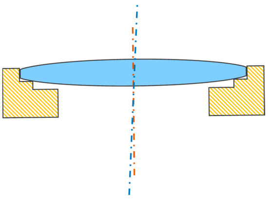
Figure 1.
The diagram of the centre deviation.
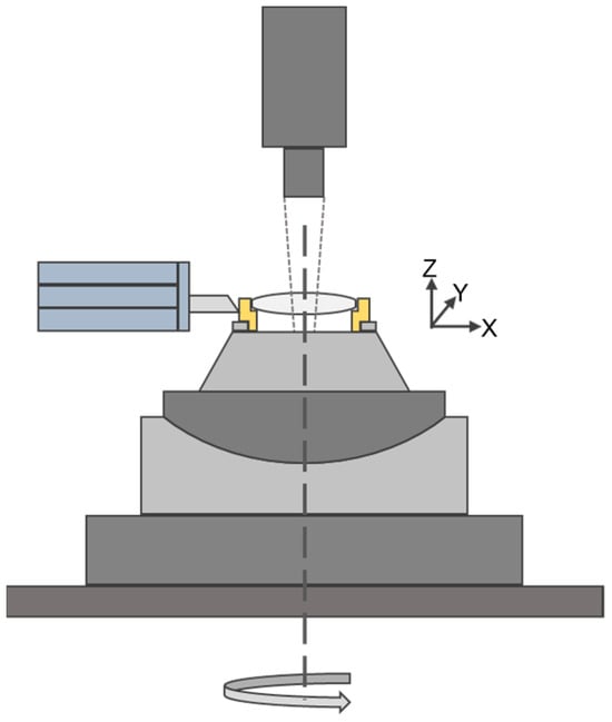
Figure 2.
The chart of the centre process.
As the key enabling technology of intelligent manufacturing, digital twin technology promotes significant changes in manufacturing technology systems and models [4,5,6,7,8]. In recent years, the related theoretical system has been improved, and the key technology of digital twins has been developed gradually [9,10,11]; digital twins have been successfully applied in the digital machining of complex equipment. Plakhotnik, D. et al. [12] elaborated on applying the digital twin concept in digital machining and investigated the digital representations of different objects involved in the machining process. Aheleroff et al. [13] proposed and developed a digital twin reference architecture and showed a significant relationship between digital twin service capabilities and large-scale personalisation, and these works laid the foundation for digital twin applications. Chao Yang et al. [14] proposed a framework for applying digital twin-based extended reality technology in the manufacturing environment, which consists of four layers, including a physical machine and its ROS-based ROS, with a digital twin. The application framework of extended reality technology is based on a digital twin with four layers, including a perception layer with physical machines and their ROS-based simulation models, a machine communication layer, a network layer containing three communication middleware, and a Unity-based service layer for creating XR-based digital applications, which improves the efficiency of extended reality application development and the usability of the HMI system.
Combining digital twins with intelligent predictive algorithms for optimising machining processes is an important research idea nowadays. In the field of centring machining, Shiau-Cheng Shiu et al. researched and developed a digital twin system for process optimisation through experiment-based genetic algorithm (DOE-GA) design, which reduced the process development time from 4 h to 1 h, reduced the entire inspection to 10% sampling inspection, and increased the yield by 20%. Lei Wu et al. proposed a hybrid deep learning model driven by digital twins, which combined the signals of motion displacement and speed during machining, accurately estimated the cutting force and predicted the wear state of diamond tools. Zhu, Z. X. et al. [15] utilised Microsoft HoloLens to develop an AR application for the digital twinning of CNC milling machines. Through visual interaction and management of digital twinning data, they improved the efficiency of the machining process.
Lu, QB et al. [16] proposed a thermal error prediction method based on the digital twin’s long and short-term memory (DT-LSTM) and developed a system for the thermal error prediction problem of thermal characterisation of the spindle of CNC machine tools. The Particle Swarm Optimisation (PSO) algorithm was used with the LSTM for thermal error prediction and fusion, which improves the accuracy and robustness of thermal error prediction. Eric J. Tuegel [17] proposed a high-fidelity digital twin model of aircraft structure, integrating the calculation of structural deflection and temperature response to flight conditions to predict the integrity and lifetime of aircraft structure. Ke Feng et al. [18] developed a digital twin-driven intelligent health management method for monitoring and evaluating the gear surface degradation process, assessing the surface wear of gearboxes, revealing the gear wear propagation characteristics, and achieving an accurate prediction of the RUL of gearboxes.
Hu, WF et al. [19] address the problem of wind speed prediction and, based on the digital twin technology, propose a hybrid time series prediction model based on the integration of the empirical modal decomposition (EEMD), the long-short-term memory (LSTM) neural network, and the Bayesian optimisation (BO). The forecasting model is comprehensively compared with methods including persistence models, ARIMA, LSTM neural networks, BO-LSTM neural networks and EEMD-LSTM neural networks through case studies.
At present, experts and scholars have begun to explore the application of digital twin technology in digital processing. Still, the research content is mainly focused on the level of model definition, system analysis, etc., which is difficult to land and promote. In this regard, this paper establishes the digital twin system architecture for the processing of high-precision optical components, constructs a high-fidelity digital twin model of a centring lathe, carries out a technical exploration of the development process of the twin model and twin data based on Unity3d, and proposes the method of VMD-GRU feature fusion to develop the digital twin intelligent service to monitor the critical components of the centring lathe intelligently.
2. Framework of Digital Twin System for the Centring Process
Tao et al. have studied the guidelines and theories for constructing digital twin systems and proposed the digital twin five-dimensional model, which abstracts the digital twin system into the following five-dimensional model [20]:
PE refers to a physical entity, VE refers to a virtual entity, SS refers to service, DD refers to twin data, and CN refers to connection. In this paper, concerning the five-dimensional model of the digital twin, we propose a layered architecture of the digital twin for the centring lathe, as shown in Figure 3. The first layer is the hardware layer, i.e., hardware such as the device body and various sensors, including the vertical turning axis system, the axis system for measurement, the four-degree-of-freedom adjustment platform, confocal non-contact sensors, force sensors, acceleration sensors, and acoustic emission (AE) sensors. The second layer is the virtual layer, i.e., the high-fidelity virtual model of the centring lathe, including the virtual model that portrays the spatial features, the physical model that reflects the thermal, mechanical, and motion laws of the object, and the behavioural model that represents the constraints of the object’s movements. The third layer is the data layer, which will include the cutting force, acceleration, acoustic emission, and other signals collected by sensors to model the information of the equipment state process data of the centring lathe and transmit the data based on the communication scheme of OPC UA. The fourth layer is the application layer, which develops intelligent services such as machining process visualisation, condition monitoring of critical components, machining process planning, and so on by invoking the data-driven high-fidelity virtual model that is oriented to the actual demand and combining various algorithms.
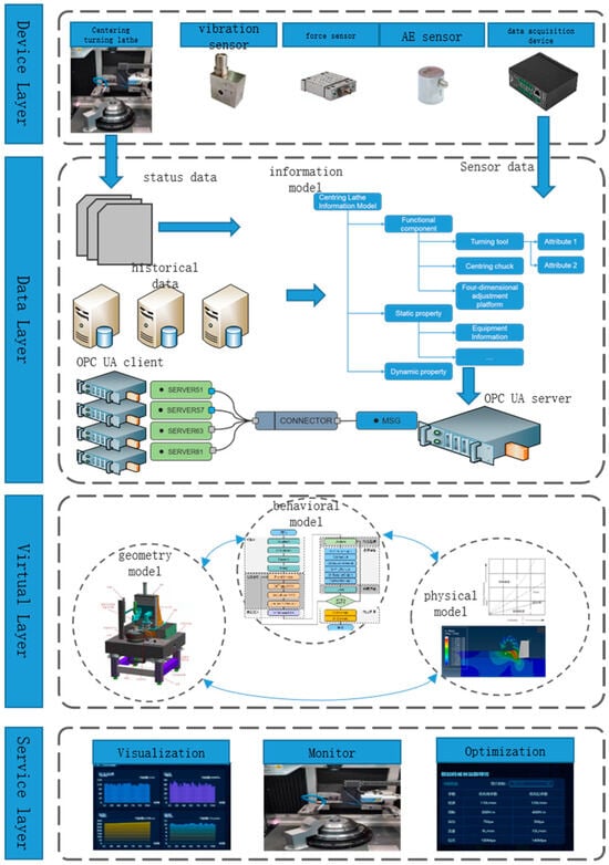
Figure 3.
The digital twin system framework of the high-precision lens centring process.
3. High-Fidelity Digital Twin Construction Methods
Based on the above digital twin architecture, the implementation methods of the data, virtual, and application layers of the centring processing digital twin system were studied. For the construction of a high-fidelity digital twin virtual model in the virtual layer, Unity3d [21,22] digital twin development tool is used to implement and integrate the virtual model, physical model, and behavioural model. For the mapping process of twin data in the data layer, it is analysed and pointed out that the key to twin data is to solve the problem of information silos in the life cycle of the equipment; the information model is used to standardise the data, and OPC UA technology is used to realise the real-time mapping of twin data [23]. Finally, the service development of the application layer is carried out, and the intelligent monitoring function of the critical components of the centring lathe is achieved based on the VMD-GRU feature fusion method.
3.1. High Fidelity Digital Twin Construction Methods
- (1)
- Virtual model
The virtual model of the centring lathe can provide a visual display of the equipment’s structure and a basis for the construction of the subsequent physical model and behavioural model. In constructing the virtual model of the centring lathe, not only should the accuracy of the model meet the requirements, but also the model should be compressed and simplified to ensure the system’s operational efficiency. In this paper, a high-fidelity virtual model of a centring lathe is constructed by combining the digital twin virtual model development tool, and the process is shown in Figure 4. First of all, according to the actual geometric dimensions of the parts and the assembly relationship used to draw the centring lathe CAD model, with the help of the Pixyz tool plug-in to import CAD files, mesh size, and quality control, to optimise the model, including mesh merging, standard adjustment, new UV, creating materials, set lighting, and so on, the model output will be imported into Unity3d, according to the actual relationship between the equipment’s movement of the model’s hierarchy planning and adjustment. The model output is imported into Unity3d, and the model layers are planned and adjusted according to the actual motion relationship of the device.
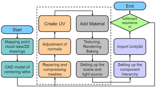
Figure 4.
The workflow of making a geometry model.
- (2)
- Behavioural model
The interactivity of the digital twin model is improved by constructing behavioural models that provide feedback responses to internal events and external inputs [24]. The key to its construction is to accurately describe the action behaviour and sequence of the device and its components. By establishing a GameObject, the virtual model is coupled using the Mesh component, and the spatial position and assembly hierarchy of the centring lathe and each part are mapped using the transform component. Create a C# script that inherits the MonoBehaviour base class, mounts it to the GameObject, divides the different phases in the behaviour, and executes the corresponding functions. In the initialisation phase, the three tasks of Awake(), OnEnable(), and Start() are completed sequentially. Awake() mainly performs operations, including obtaining components, initialising variables, etc. OnEnable() especially enables functions such as turning on the helper program, playing sound effects, etc. After the script is instantiated, it calls OnEnable() and Start(). After the hand is instantiated, Start() is called to initialise the Gameobjectand play the animation. The physical calculation stage mainly includes the FixedUpdate() function, compared with the Update in the later stage; its difference is the calling interval. FixedUpdate () is called at a fixed interval instead of once per frame, so it is often used to move the rigid body; collision monitoring and other physical functions are executed here. The Logic update stage mainly includes updating parameters, primarily to achieve the reading of data and the execution of action, the simulation of centring adjustment, and the turning machining action. The graphics rendering stage includes scene rendering, with OnRender() and OnGUI () rendering two parts. Finally, the selection judgment of whether to continue updating is carried out; if yes, then return to the physical calculation stage, execute OnDisable() to turn off the script, and finally execute OnDestroy () to deconstruct the hand to end the script’s life cycle, as shown in Figure 5.

Figure 5.
The workflow of the behavioural model.
- (3)
- Physical Model
The physical model describes the mechanism of motion, heat transfer, stress-strain, and processing deformation. Unity3d provides an excellent management mode, i.e., Physics Manager. Through the Rigidbody component in Unity3d, set the object’s mass, drag, and angular drag, and use the gravity and other parameters to realise the simulation of the object’s dynamics. In addition, the physical model is constructed by combining industrial-grade simulation software. Taking Matlab as an example, the engine instance is created by determining the communication data format and protocol, then using Matlab’s COM interface to create an engine instance, and then using C# to call the Matlab function in Unity to carry out the simulation calculation. According to the simulation results, the data is mapped using texture mapping, and the colour’s attribute is assigned a value through the mesh filter colours to visualise the simulation results.
3.2. Digital Twin Data Mapping Methods
The ultimate goal of the digital twin is to provide real-time, efficient, and intelligent services such as monitoring, diagnosis, and decision-making, which require a large amount of data. In addition, the digital twin model is also a dynamic rather than static model and requires data access to update the model dynamically. That is, twin data is the key to the digital twin system. In the process of constructing a digital twin system, due to the diversity of devices in hardware, software, connection mode, and communication protocols, i.e., data acquisition mode, the data has the characteristics of multi-source heterogeneity, which is eventually manifested in the phenomenon of data silo including the physical level and the logical level. The so-called physical data silos, that is, in the data at different stages, different departments independent of each other store and maintain the formation of the physical sense of the island. The logical data silo refers to the same data in the definition, and the understanding will be different because of different stages, equipment, departments etc., that is, the data in the logical semantics can not interact. Jagusch et al. [25] proposed a method to map the digital threads in shipbuilding and use them for the digital twins to create a consistent data model and optimise the process control. To solve the data silo problem of industrial equipment, this paper is based on the OPC UA information model [26] and proposes to instantiate the information model of centring turning processing according to specific application scenarios, represent the events and data of the processing process as an object, and give the object variables, events, and methods, and realise the interconnection between these things through the referencing, and ultimately form a set of standard data parsing and organisation models to learn the semantic interoperability of multi-source and heterogeneous data. Semantic interoperability of heterogeneous data. OPC UA technology is used to map the information objects to the address space, the description and access to process data is realised through OPC DA, the report and access to vertical data is learned through OPC HAD, and OPC A&E provides the information interface of running events and alarms.
- Centring process information model
In this paper, the standard machine tool manufacturing information model is modified and extended to propose the information model of the centring turning machining process, and the tree structure is used to describe it, as shown in Figure 6. The information model has three elements: information object, attribute, and attribute set. Among them, information objects are conceptualised descriptions of real or abstract entities of the machining process, such as spindles, chucks, and process documents. Attributes are textualised or digitised reports of the nature and characteristics of the information objects. An attribute set is a collection of features. The information model is instantiated according to the above definition to obtain the centring machining system information model with practical significance, as shown in Figure 6.
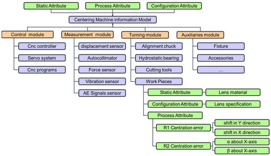
Figure 6.
The information model of a digital twin for the high-precision lens centring process.
- 2.
- Data communication scheme based on OPC UA
OPC UA is a new generation of service-oriented cross-platform transmission and transmission process security communication solution in the manufacturing field developed based on OPC Classic, which supports a variety of data semantics and information models and can unify the communication mechanisms and data interaction modes of different industrial devices to solve the data transmission and communication problems of processing. C/S structure, i.e., client/server structure, is adopted to realise the OPC UA system. The OPC client we built includes application programs, communication stacks, and client APIs to send and receive OPC UA service requests to and from the OPC UA server. The OPC UA server we built includes the OPC UA server application, communication stack, address space, publish/subscribe entity, and server interface API, and the running process of the client and server is shown in Figure 7.
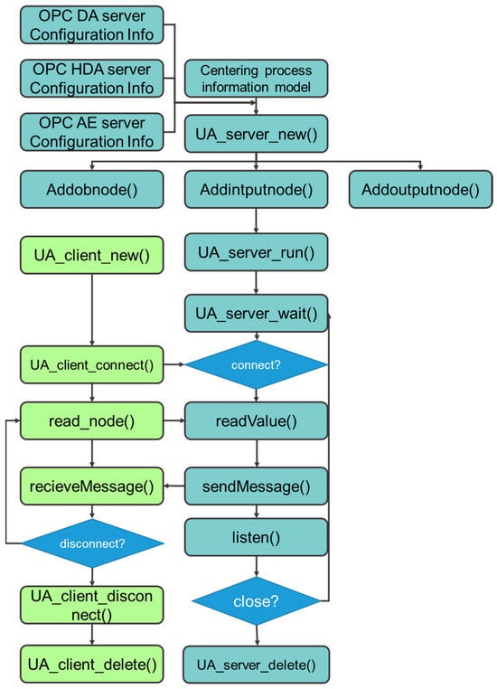
Figure 7.
The workflow of the OPC UA Client and Server.
3.3. VMD-GRU Intelligent Monitoring Approach
The digital twin system provides accurate and reliable intelligent services for manufacturing, operation, and maintenance stages to optimise the machining and manufacturing process to achieve smart manufacturing. Current research on digital twins focuses on the level of model frameworks and less on the development of actual intelligent services, which is an important reason why digital twins are difficult to promote. With the machining process, the critical components of the equipment change as the wear of the tool has an essential impact on the quality of the workpiece, so it is important to monitor the status of the device to ensure the quality of machining and improve productivity. Tool condition monitoring methods have direct and indirect ways; the implementation of the direct plan has high costs and affects the continuity of machining, so the application has been limited, while the indirect method is through the sensor acquisition of displacement, force, acoustic emission, spindle power, and other signals to monitor the amount of tool wear indirectly. In this paper, based on the digital twin system mentioned above, an intelligent monitoring service for the state of the device, a vital component of the machining system, is developed for the centring machining process. Firstly, the time-frequency domain edge components of the sensed data are extracted using the variational modal decomposition (VMD). Then the input eigenvectors are constructed by normalising them, and finally, the wear amount is predicted using the GRU’s sequential model.
Sensor data have a low data value density due to a large amount of random background noise and repetitive, redundant data and also due to the complex coupling relationship between various signals. Therefore, the sensed data must be processed to accurately extract the practical components to construct suitable features as model inputs, which is crucial for the final effect of monitoring.
Firstly, suitable signal processing methods are chosen to convert the signals. In the time series signal analysis, there are three main extraction methods commonly used: the method of time domain analysis, the technique of frequency domain analysis, and the method of time–frequency domain analysis. Among them, the process of the time domain analysis and frequency domain analysis is to decompose the signal in the time domain and frequency domain, respectively, which is suitable for dealing with smooth movements. In this paper, the monitoring of the components, due to the damage processed by the members, will change the frequency domain characteristics, which belong to the typical non-smooth signal. Therefore, this paper adopts the time–frequency domain analysis method for non-smooth signs. The vibration signal’s inherent modal component, the IMF component, is extracted using the variational modal decomposition (VMD) method [27]. The basic idea is to assume that all IMFs are bandwidth-limited components near their centre frequencies so that the sum of the estimated bandwidths is minimised, which translates into the following constrained variational problem:
It is realised as follows:
initialise the parameters.
2. update the parameters cyclically,
3. judge whether the convergence condition is satisfied, then end and output the result; otherwise, repeat step 2.
Then, through the extraction of the statistical characteristics of the signal in the time domain, frequency domain, geometric features and information features, achieve the initial screening of the data features to complete the dimensionality reduction of the data. Finally, the parts are selected for splicing, as shown in Figure 8.
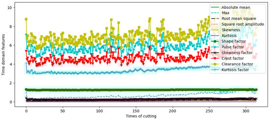
Figure 8.
Partial time-domain features obtained by VMD extraction.
Recurrent neural networks can effectively capture the time-varying nature of equipment by passing the output and state of the current moment as input to the next moment and thus are widely used in the state prediction of equipment. To improve the representation ability of the model, the number of layers of the RNN is usually superimposed, but the increase of computational depth will lead to a series of gradient problems and thus make it difficult or even impossible to train the model. LSTM uses the gating mechanism, which solves the gradient problem to a certain extent. However, the large number of parameters in LSTM leads to a large amount of computation in the training process, and there are limitations in the real-time training and calculation of the model. GRU replaces the forgetting gate and input gate in LSTM with a single forgetting gate and adds some other minor changes, which are a simplified variant of LSTM. GRU has a faster convergence speed with fewer parameters than LSTM, and the effect of GRU is not as good as that of LSTM for different tasks and datasets; and datasets are not significantly different. Therefore, GRU is used as an alternative to LSTM in this paper. The structure of GRU is shown in Figure 9, and the calculation formula is as follows [28]:
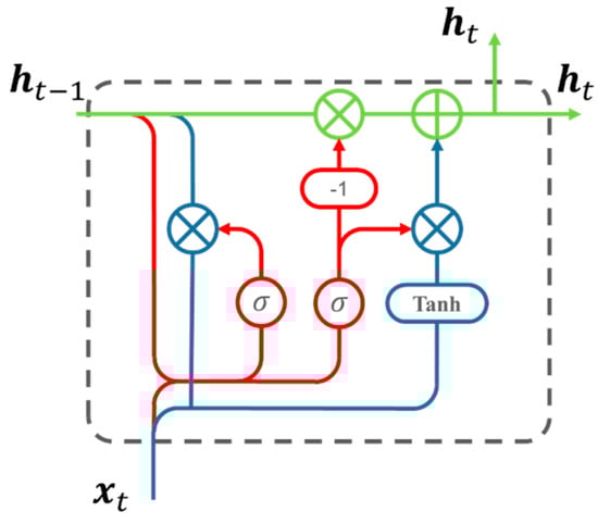
Figure 9.
Structure diagram of GRU.
4. System Implementation and Verification
4.1. Application Case
This paper takes the centring machining system as the application object. It carries out the digital twin system design based on the above digital twin system framework, and the configuration information of the system operation platform is shown in Table 1.

Table 1.
Development Platform Configuration Information.
PixyzStudio and other tools were used to develop a digital twin system for centring and machining lathes for high-precision optical components. The development process is as follows: draw a high-fidelity CAD model that reflects the spatial features of the centring lathe according to the actual drawings through Solidworks2019, then import the model into PixyzStudio, simplify the non-critical features to reduce the rendering consumption, triangulate the CSG model using the Tessellate method, merge the parts, unify the pivot, create UVs and export them to Unity3D, create a digital twin of a high-precision optical component, and export as an FBX model. Then the FBX model is imported into Unity, the digital twin scene is created, objects and textures are added, the physics engine provided by Unity is used to add components, and the physical and motion simulation is performed; a script is written in C# to control the simulation and interaction, OPC UA is registered, and the socket object is created in the hand to complete the TCP connection. The interface is connected through the OPC UA transfer protocol to get the centring lathe, including spindle position coordinates, speed, power, and other equipment state information, to complete the data connection. It will accept the data by the information model into a CRUD such as a database, using C# scripts to call MySQL for the data interaction connection. The centring lathe digital twin system is shown in Figure 10.
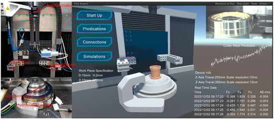
Figure 10.
The main interface of the digital twin system for the high-precision lens-centring process.
This paper uses the public dataset PHM2010 to construct the VMD-GRU deep learning model to verify the prediction effect of the equipment machining state. Repeat six trials under the above cutting conditions to obtain six sets of data, C1, C2, C3,..., C6. In this paper, C1 is selected as the training data, and C4 is selected as the test data. Each data group consists of two parts with 316 files, including one prediction output file and 315 prediction input files. The input files include 315 groups of tool wear values in X, Y, and Z directions, respectively, and each input file contains seven signal channels: force signal, vibration signal, and acoustic emission signal in XYZ direction. Some of the VMD decomposition results are shown in Figure 11.
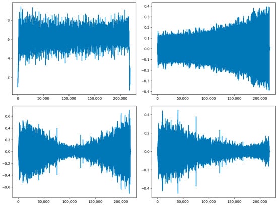
Figure 11.
The result of VMD decomposition.
The prediction results are shown in Figure 12. Figure 13 shows the RMSE and MAE of the different models in the three experiments. It is easy to see that the VMD-GRU method proposed in this paper exhibits good prediction performance. However, the LSTM has more parameters than the GRU to capture more temporal features and learn more complex patterns, thus showing better performance. It requires more data and computational resources, and in the case of a relatively short sequence, its performance is not stable enough, and it is prone to overfitting. The VMD-GRU method can mine more sequence information through VMD signal decomposition and effectively suppress the influence of noise in the original signal to obtain more relevant features, so it shows better prediction performance. At the same time, in terms of training time, it performs superior to that of the LSTM and close to that of the GRU, which meets the real-time requirements of the system’s intelligent monitoring.
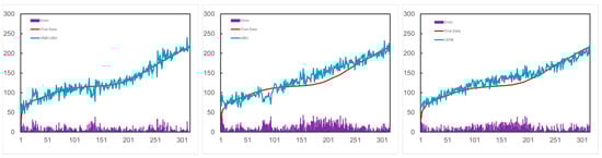
Figure 12.
The result of the VMD-GRU intelligent monitoring approach.
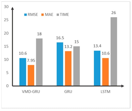
Figure 13.
Evaluation results.
4.2. Analysis of Results
The benefits of the digital twin system were tested by running it on an actual production line, which showed that the average machining time was reduced by 8.4%, but the quality of the processed products was not significantly improved. We followed up the experimental results and reviewed the relevant generation records and proposed that the efficiency improvement was mainly brought about by two aspects. On the one hand, the system can effectively monitor the status of the equipment, reducing unnecessary downtime such as stopping and failing to change tools in time, while the visualization of the interaction can assist workers to operate more skilfully. However, the consistency of the processed products is not significantly enhanced due to the short testing time and the fact that the machining accuracy of the equipment used in the case is well maintained.
5. Conclusions
This paper takes the centring process of high-precision optical components as the research object, based on the proposed digital twin system for high-precision optical components and based on the five-dimensional model of the digital twin. This is in addition to, designing the four-layer architecture including the hardware layer, data layer, virtual layer, and application layer, respectively, and carrying out research and case development validation on the method of constructing high-fidelity digital twins, the mapping of the twin data, and the intelligent monitoring of critical components.
The figure shows the results by comparing the VMD-GRU intelligent monitoring method proposed in this article with the prediction results of other methods. Regarding training time, the proposed method is 18 s, better than LSTM’s 26 s and slightly worse than GRU’s 15 s. In terms of measuring prediction accuracy, we chose RMSE and MAE as the two indicators, and it can be seen that the method proposed in this article achieved the best results of 10.6 and 7.95. However, considering the relatively small data volume (<1000) in this experiment, the performance of the LSTM method has not been fully demonstrated. Therefore, the method proposed in this article may not have the apparent superiority in prediction accuracy compared to LSTM, as shown in the figure.
This study combines the processing of high-precision optical components from the perspective of the system construction of the proposed digital twin framework, again based on high-fidelity models, and the visualisation of the processing process and other services, not only for the application of digital twins in the field of high-precision machining to provide a demonstration, but also to practise Industry 4.0 in the manufacturing industry as for the in-depth application of information and communication technology to promote the concept of manufacturing intelligence; to accelerate the realisation of Industry 4.0, a preliminary exploration has been made. However, in this study, the model and accuracy and operational efficiency of the system needs to be further improved. At the same time, understanding how to optimise the construction process of the digital twin system, reduce its development cost, and use AR and other technologies to improve its interactive performance to minimise the difficulty of use, is a significant development direction for the future of the digital twin system of high-precision optical component machining.
Author Contributions
Conceptualization, Z.C.; methodology, Z.C. and Y.L.; validation, Z.C., Y.L. and Y.L.; writing—review and editing, Z.C., Y.L., G.M., Y.W. and B.Q.; supervision, Y.L.; project administration, Y.L.; funding acquisition, Y.L. All authors have read and agreed to the published version of the manuscript.
Funding
The authors are grateful for the financial support from the National Key R&D Program of China (2022YFB3706604) and Sichuan Provincial Science and Technology Achievement Transfer and Transformation Demonstration Project (2023ZHCG0029); and Sichuan Science and Technology Program (2022YFG0064).
Institutional Review Board Statement
Not applicable.
Informed Consent Statement
Not applicable.
Data Availability Statement
The data are available from the corresponding author on reasonable request. The data are not publicly available due to privatcy.
Conflicts of Interest
The authors declare no conflict of interest.
References
- Mcguire, J.P.; Bentley, J.; Gupta, A.; Youngworth, R.N. Manufacturable Mobile Phone Optics: Higher Order Aspheres Are Not Always Better. Proc. SPIE Int. Soc. Opt. Eng. 2010, 7652, 76521–76528. [Google Scholar]
- Wang, Y.Q.; Liu, W.Q.; Meng, X.X.; Fu, H.Y.; Zhang, D.L.; Kang, Y.S.; Feng, R.; Wei, Z.L.; Zhu, X.Q.; Jiang, G.H. Development of an immersive virtual reality head-mounted display with high performance. Appl. Opt. 2016, 55, 6969–6977. [Google Scholar] [CrossRef] [PubMed]
- Yang, J.-P.; Chen, L.; Gu, X.-B.; Zhao, Z.-Y.; Fu, C.-H.; Yang, D.-S.; Tian, D.-Z.; Chen, Z.-S.; Xie, H.-P. Hollow glass microspheres/silicone rubber composite materials toward materials for high performance deep in-situ temperature-preserved coring. Pet. Sci. 2022, 19, 309–320. [Google Scholar] [CrossRef]
- Gebhardt, A.; Schmidt, E.; Hertel, T.; Kirschstein, S.; Gebhardt, E.; Rendel, T.; Gawronski, U.; Wand, V. Alignment turning and assembly of the Sentinel 4 optical modules. Proc. SPIE 2021, 11852, 1148–1158. [Google Scholar] [CrossRef]
- Liu, H.; Zhang, S.; Li, Z.; Luan, X. Tool Wear Condition Monitoring Using Improved CNN-BiLSTM Modeling. China Mech. Eng. 2022, 33, 1940. [Google Scholar]
- Wu, L.; Leng, J.; Ju, B. Digital Twins-Based Smart Design and Control of Ultra-Precision Machining: A Review. Symmetry 2021, 13, 1717. [Google Scholar] [CrossRef]
- Tao, F.; Qi, Q.; Wang, L.; Nee, A.Y.C. Digital Twins and Cyber-Physical Systems toward Smart Manufacturing and Industry 4.0: Correlation and Comparison. Engineering 2019, 5, 653–661. [Google Scholar] [CrossRef]
- Salimova, T.; Vukovic, N.; Guskova, N. Towards Sustainability through Industry 4.0 and Society 5.0. Int. Rev. 2020, 48–54. [Google Scholar] [CrossRef]
- Kritzinger, W.; Karner, M.; Traar, G.; Henjes, J.; Sihn, W. Digital Twin in manufacturing: A categorical literature review and classification. In Proceedings of the 16th IFAC Symposium on Information Control Problems in Manufacturing (INCOM), Bergamo, Italy, 11–13 June 2018; pp. 1016–1022. [Google Scholar]
- Grieves, M. Digital Twin Certified: Employing Virtual Testing of Digital Twins in Manufacturing to Ensure Quality Products. Machines 2023, 11, 808. [Google Scholar] [CrossRef]
- Tekinerdogan, B. On the Notion of Digital Twins: A Modeling Perspective. Systems 2023, 11, 15. [Google Scholar] [CrossRef]
- Costantini, A.; Di Modica, G.; Ahouangonou, J.C.; Duma, D.C.; Martelli, B.; Galletti, M.; Antonacci, M.; Nehls, D.; Bellavista, P.; Delamarre, C.; et al. IoTwins: Toward Implementation of Distributed Digital Twins in Industry 4.0 Settings. Computers 2022, 11, 67. [Google Scholar] [CrossRef]
- Aheleroff, S.; Xu, X.; Zhong, R.Y.; Lu, Y. Digital Twin as a Service (DTaaS) in Industry 4.0: An Architecture Reference Model. Adv. Eng. Inform. 2021, 47, 101225. [Google Scholar] [CrossRef]
- Chen, L.; Stahl, J.-E.; Zhao, W.; Zhou, J. Assessment on the abrasiveness of high chromium cast iron material on the wear performance of PCBN cutting tools in dry machining. J. Mater. Process. Technol. 2018, 255, 110–120. [Google Scholar] [CrossRef]
- Zhu, Z.X.; Liu, C.; Xu, X. Visualisation of the Digital Twin data in manufacturing by using Augmented Reality. In Proceedings of the 52nd CIRP Conference on Manufacturing Systems (CMS), Ljubljana, Slovenia, 12–14 June 2019; pp. 898–903. [Google Scholar]
- Plakhotnik, D.; Curutiu, A.; Zhulavskyi, A.; Beudaert, X.; Munoa, J.; Stautner, M. Framework for Coupled Digital Twins in Digital Machining. MM Sci. J. 2021, 2021, 5093–5097. [Google Scholar] [CrossRef]
- Yang, C.; Tu, X.; Autiosalo, J.; Ala-Laurinaho, R.; Mattila, J.; Salminen, P.; Tammi, K. Extended Reality Application Framework for a Digital-Twin-Based Smart Crane. Appl. Sci. 2022, 12, 6030. [Google Scholar] [CrossRef]
- Shiu, S.-C.; Tang, K.-E.; Liu, C.W. Digital twin-driven centering process optimization for high-precision glass lens. J. Manuf. Syst. 2023, 67, 122–131. [Google Scholar] [CrossRef]
- Lu, Q.; Zhu, D.; Wang, M.; Li, M. Digital Twin-Driven Thermal Error Prediction for CNC Machine Tool Spindle. Lubricants 2023, 11, 219. [Google Scholar] [CrossRef]
- Tuegel, E.J.; Ingraffea, A.R.; Eason, T.G.; Spottswood, S.M. Reengineering Aircraft Structural Life Prediction Using a Digital Twin. Int. J. Aerosp. Eng. 2011, 2011, 154798. [Google Scholar] [CrossRef]
- Feng, K.; Ji, J.C.; Zhang, Y.; Ni, Q.; Liu, Z.; Beer, M. Digital twin-driven intelligent assessment of gear surface degradation. Mech. Syst. Signal Process. 2023, 186, 109896. [Google Scholar] [CrossRef]
- Hu, W.; He, Y.; Liu, Z.; Tan, J.; Yang, M.; Chen, J.; Amer Soc Mech, E. A Hybrid Wind Speed Prediction Approach Based on Ensemble Empirical Mode Decomposition and Bo-Lstm Neural Networks for Digital Twin. In Proceedings of the ASME Power Conference (POWER), Electr Network, Tabriz, Iran, 3–6 August 2020. [Google Scholar]
- Tao, F.; Liu, W.; Zhang, M.; Hu, T.; Qi, Q.; Zhang, H.; Sui, F.; Wang, T.; Hui, X.; Huang, Z.; et al. Digital twin five-dimensional model and ten domain applications. Comput. Integr. Manuf. Syst. 2019, 25, 1–18. [Google Scholar] [CrossRef]
- Tian, X. Research and Realization of Virtual Simulation Monitoring System for Machine Tool Machining Process Based on Digital Twins. Master’s Thesis, University of Electronic Science and Technology of China, Chengdu, China, 2021. [Google Scholar]
- Jagusch, K.; Sender, J.; Jericho, D.; Flügge, W. Digital thread in shipbuilding as a prerequisite for the digital twin. Procedia CIRP 2021, 104, 318–323. [Google Scholar] [CrossRef]
- Shin, I.-J.; Song, B.-K.; Eom, D.-S. Auto-Mapping and Configuration Method of IEC 61850 Information Model Based on OPC UA. Energies 2016, 9, 901. [Google Scholar] [CrossRef]
- Arestova, A.; Martin, M.; Hielscher, K.-S.J.; German, R. A Service-Oriented Real-Time Communication Scheme for AUTOSAR Adaptive Using OPC UA and Time-Sensitive Networking. Sensors 2021, 21, 2337. [Google Scholar] [CrossRef] [PubMed]
- Gardner, P.; Dal Borgo, M.; Ruffini, V.; Hughes, A.J.; Zhu, Y.; Wagg, D.J. Towards the Development of an Operational Digital Twin. Vibration 2020, 3, 235–265. [Google Scholar] [CrossRef]
Disclaimer/Publisher’s Note: The statements, opinions and data contained in all publications are solely those of the individual author(s) and contributor(s) and not of MDPI and/or the editor(s). MDPI and/or the editor(s) disclaim responsibility for any injury to people or property resulting from any ideas, methods, instructions or products referred to in the content. |
© 2023 by the authors. Licensee MDPI, Basel, Switzerland. This article is an open access article distributed under the terms and conditions of the Creative Commons Attribution (CC BY) license (https://creativecommons.org/licenses/by/4.0/).