Abstract
This paper presents an analysis of the influence of burden deviation from the designed one on the intensity of blasting vibrations through the use of laboratory and field examinations. By definition, the burden represents the shortest distance from the axis of an explosive column charge to the free surface. It should be measured along the entire hole length, although, in practice, it is often measured only on the bench surface as the shortest distance from the axis of the explosive column charge to the crest. The real surface of the bench slope (free face) can be very irregular and should be considered during every blast. The deviation of burden in the blast pattern represents a serious problem in the field during blasting operation. Burden deviation from the designed one can be greater or lesser, affecting the results of blasting through poor fragmentation and sometimes causes unwanted effects like increased blasting vibrations or fly rock. The influence of burden deviation on the intensity of blasting vibrations was tested on a laboratory model, where 8 mm diameter holes were drilled into blocks with certain dimensions. The small explosive charges placed in blastholes were initiated. The design burden was set at 30 mm, as the distance from blastholes to the free face of the blocks. Any deviation in distance greater than the designed burden was taken as a parameter for comparison. During each initiation, vibrations were measured using a seismic instrument at a distance of 150 mm from the borehole. At the same time, the free face in the front of the blastholes was photographed to create a detailed 3D model of the blasted surface of the blocks for each blasting. Each measurement is presented on a diagram and classified depending on the values of the burden in the cases where the value of the burden is equal to the designed one, as well as any deviation that is smaller or larger than 30 mm. A total of 55 tests were carried out. The results were analyzed, and the model of dependence of each burden deviation from the designed one on the intensity of blasting vibrations was established under laboratory conditions. To verify the model, the same experiments were also applied in the field. The basic parameter of the model, the coefficient K, which represents the ratio of peak particle velocity and the surfaces of the blasted material from laboratory and field testing, indicates that there is a connection between these values. The deviation of the coefficient K, obtained from laboratory and field measurements, was 5.5%.
1. Introduction
During blasting in open pit mines, there may be numerous unwanted effects, such as blasting vibration, fly rock, oversized blasted material, etc. To find a solution to these problems, attention must be paid to the blasting parameters, primarily to the drilling parameters on which the blasting effects significantly depend. Several parameters are important for the drilling and blasting process and must be paid attention to. Previously, burden size, as one of the important factors on which the blasting effects depend, could not be measured in sufficient detail. Many studies on the topic of the influence of different values of the burden size on blasting vibration and other effects of blasting have been published. Several pieces of published research will be presented in the following text. Despite that, research related to the influence of burden deviation from the designed one on the intensity of blasting vibration is not so represented. However, the introduction of modern technologies in mining has made it possible to see the real situation from the terrain more precisely.
Simangunsong et al. [1] conducted a field experiment to examine whether the burden size during blasting has a significant influence on the vibration level. Along with the main idea, the research was extended to measure the size of the blasted material. The relationship between the peak particle velocity (PPV) and the scaled distance reveals three relationships for three different tests for the burden size, indicating that the burden affects the level of blasting vibration in a way that larger burden values increase the intensity of vibration. Singh and Sastry [2], as well as Singh et al. [3], clarified in their papers that the burden has a significant influence on blasting results. Uysal [4] published a study in which research was also carried out on the impact of blasting vibrations in relation to different sizes of burden in two different open pit mines. Choudhary and Arora [5] examined the burden’s influence on several factors: the size of the blasted material, the loading cycle, and the cracks behind the blast field (back row). Konya [6], Jenkins [7], and Konya [8] also give the rationale that the cracking of the rock material behind the blast field due to blasting increases with the higher values of the burden and the stemming. Lu et al. [9], with their experiment and numerical analysis, investigated the influence of the number of free surfaces on blasting vibration. Prasad et al. [10], through their case study, give an example of where the influence of stemming in a blasthole can be related to the size of the burden and how it affects the size of the blasted material. Mortazavi and Katsabanis [11], using a model made through the use of DDA code, represent a simulation of blasting, with the influence of cracks, gas release, and the pressure of the back row on the blast field for several different values of burden.
If there is a lower value of burden than the designed one, in addition to blasting vibration, emphasis is placed on fly rock, where a lot of research has been carried out on this issue. Fly rock represents the flying of rock material during the blasting process, where pieces of that blasted material can great distances from the zone of the influence of the blast charge. According to Dumakor-Dupey et al. [12], there are three mechanisms through which blasted material may fly away: riffling, cratering, and face bucking. Fly rock occurs when the explosive charges are near the crack zones, allowing gases under high pressure to penetrate through those cracks, as well as the zones where the burden size is smaller than the designed one. Through the use of an ANN, Armaghadi et al. [13] simulated fly rock distance and the peak particle velocity (PPV) during blasting. Erten et al. [14], in their research, mentioned that the free face has an impact on the rise and creation of a tensile strain from the reflection of elastic waves.
With the use of software and modern technologies, it is possible to take a detailed look at the situation on the terrain and analyze the deviation of the burden from the designed one, as well as its influence on the intensity of blasting vibration. The main difference in this work compared to previous research is the focus on the influence of burden deviation on the intensity of blasting vibrations. Earlier research examined the influence of different values of burden where the deviation was not considered. The deviation of burden could not be precisely determined due to a lack of modern technology for measurements using GPS or software that could form a 3D model using photogrammetry, especially in the field. By using modern technologies, creating a model of the blast field itself, and processing it through specialized software intended for blasting, the idea of this type of research was formulated. As it is impossible to see all the irregularities on the free face of the part being blasted, creating a 3D model enables the possibility of a detailed analysis of each blasthole, including a profile showing the distance between the blasthole and the free face along the entire length of the blasthole. Through this research, detailed analysis will show the influence of the deviation of burden size from the designed one, specifically its increase along the blasthole, but with comparative analysis when it is higher, smaller, or approximately equal to the designed one.
2. Description of the Relation between Field Study and Laboratory Method
In order to drill a blasthole on the terrain, the angle of the drill must be taken into account to follow the slope of the bench. Further work on the terrain depends on the drilling parameters and affects the results of the blast. Often on the blast field, the real burden size is not taken into detailed consideration, but in most cases, the blasthole follows the slope of the bench. However, there is always unevenness in the free face of the bench slope, which influences the effects of blasting. With the development of technology and software specialized for drilling and blasting, much progress has been made in analyzing all parameters of drilling and blasting, controllable and uncontrollable [15], as well as the burden size, which was very important in this experiment. The appearance of the deviation of the burden from the design during drilling is presented in the following images.
The influence of the burden on blast results and the side effects of blasting can be explained in Figure 1. The blasting results are best when the burden size is, as much as possible, equal to the designed one along the entire length of the blasthole (the green line in Figure 1a). When the value of the burden is higher than the designed one (the blue line in Figure 1b), the intensity of the blasting vibration behind the blast field increases as well as the percentage of oversize blasted material in the muckpile. In the case where the burden is smaller than the designed one, the risk of fly rock is higher, and the blasted rock material can be thrown out uncontrollably, most often from the bench slope (the red line in Figure 1c).

Figure 1.
Deviations in the burden values in regard to the free face of the bench: (a) blasthole with design burden; (b) blasthole with higher values of the burden due to unevenness at the free face; (c) blasthole with smaller values of burden than the designed one.
There is currently a large number of specialized software designed for drilling and blasting operations on the market, which can be used to provide an overview and for detailed analysis and image analysis of the drilling and blasting parameters [16]. In this case, to analyze the burden size, O-Pitblast software (version 1.5.62.0) was used. O-Pitblast software is a product of the company O-Pitblast [17]. It can be used to optimize drilling and blasting parameters.
In the model shown in Figure 2, the analysis of the burden values in relation to the free face of the bench is presented. The deviations that are smaller and higher than the designed burden are represented using different colors. The green color represents the zones where the burden value is close to the designed one, and the blue color represents the zones where there are larger burden deviations (the value of the burden is higher than the designed one), and the red zones represent the zones where there are smaller burden values than the designed one. Therefore, a correction of the drilling angle can be made in order to obtain as large a green zone as possible on the model, improving the effects of blasting and reducing unwanted effects, such as fly rock [18], blasting vibration, etc. With the help of the software, it is possible to analyze the section of each blasthole individually, resulting in the idea for this research, where every deviation of burden size from the designed one by each blasthole is considered.
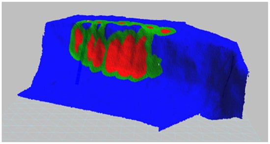
Figure 2.
Three-dimensional model of a free face from the terrain, green color when the burden value is close to the designed one, the blue color is larger burden deviations from the designed one, and red zones are smaller burden values than the designed one (O-Pitblast software distribution tool [19]).
Considering that the research was carried out to investigate the influence of burden deviation on the intensity of the blasting vibration, any major burden deviation, i.e., where the burden size is higher than the one set during drilling, was of particular importance. The laboratory model will show how these deviations affect the intensity of the blasting vibrations because the free face on the terrain can be irregularly shaped. Since the burden is not equal in all parts at the free face of the bench slope, as well as along the blasthole length, the surface of the blasted material is also taken into consideration. The surface of the blasted material, in this case, represents the surface at the cross-section of the blasthole, which is bordered by the free face and the blasthole, as shown in Figure 3.
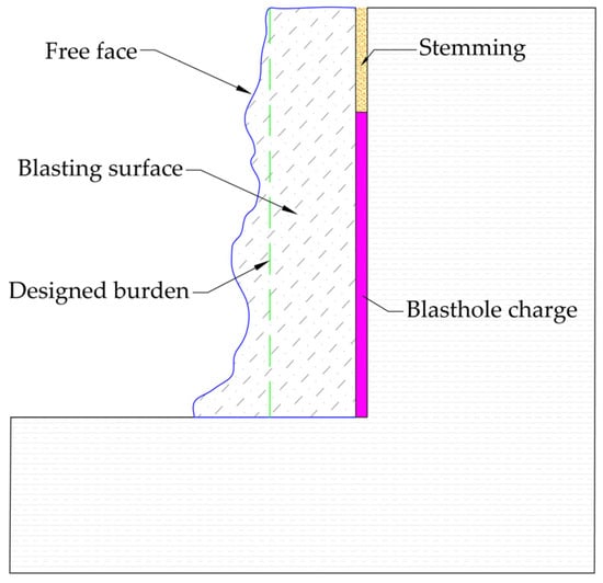
Figure 3.
The surface of the blasted material considered in this research.
Based on conclusions from previous research, the influence of increasing burden size on the increased intensity of blasting vibration can be taken into consideration. A larger burden size increases the rock volume to blast, which affects the burden movement as well as the increase in the intensity of the blasting vibration and burden movement [20]. Through the research presented in this paper, this dependence on the laboratory model through the investigation of a large number of repetitions of the blasting rounds and through testing the model on the field will try to be proven.
3. Methodology of Research
Working with the laboratory model, a similar procedure was carried out as would take place in the blast field, only of smaller dimensions, that is, in a block of homogeneous composition with established mechanical properties and instrumentally measured speeds of wave propagation through the material. For laboratory testing, a siporex block with dimensions of 250 × 600 × 250 mm was used. siporex blocks are used as artificial building materials produced from quality Portland cement and fine quartz sand [21]. The physical and mechanical characteristics of the siporex block are:
- Compressive strength 5 N/mm2;
- Volumetric mass 0.7 t/m3;
- Wave propagation speed 1900 m/s.
The procedure for measuring the speed of longitudinal and transverse waves through the material is shown in Figure 4. Measurements were made along the length, width, and height of the block.
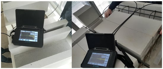
Figure 4.
Instrument and display used in the measurement with the speed of longitudinal waves on blocks.
During the measurement, an instrument from the Swiss manufacturer Proceq (Zurich, Switzerland), Pundit PL200 [22], was used to test and measure the speed of wave propagation through the siporex blocks. The technical specifications of the Proceq Pundit PL200 measuring instrument are shown in Table 1.

Table 1.
Technical specifications of the Proceq Pundit PL200 measuring instrument [23].
Proceq PL-Link software (version 3.0) [24] is used to export data from the instrument and display the measured values. Additionally, when exporting data, the software has an option for later reading the records from the instrument and data processing, which is shown in Figure 5.
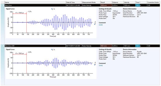
Figure 5.
Display of measured values of longitudinal waves with signal recording in Proceq PL-Link software, the blue line is the longitudinal wave through the material, and the red line is response time.
Vertical blastholes, 80 mm long and 8 mm in diameter, were drilled in the block. Small explosive charges were placed in each blasthole. The length of the stemming was 30 mm. Initiation was carried out with electric fuse heads—the primary ignition source used in electric detonators. One blasthole was initiated each time. Before each initiation, a photograph of the block, especially the free face, was taken in order to create a 3D model. The measuring point in relation to vibration was at a distance of 150 mm from the center of each blasthole.
After that, software processing was used to analyze the burden along each blasthole (per blasthole, there exists a pair of derived values of the burden, where the average is taken into consideration according to the percentage deviation from the designed one). Then, the burden values were input into the diagram, and then the comparative analysis of the results on the diagram was finalized. The burden values that are higher, equal and less than the designed ones were compared.
The measurement of vibration due to the initiation of each blasthole was measured using the Micromate instrument (Instantel, Ottawa, ON, Canada) [25]. The Micromate instrument is designed to monitor blasting vibration, sound/noise level, or air overpressure. The results from Micromate were exported and analyzed in specialized software, Thor [26], procured from the same company, and a measurement example is shown in Figure 6. The Micromate instrument is equipped with three channels for a triaxial geophone and one channel for an air overpressure or sound level microphone [27]. This instrument represents precise measurements of ground vibration (whether those ground vibrations are from blasting, pile driving, demolition, or similar artificially induced vibrations). With measured vibrations, this instrument provides the whole recorded waveform in three components (longitudinal, vertical, and transverse), with the possibility of analyzing PPV, frequency, peak acceleration, and peak displacement.
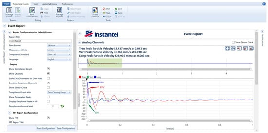
Figure 6.
Display of measured values of PPV for three components (longitude, blue colored; vertical, green colored; transverse, red colored) in Thor software (version 1.0.0.37).
In this case, Micromate was used to measure the peak particle velocity (PPV), an index used to measure blasting vibrations. PPV is also an important indicator for controlling the structural damage criteria [28]), such as blasting in open pit mines, and represents the maximum value in one waveform recorded time. The peak particle velocity (PPV) is one of the indicators of the intensity of vibrations in addition to the frequency of oscillation, which is measured by using seismographs during blasting in surface mines. It is specified in many standards used to assess the effects of vibrations on buildings, such as DIN 4150-3:1999 [29], as shown in Figure 7.
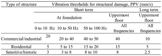
Figure 7.
Vibration guidelines for assessing the effects of vibrations on buildings [30].
Micromate was used to measure the particle velocity in three mutually perpendicular axes using triaxial sensors—geophones. The results of measurements represent longitudinal, transverse, and vertical components of blasting vibration. According to the DIN standard, the maximum of the three measured components is relevant and that is the peak particle velocity (PPV). The technical specifications of the Micromate Instantel measuring instrument are presented in Table 2.

Table 2.
Technical specifications of the Instantel Micromate measuring instrument [31].
The first test with the same laboratory model was carried out to show how the increase in burden size influences the increase in blasting vibration. Measurements of vibration were made at the burden size B = 20 mm, B = 30 mm, and B = 40 mm, with the same drilling angle of 90 degrees. One blasthole was initiated in the block, where multiple repetitions were performed for all three sizes of the burden for the same distance from the instrument for each case. With the initiation of the borehole, the instrument records all vibrations that appear in the block, and later, we analyzed that recorded waveform through specialized software Thor, where we can export data from it and read the PPV value; all of the data taken from the instrument are shown in tables in Section 4. Before each initiation, a 3D model of the laboratory model was created in order to obtain the most accurate data for analysis. The 3D model is created by using a photograph of a laboratory model, which is taken before every initiation and using photogrammetry to stitch them together and create a model in O-Pitblast.
The initiations were carried out first for the value of the burden B = 20 mm. For this case, several measurements with the designed burden size and with deviations in burden size were performed. Then, the burden was increased to B = 30 mm, where several measurements for the designed burden or at least approximately designed were carried out. Each subsequent firing in the block leaves some kind of irregular free face, where the one with the largest deviation was used as a benchmark for deviation analysis, which is shown in tables as the surface of the blasted material parameter. The next is B = 40 mm, where the same test was repeated as in the previous steps. Each movement was followed by re-setting the instrument to the same distance of r = 150 mm before each initiation of the blasthole. The dimensions of the block, and the position of the instrument in relation to the blasthole, where the instrument was moved by the same distance for each subsequent shot, are shown in Figure 8.
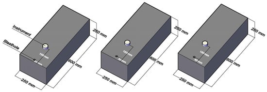
Figure 8.
Model of blocks for different burden values with the positions of the measuring points.
For all three cases, the burden size is shown, where multiple measurements were performed, i.e., initiation at three different values of the burden size, both in the designed conditions for each of them, as well as for those cases where there were deviations of burden size.
This test was carried out to show how the designed burden for three cases, and all have some small deviations, which can be seen in the diagrams later in this text. Increasing the burden size from B = 20 mm to B = 30 mm and B = 40 mm, the surface of blasted material increased and affected blasting vibration.
The second test was carried out on the same type of block to show how burden deviations influence the increase in blasting vibration. As in the previous test, initiation was performed for the value of burden B = 30 mm, but the additional initiation was carried out in the case when the burden is equal to designed one and in the cases when there are burden deviations.
The deviations observed that are of interest for analysis are those that represent the higher burden values than the designed ones because, based on previous research, increased burden size increases vibrations. Deviations are examined in relation to the surface of the blasted material, the information of which we obtained from the software, as shown in Figure 9.
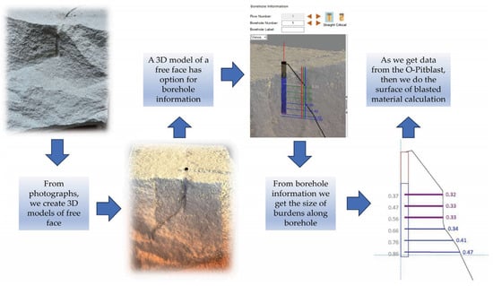
Figure 9.
The process of obtaining surface of blasted material data from the model using O-Pitblast software.
Theoretically, all bumps on the free face of the block that are above the value of the design burden affect the intensity of the vibration. A detailed view of the free face, which has an irregular shape, i.e., the front of the slope and its influence on the burden values, are shown in Figure 10.
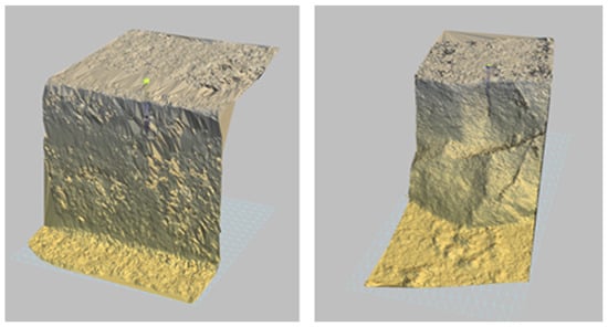
Figure 10.
Three-dimensional model of the sample before and after initiation of the blasthole in O-Pitblast software.
Deviations in burden that are greater than the designed burden value should affect the increase in vibrations. The increase in burden automatically affects the increase in the rock volume per blasthole as well as the intensity of blasting vibrations.
The positions of the instruments during the measurement of blasting vibration are given, and the condition of the free face before and after initiation is shown in Figure 11.
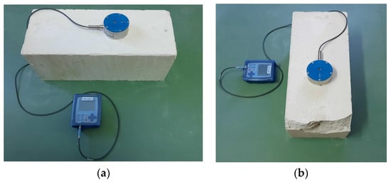
Figure 11.
Measurement of vibrations and condition of the free face before (a) and after (b) the initiation of blasthole.
4. Results
After the tests were carried out for these burden values of B = 20 mm, B = 30 mm, and B = 40 mm, 27 measurements were taken in order to determine the dependence of the increase in burden value, which at the same time affects the increase in the surface of the blasted material, on the increase in the intensity of vibration. All results of the measurement are shown in Table 3.

Table 3.
Test results of measurement burden influence for B = 20 mm, B = 30 mm, and B = 40 mm.
The test results for three burden values were statistically analyzed. Figure 12 shows the dependence of PPV on the surface of the blasted material for different burden values.
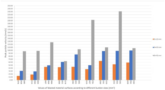
Figure 12.
Dependence of the peak particle velocity (PPV) on the blasted material for different burden values.
Further research was carried out to examine the case where the burden was, for example, designed so that B = 30 mm along the entire length of the blasthole. Then, it could be said that these were optimal conditions that affect the intensity of vibrations in regard to the burden that has deviations from the designed one, i.e., is not equal along the entire blasthole. The dependence of peak particle velocity (PPV) on the burden deviation from the designed one is presented in Figure 13.
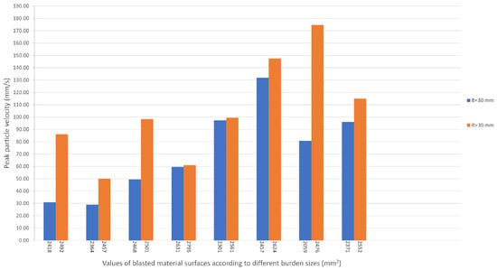
Figure 13.
Dependence of peak particle velocity (PPV) in relation to the deviation value of the burden size from the designed one.
According to the diagram given in Figure 13, it can be seen that the values of the vibrations due to the initiation of the blastholes increase with the increase in the surface of the blasted material. For this test, the measurements are shown in Table 4.

Table 4.
Test results of measurement burden influence for B = 30 mm and B > 30 mm.
To determine the dependence of increased vibrations on burden deviation more precisely, the measured results will also be analyzed mathematically. In this case, the dependence could be:
where
- represents the ratio between peak particle velocity (PPV) for the burden size B = 30 mm and B > 30 mm;
- represents the ratio between the surface with the deviation of the burden size for the values B = 30 mm and B > 30 mm.
Using data from the diagram presented in Figure 10, the surface formed in relation to the designed burden and the deviation values of the burden for each measurement can be taken into account. The difference between these surfaces can be calculated using the following equation:
where
- is the surface with designed burden size (mm2);
- is the surface with burden deviation from the designed one (mm2).
The surface of the blasted material for the case when the burden does not have deviations and it is equal to the designed one , can be calculated as the sum of the surface of the blasted material of each blasthole, as given in Equation (3). In the same way, the surface of the blasted material for the case when there is a deviation of the burden and when its value is greater than the designed one , can be obtained, as shown in Equation (4).
and
By inserting the obtained values into Equation (2), the value of can be calculated as follows:
Using a similar procedure, the values of the peak particle velocity (PPV) for each repetition for the values of B = 30 mm and B > 30 mm can be calculated. The value of variable represents the difference in the peak particle velocity (PPV) of the designed burden and the burden with deviations for the burden values of B = 30 mm and B > 30 mm, respectively.
where
- represents the peak particle velocity (PPV) measured for B = 30 mm (mm/s);
- represents the peak particle velocity (PPV) measured for B > 30 mm (mm/s).
The values of and can be calculated in the same way as shown in Equations (3) and (4). The calculation for both values is represented through the following equations for each testing case.
and
The obtained values for and are inserted in Equation (5), and the value of is calculated as follows.
Additionally, the coefficient from Equation (1) for each of the measured values can be calculated and shown on the diagram to represent the dependence of peak particle velocity (PPV) on the values of the burden deviations.
5. Model Verification on the Blast Field
Based on tests on the laboratory model and the obtained results, as well as the analysis of the results, the verification of the model in terms of the influence of the burden deviation on the intensity of the vibration during blasting was carried out on the blast field. For this case of testing at a quarry, 12 blastholes were used. The same instrument and methodology were used to measure the blasting vibration during field tests. The instrument was placed at a distance of 60 m from the axis of the blasthole. The diameter of the blasthole was 89 mm, and the blasthole length was 10 m. In this case, an example of a blasthole profile with different values of the burden along the length of the blasthole was given. These values were used in the calculation of the surfaces, as in the case of the laboratory model.
Figure 14 represents a 3D model of the blasthole with different values of the burden where the burden size is less than the designed one (red line), equal to the designed one (green line) and greater than the designed one (blue line). In this case, through comparative analysis of the results of measurements on the laboratory model and field measurements, in places where there is a deviation of burden greater than the designed one (blue line), the value of peak particle velocity should be higher. The different values of burden along the blasthole are also represented with a number of each value for the burden deviation from the designed one.
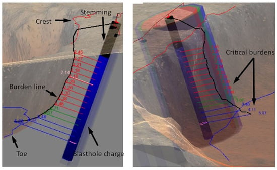
Figure 14.
Three-dimensional model of the blasthole obtained using O-Pitblast software with the display of different values of the burden.
The records of the vibration instruments and the results of statistical analysis confirm the increase in the intensity of blasting vibration as the value of burden is higher (as shown in the graph in Figure 14). All measurement blasting vibrations from the field tests shown in the Figure 15, are represented in Table 5.
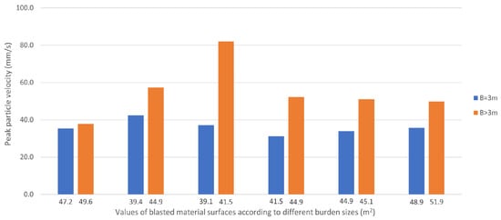
Figure 15.
Dependence of peak particle velocity (PPV) in relation to the value of the deviation of the burden size from the designed one during the test on the blast field.

Table 5.
Test results of measurement from field test with burden influence for B = 30 mm and B > 30 mm.
Verification of the model obtained under laboratory conditions was performed by applying the same formulas to the data obtained from measurements in the field. The surface of the blasted material for the case, when the burden is equal to the designed one, can be calculated using Equation (3):
The surface of the blasted material for the case when there is a deviation in the burden and when its value is greater than the designed one can be obtained using Equation (4):
The difference between these surfaces “∆P” can be calculated using Equation (2):
Calculation of the peak particle velocity (PPV) when the burden value is equal to the designed one can be calculated using Equation (6):
Calculation of the peak particle velocity (PPV) when the burden is equal to the designed one using Equation (7):
The ratio between the peak particle velocity (PPV) at the deviation of the burden with deviations is calculated using Formula (5):
Additionally, the coefficient from Equation (1) for each of the measured values can be calculated, and this is shown on the diagram to represent the dependence of peak particle velocity on the burden deviation values.
6. Discussion
The diagram shown in Figure 12 and Table 4 shows that the values of the vibrations due to the initiation of the blastholes increase with the increase in the surface of the blasted material.
Based on this, more precise data were obtained in terms of the dependence of the burden size analyzed by examining the surface of the blasted material for the case where the burden value is B = 20 mm. Due to irregularities at the free face, the dependence of the burden size is here expressed through the surface of the blasted material, where it is different from blasthole to blasthole. Other data were obtained for the other two cases where burden values were B = 30 mm and B = 40 mm. Therefore, based on the analyzed data, it can be concluded that the largest intensity of vibration is for the designed burden of 40 mm.
In most cases, the value of the burden varies and is not equal to the designed one along the entire length of the blasthole on the blast field. Burden deviation is determined using O-Pitblast software, which can provide all distances of the burden to the free surface along the borehole at the default range, and then we can calculate the surface of the blasted material. That is why, in these tests, the dependence of the burden size on the intensity of the vibration was analyzed by analyzing the surface of blasted material because the value of the burden directly affects the size of the surface of the blasted material.
In order to obtain the dependence of peak particle velocity (PPV) in relation to the burden deviation from the designed one for the second test for B = 30 mm, 16 measurements were performed through laboratory tests. Measurements were first taken when the burden value was equal to the designed one along the entire length of the blasthole, and then for the case where deviations were higher than the designed ones. Through this model, all of the burden values higher than the designed ones were of interest in terms of analysis because they affected the increase in vibrations, according to previous research.
Based on the tests of the laboratory model and the obtained results, as well as the analysis of the results, the verification of the model of the influence of burden deviation on the intensity of the vibration during blasting was carried out in the blast field. For this case of testing on a quarry, 12 blastholes were used. In the end, a comparative analysis of the results obtained from laboratory tests and field testing was performed.
7. Conclusions
The obtained model represents the results of the research in order to examine the influence of burden deviation from the designed one on the intensity of the blasting vibrations through laboratory and field measurements. During laboratory testing, a large number of measurements were carried out for two different conditions: when the burden size is equal to the designed one and when there is burden deviation.
Blasting vibration caused by the initiation of blastholes was monitored through the use of blasting seismographs placed at precisely determined distances from the blastholes. The obtained results from the laboratory measurements enabled a comparison of the values of burden and the values of the peak particle velocity, the basic parameters of the intensity of blasting vibration, for the cases with and without burden deviation.
The statistical analysis of the measured data and the obtained diagrams clearly show the difference in the values of the peak particle velocity when there are larger values of burden deviation and for the case when the value of burden deviation is lower, i.e., when the burden is close to the designed one. Because the value of the burden size is variable along the length of the blasthole, the results were mathematically analyzed by examining the ratio of the peak particle velocity and the surface of the blasted material, which was taken for observation.
The model obtained from laboratory testing was verified under real conditions in the blast field. The blastholes were initiated under different conditions of burden size while the peak particle velocity was monitored. The basic parameter of the model, coefficient K, which represents the ratio of the peak particle velocity and the surfaces of the blasted material from laboratory and field testing, indicates that there is a connection between these values, which can be seen through the results of the calculation. The deviation of coefficient K, as obtained from laboratory and field measurements, was 5.5%.
The results of the measurements under laboratory conditions, especially in the field, depend largely on the characteristics of the material in which the tests are carried out. The presence of interlayers, cracks, and fissures in the rock material can have a significant impact on the effect of blasting and, thus, the intensity of the blasting vibration.
The research presented in this paper was an attempt to find a direct dependence between the deviation in burden and blasting vibration, as well as the influence of increased burden deviation on the intensity of the blasting vibration. Since blasting vibration does not depend on just one blasting parameter, such as burden, it is necessary to carry out further research to improve the model in relation to other blasting conditions.
From this laboratory model and terrain test, a numerical model can be designed in later research, which could maybe provide some predictions in terms of the blast vibration caused by burden deviation. This research can also be used to reduce factors such as blast vibration, fly rock, boulders, etc., as well as improve safety during blasting and environmental protection.
Author Contributions
Conceptualization, S.M.; methodology, S.M. and L.K.; software, S.M.; validation, M.N., N.S., J.M. and N.Đ.; formal analysis, S.M. and L.K.; investigation, S.M., L.K., M.N., N.S., J.M. and N.Đ.; resources, S.M., L.K. and M.N.; data curation, M.N., N.S., J.M. and N.Đ.; writing, original draft preparation, S.M.; writing, review and editing, L.K. and M.N.; visualization, N.S., J.M. and N.Đ.; supervision, L.K. and M.N. All authors have read and agreed to the published version of the manuscript.
Funding
This research received no external funding.
Data Availability Statement
Data is contained within the article.
Acknowledgments
The author would like to thank the Serbian Ministry of Education, Science, and Technological Development for their support of the Project of Technological Development for TR33003.
Conflicts of Interest
The authors declare no conflict of interest.
References
- Simangunsong, G.M.; Maehara, S.; Shimada, H.; Kubota, S.; Wada, Y.; Ogata, Y. Vibration and fragmentation by changing the blast burden at Funeo limestone quarry. Sci. Technol. Energetic Mater. 2006, 67, 102–110. [Google Scholar]
- Singh, D.P.; Sastry, V.R. An investigation into the effect of blast geometry on rock fragmentation. In Proceedings of the 6th ISRM congress, Montreal, QC, Canada, 30 August–4 September 1987; pp. 721–725. [Google Scholar]
- Singh, D.P.; Sastry, V.R.; Suresh, C.V. Fragmentation in Jointed Rock Material-A Model Scale Investigation; National Seminar, Indigenous Development of Mining Explosives and Accessories, Policies and Programme: New Delhi, India, 1985. [Google Scholar]
- Uysal, O.; Arpaz, E.; Berber, M. Studies on the effect of burden width on blast-induced vibration in open-pit mines. Environ. Geol. 2007, 53, 643–650. [Google Scholar] [CrossRef]
- Choudhary, B.S.; Arora, R. Influence of front row burden on fragmentation, muckpile shape, excavator cycle time, and back break in surface limestone mines. Iran. J. Earth Sci. 2018, 10, 1–10. [Google Scholar]
- Konya, C.J. Blast Design; Intercontinental Development Corporation: Montville, OH, USA, 1995. [Google Scholar]
- Jenkins, S.S. Adjusting blast design for best results. In Pit and Quarry; Balkema: Rotterdam, The Netherlands, 1981. [Google Scholar]
- Konya, C.J. Rock Blasting and over Break Control, 2nd ed.; National Highway Institute: Arlington, VA, USA, 2003. [Google Scholar]
- Lu, W.; Leng, Z.; Hu, H.; Chen, M.; Wang, G. Experimental and numerical investigation of the effect blast-generated free surfaces on blasting vibration. Eur. J. Environ. Civ. Eng. 2018, 22, 1374–1398. [Google Scholar] [CrossRef]
- Prasad, S.; Choudhary, B.S.; Mishra, A.K. Effect of stemming to burden ratio and powder factor on blast-induced rock fragmentation-a case study. IOP Conf. Ser. Mater. Sci. Eng. 2017, 225, 012191. [Google Scholar] [CrossRef]
- Mortazavi, A.; Katsabanis, P.D. Modeling burden size and strata dip effects on the surface blasting process. Int. J. Rock Mech. Min. Sci. 2001, 38, 481–498. [Google Scholar] [CrossRef]
- Dumakor-Dupey, N.K.; Arya, S.; Jha, A. Advances in Blast-Induced Impact Prediction-A Review of Machine Learning. Minerals 2021, 11, 601. [Google Scholar] [CrossRef]
- Armaghadi, D.J.; Hajihassani, M.; Mohamad, E.T.; Marto, A.; Noorani, S.A. Blasting-induced flyrock and ground vibration prediction through an expert artificial neural network based on particle swarm optimization. Saudi Soc. Geosci. 2013, 7, 5383–5396. [Google Scholar]
- Erten, O.; Konak, G.; Kizil, M.S.; Onur, A.H.; Karakus, D. Analysis of quarry-blast-induced ground vibrations to mitigate their adverse effects on nearby structures. Int. J. Min. Miner. Eng. 2009, 1, 313. [Google Scholar] [CrossRef]
- Iphar, M.; Yavuz, M.; Ak, H. Prediction of ground vibration resulting from the blasting operations in an open-pit mine by adaptive neuro-fuzzy inference system. Environ. Geol. 2008, 56, 97–107. [Google Scholar] [CrossRef]
- Bamford, T.; Esmaeili, K.; Schoellig, A.P. A real-time analysis of rock fragmentation using UAV technology. Int. J. Min. Reclam. Environ. 2017, 31, 439–456. [Google Scholar] [CrossRef]
- Pitblast-Rethinking the Drill & Blast Industry. Available online: https://www.o-pitblast.com/ (accessed on 4 October 2023).
- Zang, Z.X.; Chi, L.Y.; Yi, C. An empirical approach for predicting burden velocities in rock blasting. J. Rock Mech. Geotech. Eng. 2021, 13, 767–773. [Google Scholar] [CrossRef]
- Pitblast-Distribution Tool. Available online: https://downloads.o-pitblast.com/files/manual/O-Pitblast%20Manual%202021.pdf (accessed on 9 November 2023).
- Wimmer, M.; Nordqvist, A.; Ouchterlony, F.; Nyberg, U.; Furtney, J.K. Burden movement in confined drift wall blasting tests studied at the LKAB Kiruna SLC mine. In Rock Fragmentation by Blasting; Singh, P.K., Sinha, A., Eds.; Taylor & Francis Group: London, UK, 2013; pp. 373–383. [Google Scholar]
- Bogunovic, D.; Kecojevic, V. Artificial screen for reducing seismic vibration generated by blasting. Environ. Earth Sci. 2007, 53, 517–525. [Google Scholar] [CrossRef]
- Pundit 200|Ultrasonic Pulse Velocity Test of Concrete. Available online: https://www.screeningeagle.com/en/products/pundit-200 (accessed on 4 October 2023).
- Pundit 200|Ultrasonic Pulse Velocity Test of Concrete. Available online: https://www.screeningeagle.com/en/sales-flyers/SF-pundit-200 (accessed on 4 October 2023).
- Pundit 200|Ultrasonic Pulse Velocity Test of Concrete. Available online: https://media.screeningeagle.com/asset/Downloads/Pundit%202_Operating%20Instructions_English.pdf (accessed on 4 October 2023).
- Instantel|Instantel Products. Available online: https://www.instantel.com/products (accessed on 4 October 2023).
- Thor|Instantel. Available online: https://www.instantel.com/products/thor (accessed on 12 November 2023).
- Sensors & Accessories|Instantel. Available online: https://www.instantel.com/sites/instantel.com/files/media/2022-11/M7063%20Micromate%20and%20Minimate%20Pro%20Microphones-Rev%2003.pdf (accessed on 4 October 2023).
- Faradonbeh, R.S.; Armaghani, D.J.; Abd Majid, M.Z.; Tahir, M.M.; Murlidhar, B.R.; Monjezi, M.; Wong, H.M. Prediction of ground vibration due to quarry blasting based on gene expression programming: A new model for peak particle velocity prediction. Int. J. Environ. Sci. Technol. 2016, 13, 1453–1464. [Google Scholar] [CrossRef]
- DIN 4150-3; Structural Vibration Part 3: Effects of Vibration on Structures. German Institute for Standardisation: Berlin, Germany, 1999.
- Nguyen, L.; Chan, N.B. Designing an Ardunio-microprocessor-and-Labview-based system for monitoring wave spread in the ground caused by constructing activies. MATEC Web Conf. 2017, 138, 04003. [Google Scholar]
- Micromate|Instantel. Available online: https://www.instantel.com/products/micromate (accessed on 4 October 2023).
- Safety Requirements for Electrical Equipment for Measurement, Control, and Laboratory Use—Part 1: General Requirements. International Electronical Commission: Geneva, Switzerland. Available online: https://webstore.iec.ch/publication/4279#additionalinfo (accessed on 20 November 2023).
Disclaimer/Publisher’s Note: The statements, opinions and data contained in all publications are solely those of the individual author(s) and contributor(s) and not of MDPI and/or the editor(s). MDPI and/or the editor(s) disclaim responsibility for any injury to people or property resulting from any ideas, methods, instructions or products referred to in the content. |
© 2023 by the authors. Licensee MDPI, Basel, Switzerland. This article is an open access article distributed under the terms and conditions of the Creative Commons Attribution (CC BY) license (https://creativecommons.org/licenses/by/4.0/).