Article

Numerical Study of Endwall Modification with Micro-Scale Ribs in a Turbine Cascade

School of Energy and Power Engineering, Xi’an Jiaotong University, Xi’an 710049, China
*
Author to whom correspondence should be addressed.
Appl. Sci. 2023, 13(23), 12594; https://doi.org/10.3390/app132312594
Submission received: 6 November 2023 / Revised: 18 November 2023 / Accepted: 20 November 2023 / Published: 22 November 2023

Abstract

:
A novel modification method, the ‘micro-scale’ rib, is proposed to expand cooling coverage for turbine endwalls. However, the introduction of the rib will inevitably affect the flow in the near-wall region. Therefore, the variation in the flow pattern for the traditional model of secondary flow needs further exploration. In this paper, to gain a clearer understanding of the micro-scale rib, the original endwall and three types of ribbed endwalls were adopted to numerically present the detailed flow, film cooling, and heat transfer information for the endwall surface and phantom cooling on the suction side (SS) of the blade. The Ansys code CFX was utilized to solve the 3D Reynolds-averaged Navier–Stokes (RANS) equations, and the SST k-ω was selected as the turbulence model after the verification. The results show that the rib-like vortex changed the flow of the coolant and had various impacts on the cooling characteristics. Although the cooling performance of the ribbed endwall improved, it also had a negative impact on heat transfer in most cases. Compared with the original, the vertical rib cases provided optimal film cooling, with increases of 26.9% and 17.4% for rib spacing values of 8 mm and 10 mm, respectively, with little difference in heat transfer (less than 1%). In addition, the horizontal rib cases presented the worse performance for both film cooling and heat transfer, which indicates that the rib layout should consider a mainstream flow direction for future designs.

1. Introduction

For modern gas turbines, the cascade faces increasing thermal loads. These thermal loads are affected by many factors: cascade geometry, mainstream conditions, and so on. To prevent the harm from thermal loads, film cooling was used to protect the turbine cascade. In addition, due to the installation of the blade, there is an upstream slot and a slashface on the endwall surface. The coolant will flow out of these gaps and cool the endwall.
Early research carried out by Pasinato et al. [1] indicated that it was feasible for a numerical calculation to simulate the flow in turbine cascades with the correct turbulence model and numerical setup. Lynch and Thole [2] studied the leakage from a combustor–turbine gap and presented a pattern of cooling effectiveness ( η ). Oke et al. [3] thought that the cross-flow led the coolant to the suction side (SS). Mahmood and Acharya [4] measured the heat transfer of the endwall with the modification of the leading edge (LE) and the endwall. Li et al. [5] experimentally studied film and impingement cooling on the endwall. Their results showed that film cooling was affected by the passage vortex (PV), thus improving the cooling performance of the endwall, close to the SS. Choi et al. [6] carried out experimental and numerical research on an endwall with a first-stage blade in a turbine cascade. They found that the heat transfer of the endwall corresponded to the distribution of secondary flows. Xu et al. [7] carried out a numerical study on the upstream interrupted slot and found that the blowing ratio and the distance between the LE of the blade and the slot-affected η .
Phantom cooling research has increased in recent years. An experimental investigation was carried out by Zhang et al. [8], and they found that the coolant from blades could cool the endwall surface using a proper compound angle. Similarly, Yang et al. [9] carried out a numerical investigation on the phantom cooling of an endwall with the coolant from the LE of a blade. In addition, Zhang et al. [10] experimentally studied the effect of the coolant from the endwall on the phantom cooling of the blades, and the results showed the cooling coverage on the SS roots.
Chen et al. [11] carried out a sensitivity analysis on a non-axisymmetric endwall and analyzed which position most affected the aerodynamic characteristics for passage. Chen et al. [12] numerically studied the effects of a cooling jet in a special position to counter the horseshoe vortex of an LE leg. Burdett et al. [13] carried out experimental research on a contour endwall with upstream holes. The results showed that the negative effect of the PV on cooling could be inhibited when the mass flow ratio (MFR) of the upstream coolant was more than 0.75%. Zhang et al. [14] carried out an investigation of film holes and the mid-passage gap (MPG) on a turbine endwall, using experimental and numerical methods. They found that the leakage from the MPG demonstrated little impact on the coolant from upstream film holes. Yang et al. [15] also studied film cooling patterns with upstream leakage and found that it benefited the film cooling from the film holes. Wang et al. [16] numerically studied lobe-shaped holes using a large eddy simulation (LES) to track the flow field of film cooling. Zhao et al. [17] used the response surface method to analyze the cooling characteristics of a stream-cooled blade.
There are complex secondary flows in the cascade that affect aerodynamic, cooling, and heat transfer characteristics. In recent years, a novel endwall modification, the micro-scale rib, was proposed to improve the flow in the cascade. Wang et al. [18] considered incidence effects on an endwall with micro-scale ribs. The results showed that the ribs effectively weakened the intensity of the horseshoe vortex and PV and thus enhanced the cooling performance. Yang et al. [19] numerically studied small-scale structures, which are the ribs, on the endwall. They found that the cooling characteristic of the endwall could be effectively improved by the small-scale structures. Du et al. [20] carried out a numerical investigation on the flow and cooling characteristics of a micro-ribbed vane endwall. Their findings indicated that coolant migration was inhibited by the ribs and benefited the lateral coverage of the coolant. In addition, another endwall modification was carried out by Shote et al. [21], indicating that the filleted passage performed better than the original case with respect to aerodynamic and cooling performance.
So far, several methods for endwall modification have been proposed, aiming to enhance certain characteristics. Further information about the benefits and demerits of endwall modification is listed in Table 1. As highlighted from the above studies, endwall modifications have been investigated by researchers, but most of them only focused on several aspects instead of a comprehensive evaluation of a micro-scale rib on an endwall. Therefore, to gain a comprehensive understanding of the effect of micro-scale ribs on film cooling (including phantom cooling), heat transfer, and aerodynamic characteristics, original and ribbed endwalls are studied with upstream leakage and various rib types and rib spacings in this paper. A detailed flow pattern for the endwall and ribs is given. This paper is expected to provide extensive modification advice for the cooling design of turbine endwalls.

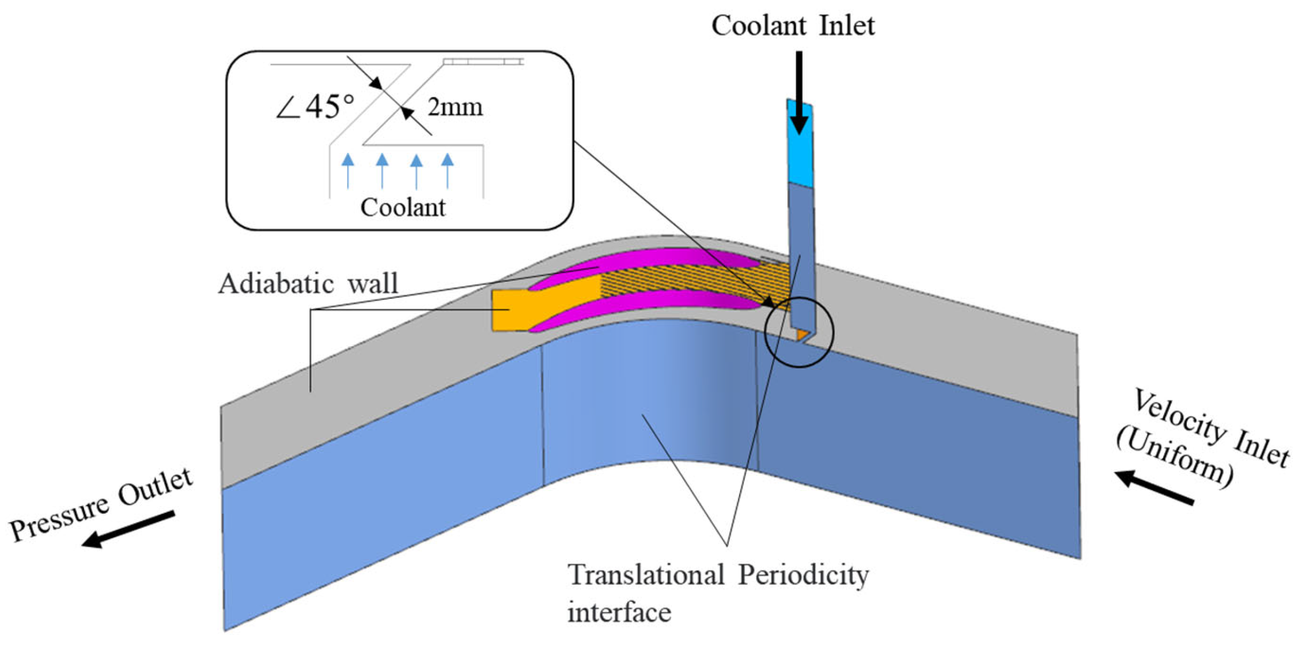
2. Computational Methods

The ribbed endwall was adopted as the computational model. Its profile originated from the geometry of turbine cascade. Its detailed geometry is shown in Figure 1. The mainstream was at a zero-attack angle to the LE of blade. In this paper, the original endwall and three types of ribbed endwall were studied and their schematics are shown in Figure 2. The value of h (rib height) was 0.5 mm, while the values of s (rib spacing) were 8 mm and 10 mm.
Figure 3 shows the numerical model of ribbed endwall for upstream slot leakage. The numerical model of cascade channel refers to the experimental facilities, which indicated that the sizes of the cascade channel and micro-scale rib were consistent with the experimental conditions. The detailed information of experimental facilities and the measurement method is the same as in the literature [14]. When simulating the cooling characteristics of the upstream slot for the ribbed endwall, the double sides of the passage were given as periodic boundary conditions, and the remaining walls were given as adiabatic non-slip walls. The mainstream inlet was given as velocity boundary, the mainstream outlet was given as pressure outlet, and the coolant inlet was given as mass flow inlet.
RANS equation was solved using the commercial software CFX 19.0. The turbulence term was discretized with high resolution and the RMS residual was less than 10−5 to assume convergence. To meet the actual requirement of density ratio, CO2 was used for coolant and the air was used for mainstream. The solved governing equations are shown in Equations (1)–(3).
Continuity equation:
ρ t + · ρ U = 0
where ρ represents the fluid density and U represents the velocity vector of fluid.
Momentum equation:
ρ u t + ρ u · u = ρ f + ·
where f and represent the mass force and surface force acting on the fluid surface, respectively.
Energy equation:
ρ h t ρ t + ρ U h = λ T + U τ + U S M + S E
where h represents the total specific enthalpy; U τ represents the work of viscosity force; U S M represents the work of external force; S E represents the source item of energy.

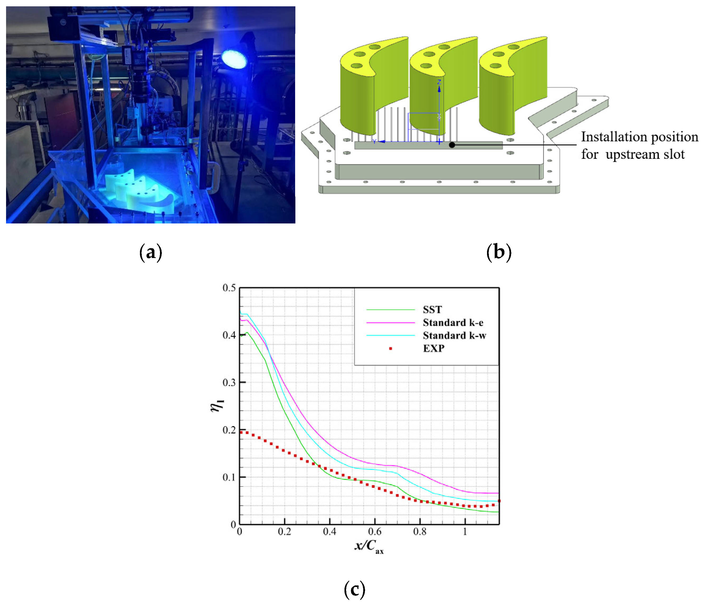
2.1. Verification of Turbulence Model

In this section, SST k-ω, standard k-ω, and standard k-ε were chosen for the comparison of turbulence models under the condition of MFR = 1%. A test article of ribbed endwall was adopted to conduct verification and the experimental condition coincided with the boundary condition of numerical calculation. The comparison result is shown in Figure 4. In the experimental contrast, pressure-sensitive paint (PSP), which is widely used in turbine cooling research, was adopted to measure the η of endwall. The difference between the experiment and numerical calculation was focused on the upstream slot, which means that the boundary condition of two sides of passage was set as translational periodicity for coolant chamber wall, which made a difference of η at the vicinity of upstream slot outlet. In general, the numerical tendency of η l coincided with the experiment. Although all the turbulence models overpredicted the η l in the front range of x/Cax, the SST coincided with the experiment in most x/Cax (>0.3). Therefore, SST was selected for the following calculations.

2.2. Mesh Generation and Grid Independence Analysis

Due to the rib, the grid of the ribbed endwall needs local mesh encryption to simulate the near-wall flow. The detailed mesh topology is shown in Figure 5. The grid was generated using Pointwise. To meet the requirement of turbulence model, the first layer height of boundary layer was 0.001 mm and thus y+ was defined as less than 1, which is suitable for SST k-ω.
The sensitivity analysis of grid was conducted using the GCI [22]. Three types of grids (coarse with 23,989,236 cells, moderate with 35,531,716 cells, and fine with 66,834,042 cells) were adopted. Details of GCI are presented in Table 2. The area-averaged η was selected as target variable. After the calculation, the extrapolation value was 0.155815, which presented the deviation values of 0.14% and 1.93% for fine grid and moderate grid, respectively. The GCI value of fine and moderate grid was 0.18% and 3.17%, respectively, indicating that these two grids could be used for calculation. However, the number of grids in the ribbed endwalls was relatively high. Therefore, to balance the computational accuracy and the time costs, the moderate grid was adopted for the following calculation, which was suitable.

3. Results and Discussions

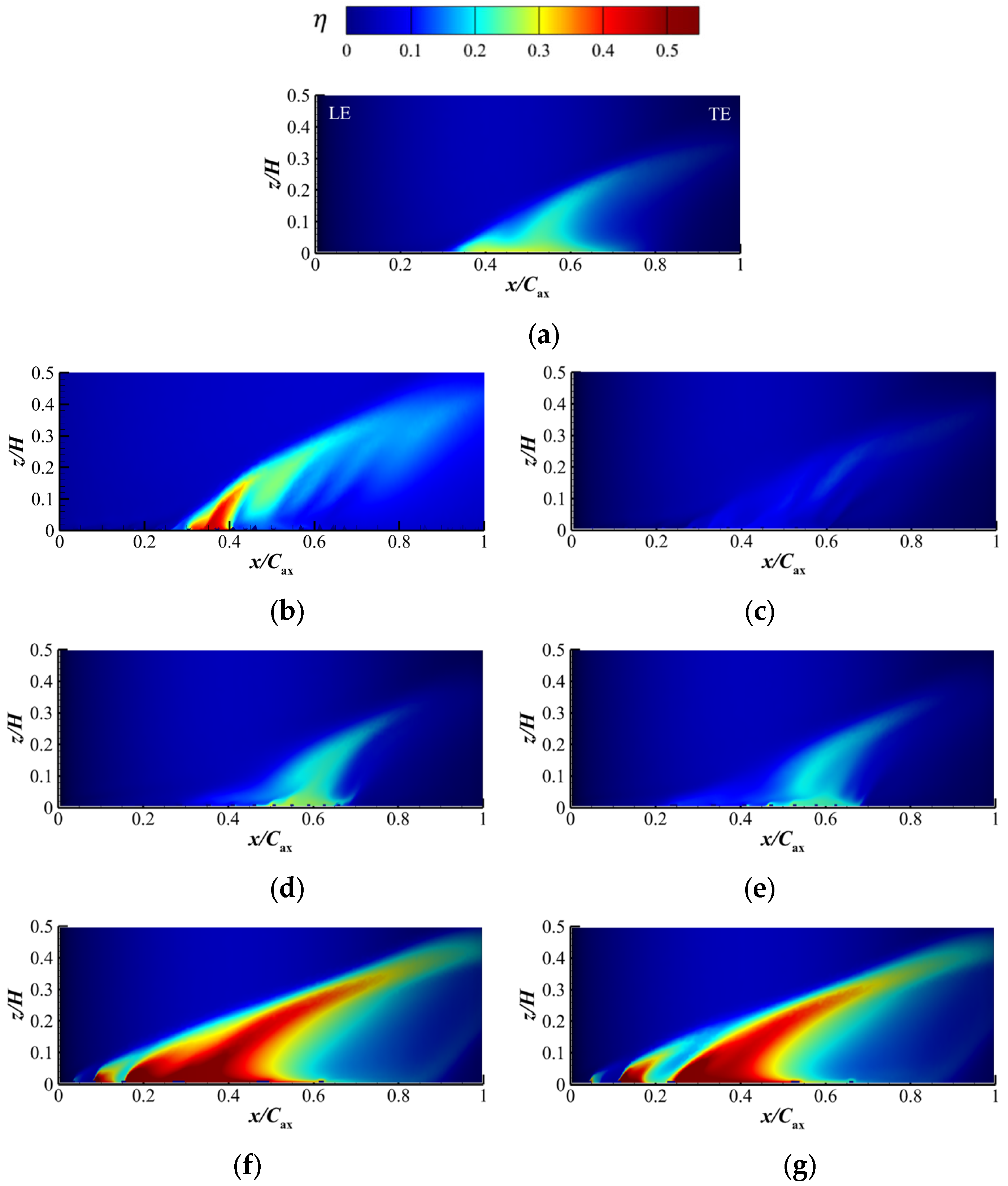
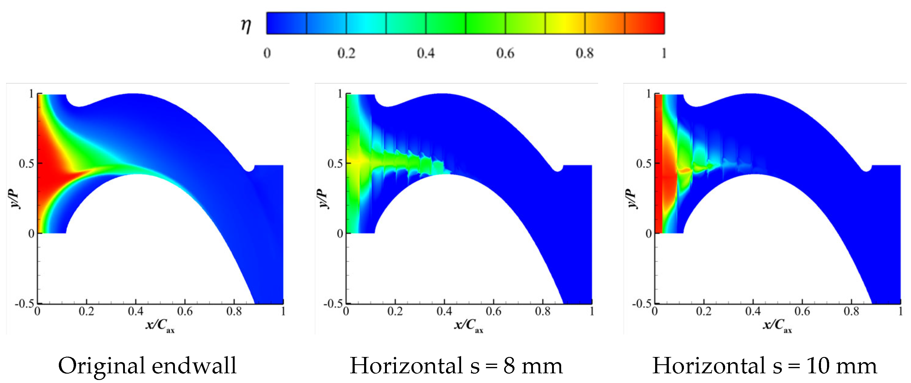
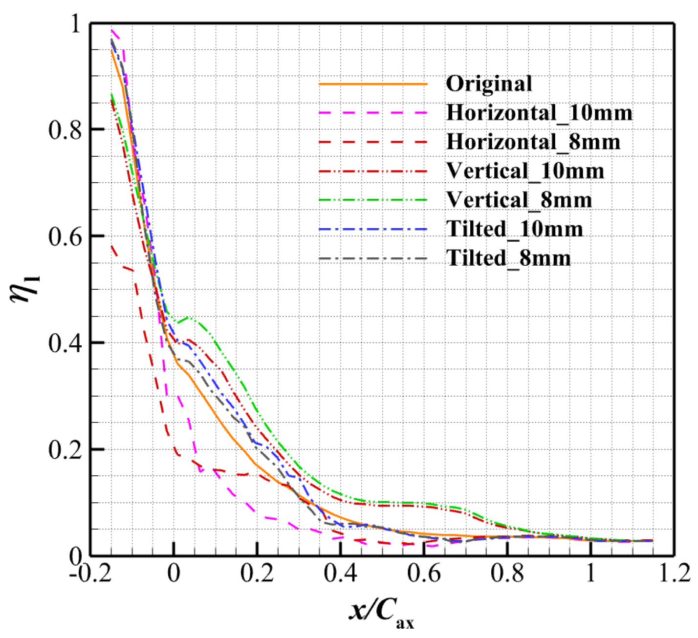
3.1. Film Cooling Characteristic

In reality, due to the existence of the micro-scale rib, the coolant could flow along the rib geometry. In this section, four types of endwalls (original, horizontal rib, tilted rib, and vertical tib) were numerically studied. Boundary conditions are shown in Table 3. The Reynolds number (Re) of the mainstream was 326,000, which corresponds to the Um value, 40 m/s.
The definition of η can be expressed as Equation (4).
η = T m , i n T a w T m , i n T c , i n
where T m , i n represents the temperature of the mainstream inlet, T a w is the adiabatic wall temperature, and T c , i n is the temperature of the coolant.
The numerical results of the cooling characteristics of the horizontal rib are presented in Figure 6. With a fixed end position of the ribs (0.57 Cax) and rib spacing, the initial rib position of the horizontal ribs (with a rib spacing value of 8 mm) is located at the outlet of the upstream slot. So, the coolant first flows through the rib surface and then through the endwall surface. As a result, there is a significant resistance on the endwall cooling, and the cooling magnitude and the coverage area rapidly diminish. The coolant dissipates at about 0.4 x/Cax. For the horizontal ribs with a rib spacing of 10 mm, there is a short distance from the outlet of the upstream slot to the initial rib position, so it exhibits high cooling effectiveness in the circumferential direction. After that, η decreases rapidly, and the coverage of the coolant in the axial direction is not as good as that of the case of 8 mm horizontal ribs. The direction of horizontal ribs is similar to the flow direction of the PV in general, and the coolant coverage resembles it on the smooth endwall. However, in the axial direction, due to the restriction by ribs, the circumferential coverage of the coolant is apparently reduced.
The numerical results of the cooling characteristics of the tilted rib are presented in Figure 7. The tilted ribs guide the coolant toward the PS, and since the direction of the endwall’s secondary flow is roughly opposite to the direction of the ribs in this case, the η transition is relatively abrupt at 0.3–0.4 x/Cax (red circle in Figure 7). Also, the guiding effect of the ribs improves the cooling effectiveness of the leading edge near the SS, but inhibits the cooling effectiveness in the corner of the SS and blade. In addition, there is no significant difference in the endwall cooling effectiveness contour for tilted ribs with different rib spacings.
The coolant coverage area on the endwall is mainly influenced by PV. The cooling characteristics of the endwall with different rib types are different mainly because the rib direction produces different inhibition effects on the PV. The numerical results of the cooling characteristics of the vertical rib are presented in Figure 8. The vertical rib has the largest interference degree to the secondary flow near the endwall, so the coolant that is sucked to the suction surface is reduced, and the cooling coverage on the endwall circumferential direction is more extensive. Meanwhile, the vertical rib performs better in the axial direction in terms of cooling coverage. Vertical ribs with a 8 mm spacing exhibit better cooling coverage than that of vertical ribs with a 10 mm spacing, indicating that vertical ribs have a more obvious guiding effect on the coolant flow at a small spacing, resulting in better axial cooling coverage for each internal rib channel.
Although most of the literature reports that the micro-rib could improve the cooling coverage, the cooling performance in the vicinity of the PS was not observed in this paper, unlike reports in the literature [19,23]. It is speculated that the difference is caused by the rib height and layout of cooling units, which are different for these papers. In terms of the linear cascade, upstream leakage will not only cool the endwall surface, but also converge on the blade and produce a secondary cooling effectiveness on the SS, which is called phantom cooling. Figure 9 shows the phantom cooling effectiveness on the SS of the original and ribbed endwall. It can be concluded that the phantom cooling performance of the SS was sensitive to the rib types. The original endwall showed moderate cooling effectiveness, which concentrated in the middle x/Cax range of the SS under the influence of the secondary flow. The case of horizontal s = 8 mm showed a much higher η than that of the s = 10 mm case, for the reason that the coolant did not dissipate in the front few rows of the ribs. Although the η of the tilted s = 8 mm performed slightly higher than that of the tilted s = 10 mm, the distribution of η did not show much difference, which means that the phantom cooling was less sensitive to the rib spacing for tilted ribs. However, both the scope and the magnitude of η for the vertical ribs showed excellent performance compared with the above rib types. Actually, the η value of vertical ribs for both rib spacings could reach about 0.8 in some contour regions.
The reason for the difference in η among these rib cases is because of the flow guiding effect of the ribs on the coolant, and whether the coolant dissipated before it reached the SS of the blade. For vertical ribs, a smaller rib spacing means that the interference for the secondary flow to the coolant was lowest, so the η of vertical s = 8 mm was best. For the tilted ribs, although the coolant could reach the middle region of the endwall passage, but the rib would guide the coolant to the opposite direction, the η of tilted ribs would not perform well regardless of the rib spacing. Finally, the η of horizontal ribs almost depended on the dissipation of the coolant under the influence of ribs, because the flow direction is vertical to the ribs, in which the interference is largest, producing strong interaction between the coolant and the mainstream.
Figure 10 shows the η l for the ribbed endwall. At the downstream direction of the slot outlet (0–0.1 x/Cax), the tilted rib and horizontal rib (10 mm) performed better in cooling effectiveness, while that of the horizontal rib (8 mm) was only approximately 0.58. However, in the range of 0–0.4 x/Cax, the values of η l for each case showed a sharp decline, and the decline in vertical ribs was weakest. In the range of 0.8–1 x/Cax, the η l for each case almost coincided, indicating that the coolant on the endwall surface almost dissipated with no obvious cooling effectiveness in this region, which agreed with results shown in Figure 6, Figure 7 and Figure 8. The cooling performance of vertical ribs was best, followed by tilted ribs, and that of the horizontal ribs was worst, even worse than that of the original endwall. This shows that it is reasonable to improve the cooling performance of the endwall by setting ribs, and further demonstrates the innovation and necessity of this study.
The presence of ribs has a guiding impact on the coolant flow on the endwall surface. The direction and placement of the ribs can either enhance or inhibit the η on the endwall. To illustrate the near-wall flow, the vorticity of the z-direction was adopted, which is the streamwise direction and is defined as Equation (5):
Ω z = u y x u x y
The streamwise vorticity is shown in Figure 11. The cases are viewed from the downstream direction. Compared with the original endwall, all the ribbed cases showed that the near-wall flow was severely affected by the ribs. Especially for the tilted and vertical ribs, positive and negative vortices appeared around each rib, indicating the flow complexity and the rib-like vortex here with the coolant. The effect of the rib-like vortex was also reported by [19], which is similar to this paper. The position of PV was reflected in the positive vorticity near the LE of the SS for the original endwall. However, the PV was lifted by the rib for the ribbed endwall and thus this original region was filled with the coolant (negative vorticity), which coincided with the phantom cooling contours (Figure 9).

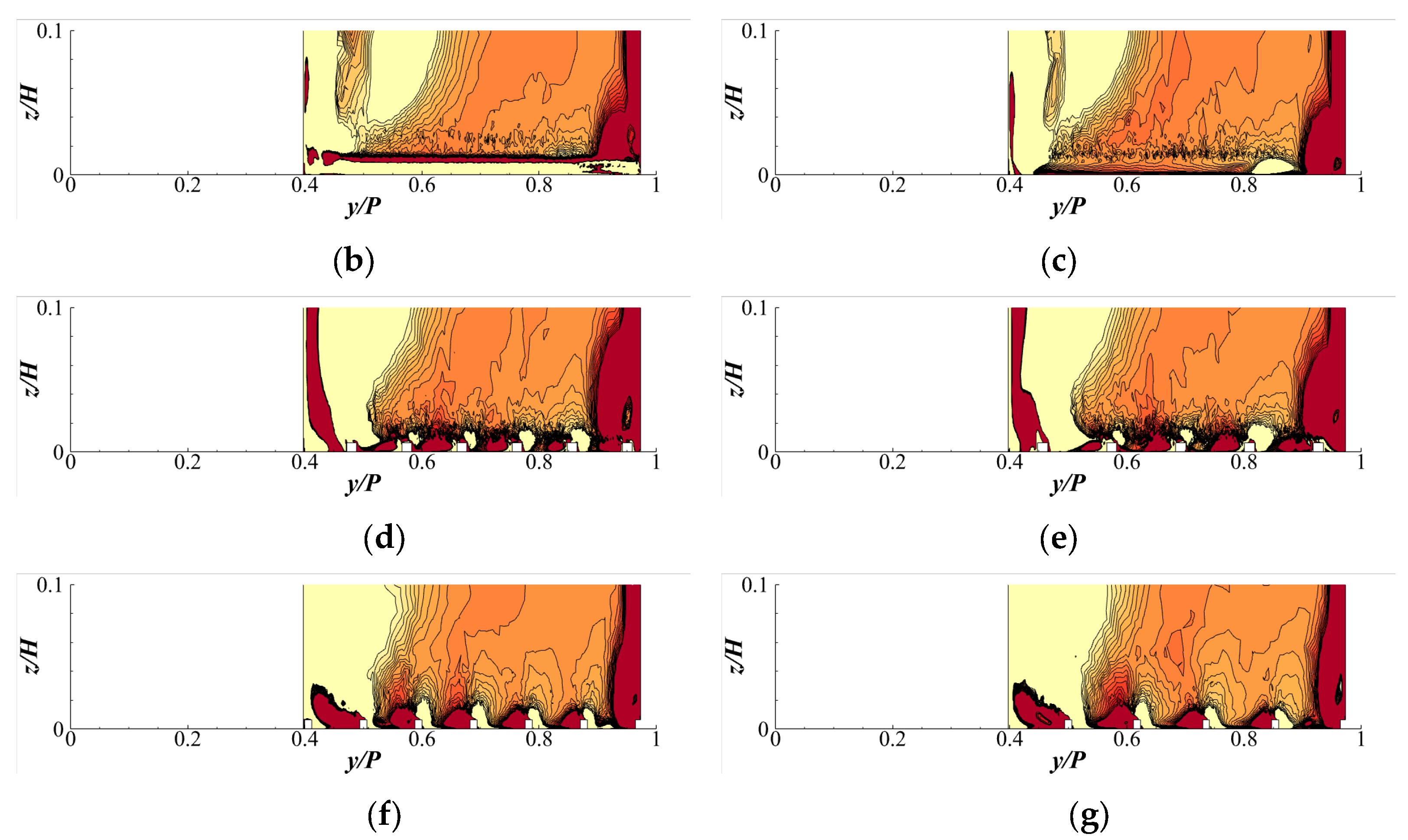
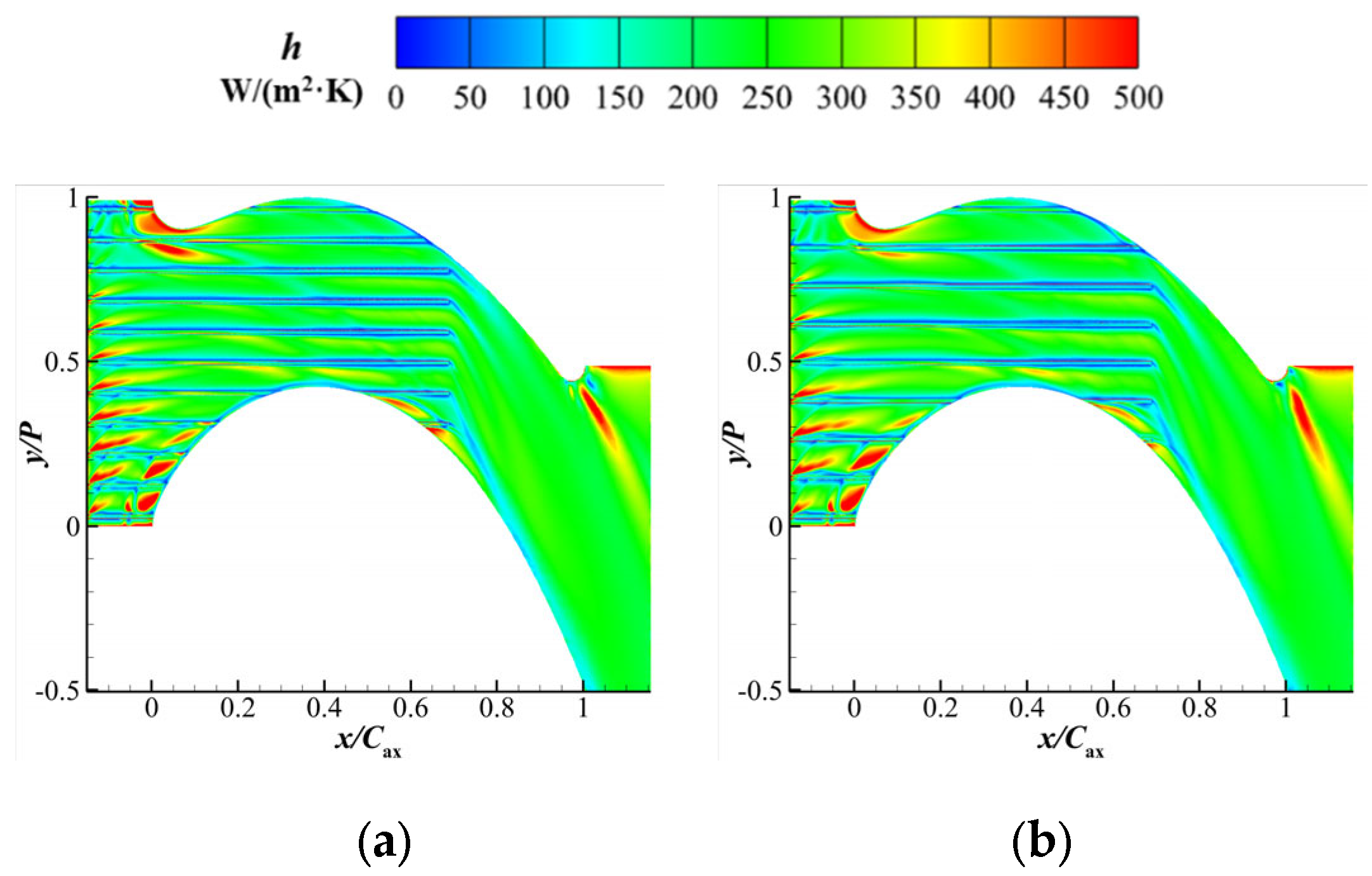
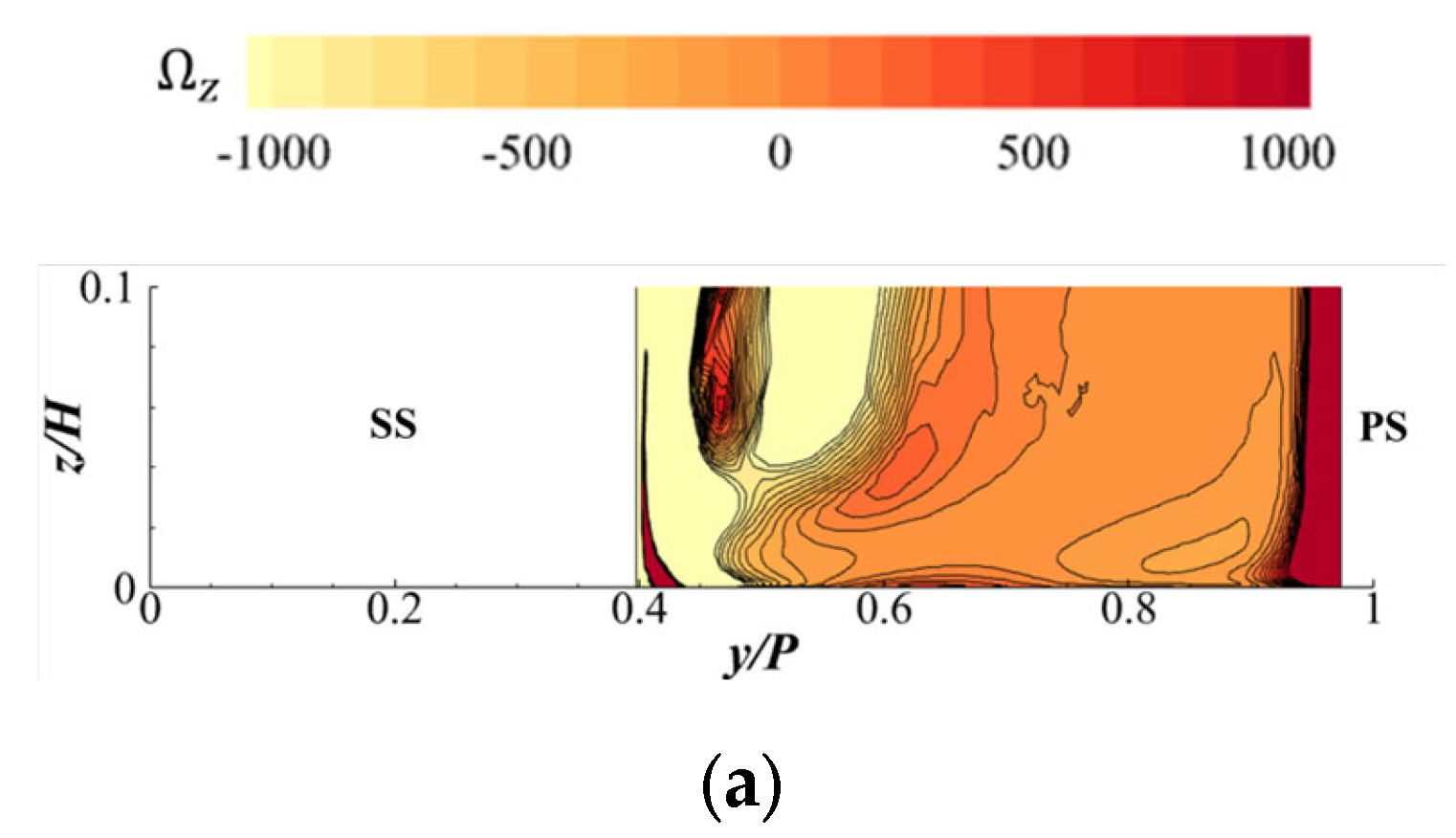
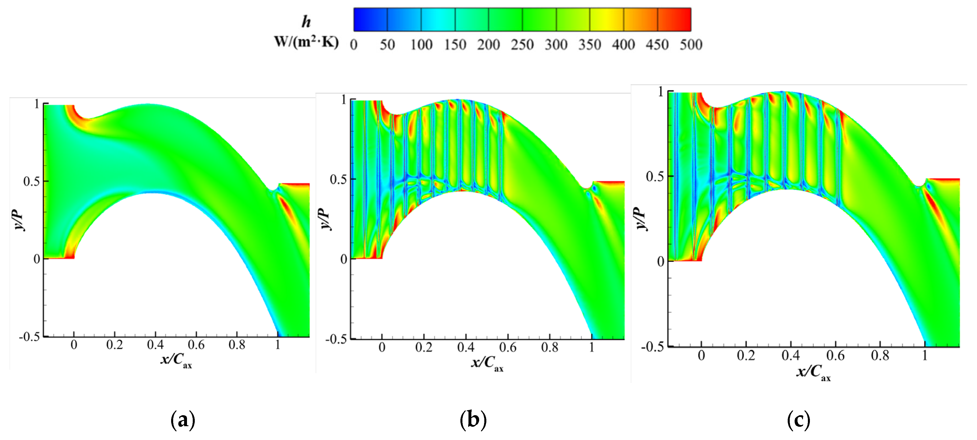
3.2. Heat Transfer Characteristic

The general consensus indicates that the rib will inevitably cause heat transfer enhancement, which has an adverse influence on the turbine cascade. However, the last section indicates that the ribbed enwall possesses the advantage of film cooling whether for the endwall surface or the SS of the blade. Therefore, this section mainly focuses on the heat transfer of the interaction between the rib and mainstream for the uncooling case. Meanwhile, the original endwall was used for comparison. The mainstream was the same as that in the last section, which was 40 m/s.
The heat transfer coefficient (h) is defined as Equation (6):
h = Δ q T w T a w = q w T w T a w
It is necessary for the h calculation to be calculated twice for acquiring the adiabatic wall-temperature ( T a w ) and constant wall-temperature ( T w ), respectively. The q w represents the heat flux on the endwall surface when the wall was set as the constant-temperature condition. Therefore, through subtraction of the two calculation results, the h of the endwall was obtained.
The comparison of the original endwall and horizontal case is shown in Figure 12. For the original endwall, there were mainly three regions of high h. The first region pointed at the LE of the blade (SS and PS). Due to the stagnation of the mainstream here and the horseshoe vortex, the first region presented an obvious trajectory of high-h distribution. The second region pointed at the leading edge, which was caused by the wake. These regions presented a high value of h. The last high-h region pointed at the passage, which was caused by the PV. Although the magnitude of high h was lower than those of the others, its range coincided with the PV, which is extensive. These three regions of high h were the basic model for turbine cascade. For the horizontal case, the high-h region was still in the vicinity of the LE. However, the region was separated by the rib channel, showing the discontinuity. The streamline was curved due to the rib and thus the high-h sub-region was partially shifted along the rib in each rib channel, where h was enhanced. Second, in the vicinity of the horseshoe vortex (SS leg, y/P ≈ 0.5), a low-h region was presented. This is because the intensity of the area around the horseshoe vortex decreased. It is speculated that this is a comprehensive result of the interaction between the horseshoe vortex and the rib-like vortex. In the vicinity of the PS corner, there was another high-h region, which was caused by the crossflow and rib-like vortex. As stated in the last paragraph, the high h was more obvious in the PV coverage region. It indicated that the rib enhanced the disturbance around the endwall, which is dominated by the rib-like vortex. Therefore, two high-h sub-regions were distributed on both sides of each rib channel in the vicinity of the throat, which were caused by PV and cross-flow, respectively. In addition, the effect of rib spacing did not show too much a difference for the horizontal case, indicating that the h distribution was nearly the same.
The h of the tilted case is shown in Figure 13. Note that the rib orientation was pointed straight to the LE of the PS. The flow in the rib channel was versus the horseshoe vortex and thus the stagnation line, presenting a line of low h, in front of the LE. The flow in the rib channel presented a tendency along the rib geometry, meaning that the rib-like vortex offset the secondary flow to some extent. Therefore, it is unclear whether the horseshoe or the PV would offset the original position, and the h presented a unique distribution. It is worth noting that the high-h region was distributed at each outlet of the rib channel, which proved the combination effect of the rib-like vortex and PV.
The h of the vertical case is shown in Figure 14. Along the axial direction, the first high-h region was shown at the inlet of endwall, which was also the beginning position for the ribs. The mainstream impacted the rib and thus formed the vortex, like the horseshoe formed in the front of the LE. Similar to the tilted case, the vertical rib was axially straight to the LE. Thus, the stagnation line, caused by the horseshoe vortex, was present in both LEs of the two blades. It is worth noting that the high-h region, caused by the PV, was not as obvious as the other rib cases, which indicated that the PV was weakened by the vertical rib and, thus, it is beneficial for the cooling design for this rib layout. In addition, another high-h region appeared near the throat of the SS, which was dominated by the rib-like vortex instead of the corner vortex.
The intensity of the rib-like vortex was a combination of the local mainstream, secondary flow, and rib geometry. In this paper, the rib geometry consists of two factors: rib spacing and rib type (exactly the layout orientation, which is relative to the local direction of the mainstream). The influence brought by the rib would spread in the downstream direction of the cascade, which would lead to the aerodynamic loss at the outlet of the cascade. The total pressure loss coefficient (Cpt) is defined as Equation (7).
C p t = P t , m P t , l o c a l P t , m P s , o u t
Figure 15 shows the Cpt at the position of x/Cax = 1 for the original endwall and ribbed endwall. The PV of the upper endwall and lower endwall could be reflected in the contour whether for the original endwall or the ribbed endwall. The difference between them was mainly reflected here. Generally, the Cpt of the ribbed endwall increased for the magnitude and range in the position of the PV for the lower endwall. For the horizontal rib case, the PV was lifted. This is because the disturbance of the mainstream, which was caused by the rib, was more serious as the rib orientation was nearly parallel to the mainstream.
To present the quantized aerodynamic loss, the laterally averaged Cpt is shown in Figure 16. In general, the original endwall exhibited better aerodynamic characteristics compared to the others. For the horizontal case, the major aerodynamic loss focused on the position around 0.3–0.6 z/H, which was larger than those of the other ribbed cases. This was mainly caused by the combination effect of the upper PV and lower PV, which was lifted by the rib-to-mainstream disturbance. For the tilted case, the major aerodynamic loss focused on the position around 0.2–0.3 z/H, which indicated that the intensity of PV was enhanced by the tilted rib. For the vertical cases, the aerodynamic loss performed better than other ribbed cases, despite the little difference between the vertical and tilted cases.
To present the comprehensive performance of endwall modification with the micro-scale rib, the area-average of η and h with the original endwall and ribbed endwall are shown in Figure 17. The increments and decrements in the ribbed endwall are highlighted with better and worse performance, respectively, compared with the base case (original endwall). From a comprehensive perspective, the tilted and vertical rib showed an obvious advantage on film cooling with little difference in the heat transfer characteristic (less than 1%), among which the vertical rib endwall with an s value of 8 mm presented the best increment (26.9%) in η . The horizontal rib exhibited not only a decrease in η but also an increase in h, which indicated that the rib layout should consider the flow direction of the mainstream. In addition, the heat transfer of the tilted rib presented a slight increase with 0.9% and 2.9%.

4. Conclusions

In this paper, the original endwall and ribbed endwall were numerically investigated, and the effect of the rib on the cooling and heat transfer characteristics was analyzed. In addition, the phantom cooling, flow pattern, and aerodynamics were also studied to present a comprehensive evaluation for the ribbed endwall. The conclusions are as follows:
(1)
The rib-like vortex changed the flow of the coolant and had various impacts on the cooling characteristic. The cooling characteristic of the ribbed endwall performed generally better than the original endwall (excluding the horizontal rib). The difference between the ribs is caused by the layout of the rib, which is related to the direction of the local mainstream. Specifically, when the rib is parallel to the mainstream, it benefits the cooling characteristic, and vice versa.
(2)
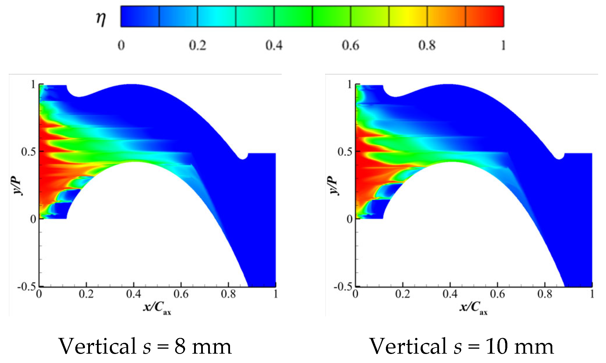
The reason for the difference in phantom cooling among different ribbed endwalls is due to the flow guiding effect of ribs on the coolant and whether the coolant dissipated before it reached the SS of the blade. So, the vertical ribs exhibit the best phantom cooling performance compared with horizontal and tilted ribs. For the tilted ribs, the phantom cooling would not perform well, since the rib direction guided the coolant to the opposite direction. Horizontal ribs exhibited the worst phantom cooling performance for the dissipated coolant before reaching the SS of the blade. The case of vertical s = 8 mm had the best cooling performance on the endwall surface (an increase of 26.9%, compared with original endwall) and the SS of the blade.
(3)
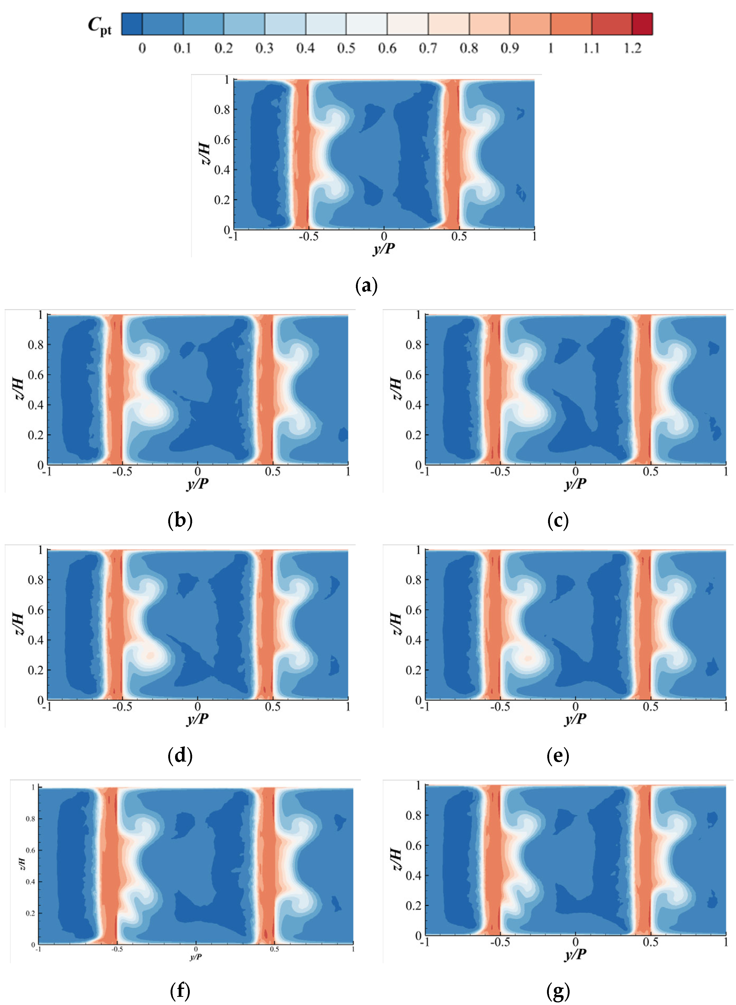
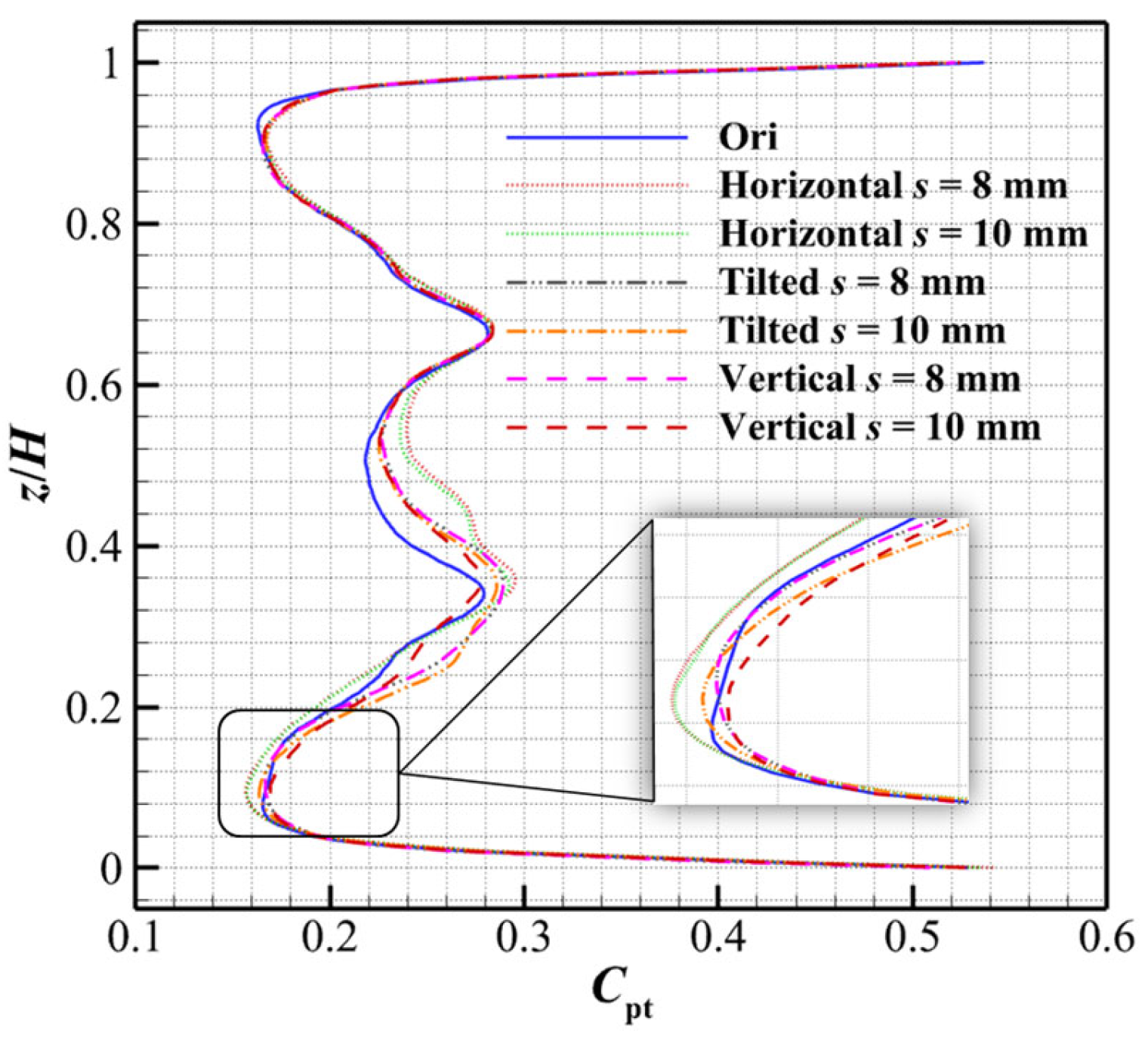
Compared with the cooling characteristic, the heat transfer of the ribbed endwall mainly depends on the combination of the secondary flow and rib-like vortex. The horizontal and tilted rib interfered most with the mainstream and thus caused a negative impact on the heat transfer. The vertical rib had the smallest influence on the heat transfer characteristic, because the high-h region, caused by the PV, was inhibited by the vertical rib layout. In addition, the ribbed endwall increased the aerodynamic loss, which was present in different z/H positions.

Author Contributions

Conceptualization, Y.S. and W.Z.; methodology, Z.L. and Y.S.; software, Z.L. and Y.S.; validation, Y.L. and W.Z.; formal analysis, Y.S.; investigation, Y.L. and Z.L.; resources, Z.F.; data curation, Y.S.; writing—original draft preparation, Y.S.; writing—review and editing, Y.S.; visualization, Z.F. and Z.L.; funding acquisition, Z.L. All authors have read and agreed to the published version of the manuscript.

Funding

This research was funded by the National Science and Technology Major Project (J2019-III-0007-0050).

Institutional Review Board Statement

Not applicable.

Informed Consent Statement

Not applicable.

Data Availability Statement

The data presented in this study are available on request from the corresponding author. The data are not publicly available due to privacy.

Conflicts of Interest

The authors declare no conflict of interest.

Nomenclature

PSPressure side
SSSuction side
LELeading-edge
TETrailing-edge
PVPassage vortex
MPGMid-passage gap
MFRMass flow ratio
η Film cooling effectiveness
xx axial length
Caxaxial chord distance
Ppitch-wise
Hpassage height
hrib height, (mm)
srib spacing, (mm)
wrib width, (mm)
Mblowing ratio
ReReynolds number
UmMainstream velocity, (m/s)
Tm,inTemperature of mainstream inlet, (K)
Tc,inTemperature of coolant inlet, (K)
TawAdiabatic wall temperature, (K)
Ω z Vorticity of z-direction
uvelocity
hheat transfer coefficient, (W/(m2·K))
q Heat flux, (W/m2)
q w Heat flux on the endwall surface
C p t Total pressure loss coefficient
P t , m Total pressure of mainstream
P t , l o c a l Total pressure of local position
P s , o u t Static pressure of outlet

References

  1. Pasinato, H.D.; Squires, K.D.; Roy, R.P. Measurements and Modeling of the Flow and Heat Transfer in a Contoured Vane-Endwall Passage. Int. J. Heat. Mass. Transf. 2004, 47, 5685–5702. [Google Scholar] [CrossRef]
  2. Lynch, S.P.; Thole, K.A. The Effect of Combustor-Turbine Interface Gap Leakage on the Endwall Heat Transfer for a Nozzle Guide Vane. J. Turbomach. 2008, 130, 041019. [Google Scholar] [CrossRef]
  3. Oke, R.A.; Simon, T.W.; Burd, S.W.; Vahlberg, R. Measurements in a Turbine Cascade Over a Contoured Endwall: Discrete Hole Injection of Bleed Flow. In American Society of Mechanical Engineers Digital Collection; ASME Press: Munich, Germany, 2000. [Google Scholar]
  4. Mahmood, G.I.; Acharya, S. Measured Endwall Flow and Passage Heat Transfer in a Linear Blade Passage with Endwall and Leading Edge Modifications. In Proceedings of the ASME Turbo Expo 2007, Montreal, QC, Canada, 14–17 May 2007; Volume 6 Parts A and B. ASME: New York, NY, USA, 2007; pp. 917–930. [Google Scholar]
  5. Li, X.; Ren, J.; Jiang, H. Experimental Investigation of Endwall Heat Transfer with Film and Impingement Cooling. J. Eng. Gas. Turbines Power 2017, 139, 101901. [Google Scholar] [CrossRef]
  6. Choi, S.M.; Park, J.S.; Chung, H.; Park, S.; Cho, H.H. Upstream Wake Effect on Flow and Heat Transfer Characteristics at an Endwall of First-Stage Blade of a Gas Turbine. Exp. Therm. Fluid. Sci. 2017, 86, 23–36. [Google Scholar] [CrossRef]
  7. Xu, Q.; Du, Q.; Wang, P.; Liu, J.; Liu, G. Computational Investigation of Film Cooling and Secondary Flow on Turbine Endwall with Coolant Injection from Upstream Interrupted Slot. Int. J. Heat. Mass. Transf. 2018, 123, 285–296. [Google Scholar] [CrossRef]
  8. Zhang, L.; Yin, J.; Koo Moon, H. The Effects of Vane Showerhead Injection Angle and Film Compound Angle on Nozzle Endwall Cooling (Phantom Cooling). J. Turbomach. 2014, 137, 021003. [Google Scholar] [CrossRef]
  9. Yang, X.; Liu, Z.; Liu, Z.; Feng, Z.; Simon, T. Turbine Platform Phantom Cooling from Airfoil Film Coolant, with Purge Flow. Int. J. Heat. Mass. Transf. 2019, 140, 25–40. [Google Scholar] [CrossRef]
  10. Zhang, L.; Yin, J.; Liu, K.; Hee-Koo, M. Effect of Hole Diameter on Nozzle Endwall Film Cooling and Associated Phantom Cooling. In American Society of Mechanical Engineers Digital Collection; ASME Press: Montréal, QC, Canada, 2015. [Google Scholar]
  11. Chen, P.; Zhao, K.; Li, X.; Ren, J.; Jiang, H. Effects of Varying Non-Axisymmetric Contours of the Turbine Endwall on Aerodynamics and Heat Transfer Aspects:A Sensitivity Analysis Study. Int. J. Therm. Sci. 2021, 161, 106689. [Google Scholar] [CrossRef]
  12. Chen, Z.; Su, X.; Yuan, X. Cooling Performance of the Endwall Vertical Hole Considering the Interaction between Cooling Jet and Leading-Edge Horseshoe Vortex. J. Therm. Sci. 2022, 31, 1696–1708. [Google Scholar] [CrossRef]
  13. Burdett, T.A.; Ullah, I.; Wright, L.M.; Han, J.-C.; McClintic, J.W.; Crites, D.C.; Riahi, A. Upstream and Passage Endwall Film Cooling of a Transonic Turbine Vane. J. Thermophys. Heat. Transf. 2023, 37, 394–403. [Google Scholar] [CrossRef]
  14. Zhang, W.; Li, F.; Xie, Y.; Ding, Y.; Liu, Z.; Feng, Z. Experimental and Numerical Investigations of Discrete Film Holes Cooling Performance on a Blade Endwall with Mid-Passage Gap Leakage. Int. J. Heat. Mass. Transf. 2023, 201, 123550. [Google Scholar] [CrossRef]
  15. Yang, X.; Zhao, Q.; Liu, Z.; Liu, Z.; Feng, Z. Film Cooling Patterns over an Aircraft Engine Turbine Endwall with Slot Leakage and Discrete Hole Injection. Int. J. Heat. Mass. Transf. 2021, 165, 120565. [Google Scholar] [CrossRef]
  16. Wang, K.; Ao, Y.; Zhao, K.; Zhou, T.; Li, F. Improving Film Cooling Efficiency with Lobe-Shaped Cooling Holes: An Investigation with Large-Eddy Simulation. Appl. Sci. 2023, 13, 4618. [Google Scholar] [CrossRef]
  17. Zhao, Z.; Xi, L.; Gao, J.; Xu, L.; Li, Y. Numerical Study on Cooling Performance of a Steam-Cooled Blade Based on Response Surface Method. Appl. Sci. 2023, 13, 6625. [Google Scholar] [CrossRef]
  18. Wang, Z.; Feng, Z.; Zhang, X.; Peng, J.; Zhang, F.; Wu, X. Improving Cooling Performance and Robustness of NGV Endwall Film Cooling Design Using Micro-Scale Ribs Considering Incidence Effects. Energy 2022, 253, 124203. [Google Scholar] [CrossRef]
  19. Yang, X.; Wu, Y.; Zhao, Q.; Feng, Z. Study on Film Cooling for Aero-Engine Turbine Endwalls with Various Small-Scale Surface Structures. Aerosp. Sci. Technol. 2022, 123, 107444. [Google Scholar] [CrossRef]
  20. Du, K.; Chen, Q.; Li, Y.; Sunden, B.; Liu, C.; Li, W. Numerical Investigation on Flow and Cooling Characteristics of a Micro-Ribbed Vane Endwall. J. Therm. Sci. 2023, 32, 786–799. [Google Scholar] [CrossRef]
  21. Shote, A.S.; Mahmood, G.I.; Meyer, J.P. Influences of Large Fillets on Endwall Flows in a Vane Cascade with Upstream Slot Film-Cooling. Exp. Therm. Fluid. Sci. 2020, 112, 109951. [Google Scholar] [CrossRef]
  22. Celik, I.B.; Ghia, U.; Roache, P.J.; Freitas, C.J. Procedure for Estimation and Reporting of Uncertainty Due to Discretization in CFD Applications. J. Fluids Eng. 2008, 130, 078001. [Google Scholar] [CrossRef]
  23. Du, K.; Li, J. Numerical Investigations on Aerodynamic and Cooling Characteristics of the Turbine Vane Endwall with Micro-Ribbed Structure. J. Eng. Thermophys. 2019, 40, 520–528. [Google Scholar]
Figure 1. Geometric parameters of ribbed endwall.
Applsci 13 12594 g001
Figure 2. Schematic of original endwall and ribbed endwall with different rib types. (a) Original; (b) Horizontal rib; (c) Tilted rib; (d) Vertical rib.
Applsci 13 12594 g002aApplsci 13 12594 g002b
Figure 3. Computational model (pink: blade; orange: endwall; gray: hub).
Applsci 13 12594 g003
Figure 4. Comparison of results. (a) Experimental apparatus; (b) Test article for verification; (c) Comparison of laterally averaged η ( η l ) on the endwall.
Applsci 13 12594 g004
Figure 5. Detail of mesh topology.
Applsci 13 12594 g005
Figure 6. η of horizontal ribs.
Applsci 13 12594 g006
Figure 7. η of tilted ribs.
Applsci 13 12594 g007
Figure 8. η of vertical ribs.
Applsci 13 12594 g008
Figure 9. Phantom cooling effectiveness on the SS of blade (LE: leading edge; TE: trailing edge). (a) Original; (b) Horizontal s = 8 mm; (c) Horizontal s = 10 mm; (d) Tilted s = 8 mm; (e) Tilted s = 10 mm; (f) Vertical s = 8 mm; (g) Vertical s = 10 mm.
Applsci 13 12594 g009
Figure 10. η l of endwall with various rib types.
Applsci 13 12594 g010
Figure 11. Streamwise vorticity of the plane x/Cax = 0.5. (a) Original; (b) Horizontal s = 8 mm; (c) Horizontal s = 10 mm; (d) Tilted s = 8 mm; (e) Tilted s = 10 mm; (f) Vertical s = 8 mm; (g) Vertical s = 8 mm.
Applsci 13 12594 g011aApplsci 13 12594 g011b
Figure 12. h of the original case and horizontal rib case. (a) Original; (b) Horizontal s = 8 mm; (c) Horizontal s = 10 mm.
Applsci 13 12594 g012
Figure 13. h of the tilted case. (a) Tilted s = 8 mm; (b) Tilted s = 10 mm.
Applsci 13 12594 g013
Figure 14. h of the vertical case. (a) Vertical s = 8 mm; (b) Vertical s = 10 mm.
Applsci 13 12594 g014
Figure 15. Cpt of plane in x/Cax = 1. (a) Original; (b) Horizontal s = 8 mm; (c) Horizontal s = 10 mm; (d) Tilted s = 8 mm; (e) Tilted s = 10 mm; (f) Vertical s = 8 mm; (g) Vertical s = 10 mm.
Applsci 13 12594 g015
Figure 16. Laterally averaged Cpt of plane in x/Cax = 1 for all cases.
Applsci 13 12594 g016
Figure 17. Area-averaged values of η and h for endwall cases. (a) Film cooling; (b) Heat transfer.
Applsci 13 12594 g017
Table 1. Information for endwall modification.
BenefitsDemerits
Contoured endwall
  • Reduce flow loss
  • Improve the use of leakage
  • The effect of loss reduction is not good as non-axisymmetric endwall
Non-axisymmetric endwall
  • Reduce flow loss
  • Provide more uniform flow of outlet
  • Difficulty for cooling design
Micro-scale rib
  • Increase cooling performance
  • Adverse impact on heat transfer
Chamfer of blade root
  • Reduce aerodynamic loss
  • Difficulty for cooling design
Table 2. Grid independence details obtained using the GCI method.
MeshTotal Number of CellsArea-Averaged η Deviation/%GCI/%
Coarse23,989,2360.168418.08——
Moderate35,531,7160.1528091.933.17
Fine66,834,0420.1555910.140.18
Richardson extrapolation——0.155815————
Table 3. Boundary conditions.
Um (m/s)40
Tm,in (K)298.15
Tc,in (K)288.15
MFR (%)1
Disclaimer/Publisher’s Note: The statements, opinions and data contained in all publications are solely those of the individual author(s) and contributor(s) and not of MDPI and/or the editor(s). MDPI and/or the editor(s) disclaim responsibility for any injury to people or property resulting from any ideas, methods, instructions or products referred to in the content.

