1. Introduction
Gypsum, as an important mineral resource, plays a significant role in socio-economic development. In the southern regions of China, due to unregulated mining of private gypsum mines, numerous unknown goaf areas have been created, posing potential hazards to subsequent transportation infrastructure construction and operational safety. Gypsum is a soluble mineral, especially in environments with groundwater, making it prone to dissolution [
1]. Therefore, the stability of abandoned gypsum mine areas can easily be influenced by groundwater, potentially leading to the dissolution and damage of the mineral body. Room-and-pillar mining is a commonly used method for gypsum mining, where mined-out pillars or sidewalls are left underground for an extended period. Under the long-term effects of overlying rock loads and groundwater infiltration, these supports can sustain damage and deterioration. Many gypsum mine pillars become unstable due to prolonged damage beyond their limits, resulting in extensive collapse disasters [
2,
3,
4].
The stability issues of abandoned gypsum mine areas have garnered increasing attention. Yang et al. (2015) [
5] highlighted several serious accidents caused by collapses in abandoned gypsum mines. Studies on various engineering cases have indicated that proper assessment and treatment measures can effectively ensure the stability of gypsum mines, reducing the occurrence of geological disasters. Therefore, conducting research on the stability and instability mechanisms of gypsum mine goaf areas holds significant importance [
6,
7]. The assessment of gypsum mine goaf area stability involves various tasks, such as rock mechanics tests, geological structure investigations, and stress field analysis. Through field investigations and laboratory tests, the mechanical parameters of the gypsum rock mass, as well as the geological structures and stress field distributions, are determined in order to assess the stability of the goaf area.
Henley et al. (1976) [
8] employed an energy theory to analyze the dynamic process of instability in gypsum mine systems. Auvray et al. (2004, 2008) [
9,
10] used SEM (scanning electron microscope) to observe the weathering process of gypsum mine pillars in abandoned mine areas. The results showed that the weathering rate of gypsum mine pillars is related to the duration of mining activities. The time-related characteristics of gypsum mine pillars are closely linked to the air humidity inside the abandoned mine area, which is influenced by ventilation conditions and seasonal variations. Zhao et al. (2010) [
11] applied a catastrophe theory in combination with the safety factor reduction method to evaluate the stability of abandoned mine roofs.
Numerical simulation methods have been widely applied in the stability assessment of gypsum mine areas. By establishing numerical models, these methods simulate mining processes such as stress distribution, displacement, deformation, and fracture within the gypsum mine, predicting its stability and optimizing remediation measures. Pierce and Cundall (2004) [
12] simulated surface subsidence caused by block caving mining using the discontinuous fracture model and particle flow algorithm. Their research provided important numerical simulation methods for understanding and predicting ground subsidence mechanisms due to mining activities. Cai et al. (2007) [
13] proposed a new method based on the GSI (Geological Strength Index) system, obtaining relevant parameters of jointed rock masses through field investigations and experimental measurements for numerical simulation and engineering design. This method is significant for assessing the stability of jointed hard rock and designing underground mining projects. Alejano [
14] and Gomez (2013) developed a stability assessment method for blocky rock mass caverns by combining field observations and numerical simulations, which considered fracture characteristics and stress distribution in the rock mass, enabling a more accurate evaluation of the stability in such rock mass caverns. Fidelibus [
15] and Soccodato (2002) simulated stress and displacement distributions during the underground limestone mining process in the Apulia region of Italy, studying stability and collapse mechanisms during mining activities. Zou and Konietzky (2016) [
16] simulated the inflow of karst water during underground mining activities, analyzing the interaction between groundwater and mining operations.
In 2009, the local government temporarily closed the mining operation of this gypsum mine. However, due to financial difficulties, no investigation or proper disposal of the abandoned mining area took place after the mine closure. Until now, only one inclined shaft was left operational for water pumping maintenance. Consequently, there is a severe lack of reliable preliminary data concerning this abandoned mining area, resulting in a complete lack of knowledge regarding the conditions of the drifts and stope rooms. This lack of information presents significant challenges for conducting a stability analysis and implementing engineering solutions for the abandoned mining area.
Based on the research achievements in the engineering geological investigation, rock mass quality assessment, and geometry model construction, this study considered the current and long-term state of an actual abandoned gypsum mine in south China. It utilized numerical methods and employed the IMASS (Itasca Model for Advanced Strain Softening) constitutive model to conduct a stability analysis of the abandoned gypsum mine in terms of its current and long-term state.
2. Engineering Background
2.1. Engineering Geology
During the engineering geological survey for the Baiguo-Nanyue highway construction in Hunan province, China, an abandoned gypsum mine was discovered beneath the route (
Figure 1). Considering that there is a proposed bridge above this abandoned mining area, and that the gypsum rock is highly soluble in water, the potential for extensive pillar or roof collapse in this area is significant, which could undoubtedly lead to a serious geologic hazard. Therefore, in accordance with relevant construction standards, this section of the highway was designated as an unstable site, necessitating a more comprehensive investigation and stability analysis.
The topography above the abandoned mining area is characterized by an alluvial plain with a relatively simple terrain, where the maximum altitude difference is approximately 3.0 m. Based on the report of the geological survey from boreholes, the stratum in this area predominantly consists of Quaternary Holocene sedimentary layers, including fill, silty clay, fine sand, and gravelly soil; the bedrock is composed of Cretaceous argillaceous siltstone; and below 10 to 20 m burial depth is a layer of medium-weathered argillaceous sandstone with a silty fine-grained structure and medium-thick layered arrangement, and joint cracks are generally slightly developed. Notably, this layer contains a 1.5 to 4.0 m thick stratum of green gypsum. The geological structure of this area lacks extensive development, and the underlying bedrock follows a monoclinal structure with a nearly horizontal bedding orientation. The geophysical exploration and borehole data indicate that the goaf’s burial depth beneath the highway central line is between 30 and 80 m, with the goaf’s height measuring around 3 m.
2.2. 3D Laser Scanning and Detection Results
Traditionally, the assessment methods for abandoned mining areas include geological drilling, geophysical prospecting, 3D laser scanning detection, and similar techniques. Among these methods, 3D laser scanning technology is particularly valuable, as it accurately captures spatial information in the form of point clouds at the area’s boundaries. Furthermore, this technology enables the generation of precise 3D models through specialized point cloud processing programs.
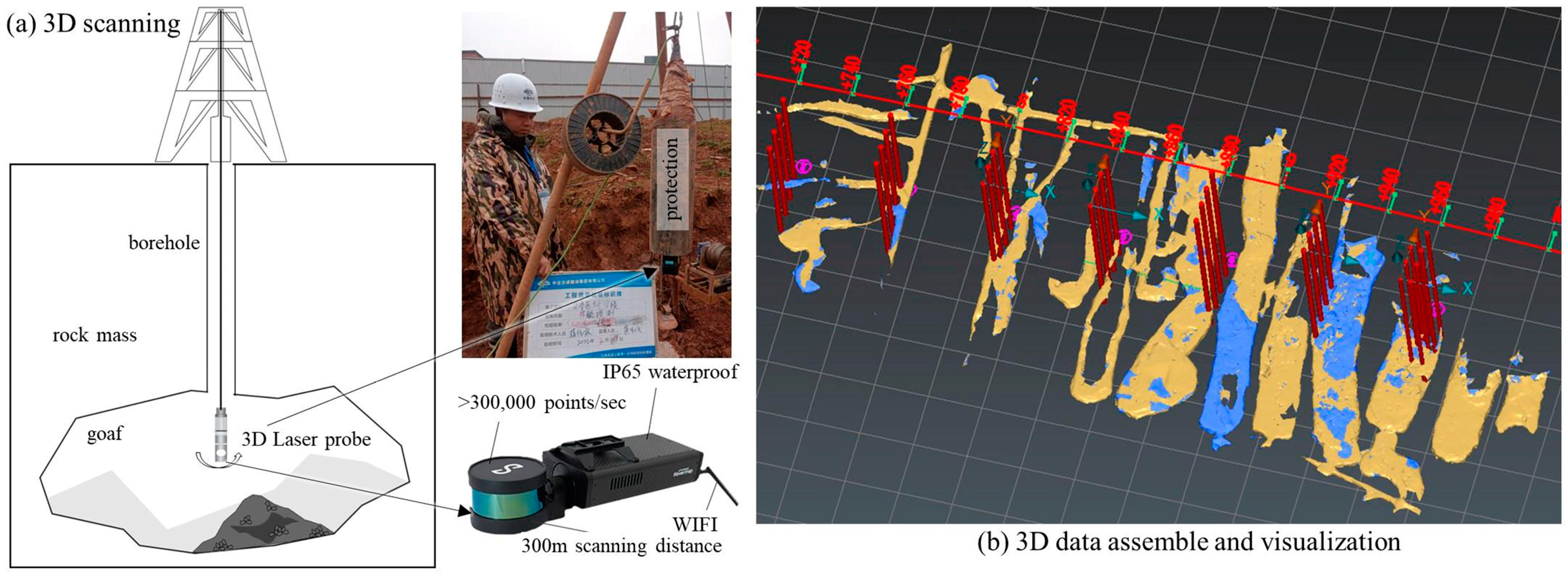
The project utilizes the HVM100 SLAM 3D laser scanning system, which is a continuous scanner with SLAM technology developed by the Commonwealth Scientific and Industrial Research Organisation (CSIRO) of Australia. It utilizes laser ranging to acquire information about the surrounding environment. The data acquisition speed is 300,000 points per second, with a weight of only 1.8 kg. It has a distance accuracy of ±4 cm, an angular resolution of 0.1°, and a measurement range of 360° × 360° with no blind spots.
The highway construction company undertook 3D laser scanning detection for the abandoned mining area. The detection process is depicted in
Figure 2: A laser scanner was inserted into the abandoned mining area through a drillhole; the scanner, capable of a 360-degree rotation, continuously collected data on the distances and angles of the measured points during the detection process; data accuracy was meticulously maintained by controlling three parameters, including the scanning center’s coordinates, the scanning angle, and the measuring distance. In total, over 400 drillholes were strategically placed near the highway, and the data collection for all drillholes was successfully carried out using a 3D laser detection system.
The 3D point cloud data collected from these drillholes were processed through a dedicated 3D point cloud data processing system, leading to the reconstruction of a 3D spatial model for the abandoned mining area, as illustrated in
Figure 2b. This approach facilitates the automatic calculation of the roof area and the volume of the abandoned mining area.
2.3. Engineering Impact and Status Evaluation
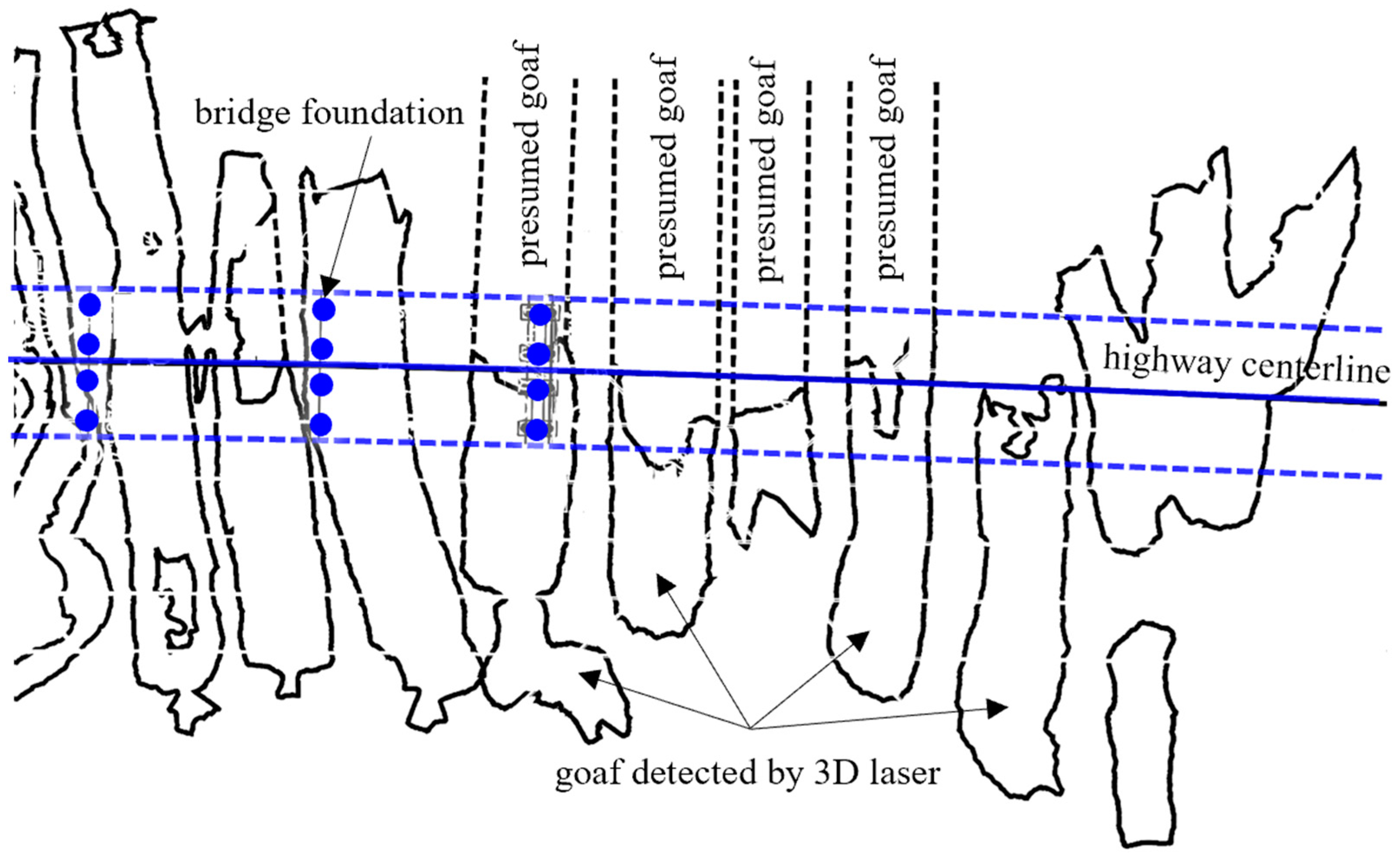
Based on the findings from the 3D laser detection,
Figure 3 illustrates the plan view of the abandoned mining area adjacent to the highway bridge foundations. The mining method employed here was room-and-pillar mining, a technique involving the excavation of “rooms” into the rock mass while leaving behind “pillars” of unexcavated material to support the roof. This creates a grid-like pattern of extracted areas and supporting structures, balancing the need for resource extraction with maintaining the stability of the surrounding environment. The primary mine shaft runs in a north–south direction. The ore body is present as stratoid beds with an average mining thickness of around 3 m. In this specific case of room-and-pillar mining, the pillars and remaining structures were not sufficiently robust to prevent some level of collapse and instability, which is indicative of the challenges and considerations that come with this mining method. Among the mining rooms, only a few have been backfilled with waste slag, while the majority remain unfilled, lacking significant lateral constraints. The exposed area of the abandoned region, near the bridge foundation, is extensive, accounting for roughly 84% of the total ore body area. The mining rooms are predominantly elongated, with their orientation approximately orthogonal to the highway central line. The maximum length of the mining room is about 150 m, which is much longer than the room width. The roof depth varies between 40 and 60 m, and the mining rooms span from 14 to 24 m, with an average span of 16 m, maintaining an equal width on both sides. It is worth noting that the average width of the side walls and pillars is only 3 m, and many pillars were severely overmined, and some even collapsed. This highlights another aspect of room-and-pillar mining, where the size and integrity of the pillars are crucial to the long-term stability of the mined areas. There is a recurring pattern of interconnected mining rooms, and a significant portion of these rooms exhibit signs of roof collapse, underscoring the importance of carefully planned and executed room-and-pillar mining to mitigate such risks.
The detection results indicate that several pillars within the mining area have already experienced subsidence. Moreover, the volume and extent of the abandoned mining area raise concerns. Consequently, the stability of the supporting system becomes increasingly challenging, especially in the face of long-term pressure transfer and water-induced softening. The enduring stability of the abandoned mining area is primarily contingent upon the stability of the roof and the rib. When the exposed areas of the roof and rib become extensive, instability becomes almost certain. Under these circumstances, there is an urgent need to conduct a comprehensive stability analysis of the abandoned mining area. This analysis is vital to ensuring the highway’s safety and averting potential catastrophic accidents.
According to the results of the geological survey and 3D laser detection, although the gypsum mine has left roof pillars during the mining process, due to the large volume of the empty area, some of the pillars have already collapsed. It will be difficult to maintain the stability of the pillars under the influence of long-term stratum pressure transfer and softening of the water seepage. The long-term stability of the mining area will be mainly controlled by the stability of the roof and sidewalls. When the exposed area of the roof plate and sidewalls of the mining area is too large, the roof plate and sidewalls will be destabilized, which may result in the room collapsing, or even in large subsidence. In order to ensure the safety of the upper highway construction and prevent catastrophic accidents induced by the destabilization of the mining area, it is urgent to analyze the stability of the abandoned mining area.
4. Numerical Analysis
4.1. The Excavation Process and Current Stability Analysis
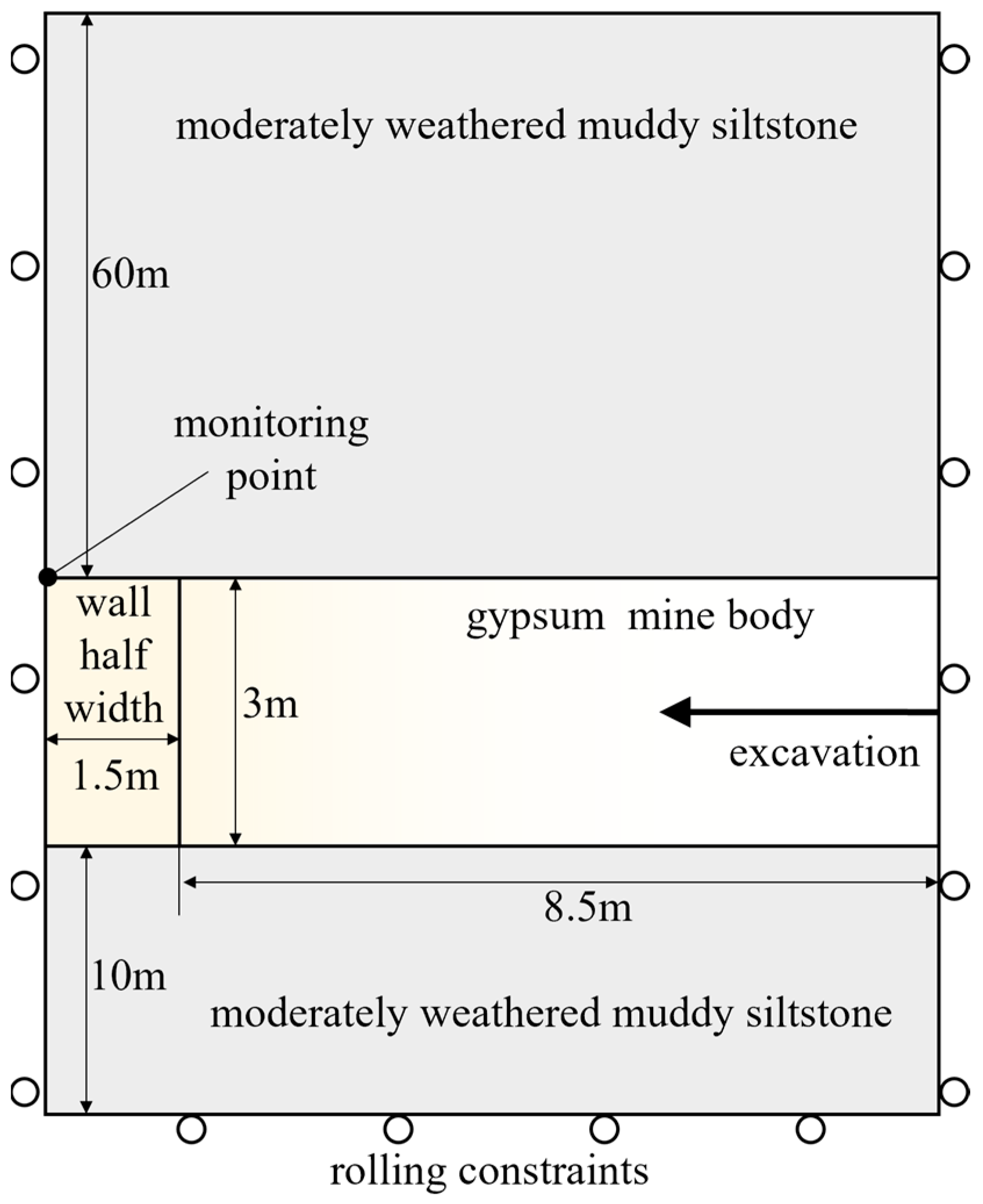
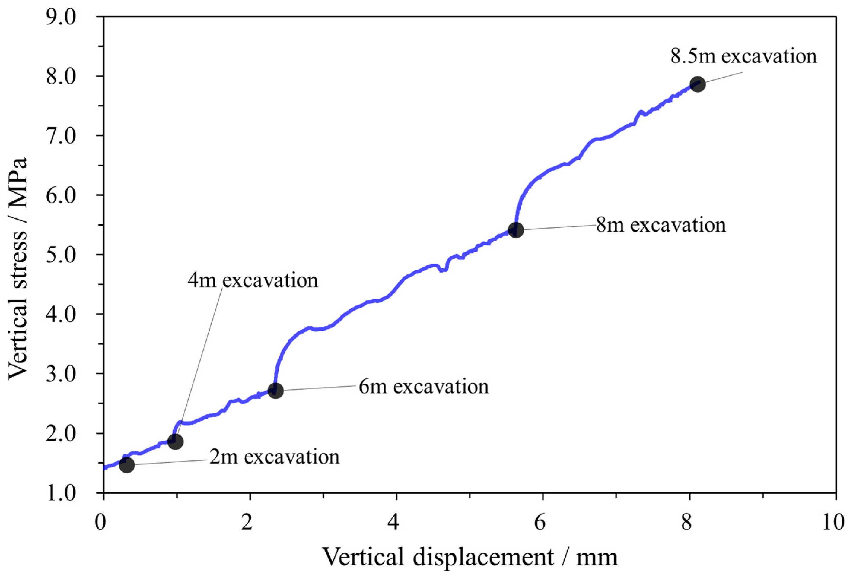
The excavation process of the numerical model commenced on the right side of the mining room. The excavation procedure required periodic suspensions at every 2 m length interval to allow the stress in the surrounding rock mass to achieve equilibrium.
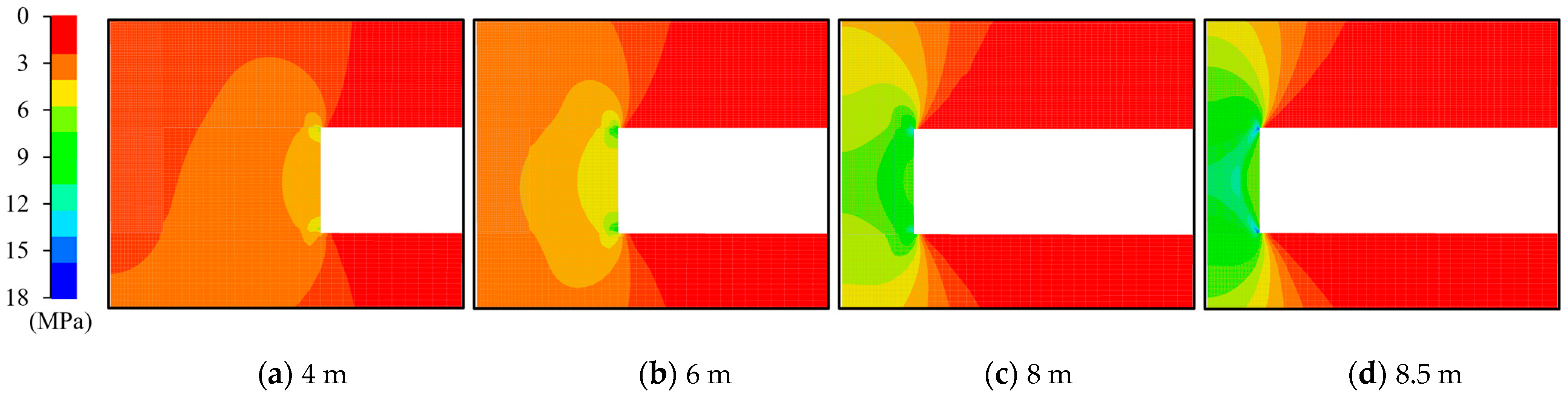
Figure 6 provides an insight into the vertical stress and displacement at the top of the sidewall throughout the excavation, while
Figure 7 presents the vertical stress distribution in the surrounding rock mass during various excavation stages.
Evidently, when the excavation face maintained a considerable distance from the sidewall, only minor disturbances were observed. The vertical stress at the monitoring point altered from 1.5 MPa to 2.5 MPa as the excavation length reached 6 m. However, as the thickness of the sidewall diminished, the increment in stress escalated rapidly. For instance, when the excavation depth reached 8 m, the vertical stress surged to 5.5 MPa. The analysis of the stress distribution illustrated that the vertical stress at the monitoring point exhibited intermediate levels within the overall stress distribution of the sidewall.
Furthermore, the phenomenon of stress concentration stemming from the excavation emerged initially at the corner of the sidewall and subsequently propagated towards the central region. Upon the completion of the excavation, the vertical stress in the central region reached 10 MPa, yet it could peak at 18 MPa in the corner. This occurrence indicates that the stress on the sidewall during the excavation process could closely approach the uniaxial compressive strength of gypsum rock in a laboratory (25 MPa). The stress concentration might lead to localized rock damage at the corners and free surface. Nonetheless, the general stability of the sidewall in the current stage remains assured.
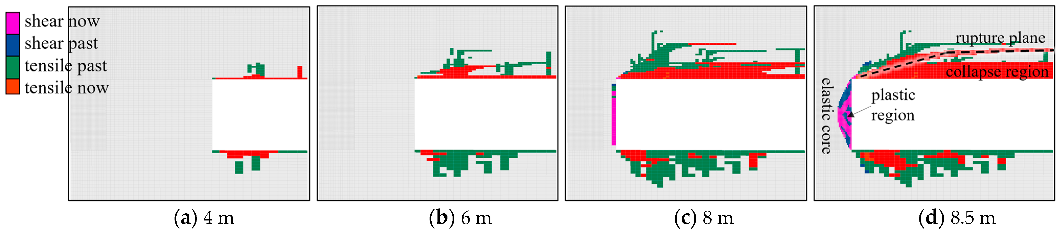
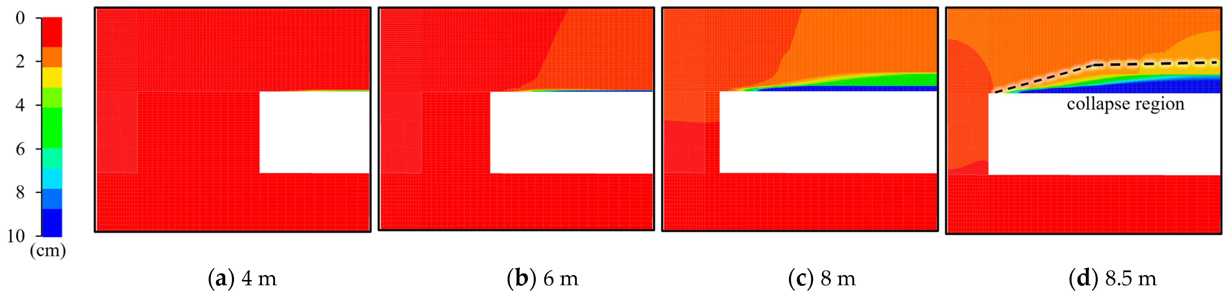
Figure 8 illustrates the progression of the plastic state of the surrounding rock mass at various excavation stages. Following the completion of excavation, the rock roof of the abandoned mining area lost its support, leading it to bend downward under the pressure exerted by the overlying rock. Due to the relatively weak tensile strength of the rock, elements within a certain thickness of the roof underwent tension failure as the stress surpassed the tensile strength limit. As the excavation concluded, the failed elements within the roof connected with each other, forming a rupture surface. Consequently, a roof collapse occurred, resulting in a nearly 1 m thick fallen region at the mining room top. Contrasted with its tensile strength, gypsum’s compressive strength is notably stronger. Hence, it was not until the excavation length reached 8 m that the sidewall began to yield (
Figure 8c). Upon the completion of the excavation, both sides of the side wall gave rise to a shear zone
Figure 8d). The stress within the shear zone of the gypsum rock did not exceed its yield strength, adhering to the principles of elasticity. This region was enveloped and confined by the yield zone, experiencing a three-directional stress state. This region can be aptly termed the elastic core region of the sidewall.
In
Figure 8, “shear now” indicates that elements have entered shear failure during the current calculation step, while “tensile now” suggests that elements are currently experiencing tensile failure during the respective calculation step. “shear past” indicates a previous state of shear failure. “tensile past” denotes a previous state of tensile failure.
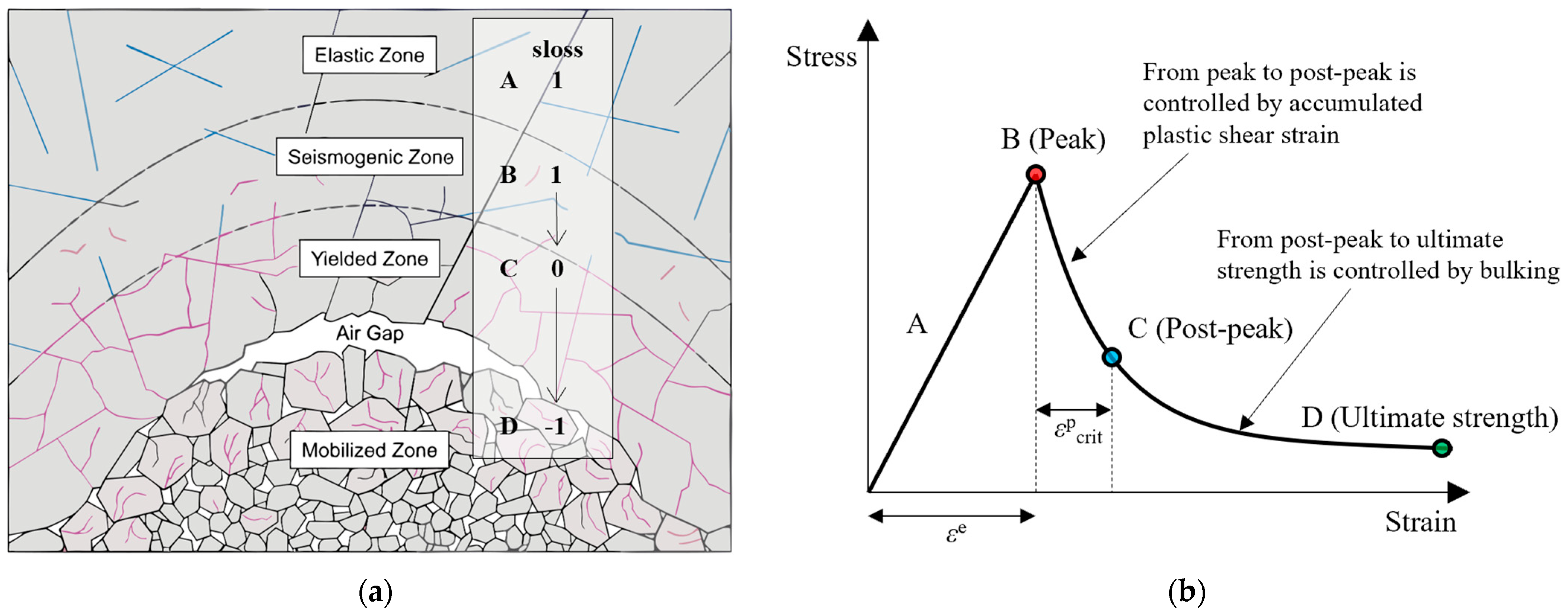
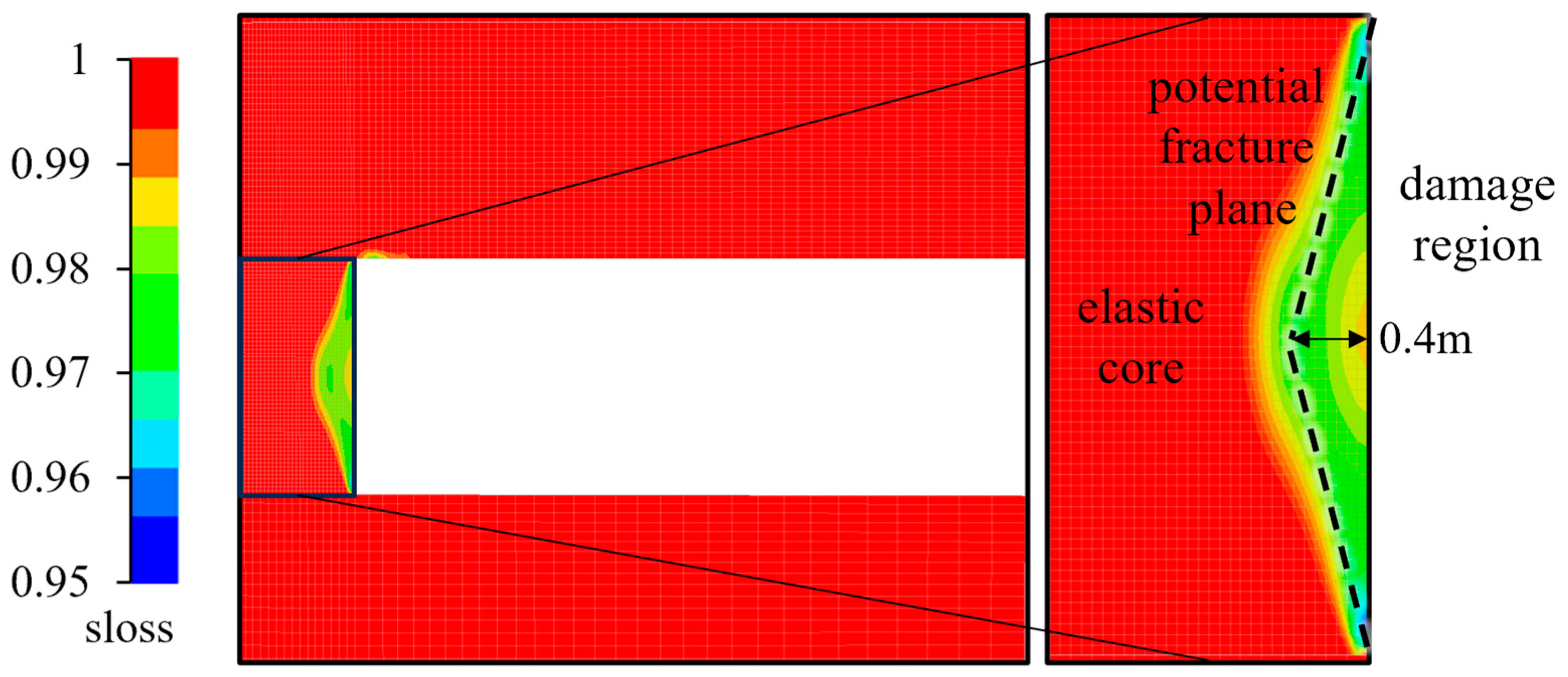
Compared with the plastic state, the IMASS model’s sloss indicator more accurately reflects the failure process of the brittle rock mass.
Figure 9 presents the distribution of the sloss index at the final excavation state. On both sides of the remaining sidewall, a region with sloss index values ranging from 0.95 to 1.0 was observed. This indicated that the stress within this zone had just exceeded the peak strength and had entered the stage of strength degradation. As the strength of the elastic core was still sufficient to bear the transferred stress from excavated room, the strength degradation did not escalate rapidly. Consequently, the sloss index remained slightly below 1.0.
The regions characterized by low sloss index values can be perceived as potential rupture surfaces. The stress within these regions was very close to or even surpassed the rock’s peak strength. While they might not experience immediate destruction, there is a high likelihood of further damage, rupture, and spalling failure from the sidewall to the empty room over the medium to long term. The rock mass within the potential rupture surface of the sidewall is referred to as the elastic core region, which is distributed in a “vertical barbell” form. This elastic core plays a pivotal role in bearing the overburden pressure over the long term.
Figure 10 illustrates the variation in the vertical displacement of the surrounding rock mass at different excavation stages. The roof of the excavated room initiated collapsing when the excavation length reached 8 m. The final maximum settlement of the roof was approximately 3 cm, while the maximum floor bulge was less than 1 cm. By the final stage, the sidewall remained stable, experiencing a maximum compression of less than 1 cm. In essence, noticeable deformation did not occur in the abandoned mining area throughout the excavation process, whether it was the roof or the floor. Moreover, horizontal displacement of the rock mass was less prominent than the vertical displacement, suggesting that both the roof and the sidewall were capable of maintaining stability in the excavation stage.
4.2. Medium- and Long-Term Stability Analysis
Based on the analyses in the last section, the numerical model of the abandoned mining area appears to remain stable during the excavation. However, some degree of damage did occur in the sidewall, leading to the formation of a relaxation region. This region may allow groundwater from upper layers to infiltrate the abandoned area through cracks and channels formed by the roof deformation. Over time, the relaxation region of the sidewalls will undergo softening and spalling, exposing the elastic core. This exposure will decrease the effective thickness and horizontal confining stress of the sidewall, leading to further damage and inevitably causing instability in the wall.
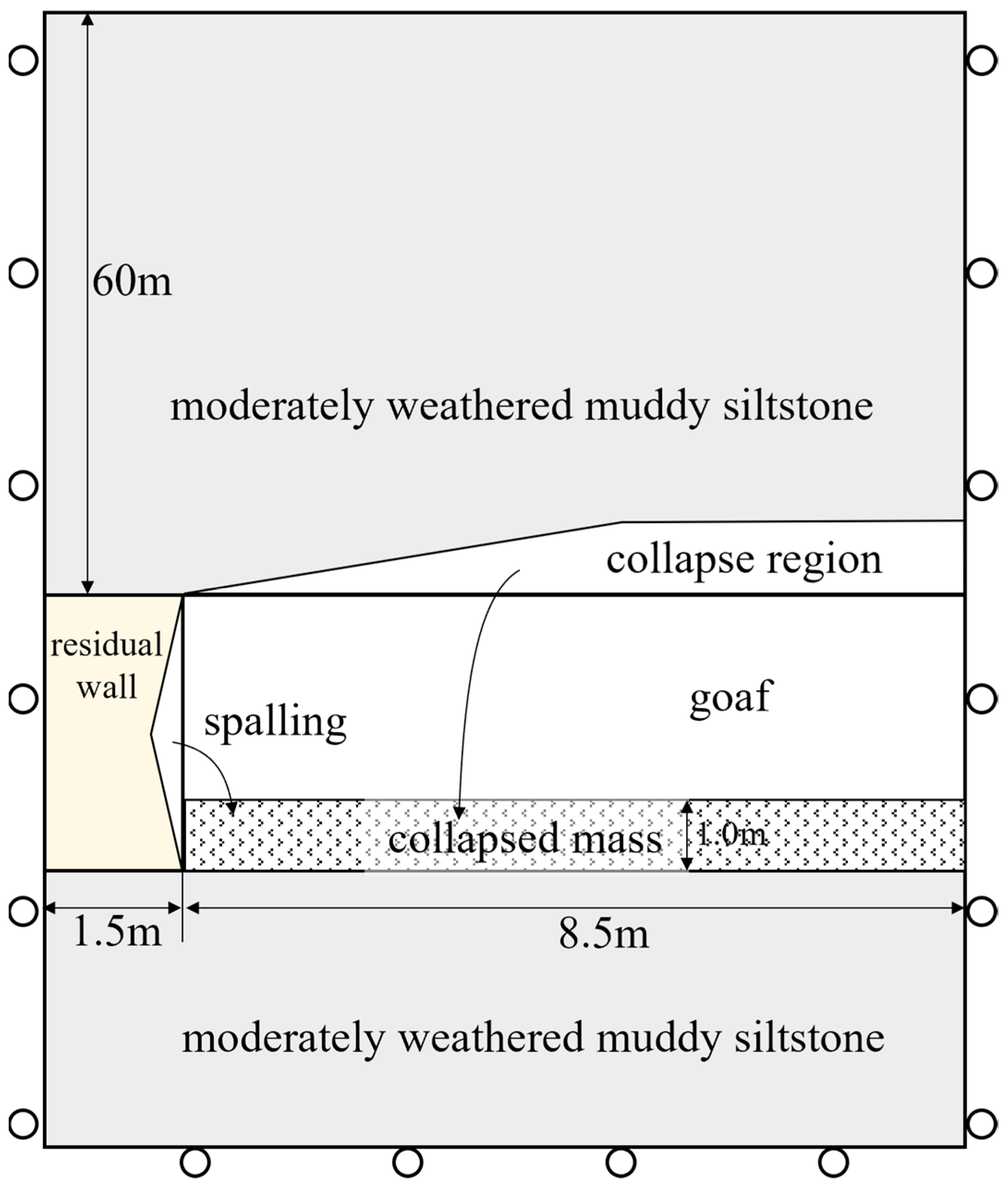
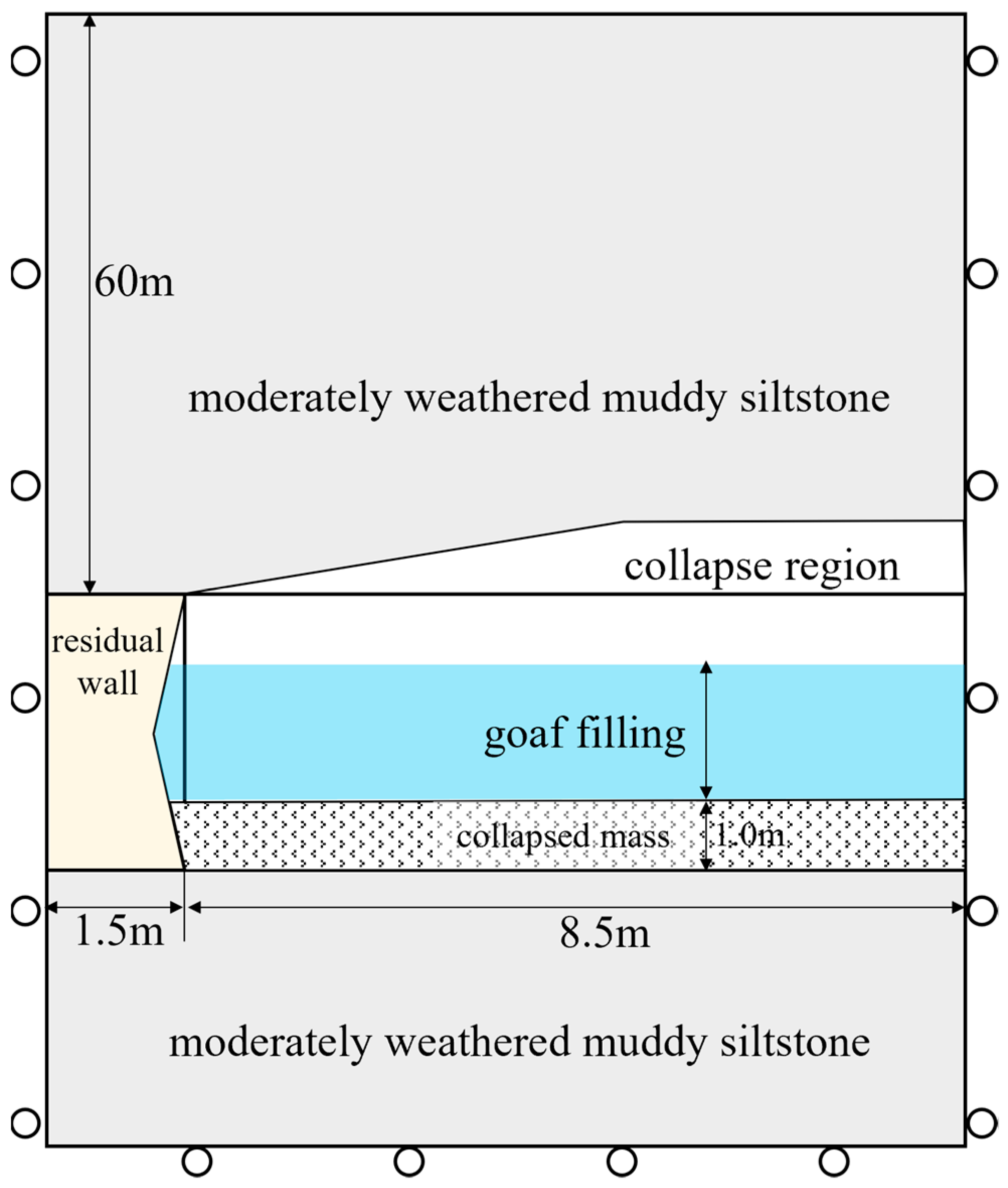
In light of this, a numerical model was established for further analysis, as depicted in
Figure 11. Several assumptions were made for this model. The collapsed roof area shown in
Figure 8 and the damaged sidewall area shown in
Figure 9 have been completely destroyed, forming a 1 m thick collapsed mass at the bottom of the abandoned mining area. Due to sidewall damage and spalling, its thickness has decreased by 0.1 m compared with the initial model. The constitutive law of the collapsed mass follows the Mohr–Columb model, with detailed parameters listed in
Table 2.
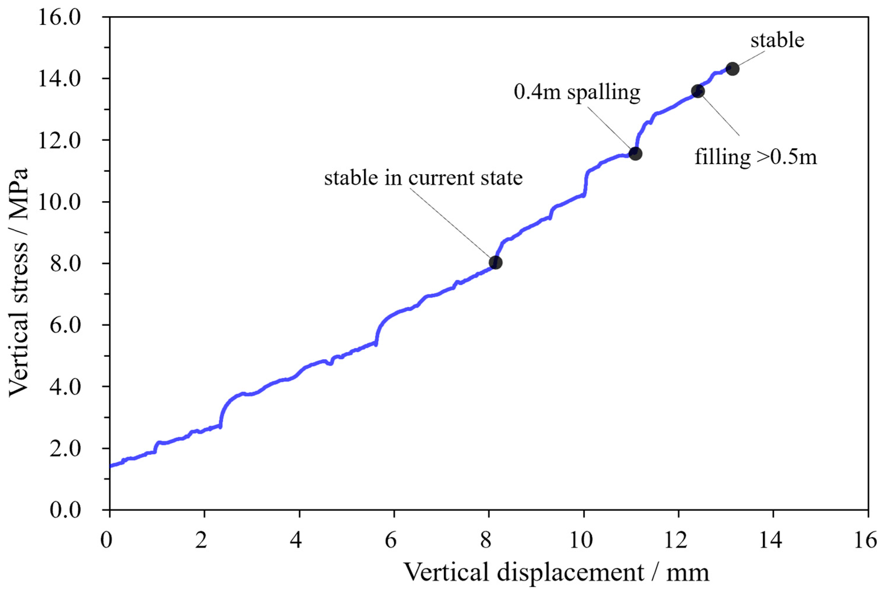
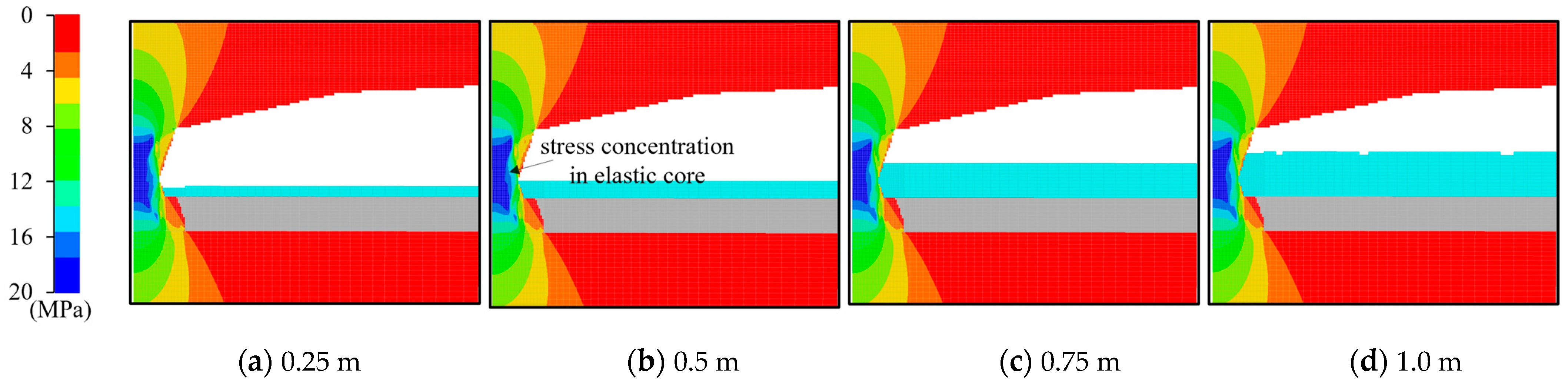
Figure 12 presents the vertical stress and displacement curves at the top of the sidewall, while
Figure 13 illustrates the distribution of the vertical stress in the surrounding rock mas under varying spalling thicknesses of the sidewall. With increasing spalling collapse, the vertical stress at the monitoring point gradually rises. The stress curve peaks at a spalling thickness of 0.4 m, after which it starts to decline in conjunction with a continuous increase in vertical displacement. This trend suggests that the sidewall has become unstable. Regarding
Figure 13, it indicates that as spalling intensifies, the elastic core experiences a significant increase in vertical stress. When the spalling thickness reaches 0.3 m, the elastic core is subjected to a vertical stress exceeding 20 MPa, which is close to the uniaxial compressive strength of gypsum rock in a laboratory (25 MPa). When the thickness reaches 0.4 m, the stress within the elastic core suddenly becomes disordered and then decreases, signaling a prelude to instability.
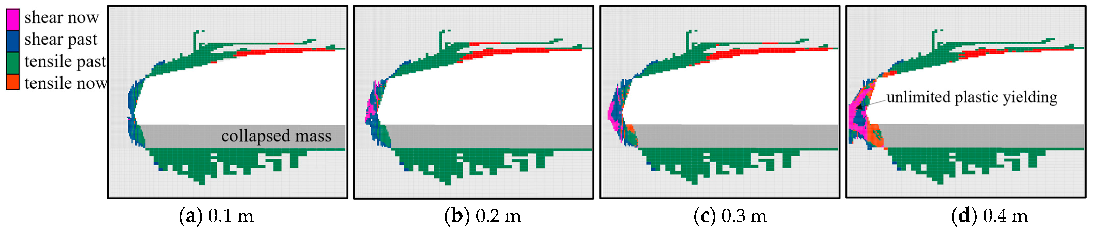
The evolution of the plastic elements (
Figure 14) reveals that the tensile damage area at the top of the abandoned mining area remains relatively unchanged following the collapse of the roof. This lack of significant change can be attributed to the loss of tensile strength in the collapsed area during the previous excavation and the subsequent rebalancing of stress in the rock mass outside the collapsed roof region. Consequently, removing this region of rock mass is unlikely to substantially impact the plastic state of the model. In essence, the critical factor for the long-term stability of the abandoned mining area is the condition of the sidewall.
Figure 14d illustrates that the shear plastic regions have become interconnected and cannot be constrained. Moreover, gypsum rock within the sustained plastic-yielding state exhibits a non-linear strain-softening behavior. After reaching the peak strength, it rapidly falls to the low residual strength.
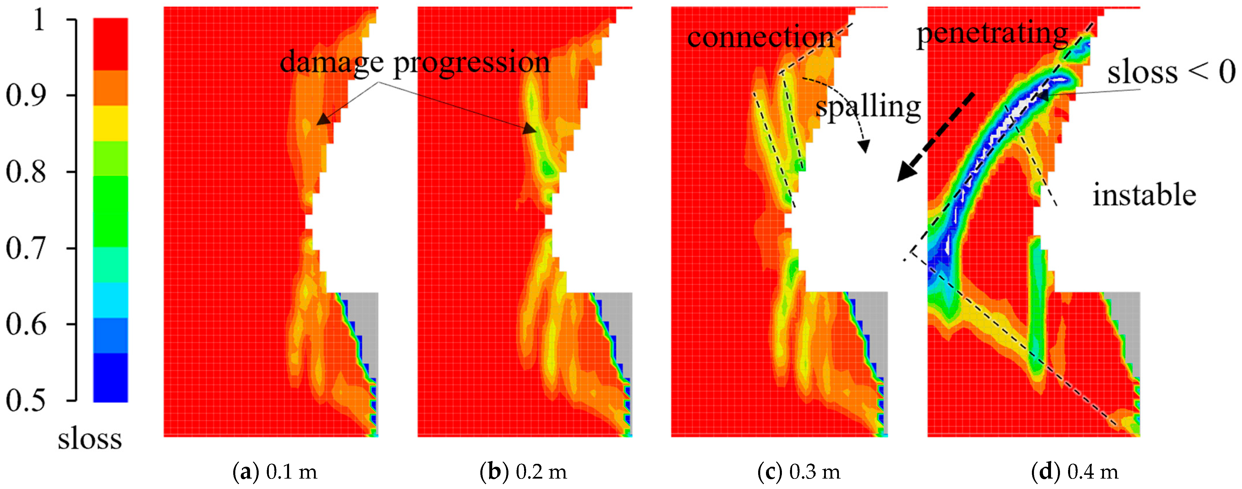
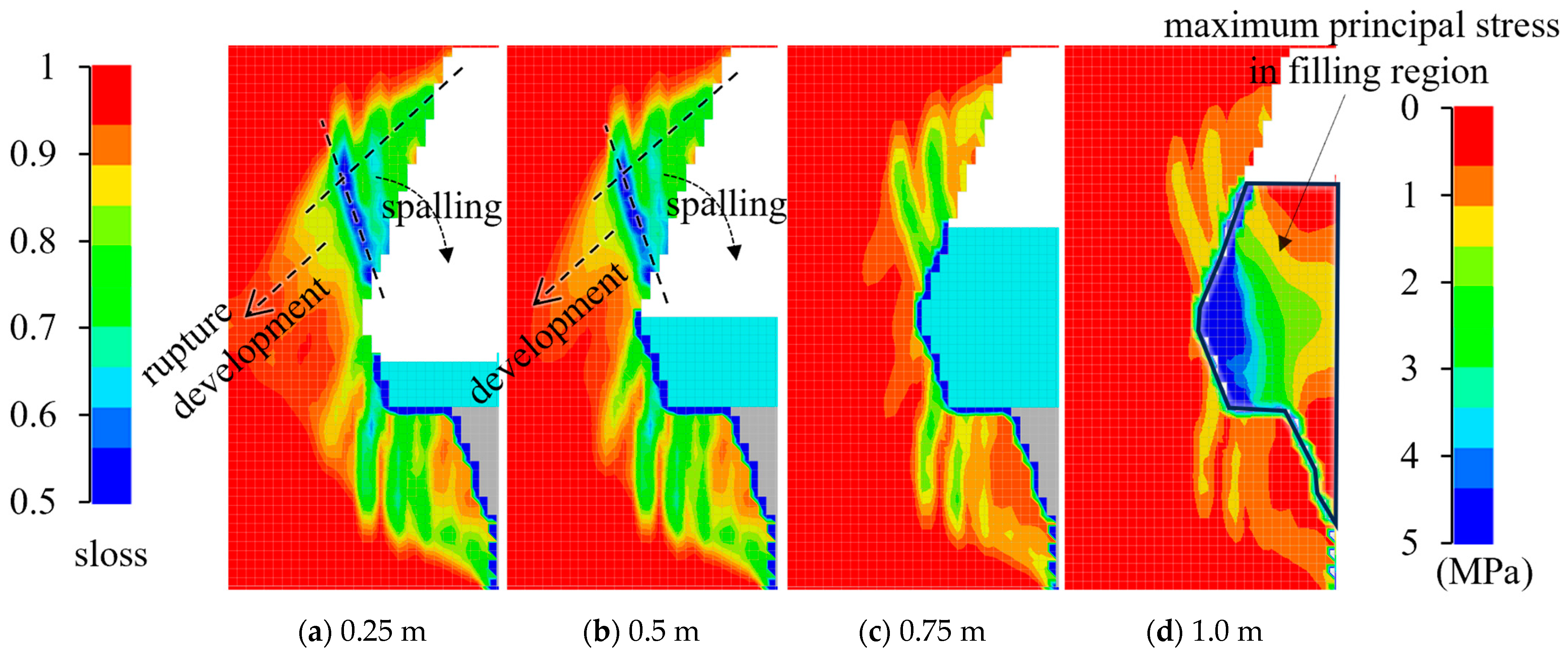
The sloss distribution index demonstrates that as the spalling of the sidewall expands, the gypsum rock continues to be damaged, with more elements gathering. This gathering signifies the collapsing mass and propagation of rock cracks. Ultimately, a macroscopic slip plane forms throughout the whole sidewall, leading to the overall instability in the abandoned mining area. In
Figure 15, the area where the sloss index < 0 indicates a complete rock mass failure. Damage bands penetrate the entire width of the sidewall, and the elastic core is yielding. Consequently, the safety of the abandoned mining area is compromised due to the inadequate thickness of the sidewall. The instability of the sidewall will manifest once the spalling reduces its thickness to 0.4 m. Without the implementation of protective treatment, this outcome is inevitable. Thus, it can be concluded that the long-term stability of the abandoned mining area cannot be ensured.
4.3. Filling Treatment Effect
As discussed earlier, the long-term stability of the sidewall cannot be ensured. Therefore, implementing a protective treatment is crucial to maintaining the integrity of the abandoned mining area. The application of mortar filling is a viable approach in this context. This method can effectively reduce deformation and improve the stress distribution and the overall stability of the rock mass.
Figure 16 illustrates the corresponding numerical model used to assess the impact of the mortar filling method under various conditions, with a spalling thickness of 0.4 m. The constitutive relationship of the mortar adheres to the Mohr–Columb model, and specific parameters are detailed in
Table 3.
The vertical stress and displacement curves at the top of the sidewall are presented in
Figure 17, while
Figure 18 depicts the vertical stress distribution in the surrounding rock mass under different conditions. The reinforcement provided by the mortar filling prevents a stress drop within the core compression region of the sidewall, as seen in
Figure 18d, resulting in a final stress interval ranging from 16 to 20 MPa. Nevertheless,
Figure 19 reveals that interconnected plastic zones still emerge when the mortar’s height is below half of the sidewall’s height. However, the plastic elements are constrained once the mortar’s height exceeds this threshold.
Figure 20 shows that an inadequate mortar filling height leads to significant damage development in the rock mass at the upper area of the sidewall, with a tendency towards deeper faulting. Conversely, a sufficient filling height restricts further damage progression in the sidewall’s rock mass and prevents surface softening and spalling due to groundwater seepage.
Figure 20d indicates the formation of a 5 MPa principal stress within the filled mortar near the sidewall, signifying that the filler can share the load carried by the sidewall. As a result, the mortar filling substantially enhances the lateral support of the sidewall, improves the stress distribution in the damaged rock mass, and prevents sidewall instability.


