Article

Study on Service Vibration Characteristics of High-Speed Train Disc Brake under Thermo-Solid Coupling

School of Mechanical Engineering, Dalian Jiaotong University, Dalian 116028, China
*
Author to whom correspondence should be addressed.
Appl. Sci. 2023, 13(22), 12361; https://doi.org/10.3390/app132212361
Submission received: 23 October 2023 / Revised: 10 November 2023 / Accepted: 13 November 2023 / Published: 15 November 2023

Abstract

:
This paper examines the effects of thermo-solid coupling and the influence of braking parameter changes on the vibration characteristics of high-speed train disc brakes. A multi-flexible body dynamics model of high-speed train disc brakes considering thermo-solid coupling was established to study the vibration characteristics of high-speed train disc brakes during service. The results show that the uneven distribution of temperature and stress produced during the brake disc’s service was the primary cause of the warping deformation of the brake disc, which prevented the brake disc and the brake pads from making sufficient contact and caused vibration while braking. By comparing the analytical findings of whether the model was subject to the coupling effect or not, the influence of thermo-solid coupling on the braking procedure was demonstrated from the standpoint of energy distribution. The severity of the high-speed train brake disc vibration gradually increased along with the braking pressure and initial speed. In addition, vibration aggravated the instability of the braking process, which could lead to thermoelastic instability and is harmful to the braking performance of the brake. These findings provide theoretical support for designing and manufacturing disc brakes for high-speed trains.

1. Introduction

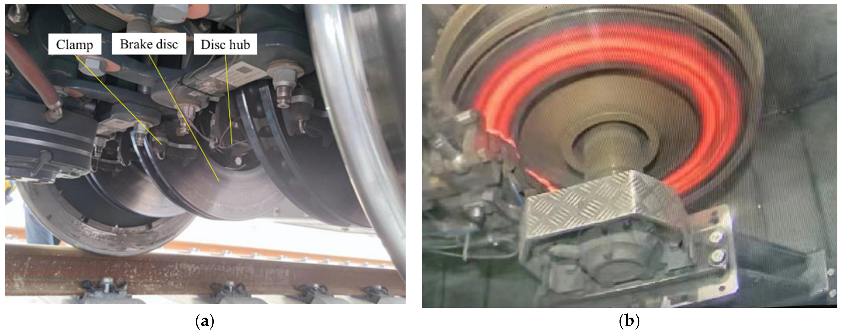
With the development of the rail transit industry and the continuous advancement of technology, the speed and transportation efficiency of high-speed trains have been greatly improved. As a crucial part of ensuring the safe and stable running of high-speed trains, disc brakes are commonly utilized, as shown in Figure 1a. The brake disc and brake pads convert the kinetic energy of the high-speed train into internal energy through friction during braking. This process generates significant heat, resulting in an uneven temperature field on the brake disc and brake pads, as shown in Figure 1b. Periodic thermal shock is then formed on the friction surface, which changes the contact state between the brake disc and brake pads and significantly affects the braking performance of disc brakes on high-speed trains.
To obtain the rules of the influence of heat on braking performance in the process of disc braking, many scholars have researched the temperature and stress distribution of the frictional heat generated by the brake during the braking process. Yevtushenko et al. [1] proposed a new numerical simulation method for the rotational motion of the brake disc based on the finite element method and used this method to study the temperature distribution characteristics of the ventilated disc and the solid disc under emergency braking conditions. Popescu et al. [2] took the emergency braking condition as an example to study the thermal and mechanical properties of the disc brake system and used the COMSOL structural heat transfer and solid mechanics module to obtain the brake friction heat and the thermal stress caused by heat. Mithlesh et al. [3] analyzed the stress distribution of the brake disc while braking, and the results showed that changing the contact area between the brake disc and brake pad can effectively reduce stress. Saffari et al. [4] provide an analytical framework based on the third-order shear deformation theory (TSDT) to conduct a comprehensive thermo-vibro-acoustic evaluation of a multi-layered asphalt system subjected to a harmonically rectangular. The study found that higher road surface temperature will lead to an increase in softness and rut depth under moving loads, and an increase in load speed will lead to a higher frequency and increased amplitude of the pressure wave. Dubale et al. [5] performed numerical simulations for heat transfer analysis of different types of brake discs and obtained the temperature and stress distribution of different types of brake discs under emergency braking conditions. Jiregna et al. [6] performed a thermo-solid coupling analysis of the brake disc based on the FEM method to obtain the temperature gradient distribution of the brake disc and the maximum temperature on the friction surface of the brake disc. In conclusion, it is clear that when a train brakes, the friction between the brake disc and brake pads produces a significant amount of heat, causing the brake to operate in a thermo-solid coupling environment and reducing its safety service performance, which seriously affects the working efficiency of high-speed train disc brakes.
Along with the force-heat effect in the braking process described above, braking vibration also has an impact on the braking efficiency of disc brakes on high-speed trains. Numerous scholars have investigated the vibration phenomenon that occurs during disc braking and the mechanism that causes it. Park et al. [7] found in their study that the runout of the end face of the brake disc causes periodic changes in the friction force, which leads to the occurrence of vibrations. Lyu et al. [8] used the transient analysis method and the complex eigenvalue method to study the vibration behavior of the disc brake for the vibration caused by friction and found that the work done by the friction force will cause the vibration of the braking system. Lazzari et al. [9] found in their study that the interaction between the brake disc and the brake pad is the main cause of brake vibration generation. Zhang et al. [10] studied the contact pressure distribution of the brake friction pair based on a multi-body dynamics approach and proposed that fluctuations in braking pressure can lead to the occurrence of vibration. Gao et al. [11] explored the cause of brake vibration from the perspective of vibration energy and found that the brake disc is the main component that vibrates during the braking process. Chen et al. [12] studied the mechanism of friction vibration by combining complex eigenvalue analysis and transient dynamic analysis methods and proposed that the repeated separation-reattachment process of friction pairs is an important mechanism leading to vibration. To study the mechanism of disc brake vibration, Zhu et al. [13] conducted finite element analysis under different braking conditions and proposed that there is a coherent relationship between braking pressure and initial braking speed. The friction pair’s relative velocity and the contact pressure of the contact interface are not linear during the braking operation. The disc brake will vibrate while working because of the friction force and the thermal-mechanical coupling effect during the braking operation. High-speed train disc brake braking efficiency might decline due to brake vibration that causes relative displacement between the brake disc and brake pad. In some cases, the brake disc may even be unable to complete the braking process.
Scholars have carried out many studies on the vibration characteristics of disc brakes to reveal the influence of braking vibration on the braking performance of disc brakes. Ghorbel et al. [14] proposed a two-degree-of-freedom disc brake model and obtained the influence of brake pressure and speed on vibration stability. Wang et al. [15] used a two-degree-of-freedom dynamic model to explore the influence of braking parameters on the vibration characteristics of the brake disc and pads and found that the vibration amplitude of the brake increased with the increase of the braking load. Balaji et al. [16] applied the complex eigenvalue analysis to the finite element model of the disc brake and found that the braking parameters and the contact stiffness of the friction pair have a significant impact on the vibration of the disc brake. Xiang et al. [17] studied the relationship between the vibration response of the brake and the interface contact behavior and proposed that the friction coefficient and contact angle of the brake pair are important factors affecting its vibration characteristics. Cascetta et al. [18] investigated the effect of braking parameters on the vibration characteristics and stability of the brake based on the finite element numerical simulation method. The results showed that the brake vibration was aggravated by the increase in the braking load and speed. Yan et al. [19] studied the effect of radial stiffness on the vibration stability of a disc brake system under different friction conditions. Wang et al. [20] established a rigid-flexible vehicle dynamics model and a finite element model of the braking system. The results showed that the wheel flat directly induced the elastic vibration of the brake disc and further affected the disc contact, resulting in a significant increase in the contact force, contact stress, friction force, and vibration acceleration between the braking interfaces. Zhang et al. [21] established a six-degree-of-freedom nonlinear dynamics model of the disc brake system to reduce the generation of vibration and analyzed its vibration characteristics under different braking pressures and braking speeds. In summary, it can be seen that factors such as braking pressure and braking speed have a great impact on the vibration of the brake. Excessive speed and pressure will easily cause the brake to vibrate violently and reduce its braking efficiency.
In summary, the generation of vibrations has a significant impact on the braking performance of the brake system, posing safety risks during the braking process of high-speed trains. Currently, most studies on braking vibration are rely solely on dynamic methods, and the studies on thermal mechanical coupling effects in braking have not extensively explored the vibration mechanism. The majority of models disregard the role that thermal-mechanical coupling effects play in the braking process. Therefore, it is necessary to study the vibration characteristics under the action of thermo-mechanical coupling and the dynamic relationship among brake friction, heat, and vibration. This paper takes into account the simultaneity of the thermal coupling effect, as well as the impact of its value and change pattern on the temperature field and stress field distribution, to obtain more accurate vibration patterns and data obtained during the braking process. This paper takes the ventilated brake disc of high-speed trains as the research object. Based on the multi-body dynamics and thermal coupling method, combined with the working characteristics and actual working conditions of the brake, a multi-physics coupling simulation study was conducted on the braking process. Through thermal mechanical coupling simulation analysis of disc brakes, the temperature field, stress field distribution, and their changing rules during the braking process were obtained. By establishing a dynamic model under thermal-mechanical coupling effect, the changing rules of vibration characteristics of high-speed train brake discs were studied. Additionally, the vibration of the brake disc was characterized by the vibration stability index, and the changing rules of vibration stability under different working conditions were analyzed.
This paper is organized as follows: Section 2 describes the multi-body dynamics analysis method and formulation of disc brake under thermo-solid coupling. In Section 3, a finite element model of disc brake coupling is established, and a braking bench test is set up to verify the rationality of the model. Section 4 discusses the results of simulation and the rules of thermo-solid coupling on the vibration characteristics. Section 5 summarizes the key features and achievements of the work.

2. Multi-Body Dynamics Analysis Method of Disc Brake under Thermo-Solid Coupling

To more accurately study the vibration characteristics of disc brakes, a multi-flexible body dynamics model of high-speed train disc brakes taking thermo-solid coupling into account is established. This model allows for the measurement of the temperature and stress distribution of the brake disc as well as the analysis of the impact of thermo-solid coupling on the brake disc’s vibration characteristics; hence, the influence of braking parameters on the vibration response of the brake disc can be studied. Based on this research, this paper proposes a multi-body dynamics analysis method for disc brakes under the action of thermo-solid coupling.
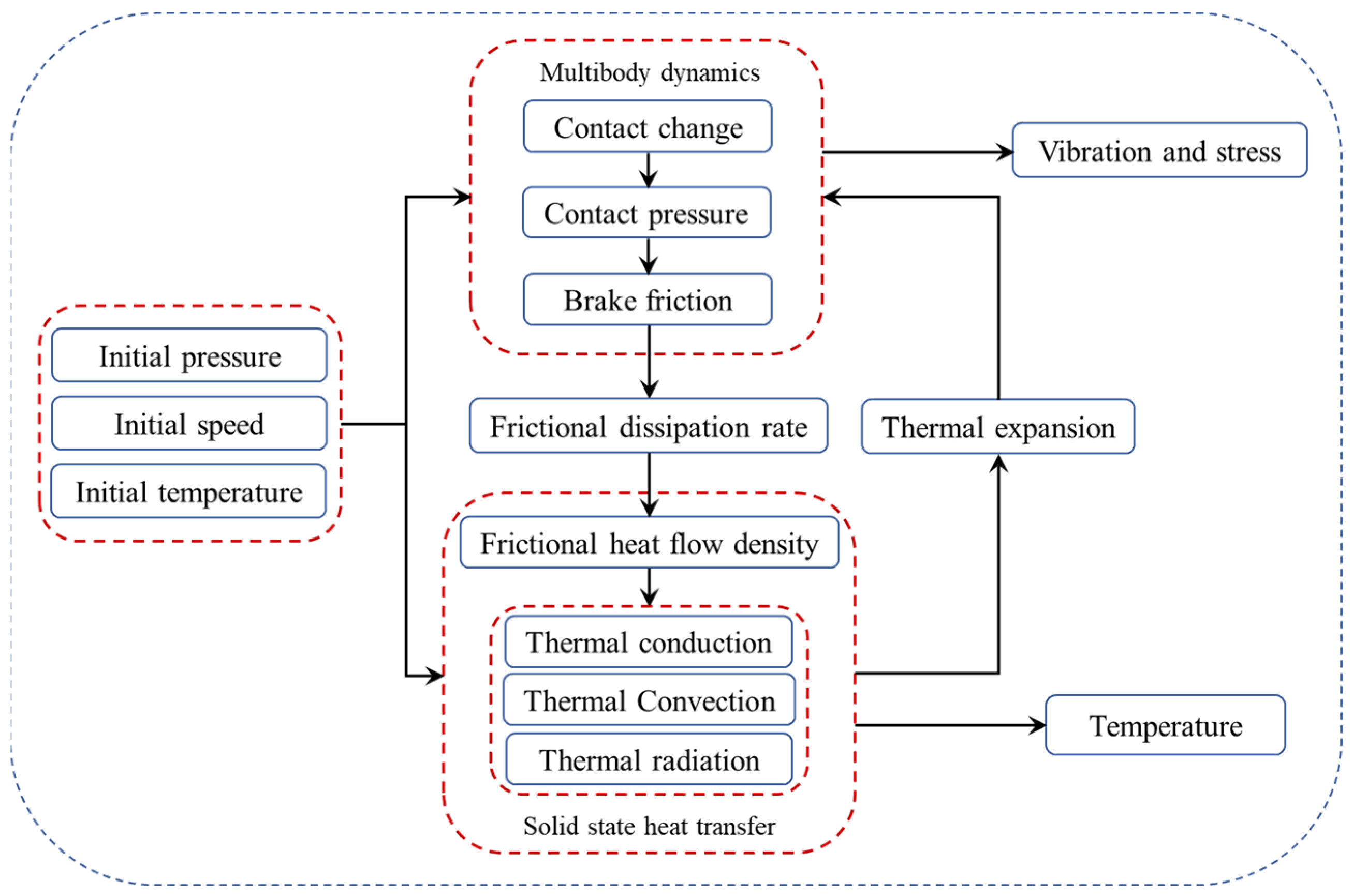
The establishment of the disc brake multi-physical field coupling model takes the initial pressure, initial speed, and initial temperature of the high-speed train as the input conditions, and using multi-body dynamics to analyze its contact changes, the contact pressure and friction force changes between the brake disc surface and the brake pad can be obtained. In addition, the dissipation rate of friction during braking is analyzed from the perspective of energy transfer. Based on the dissipation rate of friction, the frictional heat flux is gained. Additionally, the changing rules of temperature and thermal expansion of the brake disc surface and brake pad are obtained from the perspective of structural heat transfer, heat radiation, heat convection, and heat conduction. Furthermore, the change of the contact between the brake disc surface and the brake pad after the expansion deformation is analyzed, and the characteristics of vibration during the braking process are obtained. The coupling relationship between physical fields in this method is shown in Figure 2.
When the brake is working, the friction work causes the kinetic energy of the brake disc to be lost and converted into heat energy. The dissipation rate of friction is obtained through the calculation of multi-body dynamics. The dissipation rate of friction can be expressed as [22]:
Q b = p b A
where Pb is the braking power of the friction force acting on the brake disc, and A is the contact area between the brake disc surface and the brake pad.
Loading the dissipation rate of friction on the contact surface of the brake disc and the brake pad as a frictional heat source, the generated heat flux can be expressed as [23]:
q = μ p ω r
where q is the heat flux generated at the radius r of the brake disc, μ is the friction coefficient, p is the load on the contact surface of the brake disc, and ω is the rotation speed of the brake disc.
The brake disc surface and brake pads generate significant heat due to friction. When the heat generated by the brake is the same as the output heat, the energy equation can be expressed as:
Q = k A Δ T
where Q is the heat transferred during the coupling process, k is the heat transfer coefficient, ΔT is the average temperature difference during the heat transfer process, and A is the area that transfers heat.
When the temperature of the brake changes, its material responds through a volume change, which can be expressed as the thermal strain of εth, and its calculation formula can be expressed as:
ε t h = α ( T T ref )
where T is the working temperature of the brake; Tref is the volume reference temperature of the brake, that is, the temperature when no thermal expansion occurs; and α is the secant thermal expansion coefficient of the brake material, which can be expressed as:
α = e L L 0 1 T T ref
where L is the length of the material after expansion, and L0 is the reference length of the material.
The thermal expansion of the brake is restricted and cannot occur freely under the constraints of its boundary conditions, so large thermal stress is generated. For linear elastic materials, the relationship between the thermal stress σ and its strain can be expressed as:
σ = D ( ε ε th )
where D is the elasticity matrix of the brake.
The structure of the disc brake will be deformed due to the change in temperature during the braking process. This effect is considered through thermal expansion. At the same time, the structural deformation parameters can be calculated according to the data of the brake temperature field to provide additional displacement for the multi-body dynamic motion solution. It will, in turn, affect the motion solution of multi-body dynamics.

3. Multi-Body Dynamics Analysis Model of Disc Brake Coupling in High-Speed Trains

3.1. Geometric Model of High-Speed Train Disc Brake

The complex brake model was somewhat simplified, and the unnecessary structure was simplified to increase the simulation calculation efficiency and grid quality. All other connection structures were ignored, and only the brake disc and brake pads were reserved. Overall, 72 ventilation channels were evenly distributed along the circumference of the brake disc, and its friction radius was 260 mm. The brake disc and brake pad geometry and geometric model for high-speed trains were finally established. The dimensions are shown in Figure 3.

3.2. Finite Element Model of Disc Brake Braking Process

3.2.1. Assumptions

To facilitate the multi-physical field coupling simulation of disc brakes, corresponding simplifications were performed in the modeling process, and the braking process of disc brakes was simulated as realistically as possible. The following assumptions were made when the finite element model was established:
(1)
The brake disc and brake pads are comprised of isotropic materials.
(2)
The initial temperature of the brake disc, brake pads, and ambient temperature are both 20 °C.
(3)
The phenomenon of friction pair wear and material damage during braking is ignored.

3.2.2. Establishment of Finite Element Model

The geometric model of the high-speed train brake disc/brake pad was meshed using COMSOL 5.6 software. There were many connecting parts between the surfaces of the brake disc and the ventilated blades. Direct meshing can lead to uneven mesh distribution, which can have negative effects on calculation accuracy and convergence. In addition, considering the continuity of the mesh nodes, mesh sectioning was used to divide the two. To obtain uniform grid distribution, the brake pads and brake disc friction surfaces were divided into free tetrahedral meshes, and the ventilated blades of the brake disc were hexahedral meshes. In addition, to guarantee calculation accuracy, the mesh was adaptively divided according to extremely fine specifications. After mesh division, the number of meshes in this model was 75,113, and the number of nodes was 28,536. The material of brake disc was comprised of low-alloy steel, and the material of the brake pad was comprised of copper-based powder metallurgy material. The corresponding material parameters are shown in Table 1.
According to the actual working principle of high-speed train disc brakes, the multi-body dynamics method was used to set motion constraint boundary conditions for high-speed train disc brakes, and the relative motion relationship between the brake disc and the brake pad was transformed. The constraint relationship was added between the components of the brake according to the kinematic pair shown in Table 2. An interference fit was used to assemble the axle and the inner ring of the brake disc. The connecting portion of the inner ring of the brake disc was set as a rigid area to prevent the inner ring part from deforming. The area could act as a constraint for the remaining flexible parts of the brake disc. Using a rotating pair and restricting other degrees of freedom, the brake disc could only rotate around the axis, and the initial speed needed for rotation is set at 200 km/h. The brake pad restricted other degrees of freedom through the translation pair while achieving axial movement during the braking process and provided the required braking pressure of 0.36 MPa during the braking process. In addition, the contact type between the brake disc and the brake pad was defined as friction contact through the contact pair, the penalty function method was used for simulation calculation, and the friction coefficient was set to 0.3. The entire simulation process was divided into two steps. The brake disc speed rose to the predetermined value in the first 0.1 s, and the brake started braking after 0.1 s until the brake disc speed drops to 0.
The heat generated by the brake disc and the brake pad was loaded on the contact surface of the brake disc and the brake pad in the form of the dissipation rate of friction, and it was used as a friction input heat source for structural heat transfer. The heat transfer between the brake disc and the brake pad was realized through the pair thermal contact, the initial temperature of the brake disc and the brake pad and the ambient temperature was set to 20 °C, and the convective heat transfer and thermal radiation were set at the contact boundary between the brake surface and the air. When defining the thermal radiation boundary condition of the brake disc surface, the effect of temperature change on the brake surface emissivity was ignored, that is, it was assumed to be a constant.
The high-speed train brake disc/brake pad finite element model is shown in Figure 4.

3.2.3. Verification of Finite Element Model

To ensure the accuracy of the established multi-body dynamics analysis model of the disc brake coupling effect of high-speed trains, this paper adopts a scaled inertial brake test bench (as shown in Figure 5) to test the above model. The initial braking pressure was 0.36 MPa, and the braking condition with the initial speed of 200 km/h was tested. The straight-line distance between the infrared thermal imager and the brake disc surface was 1.5 m, the test environment temperature was 20 °C, the emissivity was set to 0.85, and the ambient humidity was 31%. The signals of the braking time, friction coefficient, and temperature at the friction radius of the brake disc surface during the braking process were collected through a scaled inertia test bench, and the temperature of the brake disc surface was collected through an infrared thermal imaging camera.
The results under the assumptions of the initial braking speed of 200 km/h, the initial pressure of 0.36 MPa, and the initial temperature of 20 °C were derived through the analysis and calculation of the model constructed in Section 3.2.2. Figure 6 illustrates a comparison between the temperature curve during the braking process obtained from the aforementioned scaled inertial braking test and the temperature curve at the surface friction radius (R = 260 mm) of the high-speed train brake disc.
In Figure 6, the temperature curve obtained from the simulation and the test both exhibit the same overall change trend, which is a parabolic change. The temperature rose quickly during the initial stages of braking due to the high rotation speed of the brake disc, high dissipation rate of friction of the brake pads to the brake disc, and high heat flow intensity. The temperature curve obtained by simulation reached its maximum value of 226 °C at 30 s, while the temperature curve obtained by test reached its maximum value of 235 °C at 34 s. The heat flow intensity decreased, the dissipation rate of friction gradually decreased, and the speed of the brake disc further decreased as the braking process continued. The effects of heat conduction, convective heat transfer, and radiation heat dissipation of the brake disc were greater than those of the frictional heat flow. The test temperature fell to 169 °C until the end of braking, while the simulated temperature dropped to 190 °C. Comparing the two curves, the test temperature rise rate was lower than the simulation before 28 s because of the uneven contact between the brake disc and the brake pad. The temperatures of the two gradually tended to be the same, and after 42.5 s as the braking progresses, the test temperature value was marginally lower than the simulated temperature value. Considering the influence of the test error comprehensively, the simulation temperature change curve of the brake disc and the temperature change curve of the test brake were both parabolic and shared the same temperature change regulations, so the accuracy of the simulation model was confirmed.

4. Analysis Results and Discussion of Coupled Multi-Body Dynamics

4.1. Analysis of Thermo-Solid Coupling Characteristics during Braking

4.1.1. Temperature Change Results of the High-Speed Train Brake Disc

The temperature on the surface of the brake disc changes with the braking time during the braking process of high-speed trains, and its temperature distribution also has certain rules. The temperature field distribution on the surface of the brake disc during the braking process of the high-speed train is shown in Figure 7. Figure 7a–d, are respectively, the temperature contours of the brake disc at the initial braking time t = 0.5 s, t = 10 s, the highest temperature time t = 30 s, and the braking end time t = 56.6 s.
The temperature of the brake disc generally shows a trend of rising initially and then declining as braking progresses because of the continuous frictional heat generation between the brake disc and the brake pad, as well as the effects of convective heat transfer and radiation heat dissipation. The high-temperature area on the disc surface is mainly concentrated in the friction contact area between the brake disc and the brake pad and is distributed in a ring shape. This is mainly due to the rotational compaction effect caused by the friction force, which increases the local contact stress at the friction radius of the brake disc. Therefore, heat accumulates continuously at the friction radius, and the temperature rises, and the highest temperature reached 226 °C in 30 s. As the braking process proceeds, the heat is transferred from the high-temperature area of the braking interface to the surroundings and the interior of the brake disc through the heat conduction of the material. In different regions of the brake disc, the radial temperature distribution is significantly different, and the temperature gradually decreases from the friction radius to both sides, forming a large temperature gradient.

4.1.2. Results of Stress Field Distribution of High-Speed Train Brake Disc

Temperature gradient action causes the brake disc to expand and deform, but due to boundary condition restrictions, the phenomenon cannot happen naturally, causing the brake disc to produce a substantial amount of thermal stress. At the same time, the rotation of the brake disc is driven by the rigid connection between the rotating pair and the inner ring. The creation of a stress concentration during the deceleration causes mechanical stress in this area. Figure 8a–c are the stress contours of the brake disc at the initial braking time t = 0.5 s, t = 10.0 s, the maximum stress time t = 22.8 s, and the braking end time t = 56.6 s, respectively.
Similar to the temperature change, the overall change in brake disc stress presented a rising and then dropping tendency. During the entire working process of the brake, the maximum stress occurred at 22.8 s, which was earlier than the maximum temperature. This was mainly because at this time, compared with the mechanical stress, the thermal stress of the brake disc played a dominant role, and the temperature had a great influence on the thermal stress distribution.
When the temperature rises to a certain value, due to the decrease of the heat flux of the friction pair, it begins to enter a slow rising stage. At this time, the temperature of the disc surface reaches approximately the peak value, while the internal temperature of the disc body is relatively low. The temperature difference between the inside and outside of the brake disc reaches the highest, and there is a large temperature gradient. The disc body expands and deforms when heated, and internal constraints limit its unrestricted growth. Therefore, a large stress is generated, reaching a maximum of 198 MPa. Additionally, the stress on the disc surface is mainly concentrated in the friction radius area of the brake disc and distributed in a ring shape. The main reason is that the vibration of the brake disc and the brake pad causes the friction pair to form repeated contact and clutch states, which affects the stress distribution on the friction disc surface of the brake disc.

4.1.3. Surface Deformation Distribution Results of the High-Speed Train Brake Disc

The thermal deformation of the brake disc is a manifestation of the thermo-solid coupling effect in the process of the brake disc. The brake disc warps to varying degrees during the whole braking process. To further clarify the warping deformation of the brake disc during the braking process, the deformation contours of the brake disc were extracted at the initial braking time t = 0.5 s, the maximum deformation time t = 30 s, and the braking end time t = 56.6 s. The result is shown in Figure 9.
The thermal warpage deformation of the brake disc follows the same general trend as changes in temperature, which is an increase followed by a decrease. The temperature change and the overall trend is to increase first and then decrease. In the brake to 30 s, the brake disc temperature reached the maximum when its warpage deformation also reached the maximum (0.44 mm). This shows that the deformation of the brake disc is affected by its temperature change. The warping deformation area of the brake disc was mainly concentrated close to the friction radius, and the radial deformation distribution was quite different. The deformation at the friction radius of the brake disc was quite greater than the deformation at both sides. The frictional contact surface of the brake disc lost its flatness due to variations in the degree of deformation at different locations. The above changes were mainly due to the circular distribution of the surface temperature of the brake disc friction disc and the large temperature gradient in the radial direction, resulting in large internal thermal stress. Uneven distribution of temperature and stress is the main cause of thermal warpage deformation of the brake disc.
Figure 10 shows the results at the time of maximum deformation, t = 30 s, obtained by extracting the deformation contours of the brake disc’s friction surface and then enlarging its axial scale factor to 500 times. This allows for a more intuitive observation of the thermal deformation distribution of the friction surface of the brake disc.
The temperature rise of the brake disc during the braking process causes it to warp and deform, and the entire friction disc surface loses its flatness during the braking process. As shown in Figure 10, the overall axial deformation of the brake disc surface was in the same direction. The frictional contact area had different degrees of warping deformation under the influence of uneven temperature distribution. The phenomenon of “annular protrusion” appeared, and the entire friction surface was distributed in a drum shape. Changes in temperature cause deformation of the brake disc and affect its contact area. In the case of heating, the occurrence of thermal warping deformation of the brake disc will cause the action point of the contact pressure of the friction pair to move. The brake disc and brake pad cannot form good contact with each other, the contact state of the friction pair changes. There is a local contact behavior between the two, and their effective contact area is constantly changing and much smaller than the nominal contact area. Therefore, the middle part of the brake disc will be continuously squeezed and impacted by the brake pads during the braking process, causing an uneven distribution of contact pressure between the braking interfaces, which results in vibration during the braking process.

4.2. Influence of Thermo-Solid Coupling on the Vibration Characteristics of Brake Disc

The friction contact state of disc brakes is directly impacted by the uneven distribution of temperature and stress, which causes varying degrees of warpage and deformation at different locations. This leads to incomplete contact between the brake disc and brake pad during braking, which causes brake vibration. To further analyze the effect of thermoset coupling on the vibration characteristics of the disc braking system, this paper compares the vibration acceleration signals of the brake model with/without thermoset coupling. Figure 11 shows the axial vibration acceleration of the brake discs obtained from the two different models, and the trends of both were approximately the same.
The brake disc vibrated continuously when the brake model did not consider the thermo-solid coupling effect. In contrast, the axial vibration acceleration range was reduced from 601 m/s2 to 497 m/s2 when the model considered the thermos-solid coupling effect. The variation of the axial vibration amplitude of the brake disc was significantly less than that without considering the frictional heat effect.
The above results show that the thermo-solid coupling effect had a great influence on the vibration characteristics of the brake disc. This was mainly because, when the thermo-solid coupling was not considered, the work done by the frictional force impeding the movement of the brake disc mainly converted the energy of the disc into the unstable vibration of the brake. However, when the thermo-solid coupling was considered in the model, the work done by the frictional force was not only converted into the unstable vibration of the brake but also converted into heat energy and continuously exchanges heat with the air. The energy released by the brake disc through vibration was reduced. As a result, the axial vibration intensity of the brake disc was reduced. In summary, when researching and analyzing the vibration characteristics of disc brakes, it is necessary to consider the influence of thermo-solid coupling, so as to accurately reflect the vibration characteristics of the brake.

4.3. Influence of Braking Parameters on the Vibration Characteristics of the Brake Disc

4.3.1. Influence of Brake Pressure Changes on the Vibration Characteristics of the Brake Disc

To study the influence of brake pressure changes on the vibration characteristics of the brake disc, under the premise that the initial braking speed remains constant at 200 km/h, multi-physical field coupling simulations were run on the brake finite element model at brake pressures of 0.23 MPa, 0.36 MPa, and 0.49 MPa, respectively. After the overall axial vibration displacement range and root mean square value of vibration velocity were extracted, the change results of the brake disc vibration characteristics under the change of brake pressure were obtained, as shown in Figure 12.
Figure 12a–c are, respectively, the brake disc vibration displacement-time curve, axial vibration displacement range-brake pressure bar graph, and axial vibration velocity RMS value-brake pressure graph. Figure 12a illustrates that the variation range of the axial vibration displacement amplitude of the brake disc gradually increased with the increase of the brake pressure. Figure 12b shows that when the brake pressure was 0.23 MPa, 0.36 MPa, and 0.49 MPa, the difference between the maximum value and the minimum value of the axial vibration displacement of the brake disc was 3.8 × 10⁻⁵ m, 5.04 × 10⁻⁵ m, and 8.82 × 10⁻⁵ m, respectively. Its value exhibited an increasing trend as the brake pressure was increased. It can be seen from Figure 12c that the axial vibration intensity, that is, the effective value of the axial vibration velocity, increased gradually with the increase of the brake pressure. From Figure 12a–c, it can be concluded that when the brake pressure increased, the brake disc axial vibration amplitude increased at the same time, and vibration speed was faster, that is, the brake disc axial vibration intensity was increasing. The main reasons leading to the above phenomenon are as follows: When the brake pressure on the brake pad increases, the friction force on the brake disc also increases, and the mechanical friction between the brake disc and the brake pad raises the friction pairs product heat. The increase in the temperature of the brake disc leads to greater thermal stress and thermal deformation. The reduction of the contact area of the friction pair affects its contact state. The brake disc and the brake pad cannot form a good and effective contact, causing a phenomenon of contact separation, which leads to aggravated vibration. At the same time, to overcome the effect of the increased frictional force on its movement, the brake disc resists this increasingly strong obstruction. In addition, the increase in the brake pressure will have a stronger impact on the brake disc, resulting in a more unstable vibration characteristic and aggravated axial vibration.

4.3.2. Influence of the Change of Braking Speed on the Vibration Characteristics of the Brake Disc

To further study the influence of the change of braking speed on the vibration characteristics of the brake disc, the finite element model of the brake was subjected to multi-physics coupling simulation at the initial braking speeds of 150 km/h, 200 km/h, and 250 km/h, respectively. After extracting the overall axial vibration displacement range and root mean square value of vibration velocity, the change results of the vibration characteristics of the brake disc under the change of the initial braking speed are shown in Figure 13.
Figure 13a–c are, respectively, the brake disc vibration displacement-time curve, the axial vibration displacement range-braking speed bar graph, and the root mean square value of the axial vibration velocity graph. It can be seen from Figure 13a that the variation range of the axial vibration displacement of the brake disc increased with the increase of the braking speed; It can be seen from Figure 13b that when the braking initial velocity was 150 km/h, 200 km/h, and 250 km/h, the ranges of axial vibration displacement of the brake disc were 4.32 × 10⁻⁵ m, 5.04 × 10⁻⁵ m, and 7.89 × 10⁻⁵ m, respectively, and the value increased with the increase of the braking initial velocity. It can be seen from Figure 13c that the axial vibration intensity of the brake disc increased gradually with the increase of the initial braking speed. From Figure 13a–c, it can be concluded that when the initial braking speed increased, the axial vibration amplitude of the brake disc increases and the vibration speed became faster, that is, the intensity of the axial vibration of the brake disc was intensified. The main reasons leading to the above phenomenon are as follows: When the braking speed increases, the friction contact scratching distance between the brake disc and the brake pad per unit time increases, and the work done by the friction force between the friction pairs increases. The effect of frictional work is to convert the mechanical energy of the brake disc and release it in the form of heat and vibration. Therefore, when the braking speed increases, the energy released by the brake disc through vibration increases, which leads to the intensification of its axial vibration. At the same time, the heat generated by the friction pair increases due to the work done by friction, and the heat is transferred to the brake disc through the heat conduction of the material to increase the temperature and cause greater thermal warpage.

5. Conclusions

This paper establishes a multi-body dynamics model of high-speed train disc brake thermo-solid coupling, obtains the disc surface temperature through a scaled inertia braking experiment, and compares it with the model temperature to verify the accuracy of the model. The changing rules of temperature, stress, and strain of the brake disc under the influence of vibration are obtained through the mode. Comparing the results with and without considering the thermal coupling effect, the influence of the thermo-solid coupling effect of the brake on its vibration characteristics is discussed. In addition, by extracting the vibration displacement range and root mean square value of vibration velocity at different rotating speeds and pressures, the change regulation of the vibration characteristics of the brake disc under the change of the braking speed and braking pressure is analyzed. However, due to the complexity of multi-physical field coupling analysis and the difficulty in convergence of calculations, this study does not consider the impact of wind load on vibration in the flow field during the braking process, and the impact of friction and wear on vibration during braking is not discussed. Therefore, subsequent research can be carried out from these perspectives.
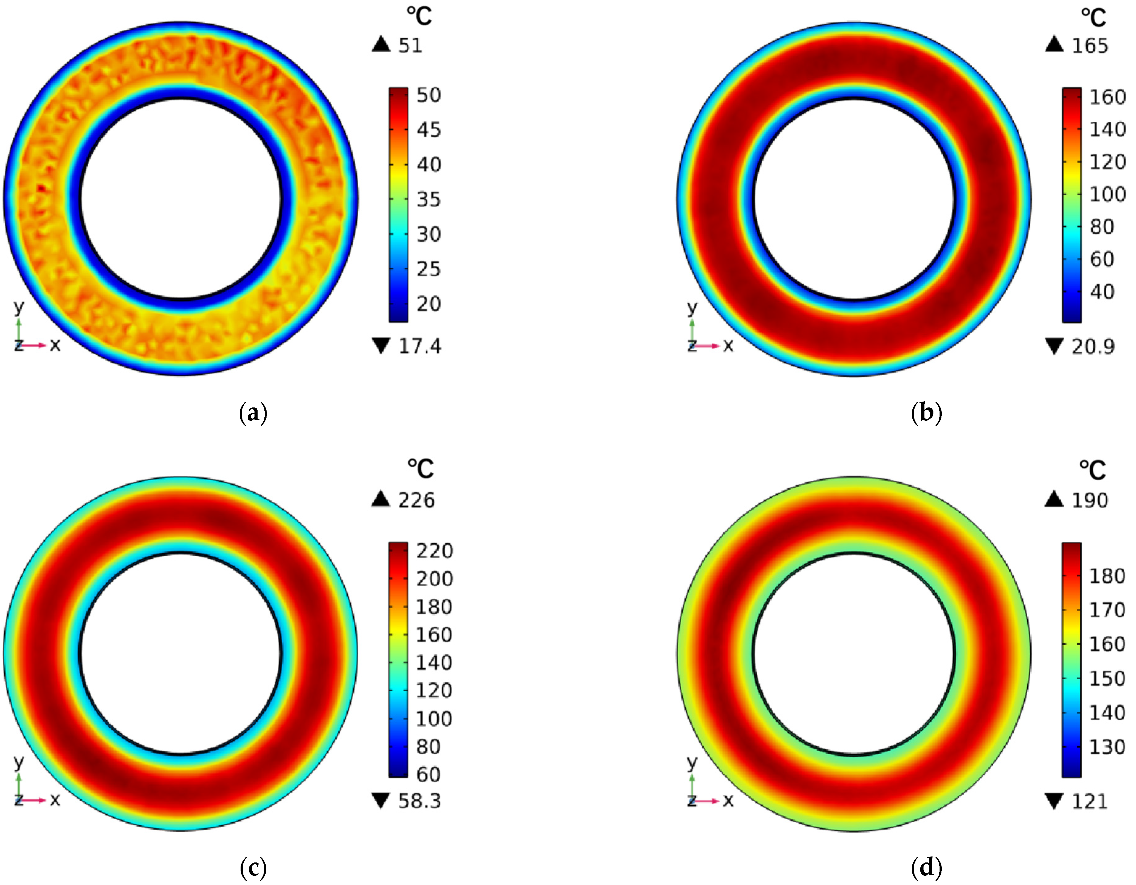
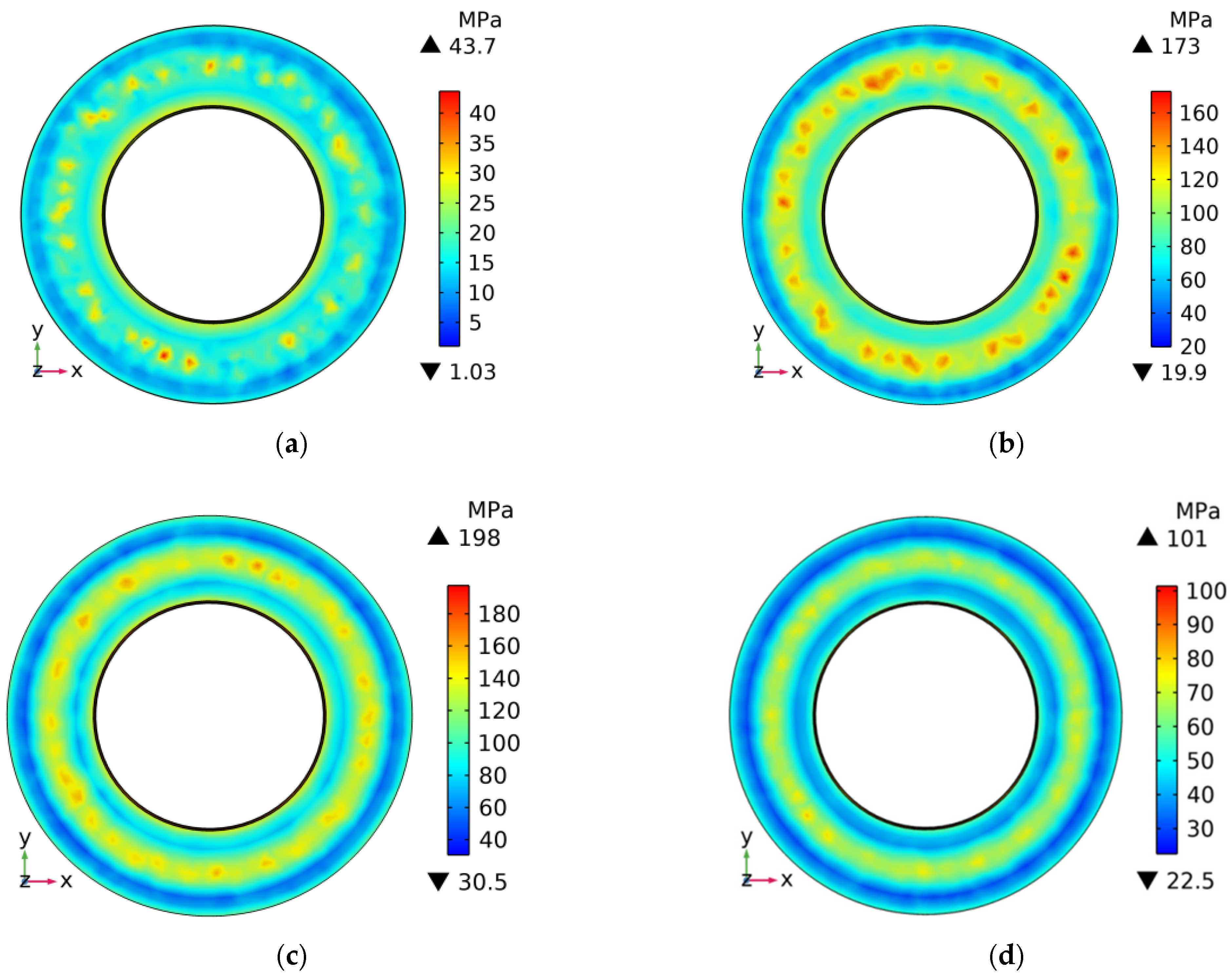
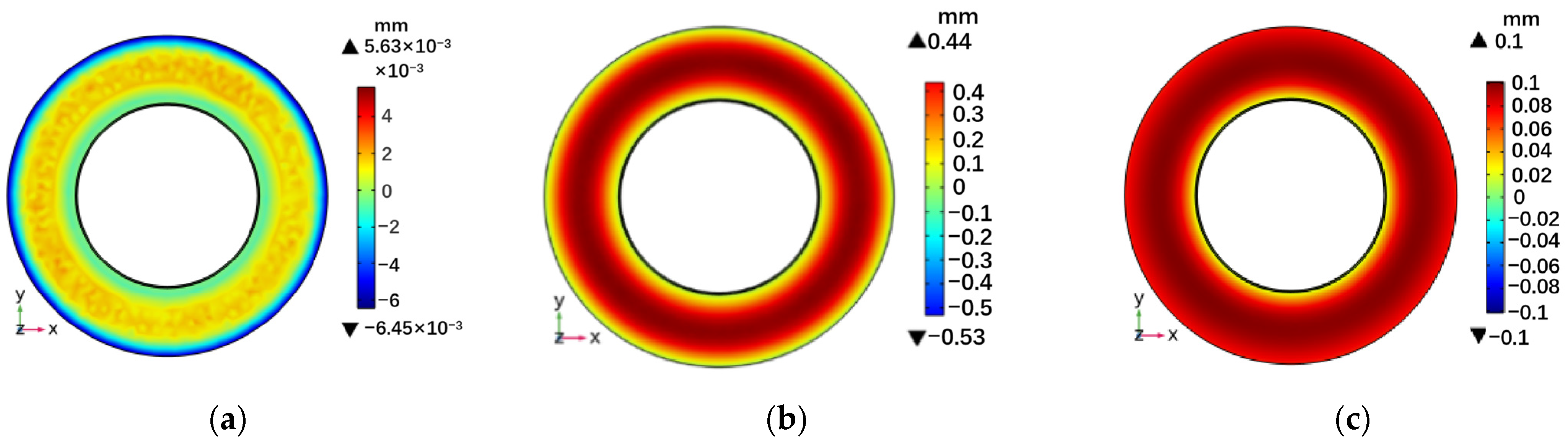
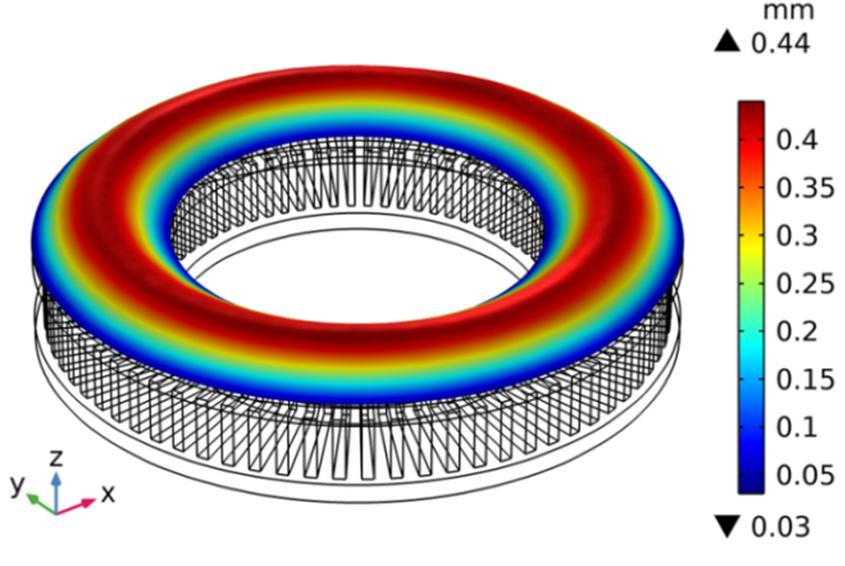
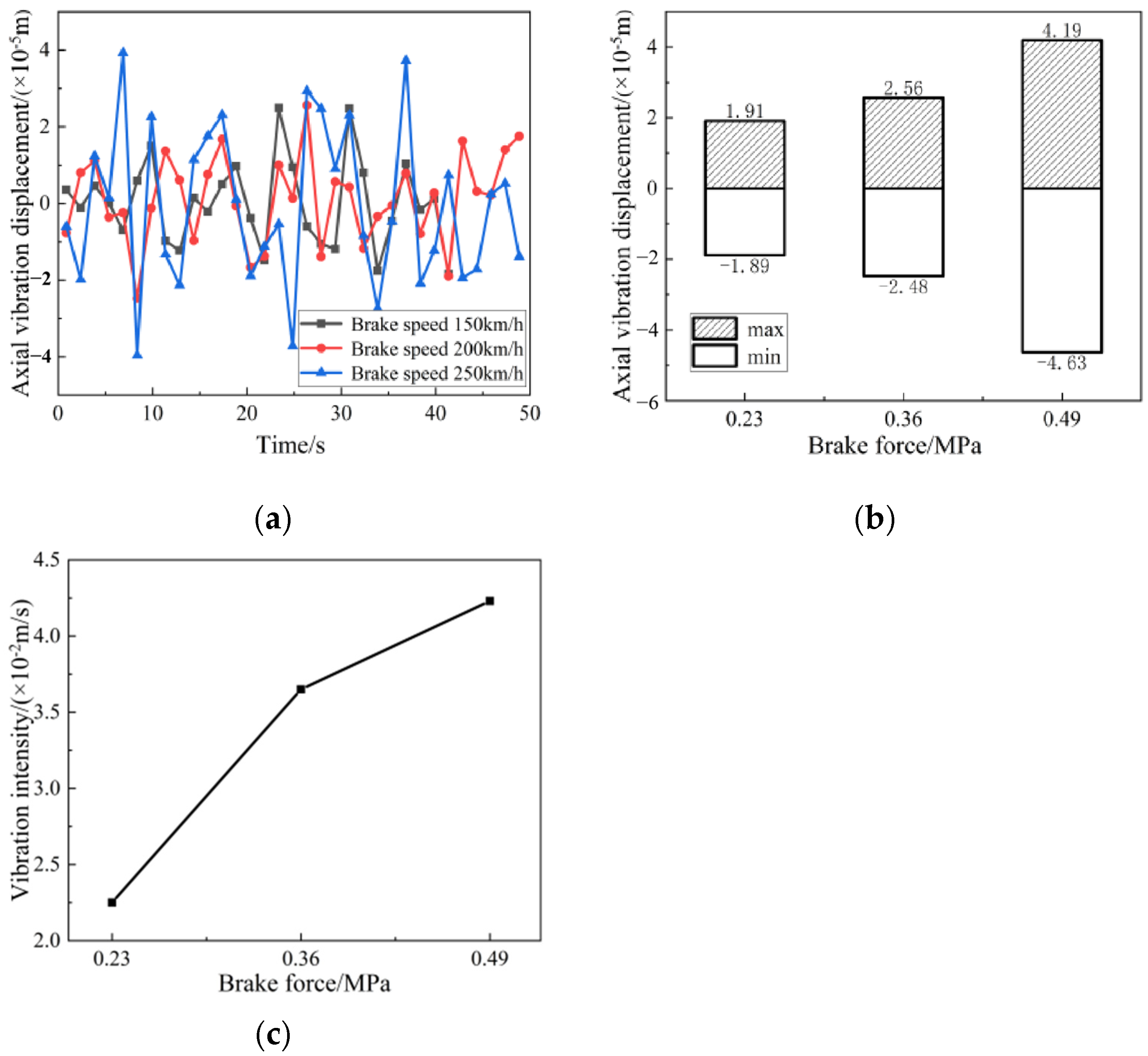
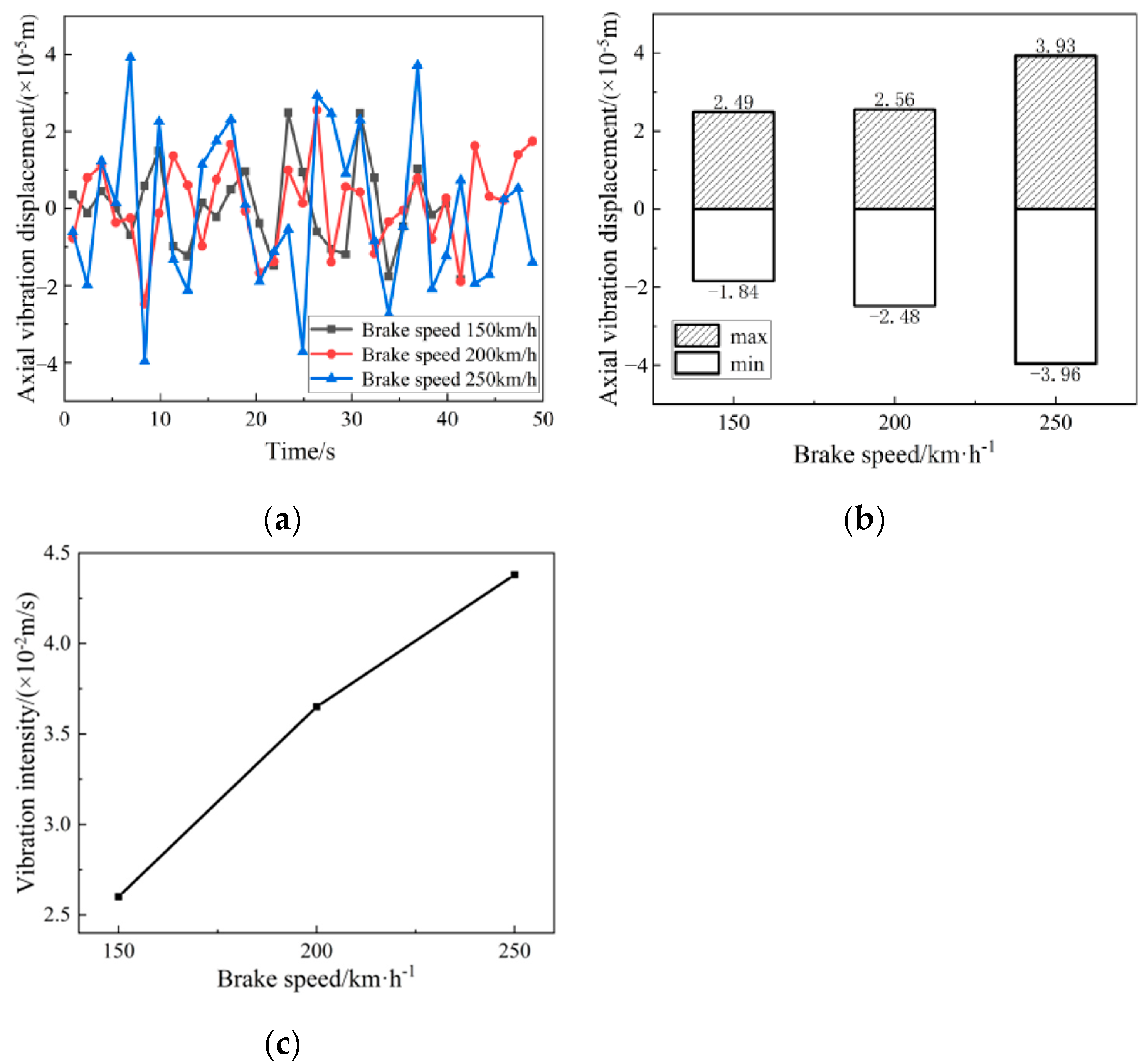
Key findings include the establishment of a multi-body dynamics analysis model for the thermo-solid coupling of high-speed train disc brakes, which effectively analyzed vibration characteristics considering thermo-solid coupling effects. During the braking process, the surface temperature and stress of the brake disc were in a dynamic change process, and there was stress concentration and obvious high-temperature concentration in the friction area. When the braking initial velocity was 200 km/h and the braking pressure was 0.36 MPa, the maximum temperature and stress of the brake disc reached 226 °C and 198 MPa, respectively. The temperature and stress concentration will aggravate the local warping deformation of the friction interface. The brake disc underwent different degrees of elastic warping deformation during the braking process, and its maximum deformation reached 0.44 mm. The warping deformation caused the frictional contact surface of the brake disc to lose its flatness, resulting in uneven contact between the brake disc and the brake pad. This affected their contact state and led to the occurrence of brake vibration. Furthermore, the thermo-solid coupling effect during the braking process significantly influenced the vibration characteristics of the disc brake. When the model considered the thermo-solid coupling effect, part of the brake disc’s energy was released into the air in the form of heat energy, which reduced the severity of the vibration of the brake disc. With the increase of the initial braking speed and braking pressure, the axial vibration displacement of the brake disc increased, and the vibration velocity increased at the same time, that is, the axial vibration of the brake disc intensified.

Author Contributions

J.Y. and Q.Z.: conceptualization, methodology; Q.Z. and J.Y. conducted the simulation; data curation; Q.Z.: original draft preparation, X.F.: review and editing, Z.S. and Y.L.: supervision, funding acquisition; Z.L. and S.Z.: project administration. All authors have read and agreed to the published version of the manuscript.

Funding

This research was funded by National Natural Science Foundation of China (52375169), Liaoning Provincial Science and Technology Program (No. 2022JH2/101300228), Liaoning Provincial Doctoral Research Foundation Project (No. 2022-BS-260), Liaoning Provincial Department of Education Scientific Research Project (LJKZ0479) and Liaoning Provincial Department of Transport Research Project (No. 202148).

Institutional Review Board Statement

Not applicable.

Informed Consent Statement

Not applicable.

Data Availability Statement

The data used to support the findings of this study are available from the corresponding author upon request. The data are not publicly available due to privacy.

Acknowledgments

Thanks to Zhiyi Leng and Haoyang Ma for their writing guidance and to Jiacheng Lu for his theoretical guidance.

Conflicts of Interest

The authors declare that there is no conflict of interest regarding the publication of this paper.

References

  1. Yevtushenko, A.; Kuciej, M.; Grzes, P.; Wasilewski, P. Comparative analysis of temperature fields in railway solid and ventilated brake discs. Materials 2021, 14, 7804. [Google Scholar] [CrossRef]
  2. Popescu, F.D.; Radu, S.M.; Andraș, A.; Brînaș, I.; Budilică, D.I.; Popescu, V. Comparative analysis of mine shaft hoisting systems’ brake temperature using finite element analysis (FEA). Materials 2022, 15, 3363. [Google Scholar] [CrossRef] [PubMed]
  3. Mithlesh, S.; Tantray, Z.A.; Bansal, M.; Kotte, V.; Kumar, K.P.; Kurakula, V.S. Improvement in performance of vented disc brake by geometrical modification of rotor. Mater. Today Proc. 2021, 47, 6054–6059. [Google Scholar] [CrossRef]
  4. Saffari, P.R.; Thongchom, C.; Jearsiripongkul, T.; Saffari, P.R.; Keawsawasvong, S.; Kongwat, S. Thermo-vibro-acoustic analysis of pavement under a harmonically rectangular moving load. Int. J. Thermofluids 2023, 20, 100409. [Google Scholar] [CrossRef]
  5. Dubale, H.; Paramasivam, V.; Gardie, E.; Chekol, E.T.; Selvaraj, S.K. Numerical investigation of thermo-mechanical properties for disc brake using light commercial vehicle. Mater. Today Proc. 2021, 46, 7548–7555. [Google Scholar] [CrossRef]
  6. Jiregna, I.T.; Lemu, H.G. Thermal stress analysis of disc brake using analytical and numerical methods. In Proceedings of the IOP Conference Series: Materials Science and Engineering, Moscow, Russia, 25–26 November 2021. [Google Scholar]
  7. Park, J.P.; Choi, Y.S. Brake squeal noise due to disc run-out. Proc. Inst. Mech. Eng. Part D J. Automob. Eng. 2007, 221, 811–821. [Google Scholar] [CrossRef]
  8. Lyu, H.; Walsh, S.J.; Chen, G.; Zhang, L.; Qian, K.; Wang, L. Analysis of friction-induced vibration leading to brake squeal using a three degree-of-freedom model. Tribol. Lett. 2017, 65, 105. [Google Scholar] [CrossRef]
  9. Lazzari, A.; Tonazzi, D.; Massi, F. Squeal propensity characterization of braking lining materials through friction noise measurements. Mech. Syst. Signal Process. 2019, 128, 2112–2118. [Google Scholar] [CrossRef]
  10. Zhang, L.; Dong, Y.; Meng, D.; Li, W. A Hybrid Model for Predicting Steering Brake Squeal Based on Multibody Dynamics and Finite Element Methods. Shock Vib. 2022, 19, 498. [Google Scholar] [CrossRef]
  11. Gao, P.; Du, Y.; Walker, P.D. Vibration energy and repeated-root modes of disc rotor for high-frequency brake squeal. Proc. Inst. Mech. Eng. Part K J. Multi-Body Dyn. 2019, 233, 363–378. [Google Scholar] [CrossRef]
  12. Chen, F.; Ouyang, H.; Wang, X. A new mechanism for friction-induced vibration and noise. Friction 2023, 11, 302–315. [Google Scholar] [CrossRef]
  13. Zhu, Q.; Xie, J.; Zhang, W.; Chen, G.; Tuo, J. Effect of the braking pressure on disc brake squeal of a railway vehicle. Wear 2023, 522, 204884. [Google Scholar] [CrossRef]
  14. Ghorbel, A.; Zghal, B.; Abdennadher, M.; Walha, L.; Haddar, M. Investigation of friction-induced vibration in a disk brake model, including mode-coupling and gyroscopic mechanisms. Proc. Inst. Mech. Eng. Part D J. Automob. Eng. 2020, 234, 887–896. [Google Scholar] [CrossRef]
  15. Wang, D.; Wang, R.; Heng, T.; Xie, G.; Zhang, D. Tribo-Brake characteristics between the brake disc and brake shoe during emergency braking of deep coal mine hoist with the high speed and heavy load. Energies 2020, 13, 5094. [Google Scholar] [CrossRef]
  16. Balaji, V.; Lenin, N.; Anand, P.; Rajesh, D.; Bupesh Raja, V.K.; Palanikumar, K. Brake squeal analysis of disc brake. Mater. Today Proc. 2021, 46, 3824–3827. [Google Scholar] [CrossRef]
  17. Xiang, Z.Y.; Mo, J.L.; Ouyang, H.; Massi, F.; Tang, B.; Zhou, Z.R. Contact behavior and vibrational response of a high-speed train brake friction block. Tribol. Int. 2020, 152, 106540. [Google Scholar] [CrossRef]
  18. Cascetta, F.; Caputo, F.; De Luca, A. Squeal frequency of a railway disc brake evaluation by FE analyses. Adv. Acoust. Vib. 2018, 2018, 1687–6261. [Google Scholar] [CrossRef]
  19. Yan, X.; Fan, C.; Wang, W.; Liu, X.; Chen, B. Study on the influence of radial stiffness on the nonlinear vibration of brake system. Ind. Lubr. Tribol. 2022, 74, 10–17. [Google Scholar] [CrossRef]
  20. Wang, Z.W.; Zhang, L.; Ren, Z.Y.; Mo, J.L.; Yang, L.C.; Wang, K.Y. Friction and vibration behaviours of high-speed train brake system excited by wheel flats. Int. J. Rail Transp. 2023, 1–18. [Google Scholar] [CrossRef]
  21. Zhang, H.; Qiao, J.; Zhang, X. Nonlinear dynamics analysis of disc brake frictional vibration. Appl. Sci. 2022, 12, 12104. [Google Scholar] [CrossRef]
  22. Ilie, F.; Cristescu, A.C. Tribological behavior of friction materials of a disk-brake pad braking system affected by structural changes—A review. Materials 2022, 15, 4745. [Google Scholar] [CrossRef] [PubMed]
  23. Hua, Y.C.; Zhao, T.; Guo, Z.Y. Optimization of the one-dimensional transient heat conduction problems using extended entrance analyses. Int. J. Heat Mass Transf. 2018, 116, 166–172. [Google Scholar] [CrossRef]
Figure 1. High-speed train disc brake: (a) disc brakes installed on high-speed trains, (b) non-uniform temperature distribution on the friction surface during braking.
Applsci 13 12361 g001
Figure 2. Coupling relationship of disc brake multi-body dynamics analysis method under thermo-solid coupling.
Applsci 13 12361 g002
Figure 3. Geometric model of high-speed train brake disc/brake pad.
Applsci 13 12361 g003
Figure 4. Multi-body dynamics analysis model of the disc brake coupling effect of a high-speed train.
Applsci 13 12361 g004
Figure 5. Scaled inertia brake test bench.
Applsci 13 12361 g005
Figure 6. Comparison of the model calculation and the braking test temperature curve.
Applsci 13 12361 g006
Figure 7. Temperature field distribution of brake disc at different braking moments. (a) t = 0.05 s; (b) t = 10 s; (c) t = 30.0 s; (d) t = 56.6 s.
Applsci 13 12361 g007
Figure 8. The stress field distribution of the brake disc at different braking moments: (a) t = 0.5 s; (b) t = 10 s; (c) t = 22.8 s; (d) t = 56.6 s.
Applsci 13 12361 g008
Figure 9. Deformation distribution of brake disc surface at different braking moments: (a) t = 0.5 s; (b) t = 30.0 s; (c) t = 56.6 s.
Applsci 13 12361 g009
Figure 10. Deformation distribution of the brake disc friction surface.
Applsci 13 12361 g010
Figure 11. Axial vibration acceleration of brake disc: (a) thermo-solid coupling was not considered; (b) considering the thermo-solid coupling effect.
Applsci 13 12361 g011
Figure 12. Vibration characteristics of brake disc under changing brake pressure: (a) vibration displacement; (b) extreme difference in vibration displacement; (c) vibration intensity.
Applsci 13 12361 g012
Figure 13. Vibration characteristics of brake disc under changing braking speed: (a) vibration displacement; (b) extreme difference in vibration displacement; (c) vibration intensity.
Applsci 13 12361 g013
Table 1. Material parameters of the brake disc and brake pad.
Material ParametersBrake DiscBrake Pads
Material NameLow-alloy steelCopper-based powder metallurgy
Density/(kg/m3)78505250
Elastic Modulus/(GPa)210180
Poisson’s ratio0.310.3
specific heat capacity/(J/kg·°C)462550
Thermal conductivity/(W/m·°C)4830
Coefficient of expansion/(1/°C)1.28 × 10−51.5 × 10−6
surface emissivity0.280.8
Table 2. Constraint relationship among components of the high-speed train disc brake.
Motor SubtypeComponent 1Component 2
Rotary jointBrake discFixed
Mobile viceBrake padsFixed
Contact pairBrake padsBrake disc
Disclaimer/Publisher’s Note: The statements, opinions and data contained in all publications are solely those of the individual author(s) and contributor(s) and not of MDPI and/or the editor(s). MDPI and/or the editor(s) disclaim responsibility for any injury to people or property resulting from any ideas, methods, instructions or products referred to in the content.

